WO2016162902A1 - 車線維持支援装置 - Google Patents
車線維持支援装置 Download PDFInfo
- Publication number
- WO2016162902A1 WO2016162902A1 PCT/JP2015/002014 JP2015002014W WO2016162902A1 WO 2016162902 A1 WO2016162902 A1 WO 2016162902A1 JP 2015002014 W JP2015002014 W JP 2015002014W WO 2016162902 A1 WO2016162902 A1 WO 2016162902A1
- Authority
- WO
- WIPO (PCT)
- Prior art keywords
- reaction force
- steering
- vehicle
- vehicle speed
- command value
- Prior art date
- Legal status (The legal status is an assumption and is not a legal conclusion. Google has not performed a legal analysis and makes no representation as to the accuracy of the status listed.)
- Ceased
Links
Images







Classifications
-
- B—PERFORMING OPERATIONS; TRANSPORTING
- B62—LAND VEHICLES FOR TRAVELLING OTHERWISE THAN ON RAILS
- B62D—MOTOR VEHICLES; TRAILERS
- B62D15/00—Steering not otherwise provided for
- B62D15/02—Steering position indicators ; Steering position determination; Steering aids
- B62D15/025—Active steering aids, e.g. helping the driver by actively influencing the steering system after environment evaluation
-
- B—PERFORMING OPERATIONS; TRANSPORTING
- B62—LAND VEHICLES FOR TRAVELLING OTHERWISE THAN ON RAILS
- B62D—MOTOR VEHICLES; TRAILERS
- B62D6/00—Arrangements for automatically controlling steering depending on driving conditions sensed and responded to, e.g. control circuits
- B62D6/002—Arrangements for automatically controlling steering depending on driving conditions sensed and responded to, e.g. control circuits computing target steering angles for front or rear wheels
-
- B—PERFORMING OPERATIONS; TRANSPORTING
- B62—LAND VEHICLES FOR TRAVELLING OTHERWISE THAN ON RAILS
- B62D—MOTOR VEHICLES; TRAILERS
- B62D6/00—Arrangements for automatically controlling steering depending on driving conditions sensed and responded to, e.g. control circuits
- B62D6/008—Control of feed-back to the steering input member, e.g. simulating road feel in steer-by-wire applications
-
- G—PHYSICS
- G01—MEASURING; TESTING
- G01P—MEASURING LINEAR OR ANGULAR SPEED, ACCELERATION, DECELERATION, OR SHOCK; INDICATING PRESENCE, ABSENCE, OR DIRECTION, OF MOVEMENT
- G01P3/00—Measuring linear or angular speed; Measuring differences of linear or angular speeds
- G01P3/64—Devices characterised by the determination of the time taken to traverse a fixed distance
-
- B—PERFORMING OPERATIONS; TRANSPORTING
- B60—VEHICLES IN GENERAL
- B60W—CONJOINT CONTROL OF VEHICLE SUB-UNITS OF DIFFERENT TYPE OR DIFFERENT FUNCTION; CONTROL SYSTEMS SPECIALLY ADAPTED FOR HYBRID VEHICLES; ROAD VEHICLE DRIVE CONTROL SYSTEMS FOR PURPOSES NOT RELATED TO THE CONTROL OF A PARTICULAR SUB-UNIT
- B60W2510/00—Input parameters relating to a particular sub-units
- B60W2510/20—Steering systems
- B60W2510/205—Steering speed
Definitions
- the present invention relates to a lane keeping support device that performs lane keeping control of a vehicle.
- Patent Document 1 As a vehicle lane keeping support device, for example, there is a technique described in Patent Document 1.
- a technique described in Patent Document 1 in a vehicle in which a steering wheel provided in the vehicle and a steered wheel that steers the vehicle are mechanically separated, an offset amount according to a yaw angle that is an angle formed by the white line and the traveling direction of the host vehicle.
- the steering reaction force characteristic is offset to reduce the steering burden when the driver performs corrective steering in order to return the vehicle approaching the end of the lane to the lane center side.
- An object of the present invention is to provide a lane keeping assist device capable of obtaining an appropriate steering reaction force that reduces a driver's uncomfortable feeling as compared with existing technologies when lane keeping control is performed in a low speed range.
- a lane keeping assist device is a vehicle in which a steering wheel provided in the vehicle and a steered wheel that steers the vehicle are mechanically separated from each other.
- a lane keeping assist device that assists in traveling in a lane, the second turning corresponding to the first turning angle calculated so that the vehicle travels in the traveling lane and the steering amount of the steering wheel.
- the turning angle of the steered wheels is controlled using the angle, the vehicle speed of the vehicle is detected, the first reaction force command value to the steering wheel corresponding to the first turning angle is calculated, and the second A second reaction force command value for the steering wheel corresponding to the turning angle is calculated, and when the vehicle speed is higher than a predetermined threshold, the steering reaction force corresponding to only the second reaction force command value is applied to the steering wheel.
- To control the steering reaction force When the vehicle speed is less than a predetermined threshold value at a steering reaction force corresponding to the first reaction force command value and the second reaction force command value, and controls the steering reaction force applied to the
- the steering reaction force is calculated based on the steering amount of the steering wheel by the driver without reflecting the result of the lane keeping control in the steering reaction force in the high speed range.
- the lane keeping control is implemented in the low speed range by controlling the steering reaction force using the steering angle by the driver and the steering angle according to the lane keeping control in the low speed range
- FIG. 1 is a block diagram illustrating a configuration example of a steering system of a vehicle A equipped with a lane keeping assist device according to the present embodiment.
- the vehicle A includes a steering unit 1, a steering unit 2, a backup clutch 3, and an SBW controller 4.
- the vehicle A employs a steer-by-wire (SBW) system in which a steering unit 1 that receives a driver's steering input and a steering unit 2 that steers left and right front wheels 5FL and 5FR that are steered wheels are mechanically separated.
- the steering unit 1 includes a steering wheel 1a, a column shaft 1b, a reaction force motor 1c, a steering angle sensor 1d, and a torque sensor 1e.
- the steering wheel 1a rotates in response to a driver's steering input.
- the column shaft 1b rotates integrally with the steering wheel 1a.
- the reaction motor 1c has an output shaft that is coaxial with the column shaft 1b, and is applied to the steering wheel 1a in response to a command from the SBW controller 4 (command current output from a reaction force motor current driver 9a described later).
- the reaction torque is output to the column shaft 1b.
- the reaction force motor 1c is a brushless motor or the like.
- the steering angle sensor 1d detects the rotation angle of the column shaft 1b, that is, the steering angle (handle angle) of the steering wheel 1a. Then, the steering angle sensor 1d outputs the detection result to the SBW controller 4 described later.
- the steered portion 2 includes a pinion shaft 2a, a steering gear 2b, a steered motor 2c, a steered angle sensor 2d, a rack 2f, and a rack gear 2e.
- the steering gear 2b steers the left and right front wheels 5FL and 5FR according to the rotation of the pinion shaft 2a.
- a rack and pinion type steering gear or the like can be adopted.
- the steering motor 2c has an output shaft connected to the rack gear 2e via a speed reducer, and the left and right sides of the steering motor 2c are connected to the rack 2f in accordance with a command from the SBW controller 4 (a command current output from a steering motor current driver 9b described later).
- a turning torque for turning the front wheels 5FL and 5FR is output.
- the steered motor 2c is a brushless motor or the like.
- the turning angle sensor 2d detects the rotation angle of the turning motor 2c.
- the turning angles of the left and right front wheels 5FL, 5FR can be detected from the rotation angle of the turning motor 2c.
- the turning angles of the left and right front wheels 5FL and 5FR are calculated from the rotation angle of the turning motor 2c unless otherwise specified.
- the backup clutch 3 is provided between the column shaft 1b and the pinion shaft 2a.
- the backup clutch 3 mechanically disconnects the steering unit 1 and the steered unit 2 when in the released state, and mechanically connects the steered unit 1 and the steered unit 2 when in the engaged state.
- the vehicle A includes a camera 6, various sensors 7, a navigation system 8, and a current driver 9.
- the camera 6 detects an image of a traveling road ahead of the vehicle A. Subsequently, the camera 6 outputs the detection result to the SBW controller 4.
- the various sensors 7 include a vehicle speed sensor 7a, an acceleration sensor 7b, and a yaw rate sensor 7c.
- the vehicle speed sensor 7a detects the vehicle speed of the vehicle A. Subsequently, the vehicle speed sensor 7 a outputs the detection result to the SBW controller 4.
- the acceleration sensor 7b detects the longitudinal acceleration (vertical acceleration) of the vehicle A and the lateral acceleration (lateral acceleration) of the vehicle A. Then, the acceleration sensor 7b outputs the detection result to the SBW controller 4.
- the yaw rate sensor 7c detects the yaw rate of the vehicle A (the state quantity of the vehicle A that varies with the tire lateral force acting on the left and right front wheels 5FL, 5FR). Then, the yaw rate sensor 7 c outputs the detection result to the SBW controller 4.
- the navigation system 8 includes a GPS (Global Positioning System) receiver, a map database, and a display monitor. And the navigation system 8 acquires the position and road information of the vehicle A from a GPS receiver and a map database. Subsequently, the navigation system 8 performs a route search based on the acquired position of the vehicle A and road information. Subsequently, the navigation system 8 displays the route search result on the display monitor. Further, the navigation system 8 outputs the road information of the traveling path of the vehicle A among the acquired road information to the SBW controller 4.
- the road information of the travel path includes the type of travel path (highway, general road), the lane width (lane width information) of the travel path at the current vehicle position, and the like.
- the current driver 9 includes a reaction force motor current driver 9a and a steering motor current driver 9b.
- the reaction force motor current driver 9a applies the actual steering reaction force torque estimated from the current value of the reaction force motor 1c with the command steering reaction force torque from the SBW controller 4 to the reaction force motor 1c. Controls the command current.
- the steered motor current driver 9b controls the command current to the steered motor 2c by angle feedback that matches the actual steered angle detected by the steered angle sensor 2d with the commanded steered angle from the SBW controller 4. To do.
- the SBW controller 4 acquires the detection results (various information) output by the steering angle sensor 1d, the torque sensor 1e, the turning angle sensor 2d, the camera 6, the vehicle speed sensor 7a, the acceleration sensor 7b, the yaw rate sensor 7c, and the navigation system 8. To do.
- the SBW controller 4 is an electronic control unit (ECU) or the like.
- the SBW controller 4 includes a video processing unit 4a, a steering control unit 10, and a steering reaction force control unit 20.
- the image processing unit 4a, the steering reaction force control unit 20, and the steering control unit 10 may be independent circuits or devices.
- the video processing unit 4a performs image processing such as edge extraction on the image of the traveling road ahead of the vehicle A acquired from the camera 6 to detect the right and left traveling road dividing lines (road white lines) of the traveling lane.
- the road white line may be a yellow line or a broken line.
- a road shoulder, curb, gutter, guardrail (guard fence), soundproof wall, retaining wall, median strip, etc. may be detected instead of the road white line. good.
- the video processing unit 4 a outputs the detection results (white line information) of the left and right traveling path division lines of the traveling lane to the steering control unit 10 and the steering reaction force control unit 20.
- the steered control unit 10 calculates a command for controlling the steered angles of the left and right front wheels 5FL and 5FR based on the acquired various information. Then, the turning control unit 10 outputs the calculated command turning angle to the turning motor current driver 9b. Details of the steering control unit 10 will be described later.
- the steering reaction force control unit 20 calculates a command for controlling the steering reaction force torque to be applied to the column shaft 1b based on the acquired various information. Then, the steering reaction force control unit 20 outputs the calculated command steering reaction force torque to the reaction force motor current driver 9a. Details of the steering reaction force control unit 20 will be described later.
- FIG. 2 is a block diagram illustrating a configuration example of the steering control unit 10.
- the steering control unit 10 includes an SBW command turning angle calculation unit 11, a disturbance suppression command turning angle calculation unit 12, and an adder 10a.
- the SBW command turning angle calculation unit 11 turns the turning angles of the left and right front wheels 5FL, 5FR according to the steering of the steering wheel 1a based on the detection results (steering angle, vehicle speed) output from the steering angle sensor 1d and the vehicle speed sensor 7a.
- the turning angle (SBW command turning angle) is calculated.
- the SBW command turning angle calculation unit 11 outputs the calculation result to the adder 10a.
- the disturbance suppression command turning angle calculation unit 12 calculates the calculation result (SBW command) output by the SBW command turning angle calculation unit 11 based on the detection results (vehicle speed, white line information) output by the vehicle speed sensor 7a and the video processing unit 4a.
- a turning angle (disturbance suppression command turning angle) for correcting the turning angle is calculated.
- the disturbance suppression command turning angle is a turning angle for reducing a yaw angle (described later) generated by the disturbance. Then, the disturbance suppression command turning angle calculation unit 12 outputs the calculation result to the adder 10a.
- the adder 10a adds the calculation result (disturbance suppression command turning angle) output by the disturbance suppression command turning angle calculation unit 12 to the calculation result (SBW command turning angle) output by the SBW command turning angle calculation unit 11. To do. Thereby, the adder 10a corrects the SBW command turning angle with the disturbance suppression command turning angle. Then, the adder 10a outputs the addition result to the steered motor current driver 9b as a command steered angle.
- FIG. 3 is a block diagram illustrating a configuration example of the disturbance suppression command turning angle calculation unit 12.
- the disturbance suppression command turning angle calculation unit 12 includes a yaw angle calculation unit 12a, a curvature calculation unit 12b, a lateral position calculation unit 12c, a repulsive force calculation unit 13 according to the yaw angle, Repulsive force calculation unit 14 according to the lateral position, adder 12d, target yaw moment calculation unit 12e, target yaw acceleration calculation unit 12f, target yaw rate calculation unit 12g, command turning angle calculation unit 12h, limiter And a processing unit 12i.
- the yaw angle calculation unit 12a calculates the yaw angle at the forward gazing point based on the detection results (vehicle speed, white line information) output from the vehicle speed sensor 7a and the video processing unit 4a.
- the yaw angle at the forward gazing point for example, there is an angle formed by the traveling lane (road white line) and the traveling direction of the vehicle A after a set time (for example, 0.5 seconds). Then, the yaw angle calculator 12a outputs the calculation result to the repulsive force calculator 13 corresponding to the yaw angle and the repulsive force calculator 14 corresponding to the lateral position.
- the curvature calculation unit 12b calculates the curvature of the road white line at the front gazing point based on the detection result (vehicle speed, white line information) output from the vehicle speed sensor 7a and the video processing unit 4a.
- the curvature of the road white line at the forward gazing point includes, for example, the curvature of the traveling lane (road white line) at the position of the vehicle A after a set time (0.5 seconds).
- the curvature calculator 12b outputs the calculation result to the repulsive force calculator 13 corresponding to the yaw angle and the repulsive force calculator 14 corresponding to the lateral position.
- the lateral position calculation unit 12c is a distance (horizontal position) from the vehicle A to the road white line at the forward gazing point (hereinafter, lateral at the forward gazing point). (Also referred to as position).
- the lateral position at the forward gazing point includes, for example, the distance (lateral position) from the vehicle A position to the road white line after a set time (0.5 seconds). Then, the lateral position calculation unit 12c outputs the calculation result to the repulsive force calculation unit 14 corresponding to the lateral position.
- the repulsive force calculation unit 13 corresponding to the yaw angle has the detection results (the yaw angle at the front gazing point, the curvature of the road white line at the front gazing point) output by the yaw angle calculation unit 12a, the curvature calculation unit 12b, and the vehicle speed sensor 7a. , Vehicle speed), yaw angle feedback control (steering control) is performed. In the yaw angle feedback control, the repulsive force of the vehicle A for reducing the yaw angle generated by the disturbance (hereinafter also referred to as the repulsive force according to the yaw angle) is calculated.
- the turning angles of the left and right front wheels 5FL and 5FR are controlled in the direction in which the yaw angle is reduced based on the yaw angle at the forward gazing point. Then, the repulsive force calculation unit 13 according to the yaw angle outputs the calculation result to the adder 12d. Details of the repulsive force calculation unit 13 according to the yaw angle will be described later.
- the repulsive force calculation unit 14 corresponding to the lateral position includes the detection results (yaw angle at the front gazing point, forward gazing point) output by the yaw angle calculation unit 12a, the curvature calculation unit 12b, the lateral position calculation unit 12c, and the vehicle speed sensor 7a.
- the lateral position feedback control (steering angle control) is performed based on the curvature of the road white line, the lateral position at the forward gazing point, and the vehicle speed.
- a repulsive force of the vehicle A hereinafter also referred to as a repulsive force according to the lateral position for reducing a lateral position change caused by a disturbance is calculated.
- the vehicle A controls the turning angle of the left and right front wheels 5FL and 5FR in the center direction of the traveling lane, that is, the direction in which the lateral position is reduced, based on the lateral position at the forward gazing point. Then, the repulsive force calculation unit 14 according to the lateral position outputs the calculation result to the adder 12d. Details of the repulsive force calculation unit 14 according to the lateral position will be described later.
- the adder 12d outputs a calculation result (repulsive force corresponding to the yaw angle) output by the repulsive force calculation unit 13 corresponding to the yaw angle, and a calculation result output to the horizontal position (repulsive force corresponding to the yaw angle). Add the corresponding repulsive force. Then, the adder 12d outputs the addition result (hereinafter also referred to as a lateral repulsive force) to the target yaw moment calculator 12e.
- the target yaw moment calculator 12e calculates the target yaw moment based on the calculation result (lateral repulsive force) output from the adder 12d.
- the target yaw moment calculator 12e calculates a target yaw moment M * according to the following equation (1) based on the lateral repulsion force, the wheel base WHEELBASE, the rear wheel axle weight, and the front wheel axle weight. Then, the target yaw moment calculator 12e outputs the calculation result to the target yaw acceleration calculator 12f.
- M * lateral repulsive force ⁇ (rear wheel axle weight / (front wheel axle weight + rear wheel axle weight)) ⁇ WHEELBASE (1)
- the target yaw acceleration calculator 12f calculates the target yaw acceleration based on the calculation result (target yaw moment) output by the target yaw moment calculator 12e. Specifically, the target yaw acceleration calculation unit 12f multiplies the target yaw moment by a predetermined yaw inertia moment coefficient. Then, the target yaw acceleration calculation unit 12f outputs the multiplication result as the target yaw acceleration to the target yaw rate calculation unit 12g.
- the target yaw rate calculation unit 12g calculates a target yaw rate (yaw angle change speed) based on the calculation result (target yaw acceleration) output by the target yaw acceleration calculation unit 12f.
- the target yaw rate calculation unit 12g multiplies the target yaw acceleration by the vehicle head time. Then, the target yaw rate calculation unit 12g outputs the multiplication result as the target yaw rate to the command turning angle calculation unit 12h.
- the command turning angle calculation unit 12h calculates a disturbance suppression command turning angle based on the detection result (target yaw rate, vehicle speed) output by the target yaw rate calculation unit 12g and the vehicle speed sensor 7a. Specifically, the command turning angle calculation unit 12h, based on the target yaw rate ⁇ * , the vehicle speed V, the wheel base WHEELBASE, and the characteristic speed Vch of the vehicle A, the disturbance suppression command turning angle ⁇ st * Is calculated.
- the characteristic speed Vch of the vehicle A for example, there is a parameter representing the self-steering characteristic of the vehicle A in a known Ackermann equation.
- the command turning angle calculation unit 12h outputs the calculation result to the limiter processing unit 12i.
- ⁇ st * ( ⁇ * ⁇ WHEELBASE ⁇ (1+ (V / Vch) 2 ) ⁇ 180) / (V ⁇ MPI) (2) MPI is a predetermined coefficient.
- the limiter processing unit 12i limits the maximum value and the upper limit of the change rate of the calculation result (disturbance suppression command turning angle ⁇ st * ) output by the command turning angle calculation unit 12h.
- the maximum value of the disturbance suppression command turning angle ⁇ st * is a value obtained when the steering angle of the steering wheel 1a is near the neutral position in a conventional steering device (a steering device in which the steering unit 1 and the steering unit 2 are mechanically connected). It is set as the turning angle range (for example, right and left 0.2 °) of the left and right front wheels 5FL and 5FR corresponding to the range of play when the angle is within the angle of play (for example, 3 ° to the left and right). Then, the limiter processing unit 12i outputs the restricted disturbance suppression command turning angle ⁇ st * to the adder 10a (see FIG. 2).
- FIG. 4 is a block diagram illustrating a configuration example of the repulsive force calculation unit 13 according to the yaw angle.
- the repulsive force calculation unit 13 according to the yaw angle includes an upper / lower limiter 13a, a set gain multiplication unit 13b, a vehicle speed correction gain multiplication unit 13c, a curvature correction gain multiplication unit 13d, and a multiplier. 13e.
- the upper / lower limiter 13a performs an upper / lower limiter process on the calculation result (yaw angle at the front gazing point) output from the yaw angle calculation unit 12a.
- the set value is greater than a set value capable of suppressing disturbance.
- a positive value (upper limit value, for example, 1 °) that is less than a value that causes the vehicle A to vibrate and a value that is generated by the driver's steering.
- the upper / lower limiter process for example, 0 is set when the yaw angle is negative.
- the upper / lower limiter 13a outputs the yaw angle after the upper / lower limiter process to the set gain multiplier 13b.
- the yaw angle after the upper / lower limiter process becomes a positive value only when the yaw angle occurs.
- the set gain multiplication unit 13b multiplies the calculation result (the yaw angle after the upper / lower limiter process) output from the upper / lower limiter 13a by a predetermined set gain.
- the set gain is set to a value equal to or larger than a value that can ensure responsiveness while avoiding a shortage of control amount.
- the set gain is set to a value less than a value at which the vehicle A becomes vibrational and a value at which the driver feels a neutral deviation between the steering angle and the turning angle.
- the set gain multiplication unit 13b outputs a multiplication result (hereinafter also referred to as a set gain after the upper limit multiplication) to the multiplier 13e.
- the vehicle speed correction gain multiplier 13c multiplies the detection result (vehicle speed) output from the vehicle speed sensor 7a by a predetermined vehicle speed correction gain.
- the vehicle speed correction gain is, for example, the maximum value when the vehicle speed is in the range of 0 to 70 km / h, decreases as the vehicle speed increases within the range of the vehicle speed of 70 to 130 km / h, and the minimum value (for example, Almost 0). Then, the vehicle speed correction gain multiplication unit 13c outputs the multiplication result to the multiplier 13e.
- the curvature correction gain multiplication unit 13d multiplies the detection result (curvature at the front gazing point) output from the curvature calculation unit 12b by a predetermined curvature correction gain.
- the curvature correction gain for example, has a maximum value in the range of curvature R1 to R2 (> R1), decreases as the curvature increases in the range of R2 to R3 (> R2), and has a minimum value in the range of curvature R3 or more. (For example, approximately 0). Then, the curvature correction gain multiplication unit 13d outputs the multiplication result to the multiplier 13e. Thereby, the curvature correction gain multiplication part 13d can reduce a multiplication result, so that the curvature in a front gaze point is large.
- the multiplier 13e multiplies the calculation results output from the set gain multiplier 13b, the vehicle speed correction gain multiplier 13c, and the curvature correction gain multiplier 13d. Then, the multiplication result is output to the adder 12d as a repulsive force corresponding to the yaw angle. Thereby, the multiplier 13e performs the yaw angle feedback control only when the disturbance suppression command turning angle calculation unit 12 generates the yaw angle. Moreover, the multiplier 13e (steering control part 10) can reduce the absolute value of the repulsive force according to a yaw angle, so that the curvature in a front gaze point is large.
- the turning control unit 10 can reduce the repulsive force according to the yaw angle. Therefore, the steering control unit 10 can suppress the steering of the left and right front wheels 5FL and 5FR in the direction in which the yaw angle is reduced. As a result, the driver can drive the vehicle A along a route more appropriately.
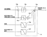
- FIG. 5 is a block diagram illustrating a configuration example of the repulsive force calculation unit 14 according to the lateral position.
- the repulsive force calculation unit 14 according to the lateral position includes a subtractor 14a, an upper / lower limiter 14b, a distance correction gain multiplication unit 14c, a lateral position feedback gain multiplication unit 14d, and a vehicle speed correction gain.
- a multiplier 14e and a curvature correction gain multiplier 14f are provided.
- the subtractor 14a subtracts the calculation result (distance from the vehicle A to the white road line (lateral position) at the front gazing point) output from the lateral position threshold (for example, 90 cm) determined in advance. . Then, the subtractor 14a outputs a subtraction result (hereinafter also referred to as a lateral position deviation) to the upper / lower limiter 14b. Thereby, the lateral position deviation becomes a positive value only when the distance from the vehicle A to the road white line at the forward gazing point is smaller than 90 cm (when it is on the adjacent lane side).
- the upper / lower limiter 14b performs upper / lower limiter processing on the calculation result (lateral position deviation) output from the subtractor 14a.
- the upper / lower limiter process for example, when the lateral position deviation is a positive value, a predetermined positive value is set, and when the lateral position deviation is a negative value, 0 is set.
- the upper / lower limiter 14b outputs the lateral position deviation after the upper / lower limiter process to the multiplier 14g.
- the lateral position deviation after the upper / lower limiter process becomes a positive value only when the distance from the vehicle A to the road white line at the forward gazing point is smaller than 90 cm (when it is on the adjacent lane side).
- the distance correction gain multiplication unit 14c multiplies the calculation result (lateral position at the front gazing point) output by the lateral position calculation unit 12c by the distance correction gain.
- the distance correction gain is, for example, the maximum value in the range from Y1 to Y2 (> Y1) from the vehicle A to the road white line (horizontal position), and the horizontal position in the range from Y2 to Y3 (> Y2). The larger the value is, the smaller the value becomes, and the minimum value is obtained when the lateral position is in the range of Y3 or more. Then, the distance correction gain multiplication unit 14c outputs the multiplication result (hereinafter also referred to as a corrected distance to the road white line) to the lateral position feedback gain multiplication unit 14d.
- the lateral position feedback gain multiplier 14d multiplies the calculation result (distance to the corrected road white line) output by the distance correction gain multiplier 14c by a predetermined lateral position feedback gain.
- the lateral position feedback gain is set to a value equal to or larger than a set value that can ensure responsiveness while avoiding a shortage of control amount.
- the lateral position feedback gain is set to a value less than a value at which the vehicle A vibrates and a value at which the driver feels neutral deviation. Further, the lateral position feedback gain is set to a value smaller than the yaw angle feedback gain. Then, the lateral position feedback gain multiplication unit 14d outputs the multiplication result to the multiplier 14g.
- the vehicle speed correction gain multiplier 14e multiplies the detection result (vehicle speed) output from the vehicle speed sensor 7a by a predetermined vehicle speed correction gain.
- the vehicle speed correction gain is, for example, the maximum value when the vehicle speed is in the range of 0 to 70 km / h, decreases as the vehicle speed increases within the range of the vehicle speed of 70 to 130 km / h, and the minimum value (for example, 0). Then, the vehicle speed correction gain multiplication unit 14e outputs the multiplication result to the multiplier 14g.
- the curvature correction gain multiplication unit 14f multiplies the detection result (curvature at the front gazing point) output from the curvature calculation unit 12b by a predetermined curvature correction gain.
- the curvature correction gain has a maximum value in the range of R1 to R2 (> R1) at the front gazing point, and decreases as the curvature increases in the range of R2 to R3 (> R2).
- the minimum value (for example, 0) is in the above range. Then, the curvature correction gain multiplication unit 14f outputs the multiplication result to the multiplier 14g.
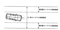
- FIG. 6 is a diagram illustrating an execution region of lateral position feedback control.
- the multiplier 14g multiplies the calculation results output from the lateral position feedback gain multiplication unit 14d, the vehicle speed correction gain multiplication unit 14e, and the curvature correction gain multiplication unit 14f. Then, the multiplier 14g outputs a multiplication result (hereinafter also referred to as a repulsive force according to the lateral position) to the adder 12d.
- the disturbance suppression command turning angle calculation unit 12 is only when the distance from the vehicle A to the road white line at the forward gazing point is smaller than 90 cm, that is, when it is on the adjacent lane side from the position 90 cm from the road white line.
- the vicinity of the center of the traveling lane is a region (dead zone) where the lateral position feedback control is not performed.
- the multiplier 14g (steering control part 10) can reduce the absolute value of the repulsive force according to a lateral position, so that the curvature in a front gaze point is large. Therefore, for example, when the vehicle A travels on a curve having a small curvature radius, the turning control unit 10 can reduce the repulsive force according to the lateral position. Therefore, the steering control unit 10 can suppress the steering of the left and right front wheels 5FL and 5FR in the direction in which the lateral position is reduced. As a result, the driver can drive the vehicle A along a route more appropriately.
- FIG. 7 is a block diagram illustrating a configuration example of the steering reaction force control unit 20.
- the steering reaction force control unit 20 includes a lateral force calculation unit 21, a lateral force offset unit 22, a subtractor 20a, a SAT calculation unit 23, an adder 20b, and a steering reaction force torque offset.
- a unit 24 and an adder 20c are provided.
- the lateral force calculation unit 21 estimates tire lateral force with reference to a steering angle-lateral force conversion map (MAP) based on detection results (steering angle, vehicle speed) output from the steering angle sensor 1d and the vehicle speed sensor 7a. .
- MAP steering angle-lateral force conversion map
- the lateral force calculation unit 21 estimates the tire lateral force based on the steering angle and the vehicle speed, and the steering angle-lateral force conversion map.
- the steering angle-lateral force conversion map is obtained by calculating the steering angle and the tire lateral direction for each vehicle speed in a conventional steering device (a steering device in which the steering unit 1 and the steering unit 2 are mechanically connected) calculated in advance through experiments or the like. It is a map showing the relationship with force.
- the larger the steering angle the greater the tire lateral force.
- the tire lateral force when the steering angle is small, the amount of change in the tire lateral force with respect to the amount of change in the steering angle is larger than when the steering angle is large.
- the tire lateral force is set to a smaller value as the vehicle speed is higher. Then, the lateral force calculation unit 21 outputs the calculation result to the subtracter 20a.
- the lateral force offset unit 22 calculates the lateral force offset amount based on the detection results (vehicle speed, white line information) output from the vehicle speed sensor 7a and the video processing unit 4a.
- the lateral force offset amount is an offset amount for offsetting a steering reaction force characteristic representing a steering reaction force torque corresponding to a self-aligning torque (SAT) generated by a tire lateral force.
- the self-aligning torque is a force (restoring force) generated by the road surface reaction force to return the wheel to a straight traveling state.
- the steering reaction force characteristic is a lateral force-steering reaction force conversion map used in the SAT calculation unit 23 described later.
- the lateral force offset amount is offset in the same sign direction as the self-aligning torque as the curvature of the road white line is larger. Then, the lateral force offset unit 22 outputs the calculation result to the subtracter 20a. Details of the lateral force offset unit 22 will be described later.
- the subtracter 20a subtracts the calculation result (lateral force offset amount) output by the lateral force offset unit 22 from the calculation result (tire lateral force) output by the lateral force calculation unit 21.
- the subtractor 20a has the same steering reaction force characteristic (a lateral force-steering reaction force conversion map described later) representing the steering reaction force torque according to the self-aligning torque generated by the tire lateral force as the self-aligning torque. It can be offset in the code direction.
- the subtracter 20 a outputs the subtraction result (tire lateral force after offset) to the SAT calculation unit 23.
- the SAT calculation unit 23 refers to the lateral force-steering reaction force conversion map based on the calculation result (tire lateral force after offset) output from the subtractor 20a, and the steering reaction force generated by the tire lateral force after offset. Calculate the torque. That is, the SAT calculation unit 23 calculates the steering reaction force torque generated by the offset tire lateral force based on the offset tire lateral force and the lateral force-steering reaction force conversion map. Then, the SAT calculation unit 23 outputs the calculation result (steering reaction force torque) to the adder 20b.
- the lateral force-steering reaction force conversion map is a map representing the relationship between the tire lateral force and the steering force torque in a conventional steering device calculated in advance through experiments or the like. That is, the lateral force-steering reaction force conversion map simulates a steering reaction force characteristic representing a steering reaction force torque according to a self-aligning torque generated by a tire lateral force in a conventional steering device.
- the steering reaction force torque is increased as the tire lateral force increases.
- the change amount of the steering reaction force torque with respect to the change amount of the tire lateral force is made larger when the tire lateral force is small than when it is large.
- the steering reaction force torque is set to a smaller value as the vehicle speed is higher.
- the adder 20b adds the steering reaction force torque component (spring term, viscosity term, inertia term) corresponding to the steering characteristic to the calculation result (steering reaction force torque) output from the SAT calculation unit 23.
- the spring term is a component proportional to the steering angle, and is calculated by multiplying the steering angle by a predetermined gain.
- the viscosity term is a component proportional to the steering angular velocity, and is calculated by multiplying the steering angular velocity by a predetermined gain.
- the inertia term is a component proportional to the steering angular acceleration, and is calculated by multiplying the steering angular acceleration by a predetermined gain. Then, the adder 20b outputs the addition result (steering reaction force torque + steering reaction force torque component) to the adder 20c.
- the steering reaction force torque offset unit 24 is based on the detection results (the turning angle, the vehicle speed, and the image of the traveling path ahead of the vehicle A) output by the turning angle sensor 2d, the vehicle speed sensor 7a, and the image processing unit 4a. Calculate the force offset amount.
- the steering reaction force offset amount is an offset amount for offsetting the steering reaction force characteristic (lateral force-steering reaction force conversion map) in the direction in which the steering reaction force torque increases.
- the steering reaction torque offset unit 24 determines whether the vehicle A corresponds to the steering amount of the steering wheel 1a by the driver.
- the steering reaction torque is offset in the direction of increasing.
- the vehicle speed is lower than the second threshold (for example, when the vehicle speed is less than 40 km / h)
- the steering reaction torque is offset in a direction in which the steering reaction torque increases as the turning angle increases.
- the first threshold value and the second threshold value are both reference values (set values) set in advance.
- the steering reaction torque offset unit 24 outputs the calculation result to the adder 20c. Details of the steering reaction torque offset unit 24 will be described later.
- the adder 20c adds the calculation result (steering reaction force offset amount) output from the steering reaction force torque offset unit 24 to the calculation result (steering reaction force torque + steering reaction force torque component) output from the adder 20b.
- the adder 20c outputs the addition result as a command steering reaction torque to the reaction force motor current driver 9a.
- FIG. 8 is a block diagram illustrating a configuration example of the lateral force offset unit 22.
- the lateral force offset unit 22 includes a curvature calculation unit 22a, an upper / lower limiter 22b, a SAT gain calculation unit 22c, a multiplier 22d, and a limiter processing unit 22e.
- the curvature calculation unit 22a Based on the detection result (white line information) output from the video processing unit 4a, the curvature calculation unit 22a calculates the curvature of the road white line at the forward gazing point (the road white line at the position of the vehicle A after the set time (0.5 seconds)). (Curvature). Then, the curvature calculator 22a outputs the calculation result to the multiplier 22d.
- the upper / lower limiter 22b performs upper / lower limiter processing on the detection result (vehicle speed) output from the vehicle speed sensor 7a.
- the vehicle speed increases as the vehicle speed increases in the range of 0 to V (> 0), and the maximum value is set in the range where the vehicle speed is V or higher.
- the upper / lower limiter 22b outputs the vehicle speed after the upper / lower limiter process to the SAT gain calculation unit 22c.
- the SAT gain calculation unit 22c calculates the SAT gain according to the vehicle speed based on the calculation result (vehicle speed after the limiter process) output by the upper / lower limiter 22b.
- the SAT gain corresponding to the vehicle speed increases as the vehicle speed increases in the range of 0 to 70 km / h, and reaches a maximum value in the range of 70 km / h or higher. Further, the SAT gain corresponding to the vehicle speed has a larger change amount of the SAT gain with respect to the change amount of the vehicle speed when the vehicle speed is high than when the vehicle speed is low. Then, the SAT gain calculation unit 22c outputs the calculation result to the multiplier 22d.
- the multiplier 22d multiplies the calculation result output from the curvature calculation unit 22a (curvature of the road white line at the forward gazing point) by the calculation result output from the SAT gain calculation unit 22c (SAT gain corresponding to the vehicle speed). Then, the multiplier 22d outputs the multiplication result as a lateral force offset amount to the limiter processing unit 22e. Thereby, the multiplier 22d can increase the lateral force offset amount as the curvature of the road white line at the forward gazing point is larger, that is, as the curvature radius of the road white line is smaller.
- the limiter processing unit 22e limits the maximum value of the calculation result (lateral force offset amount) output from the multiplier 22d and the upper limit of the change rate. The maximum value of the lateral force offset amount is 1000N. The upper limit of the rate of change of the lateral force offset amount is 600 N / s. Then, the limiter processing unit 22e outputs the limited lateral force offset amount to the subtracter 20a.
- FIG. 9 is a block diagram illustrating a configuration example of the steering reaction torque offset unit 24.
- the steering reaction torque offset unit 24 includes a yaw angle calculation unit 24 a, a lateral position calculation unit 24 b, a reaction force calculation unit 25 according to the departure allowance time, and a reaction force according to the lateral position.
- the calculation part 26, the reaction force calculation part 27 according to the turning angle, the reaction force selection part 24c, and the limiter process part 24d are provided.
- the yaw angle calculation unit 24a calculates a yaw angle (an angle between the road white line and the traveling direction of the vehicle A) at the forward gazing point based on the detection result (white line information) output from the video processing unit 4a. Then, the yaw angle calculator 24a outputs the calculation result to the reaction force calculator 25 corresponding to the departure allowance time.
- the lateral position calculation unit 24b determines the distance (lateral position) from the vehicle A to the road white line at the current position of the vehicle A based on the detection results (white line information and lane width information) output from the video processing unit 4a and the navigation system 17. ) (Hereinafter also referred to as a lateral position at the current position) and a lateral position at the front gazing point are calculated. Then, the lateral position calculation unit 24b outputs the calculation result to the reaction force calculation unit 25 corresponding to the departure allowance time and the reaction force calculation unit 26 corresponding to the lateral position.
- the reaction force calculation unit 25 corresponding to the departure allowance time includes detection results output by the vehicle speed sensor 7a, the yaw angle calculation unit 24a, and the lateral position calculation unit 24b (vehicle speed, yaw angle at the front gaze point, front gaze point, etc. Next, the reaction force corresponding to the deviation margin time is calculated. As the reaction force according to the departure allowance time, for example, there is a reaction force that increases as the departure allowance time is shorter. As the departure margin time, for example, there is a time (margin time) required for the vehicle A to depart from the travel lane. Then, the reaction force calculation unit 25 according to the departure allowance time outputs the calculation result to the reaction force selection unit 24c. Details of the reaction force calculation unit 25 according to the departure allowance time will be described later.
- the reaction force calculator 26 corresponding to the lateral position calculates a reaction force corresponding to the lateral position based on the calculation result (lateral position at the current position) output by the lateral position calculator 24b.
- the reaction force according to the lateral position for example, there is a reaction force that increases as the lateral position deviation increases.
- the lateral position deviation for example, there is a larger one of a distance from the vehicle A to the target left lateral position and a distance from the vehicle A to the target right lateral position.
- the target left lateral position for example, there is a position 90 cm from the left road white line to the road center side.
- the target right lateral position for example, there is a position 90 cm from the right road white line to the center of the road.
- the reaction force calculation unit 26 according to the lateral position outputs the calculation result to the reaction force selection unit 24c. Details of the reaction force calculation unit 26 according to the lateral position will be described later.
- the reaction force calculation unit 27 according to the turning angle calculates a reaction force according to the turning angle based on the detection results (the turning angle and the vehicle speed) output by the turning angle sensor 2d and the vehicle speed sensor 7a. As the reaction force according to the turning angle, for example, there is a reaction force that increases as the turning angle increases. And the reaction force calculating part 27 according to a turning angle outputs a calculation result to the reaction force selection part 24c. Details of the reaction force calculation unit 27 according to the turning angle will be described later.
- the reaction force selection unit 24c includes a detection result (vehicle speed) output from the vehicle speed sensor 7a, a calculation result output from the reaction force calculation unit 25 according to the departure allowance time (reaction force according to the departure allowance time), and a lateral position.
- the calculation result (reaction force according to the lateral position) output by the reaction force calculation unit 26 according to the angle and the calculation result (reaction force according to the steering angle) output by the reaction force calculation unit 27 according to the steering angle Based on the above, the optimum reaction force is selected. For example, when the vehicle speed is higher than the first threshold (for example, when the vehicle speed is 60 km / h or more), the reaction force selection unit 24c generates a reaction force according to the departure allowance time and a reaction force according to the lateral position.
- the one with the larger absolute value is selected.
- the reaction force selection unit 24c outputs the selection result to the limiter processing unit 24d as a steering reaction force offset amount.
- the limiter processing unit 24d limits the maximum value and the upper limit of the change rate of the selection result (steering reaction force offset amount) output by the reaction force selection unit 24c.
- the maximum value of the steering reaction force offset amount is 2 Nm.
- the upper limit of the change amount of the steering reaction force offset amount is 10 Nm / s.
- the limiter processing unit 24d outputs the steering reaction force offset amount after the limit to the adder 20c (see FIG. 7).
- FIG. 10 is a block diagram illustrating a configuration example of the reaction force calculation unit 25 according to the departure allowance time.
- the reaction force calculation unit 25 corresponding to the departure margin time includes a multiplier 25a, a divider 25b, a divider 25c, a departure margin time selection unit 25d, and a reaction corresponding to the departure margin time.
- a force calculator 25e The multiplier 25a multiplies the calculation result (yaw angle) output from the yaw angle calculation unit 24a by the vehicle speed. Then, the multiplier 25a outputs a multiplication result (hereinafter also referred to as a lateral speed of the vehicle A) to the divider 25b and the divider 25c.
- the divider 25b calculates the distance from the vehicle A to the left road white line at the forward gazing point (the horizontal position with respect to the left road white line) among the calculation results (the horizontal position at the current position) output by the horizontal position calculation unit 24b. Divide by the calculation result (lateral velocity) output from the multiplier 25a. Then, the divider 25b outputs the division result (hereinafter also referred to as a deviation margin time for the left road white line) to the deviation margin time selection unit 25d.
- the divider 25c calculates the distance (the horizontal position with respect to the right road white line) from the vehicle A to the right road white line at the front gazing point among the calculation results (the horizontal position at the current position) output by the horizontal position calculation unit 24b. Divide by the calculation result (lateral velocity) output from the multiplier 25a. Then, the divider 25b outputs the division result (hereinafter also referred to as a deviation margin time for the right road white line) to the deviation margin time selection unit 25d.
- the deviation margin time selection unit 25d selects the shorter one of the calculation result output from the divider 25b (deviation margin time for the left road white line) and the calculation result output from the divider 25c (deviation margin time for the right road white line). . Then, the departure allowance time selection unit 25d outputs the selection result (hereinafter also referred to as the departure allowance time) to the reaction force calculation unit 25e corresponding to the departure allowance time.
- the reaction force calculation unit 25e corresponding to the departure allowance time calculates a reaction force corresponding to the departure allowance time based on the calculation result (deviation allowance time) output from the departure allowance time selection unit 25d.
- the reaction force according to the deviation margin time becomes the lowest value (for example, almost 0) when the deviation margin time is 3 seconds or more, and increases as the deviation margin time is shorter within the range of 0 to 3 seconds ( It is a value inversely proportional to the deviation margin time). Then, the reaction force calculation unit 25e corresponding to the departure allowance time outputs the calculation result to the reaction force selection unit 24c (see FIG. 9) as a reaction force corresponding to the departure allowance time. Thereby, the reaction force according to the departure margin time increases as the departure margin time becomes shorter.
- FIG. 11 is a block diagram illustrating a configuration example of the reaction force calculation unit 26 according to the lateral position.
- the reaction force calculation unit 26 according to the lateral position includes a subtractor 26a, a subtractor 26b, a lateral position deviation selection unit 26c, and a reaction force calculation unit 26d according to the lateral position deviation.
- the subtractor 26a calculates a target left lateral position (a distance from the vehicle A to the left road white line at the current position of the vehicle A (a lateral position with respect to the left road white line)) output from the lateral position calculation unit 24b. For example, 90 cm) is subtracted.
- the subtractor 26a outputs a subtraction result (hereinafter also referred to as a lateral position deviation with respect to the left road white line) to the lateral position deviation selecting unit 26c.
- the subtractor 26b determines a target right lateral position (a distance from the vehicle A to the right road white line at the current position of the vehicle A (a lateral position with respect to the right road white line)) that is determined in advance from the calculation result output by the lateral position calculation unit 24b. For example, 90 cm) is subtracted. Then, the subtractor 26b outputs a subtraction result (hereinafter also referred to as a lateral position deviation with respect to the right road white line) to the lateral position deviation selecting unit 26c.
- the lateral position deviation selection unit 26c selects the larger one of the calculation result output from the subtractor 26a (lateral position deviation with respect to the left road white line) and the calculation result output from the subtractor 26b (lateral position deviation with respect to the right road white line). . Then, the lateral position deviation selection unit 26c outputs a selection result (hereinafter also referred to as a lateral position deviation) to the reaction force calculation unit 26d corresponding to the lateral position deviation.
- the reaction force calculation unit 26d corresponding to the lateral position deviation calculates a reaction force corresponding to the lateral position based on the calculation result (lateral position deviation) output by the lateral position deviation selection unit 26c.
- the reaction force according to the lateral position increases as the lateral position deviation increases in the range where the lateral position deviation is less than the set value, and reaches a maximum value in the range where the lateral position deviation is greater than or equal to the set value.
- the reaction force calculation unit 26d according to the lateral position deviation outputs the calculation result to the reaction force selection unit 24c (see FIG. 9) as a reaction force according to the lateral position.
- the reaction force according to the lateral position increases as the lateral position deviation increases.
- FIG. 12 is a block diagram illustrating a configuration example of the reaction force calculation unit 27 according to the turning angle.
- the reaction force calculation unit 27 according to the turning angle includes a feedforward axial force calculation unit 27a, a feedback axial force calculation unit 27b, a final axial force calculation unit 27c, and an axial force-steering reaction counter.
- a force converter 27d is provided.
- FIG. 13 is a block diagram illustrating a configuration of the feedforward axial force calculation unit 27a. As shown in FIG.
- the feedforward axial force calculating unit 27a is a steering angle ⁇ of the steering angle sensor 1d detects, and on the basis of the vehicle speed V vehicle speed sensor 7a detects, calculates the feedforward axial force T FF. Then, the feedforward axial force calculating unit 27a outputs the calculation result to the final axial force calculating unit 27c.
- the relational expression between the turning pinion angle ⁇ and the pinion axial force Th is based on an equation of motion of a vehicle including a steering mechanism in which the steering wheel 1a and the left and right front wheels 5FL and 5FR are mechanically connected ( 3) It is expressed by the formula.
- the steered pinion angle ⁇ for example, there is a rotation angle of the pinion shaft 2a.
- a rotation angle of the pinion shaft 2a for example, there is a multiplication value of a steering angle ⁇ and a variable gear ratio between the steering angle ⁇ and the turning angle ⁇ .
- the pinion axial force Th for example, there is a steering reaction force applied to the steering wheel 1a.
- the first term on the right side of the following equation (3) is a damping term representing a component based on the steered pinion angular velocity d ⁇ / dt among the components constituting the pinion axial force Th.
- the second term on the right side is an inertia term representing a component based on the turning pinion angular acceleration d2 ⁇ / dt2 among the components constituting the pinion axial force Th.
- the third term on the right side is a proportional term representing a component based on the tire lateral force Fd (steering pinion angle ⁇ ) among the components constituting the pinion axial force Th.
- Th Ks (Jrs 2 + Cr ⁇ s) / (Jr ⁇ s 2 + (Cr + Cs) s + Ks) ⁇ ⁇ + Cs (Jrs 3 + Cr ⁇ s 2 ) / (Jr ⁇ s 2 + (Cr + Cs) s + Ks) ⁇ ⁇ + (Ks + Cs ⁇ s) ) / (Jr ⁇ s 2 + (Cr + Cs) s + Ks) ⁇ Fd (3)
- Ks is pinion rigidity
- Cs is pinion viscosity
- Jr rack inertia
- Cr rack viscosity.
- the second term on the right side that is, the inertia term, contains a lot of noise components, and is preferably excluded because it induces vibration in the calculation result of the pinion axial force Th.
- f (V) for example, there is a function that changes according to the vehicle speed V. Therefore, the above equation (3) can be expressed as the following equation (4).
- Th Ks (Jrs 2 + Cr ⁇ s) / (Jr ⁇ s 2 + (Cr + Cs) s + Ks) ⁇ ⁇ + (Ks + Cs ⁇ s) / (Jr ⁇ s 2 + (Cr + Cs) s + Ks) ⁇ f (V) ⁇ ⁇ (4)
- a method of setting the variable f (V) for example, a method of reading the variable f (V) corresponding to the absolute value of the vehicle speed V from the control map M1 can be adopted.
- An example of the control map M1 is a map in which a variable f (V) corresponding to the absolute value of the vehicle speed V is registered. Specifically, the control map M1 sets the variable f (V) to a first set value (for example, 0.0) when the absolute value of the vehicle speed V is zero. Further, in the range where the absolute value of the vehicle speed V is equal to or higher than the first set vehicle speed V 1 (> 0), the variable f (V) is set to the second set value (> first set value. 1.0).
- control map M1 is a absolute value and a first predetermined vehicle speed V 1 lower than the range from 0 or more of the vehicle speed V is increased linearly variable f (V) in accordance with the absolute value of the steering angular velocity d [theta] / dt
- the control map M1 is a absolute value and a first predetermined vehicle speed V 1 lower than the range from 0 or more of the vehicle speed V, according to a linear function representing the relationship between the absolute value and the variable f of the vehicle speed V (V) Set the variable f (V).
- the linear function uses the variable f (V) as the first set value (0.0) when the absolute value of the vehicle speed V is 0, and the variable f when the absolute value of the vehicle speed V is the first set vehicle speed V 1.
- (V) be the second set value (1.0).
- feedforward axial force calculating unit 27a is the absolute value of the vehicle speed V is in the case of the first less than the set vehicle speed V 1 decreases the absolute value of the more proportional component having a small absolute value of the vehicle speed V (reduced ). Further, the feedforward axial force calculating unit 27a, when the absolute value of the vehicle speed V is first set vehicle speed V 1 or more, regardless of the size of the vehicle speed V, is not performed to reduce the absolute value of the proportional component.
- the pinion axial force Th that is, the steering reaction force generated in the steering wheel 1a can be expressed by the following equation (6) based on the above equation (5).
- Th P (s + 2 ⁇ ⁇ ⁇ ⁇ ⁇ n) / (s 2 + 2 ⁇ ⁇ ⁇ ⁇ n ⁇ s + ⁇ n 2 ) d ⁇ / dt + I ⁇ (s + 2 ⁇ ⁇ ⁇ ⁇ n) / (s 2 + 2 ⁇ ⁇ ⁇ ⁇ n ⁇ s + ⁇ n 2 ) ⁇ f ( V) ⁇ ⁇ (6)
- a method of setting the gain P 1 is, for example, can be employed a method of reading a gain P 1 corresponding to the absolute value of the steering angular velocity d? / Dt from the control map M2.
- the control map M2 for example, there is a map that has registered the gain P 1 corresponding to the absolute value of the steering angular velocity d? / Dt.
- the control map M2 is set to the gain P 1 third set value when the steering angular velocity d? / Dt is zero (e.g., 1.0).
- the gain P 1 is set to the fourth set value ( ⁇ The third set value is set to 0.5, for example. Further, in the control map M2, the gain P 1 is linearly changed according to the absolute value of the steering angular velocity d ⁇ / dt in the range where the absolute value of the steering angular velocity d ⁇ / dt is not less than 0 and less than the first set steering angular velocity d ⁇ 1 / dt. Decrease. Specifically, the control map M2, in absolute value range and less than the first set steering angular speed d?
- the feedforward axial force calculation unit 27a increases the damping component as the absolute value of the steering angular velocity d ⁇ / dt increases. Decrease the absolute value of (correct). Further, when the absolute value of the steering angular velocity d ⁇ / dt is greater than or equal to the first set steering angular velocity d ⁇ 1 / dt, the feedforward axial force calculation unit 27a gains P regardless of the magnitude of the steering angular velocity d ⁇ / dt. The absolute value of the damping component based on 1 is not corrected.
- the damping component included in the steering reaction force is saturated as the steering angular velocity d ⁇ / dt increases. Therefore, in the mechanical steering control device, when the damping component is saturated, the shape of the Lissajous figure composed of the steering angle ⁇ and the steering reaction force becomes constant regardless of the magnitude of the steering angular velocity d ⁇ / dt. However, in a steer-by-wire steering control device that does not consider saturation of the damping component included in the steering reaction force, the steering reaction force continues to increase as the steering angular velocity d ⁇ / dt increases.
- the reaction force calculation unit 27 according to the turning angle decreases the absolute value of the damping component as the absolute value of the steering angular velocity d ⁇ / dt increases. Therefore, the reaction force calculation unit 27 according to the turning angle can suppress an increase in the absolute value of the damping component when the steering angular velocity d ⁇ / dt is large. Therefore, the reaction force calculation unit 27 according to the turning angle can suppress an excessive damping component. Thereby, the reaction force calculation part 27 according to a turning angle can provide a more suitable steering feeling.
- the control map M3 is the gain P 2 fifth set value when the absolute value of the vehicle speed V is zero (e.g., 0.5) is set to.
- the gain P 2 is set to the sixth set value (> 5th set value regardless of the magnitude of the vehicle speed V. For example, 1. Set to 0).
- control map M3 is the absolute value and the second predetermined vehicle speed V 2 less than the range from 0 or more of the vehicle speed V is linearly increasing gain P 2 in accordance with the absolute value of the vehicle speed V.
- the control map M3 is the absolute value and the second predetermined vehicle speed V 2 less than the range from 0 or more of the vehicle speed V, the gain P according to a linear function representing the relationship between the absolute value and the gain P 2 of the vehicle speed V 2 is set. Linear function, when the absolute value of the vehicle speed V is zero the gain P 2 fifth set value and (0.5), when the absolute value of the vehicle speed V is a second set speed V 2 of the gain P 2 The sixth set value (1.0) is assumed.
- feedforward axial force calculating unit 27a is the absolute value of the vehicle speed V is in the case of the second lower than the set vehicle speed V 2, the smaller the absolute value of the more damping component having a small absolute value of the vehicle speed V (corrected ). Further, the feedforward axial force calculating unit 27a, when the absolute value of the vehicle speed V is a second set speed V 2 or greater, regardless of the size of the vehicle speed V, the absolute value of the damping component based on the gain P 2 Do not make corrections.
- the reaction force calculation unit 27 according to the turning angle decreases the absolute value of the damping component as the absolute value of the vehicle speed V decreases.
- the reaction force calculation unit 27 according to the turning angle can reduce the steering reaction force by reducing the absolute value of the damping component as the absolute value of the vehicle speed V decreases.
- the reaction force calculation part 27 according to a turning angle can provide a more suitable steering feeling.
- a method of setting the correction damping component for example, a method of reading the correction damping component corresponding to the absolute value of the steering angular velocity d ⁇ / dt from the control map M4 can be adopted.
- An example of the control map M4 is a map in which a correction damping component corresponding to the absolute value of the steering angular velocity d ⁇ / dt is registered. Specifically, the control map M4 is set for each vehicle speed V. Each control map M4 sets the correction damping component to the seventh set value (for example, 0.0) when the steering angular velocity d ⁇ / dt is zero.
- control map M4 indicates that the correction damping component is used regardless of the magnitude of the steering angular velocity d ⁇ / dt in the range where the absolute value of the steering angular velocity d ⁇ / dt is equal to or greater than the second set steering angular velocity d ⁇ 2 / dt (> 0).
- the steering angular velocity d ⁇ / dt is 0.0 or more and the absolute value of the steering angular velocity d ⁇ / dt is the third set steering angular velocity d ⁇ 3 / dt (0 ⁇ d ⁇ 3 / dt ⁇ d ⁇ 2 / dt).
- the correction damping component is linearly increased according to the absolute value of the steering angular velocity d ⁇ / dt.
- the absolute value of the steering angular velocity d ⁇ / dt and the correction damping are set in a range where the absolute value of the steering angular velocity d ⁇ / dt is not less than 0 and less than the third set steering angular velocity d ⁇ 3 / dt.
- a correction damping component is set according to a linear function representing the relationship with the component.
- the correction damping component is linearly increased according to the value.
- the control map M4 indicates that the absolute value of the vehicle speed V is within a range where the absolute value of the steering angular velocity d ⁇ / dt is greater than or equal to the third set steering angular velocity d ⁇ 3 / dt and less than the second set steering angular velocity d ⁇ 2 / dt.
- the correction damping component is set according to a linear function representing the relationship between the correction damping component and the correction damping component.
- the correction damping component is the ninth set value
- the absolute value of the steering angular velocity d ⁇ / dt is the second set steering.
- the correction damping component is set to the eighth set value.
- the feedforward axial force calculating unit 27a when the absolute value of the steering angular velocity d? / Dt is the second set steering angular velocity d? 2 / dt or more, regardless of the magnitude of the steering angular velocity d? / Dt, correction
- the absolute value of the damping component is set to a predetermined constant value.
- the reaction force calculation unit 27 according to the turning angle adds a correction damping component absolute value larger the absolute value of the steering angular velocity d? / Dt increases feedforward axial force T FF. Therefore, the reaction force calculation unit 27 according to the turning angle can increase the rising of the steering reaction force when the absolute value of the steering angular velocity d ⁇ / dt increases at the start of turning of the steering wheel 1a. Thereby, the reaction force calculation part 27 according to a turning angle can provide a more suitable steering feeling.
- the reaction force calculation unit 27 corrects a predetermined constant value when the absolute value of the steering angular velocity d ⁇ / dt is equal to or greater than the second set steering angular velocity d ⁇ 2 / dt of 7 for correction. Ingredients. Therefore, when the driver turns off the steering wheel 1a and the absolute value of the steering angular velocity d ⁇ / dt becomes equal to or higher than the second set steering angular velocity d ⁇ 2 / dt, fluctuations in the correction damping component can be suppressed. . Therefore, the reaction force calculation unit 27 according to the turning angle does not sense the change in the steering reaction force due to the fluctuation of the correction damping component, and can prevent the driver from feeling uncomfortable with the steering feeling.
- FIG. 14 is a block diagram illustrating a configuration of the feedback axial force calculation unit 27b.
- the feedback axial force calculation unit 27b includes a current axial force calculation unit 27ba, a blend axial force calculation unit 27bb, a steering angular velocity detection unit 27bc, a steering determination unit 27bd, and a feedback axial force calculation execution unit 27be.
- the current axial force calculation unit 27ba calculates the steering rack axial force according to the following equation (8) based on the detection result (steering angle) output by the steering angle sensor 2d.
- the steering current varies when the steering wheel 1a is steered, the target turning angle ⁇ * varies, and a difference occurs between the target turning angle ⁇ * and the actual turning angle ⁇ .
- the left and right front wheels 5FL and 5FR are steered, the tire lateral force Fd acts on the left and right front wheels 5FL and 5FR, and there is a difference between the target turning angle ⁇ * and the actual turning angle ⁇ . It also varies depending on.
- the turning current causes road surface disturbance to the left and right front wheels 5FL and 5FR due to road surface unevenness and the like
- the tire lateral force Fd acts to the left and right front wheels 5FL and 5FR
- the target turning angle ⁇ * and the actual turning angle ⁇ It also fluctuates due to the difference between the two. Therefore, the feedback axial force calculation unit 27b can calculate the steering rack axial force (current axial force) reflecting the influence of the tire lateral force Fd acting on the left and right front wheels 5FL and 5FR based on the steering current.
- the current axial force is generated when a difference occurs between the target turning angle ⁇ * and the actual turning angle ⁇ . For this reason, the phase of the current axial force advances as compared with the actual steering rack axial force and lateral G axial force.
- the blend axial force calculation unit 27bb calculates a steering rack axial force (hereinafter also referred to as a lateral G-axis force) according to the following equation (9).
- a steering rack axial force hereinafter also referred to as a lateral G-axis force
- the front wheel load and the lateral acceleration Gy are multiplied, and the multiplication result is calculated as the axial force (axial force) applied to the left and right front wheels 5FL, 5FR.
- the calculated axial force applied to the left and right front wheels 5FL and 5FR is multiplied by a constant (hereinafter also referred to as a link ratio) according to the link angle and suspension, and the multiplication result is represented by the horizontal G Calculated as axial force.
- Lateral G axial force Axial force applied to left and right front wheels 5FL, 5FR x link ratio (9)
- Axial force applied to left and right front wheels 5FL, 5FR front wheel load x lateral acceleration Gy
- the blend axial force calculation unit 27bb can calculate the steering rack axial force (lateral G axial force) reflecting the influence of the tire lateral force Fd acting on the left and right front wheels 5FL, 5FR based on the lateral acceleration Gy.
- the acceleration sensor 7b is disposed on the spring (vehicle body)
- detection of the lateral acceleration Gy is delayed. For this reason, the phase of the lateral G-axis force is delayed compared to the actual steering rack axial force.
- the lateral acceleration Gy detected by the acceleration sensor 7b is used when calculating the lateral G-axis force is shown, but other configurations may be adopted.
- the yaw rate ⁇ detected by the yaw rate sensor 7c may be multiplied by the vehicle speed V detected by the vehicle speed sensor 7a, and the multiplication result ⁇ ⁇ V may be used instead of the lateral acceleration Gy.
- the blend axial force calculation unit 27bb is based on the vehicle speed V detected by the vehicle speed sensor 7a and the yaw rate ⁇ detected by the yaw rate sensor 7c, according to the following equation (10), and the steering rack axial force (hereinafter also referred to as the yaw rate axial force). Is calculated.
- the front wheel load, the vehicle speed V, and the yaw rate ⁇ are multiplied, and the multiplication result is calculated as the axial force applied to the left and right front wheels 5FL, 5FR.
- the blend axial force calculation unit 27bb can calculate the steering rack axial force (yaw rate axial force) reflecting the influence of the tire lateral force Fd acting on the left and right front wheels 5FL and 5FR based on the yaw rate ⁇ .
- the yaw rate sensor 7c is disposed on the spring (vehicle body), detection of the yaw rate ⁇ is delayed. For this reason, the phase of the yaw rate axial force is delayed compared to the actual steering rack axial force.
- the blend axial force calculation unit 27bb reads the current axial force from the current axial force calculation unit 27ba. Subsequently, the blend axial force calculation unit 27bb determines the steering rack axial force (hereinafter referred to as “blend axial force”) according to the following equation (11) based on the read current axial force and the calculated lateral G axial force and yaw rate axial force. TBR is calculated. In the following equation (11), the lateral G-axis force is multiplied by the distribution ratio K1, the current axial force is multiplied by the distribution ratio K2, the yaw rate axial force is multiplied by the distribution ratio K3, and the sum of these multiplication results is the blend axis. Calculated as force TBR .
- the blend axial force TBR is calculated based on a value obtained by multiplying the lateral G axial force by the distribution ratio K1, a value obtained by multiplying the current axial force by the distribution ratio K2, and a value obtained by multiplying the yaw rate axial force by the distribution ratio K3. .
- the blend axial force calculation unit 27bb outputs the calculation result to the steering determination unit 27bd and the feedback axial force calculation execution unit 27be.
- the blend axial force T BR is a positive value for the axial force that directs the left and right front wheels 5FL, 5FR in the right direction, and a negative value for the axial force that directs the left and right front wheels 5FL, 5FR in the left direction.
- T BR lateral G axial force ⁇ K1 + current axial force ⁇ K2 + yaw rate axial force ⁇ K3 (11)
- the distribution ratios K1, K2, and K3 are distribution ratios of the lateral G-axis force, current axial force, and yaw rate axial force.
- the magnitude relationship between the distribution ratios K1, K2, and K3 is K1>K2> K3. That is, the distribution ratio is set to a large value in the order of the lateral G axial force, the current axial force, and the yaw rate axial force.
- blending axial force calculating unit 27bb as a blend axial force T BR, the right and left front wheels 5FL, calculates a steering rack axial force that reflects the influence of the tire lateral force Fd acting on 5FR.
- the blend axial force calculating unit 27bb calculates the blending axial force T BR on the basis of the value obtained by multiplying the distribution ratio K1 in the current axial force value and the lateral G axial force multiplied by the distribution ratio K2 to.
- the lateral G axial force is delayed in phase as compared with the actual steering rack axial force.
- the phase of the current axial force advances compared to the actual steering rack axial force. Therefore, the blend axial force calculating unit 27bb, by adding the current axial force to the lateral G axial force, lateral G axial force due to the phase lag can be compensated for, can be calculated more appropriate blend axial force T BR. Therefore, the SBW controller 4 can apply a more appropriate steering reaction force by driving the reaction force motor 1c based on the blend axial force TBR .
- axial force calculating section 27bb calculates the blending axial force T BR on the basis of the value obtained by multiplying the distribution ratio K1 in the current axial force value and the lateral G axial force multiplied by the distribution ratio K2 to.
- the vehicle A has a target turning angle ⁇ * and an actual turning angle. There is a difference with ⁇ .
- the blend axial force calculating unit 27bb by adding the current axial force to the lateral G axial force, the left and right front wheels 5FL, can reflect the influence of the road surface disturbance acting on the blend axial force T BR in 5FR, more appropriate blend The axial force T BR can be calculated. Therefore, the SBW controller 4 can apply a more appropriate steering reaction force by driving the reaction force motor 1c based on the blend axial force TBR .
- the blend axial force calculation unit 27bb makes the lateral G axial force distribution ratio K1 larger than the current axial force distribution ratio K2. Therefore, the blend axial force calculating unit 27bb can reduce the distribution ratio of the current axial force. For example, even if the estimation accuracy of the current axial force decreases due to the inertia of the steering motor 2c or the influence of friction, the blend axial force T A decrease in BR estimation accuracy can be suppressed. Therefore, the SBW controller 4 can apply a more appropriate steering reaction force by driving the reaction force motor 1c based on the blend axial force TBR .
- the blend axial force calculation unit 27bb is based on a value obtained by multiplying the current axial force by the distribution ratio K2, a value obtained by multiplying the lateral G axial force by the distribution ratio K1, and a value obtained by multiplying the yaw rate axial force by the distribution ratio K3.
- a feedback axial force T FB is calculated.
- the steering current and the lateral acceleration Gy increase, so that the detection result of the acceleration sensor 7b and the detection result of the steering current detection unit 8B are both maximum values. (Saturated value).
- the SBW controller 4 can apply a more appropriate steering reaction force by driving the reaction force motor 1c based on the blend axial force TBR .
- the steering angular velocity detector 27bc calculates the steering angular velocity d ⁇ / dt of the steering wheel 1a based on the steering angle ⁇ detected by the steering angle sensor 1d. Then, the steering angular velocity detection unit 27bc outputs the calculation result to the blend axial force calculation unit 27bb and the steering determination unit 27bd.
- the steering angular velocity d ⁇ / dt has a positive value when the steering wheel 1a rotates clockwise, and a negative value when the steering wheel 1a rotates counterclockwise.
- Steering determining section 27bd based on the steering angular velocity d? / Dt which blends axial force blends axial force calculating unit 27bb calculated T BR and steering angular velocity detection unit 27bc detects, turning-increasing operation and off the driver's steering wheel 1a It is determined which of the return operations is being performed.
- the rounding-up operation is, for example, a steering operation in a direction in which the steering wheel 1a (steering angle ⁇ ) is away from the neutral position. Further, as the switching back operation, for example, there is a steering operation in a direction in which the steering wheel 1a (steering angle ⁇ ) approaches the neutral position.
- the steering judging portion 27bd when and steering angular velocity d? / Dt blend axial force T BR is positive value is positive, or a blend axial force T BR negative value and the steering angular velocity d? / If dt is a negative value, it is determined that the steering wheel 1a is being increased, and the variable K4 is set to 1.0.
- the variable K4 is a flag that indicates whether the steering wheel 1a is being turned on or turned off.
- the variable K4 is set to 1.0 when the steering wheel 1a is being increased, and is set to 0.0 when the return operation is being performed.
- the steering judging portion 27bd, the blend axial force T BR is positive value and when the steering angular velocity d?
- / Dt is negative value, or a blend axial force T BR negative value and the steering angular velocity d? / Dt is positive If it is a value, it is determined that the steering wheel 1a is not being increased, and the variable K4 is set to zero. Then, the steering determination unit 27bd outputs the set variable K4 to the feedback axial force calculation execution unit 27be.
- the feedback axial force calculation execution unit 27be includes a current axial force calculation unit 27ba, a blend axial force calculation unit 27bb, a steering angular velocity detection unit 27bc, and a steering determination unit 27bd, so that the current axial force, blend axial force T BR , steering angular velocity d ⁇ / dt, and Read variable K4. Subsequently, the feedback axial force calculating execution unit 27be is read current axial force, based on the blend axial force T BR, the steering angular velocity d? / Dt and variables K4, the following (12) steering rack shaft force according to equation (hereinafter, the feedback shaft Force T FB ) is calculated. Then, the feedback axial force calculation execution unit 27be outputs the calculation result to the final axial force calculation unit 27c.
- Feedback axial force T FB current axial force ⁇ GB + blend axial force T BR ⁇ (1 ⁇ GB) (12)
- GB is a numerical value (hereinafter referred to as a distribution ratio) representing a distribution ratio GB of the current axial force and a distribution ratio (1-GB) of the blend axial force TBR .
- the feedback axial force calculating execution unit 27be based on the distribution ratio GB, GB and current axial force blended axial force T BR: by combined at a ratio of (1-GB), the feedback axial force T FB calculate.
- a setting method of the distribution ratio GB for example, a method of setting the distribution ratio GB by the distribution ratio setting unit 27bf based on the determination result output by the steering determination unit 27bd can be adopted.
- K5 is a numerical value that represents the distribution ratio GB of the current axial force and the distribution ratio (1-GB) of the blend axial force TBR when K4 is 1.0, that is, when the steering wheel 1a is increased. is there.
- the feedback axial force calculating execution unit 27be during turning-increasing operation of the steering wheel 1a, current axial force based on the variable K5 blended axial force T BR and the K5: by combined at a ratio of (1-K5)
- the feedback axial force T FB is calculated. Note that when K4 is 0.0, i.e., at the time of switching back operation of the steering wheel 1a, regardless of variable K5, the blend axial force T BR feedback axial force T FB.
- a setting method of the variable K5 for example, a method of reading the variable K5 corresponding to the steering angular velocity d ⁇ / dt from the control map M5 can be adopted.
- An example of the control map M5 is a map in which a variable K5 corresponding to the steering angular velocity d ⁇ / dt is registered.
- the variable K5 is set regardless of the magnitude of the steering angular velocity d ⁇ / dt.
- the tenth set value (for example, 1.0) is set.
- the control map M5 has a variable K5 in the range where the absolute value of the steering angular velocity d ⁇ / dt is not less than the fifth set steering angular velocity d ⁇ 5 / dt (> d ⁇ 4 / dt) regardless of the magnitude of the steering angular velocity d ⁇ / dt.
- the control map M5 indicates that the absolute value of the steering angular velocity d ⁇ / dt is within a range where the absolute value of the steering angular velocity d ⁇ / dt is not less than the fourth set steering angular velocity d ⁇ 4 / dt and less than the fifth set steering angular velocity d ⁇ 5 / dt. Accordingly, the variable K5 is linearly decreased.
- control map M5 indicates that the steering angular velocity d ⁇ / dt is within a range where the absolute value of the steering angular velocity d ⁇ / dt is not less than the fourth set steering angular velocity d ⁇ 4 / dt and less than the fifth set steering angular velocity d ⁇ 5 / dt.
- the variable K5 is set according to a linear function that represents the relationship between the absolute value of and When the absolute value of the steering angular velocity d ⁇ / dt is the fourth set steering angular velocity d ⁇ 4 / dt, the linear function sets the variable K5 to the tenth set value (1.0), and the absolute value of the steering angular velocity d ⁇ / dt is the first
- the variable K5 is set to the eleventh set value (0.0) when the 5-set steering angular velocity is d ⁇ 5 / dt.
- the distribution ratio setting unit 27bf has the variable K4 of 1.0 (during the addition operation) and the absolute value of the steering angular velocity d ⁇ / dt is less than the fourth set steering angular velocity d ⁇ 4 / dt (during low-speed steering). ),
- the distribution ratio GB is set to 1.0.
- the feedback axial force calculating execution unit 27be is a feedback axial force T FB current axial force.
- the distribution ratio setting unit 27bf has a variable K4 of 1.0 (during an increase operation), and the absolute value of the steering angular velocity d ⁇ / dt is equal to or greater than the fifth set steering angular velocity d ⁇ 5 / dt (during high-speed steering).
- the distribution ratio GB is set to 0.0.
- the feedback axial force calculating execution unit 27be is a blend axial force T BR feedback axial force T FB.
- the distribution ratio setting unit 27bf has a variable K4 of 1.0 (during a rounding operation), the absolute value of the steering angular velocity d ⁇ / dt is equal to or greater than the fourth set steering angular velocity d ⁇ 4 / dt, and the fifth setting. If the steering angular velocity is less than d ⁇ 5 / dt (during medium-speed steering), the variable K5 is set as the distribution ratio GB.
- the feedback axial force calculating execution unit 27be includes a feedback axial force T FB what the sum of the value obtained by multiplying the (1-K5) to the value blended axial force T BR multiplied by variable K5 current axial force To do.
- the distribution ratio setting unit 27bf sets 0.0 as the distribution ratio GB regardless of the steering angular velocity d ⁇ / dt. Then, the feedback axial force calculating execution unit 27be is a blend axial force T BR feedback axial force T FB.
- the feedback axial force calculation execution unit 27be performs the following operation when the absolute value of the steering angular velocity d ⁇ / dt is less than the fourth set steering angular velocity d ⁇ 4 / dt.
- the current axial force is defined as a feedback axial force TFB .
- TFB feedback axial force
- the SBW controller 4 can apply a steering reaction force that returns the steering wheel 1a to the neutral position, similarly to the mechanical steering control device, by setting the current axial force to the feedback axial force TFB .
- the SBW controller 4 can apply a more appropriate steering reaction force when the steering wheel 1a is increased.
- the blend axial force T BR is the left and right front wheels 5FL, contains no elements of the friction caused by the turning of 5FR.
- the feedback axial force calculation execution unit 27be presets the current axial force and the lateral G-axis force regardless of the absolute value of the steering angular velocity d ⁇ / dt.
- the blend axial force TBR distributed at the distributed ratio is set as the feedback axial force TFB .
- the driver when the steering wheel 1a is switched back, the driver reduces the holding force of the steering wheel 1a and slides the steering wheel 1a with the palm of the hand, thereby making the steering wheel 1a neutral.
- the left and right front wheels 5FL and 5FR were returned to the neutral position.
- the feedback axial force calculation execution section 27Be by blending axial force T BR feedback axial force T FB, turning current is reduced, as the current shaft power is reduced, neutral steering wheel 1a It can suppress that the steering reaction force which returns to a position reduces.
- the feedback axial force calculation execution unit 27be reduces the holding force of the steering wheel 1a so that the driver can slide the steering wheel 1a with the palm of the hand to neutralize the steering wheel 1a, like the mechanical steering control device. Can be returned to position. Thereby, the SBW controller 4 can give a more appropriate steering reaction force when the steering wheel 1a is switched back.
- the feedback axial force calculation execution unit 27be determines that the steering wheel 1a is being increased, and the absolute value of the steering angular velocity d ⁇ / dt is equal to or greater than the fourth set steering angular velocity d ⁇ 4 / dt.
- the feedback axial force calculation execution unit 27be for example, when the steering angle ⁇ straddles the neutral position during the switching back operation of the steering wheel 1a, and the steering wheel 1a is continuously increased in the same direction.
- the SBW controller 4 can provide a more appropriate steering reaction force.
- the final axial force calculation unit 27c includes the steering angle ⁇ , the vehicle speed V, the lateral direction from the steering angle sensor 1d, the vehicle speed sensor 7a, the acceleration sensor 7b, the feedforward axial force calculation unit 27a, and the feedback axial force calculation unit 27b.
- acceleration Gy reads the feedforward axial force T FF and the feedback axial force T FB.
- the final axial force calculation unit 27c calculates the steering angular velocity d ⁇ / dt of the steering wheel 1a based on the read steering angle ⁇ .
- the final axial force calculating section 27c based on the read steering angle [delta], the vehicle speed V, the lateral acceleration Gy, feedforward axial force T FF and the feedback axial force T FB, calculated steering angular velocity d? / Dt, the following ( 14)
- the steering rack axial force (hereinafter referred to as final axial force) is calculated according to the equation (14).
- the final axial force calculation unit 27c outputs the calculation result to the axial force-steering reaction force conversion unit 27d.
- Final axial force feed forward axial force T FF ⁇ GF + feedback axial force T FB ⁇ (1-GF) (14)
- GF is a numerical value representing a distribution ratio of the distribution ratio GF and the feedback axial force T FB feedforward axial force T FF (1-GF) (hereinafter, referred to as distribution ratio) is.
- the final axial force calculating section 27c based on the distribution ratio GF, the feedforward axial force T FF and the feedback axial force T FB GF: by combined at a ratio of (1-GF), the final axial force calculate.
- the final axial force calculation unit 27c calculates the final axial force based on the feedback axial force TFB and the feedforward axial force TFF .
- the feedback axial force T FB changes according to a change in the road surface state or a change in the vehicle state in order to reflect the influence of the tire lateral force Fd acting on the left and right front wheels 5FL, 5FR.
- the feedforward axial force T FF since not reflect the influence of tire lateral force Fd, smoothly changes regardless of the change or the like of the road surface condition. Therefore, the final axial force calculating section 27c in addition to the feedback axial force T FB, it calculates the final axial force on the basis of the feedforward axial force T FF, it can be calculated more appropriate final axial force.
- the final axial force calculation unit 27c includes a distribution ratio calculation unit 27ca.
- the distribution ratio calculation unit 27ca distributes the distribution ratio GF 1 based on the axial force difference, the distribution ratio GF 2 based on the lateral acceleration Gy, the distribution ratio GF 3 based on the vehicle speed V and the steering angle ⁇ , and the distribution based on the steering angular speed d ⁇ / dt. based on the ratio GF 4, it sets the distribution ratio GF.
- the axial force difference for example, a difference between the feedforward axial force TFF and the feedback axial force TFB can be adopted. Specifically, the axial force difference, a subtraction result obtained by subtracting the feedback axial force T FB from the feedforward axial force T FF.
- the distribution ratio GF As a method for setting the distribution ratio GF, for example, based on the smaller one of the distribution ratio GF 1 based on the axial force difference and the distribution ratio GF 2 based on the lateral acceleration Gy, the vehicle speed V, and the steering angle ⁇ .
- the distribution ratio GF 3 by multiplying the allocation ratio GF 4 based on the steering angular velocity d? / dt, can be adopted a method for the distribution ratio GF multiplication results.
- the axial force-steering reaction force conversion unit 27d calculates a target steering reaction force based on the final axial force calculated by the final axial force calculation unit 27c.
- the target steering reaction force is a target value of the steering reaction force.
- a method for calculating the target steering reaction force for example, a method of reading the target steering reaction force corresponding to the vehicle speed V and the final axial force from the control map M6 can be adopted.
- the control map M6 there is a map in which a target steering reaction force corresponding to the final axial force is registered for each vehicle speed V.
- the control map M6 is set for each vehicle speed V. In the control map M6, the target steering reaction force is increased as the final axial force increases.
- the axial force-steering reaction force conversion unit 27d outputs the calculation result to the reaction force selection unit 24c (see FIG. 9) as a reaction force according to the turning angle. Thereby, the reaction force according to the turning angle increases as the turning angle increases.
- FIG. 15 is a flowchart regarding processing in the reaction force selection unit 24c.
- the reaction force selection unit 24c outputs the calculation result (reaction force according to the deviation allowance time) output from the reaction force calculation unit 25 according to the departure allowance time and the calculation result output from the reaction force calculation unit 26 according to the lateral position.
- the one with the larger absolute value is selected from (the reaction force according to the lateral position), and is set as the first reaction force command value (step S101).
- the reaction force selection unit 24c uses the calculation result (reaction force according to the turning angle) output from the reaction force calculation unit 27 according to the turning angle as the second reaction force command value (step S102). . Further, the reaction force selection unit 24c calculates values of the first switching gain and the second switching gain based on the detection result (vehicle speed) output from the vehicle speed sensor 7a (step S103).
- the first switching gain is 1 and the second switching gain is 0.
- the first switching gain is 0 and the second switching gain is 0.
- the first switching gain and the second switching gain are each in the range of 0 to 1, and the total value of both values is always 1. Fluctuate within the range.
- the first switching gain and the second switching gain indicate a ratio (ratio) according to the vehicle speed.
- the first switching gain indicates a ratio occupied by the first reaction force command value.
- the second switching gain indicates a ratio occupied by the second reaction force command value.
- the reaction force selection unit 24c adds the value obtained by multiplying the first reaction force command value by the first switching gain and the value obtained by multiplying the second reaction force command value by the second switching gain.
- a steering reaction force offset amount is calculated (step S104).
- the second reaction force command value is selected in the high speed range
- the first reaction force command value is selected in the low speed range
- the first reaction force command value is selected between the low speed range and the high speed range according to the ratio of the switching gain.
- the reaction force command value and the second reaction force command value can be blended (mixed).
- the reaction force selection unit 24c outputs the calculated steering reaction force offset amount to the limiter processing unit 24d (see FIG. 9) (step S105).
- reaction force calculation unit 25 is: While calculating 1st reaction force command value, the reaction force command value calculation part which calculates 2nd reaction force command value is formed.
- FIG. 16 is a diagram illustrating a vehicle situation and a control map when the vehicle A approaches the end of the lane.
- FIGS. 16A and 16B are views showing a vehicle situation and a control map when the vehicle A approaches the right end of the lane.
- the content shown to FIG. 16 (a), (b) will be reversed horizontally.
- the first reaction force command value changes as shown in the control map of the reaction force command shown in FIG.
- the second reaction force command value changes as shown in the reaction force command control map shown in FIG.
- reaction force selection unit 24c calculates the values of the first switching gain and the second switching gain according to the vehicle speed, and then sets the first reaction force command value as shown in FIG.
- a steering reaction force offset amount is calculated by adding a value obtained by multiplying the first switching gain and a value obtained by multiplying the second reaction force command value by the second switching gain. Thereby, the reaction force selection unit 24c can appropriately select the first reaction force command value and the second reaction force command value according to the vehicle speed.
- FIG. 17 is a diagram illustrating the lane keeping control when the vehicle A is traveling in a high speed range with a constant yaw angle with respect to the lane.
- the change amount of the steering angle (steering wheel angle) is small compared to the low speed range, and the steering angle is easily returned straight (neutral position).
- the vehicle response is good with respect to the steering angle, and there is not much delay in the change of the lateral position. Therefore, in the high speed range, the control performance is good only with the reaction force according to the lateral position.
- FIG. 18 is a diagram illustrating lane keeping control in the case where the vehicle speed of the vehicle A is in the low speed range and traveling with a constant yaw angle with respect to the lane.
- the amount of change in the steering angle is larger than in the high speed range, and it is difficult to return the steering angle to straight ahead.
- the vehicle response is poor with respect to the steering angle, and a significant delay occurs in the change in the lateral position. Therefore, in the low speed range, hunting (disturbance) is likely to occur if the reaction force is controlled only in accordance with the lateral position.
- the control result is improved by performing the lane keeping control according to the present embodiment.
- the reaction force selection unit 24c can calculate the steering reaction force offset amount by any one of the following methods (1) to (5) regardless of the first and second switching gains. It is. At this time, either a method for calculating the steering reaction force offset amount using the first and second switching gains described above or one of the following methods (1) to (5) is selected based on a prior setting or the like. It may be possible. However, actually, it is not limited to these methods.
- (2) Total value The reaction force selection unit 24c adds the first reaction force command value and the second reaction force command value when the vehicle speed is lower than the second threshold value, and performs a steering reaction according to the addition result. Calculate the force offset amount.
- the reaction force selection unit 24c determines that the rotation direction of the steering wheel (the direction of the driver's steering input, etc.) moves the vehicle A to the lane center side (deviation avoidance side).
- the method (1) and the method (2) are switched depending on whether the direction is close.
- the reaction force selection unit 24c is configured such that the rotation direction of the steering wheel is a direction that brings the vehicle A toward the lane center side (deviation avoidance side) (the rotation direction of the steering wheel is the same direction as the steering reaction force direction). Performs a select high of the first reaction force command value and the second reaction force command value to calculate the steering reaction force offset amount.
- the reaction force selection unit 24c is configured so that the rotation direction of the steering wheel is a direction that brings the vehicle A toward the lane edge (departure side) (the rotation direction of the steering wheel is different from the direction of the steering reaction force).
- the steering reaction force offset amount is calculated by adding the first reaction force command value and the second reaction force command value.
- the reaction force selection unit 24c calculates an average value of the first reaction force command value and the second reaction force command value, and according to the calculation result The steering reaction force offset amount is calculated.
- the reaction force selection unit 24c calculates an average value by dividing the sum of the first reaction force command value and the second reaction force command value by two. Therefore, actually, the method (4) is an embodiment of the method (2).
- the reaction force selection unit 24c when the vehicle speed is higher than the first threshold, the reaction force selection unit 24c unconditionally controls the steering reaction force offset based on the second reaction force command value. Calculate the amount.
- the reaction force selection unit 24c inputs the first reaction force command value and inputs the second reaction force command value.
- the reaction force selection unit 24c unconditionally sets the value of the second reaction force command value to 0 when the vehicle speed is higher than the first threshold regardless of whether or not the second reaction force command value is input. Also good. In any case, the reaction force selection unit 24c sets the value of the second reaction force command value to 0 when the vehicle speed is higher than the first threshold value.
- the lane keeping assist device performs the lane keeping control so that the vehicle A is returned to the lane center side when the vehicle A is approaching the lane edge (white road).
- (I) when changing from a driving lane to an adjacent lane (II) when moving from a main lane to a branch lane, (III) when moving from a merging lane to a main lane, or (IV) If the driver wants to move outside the lane edge, such as when stopping in a roadside zone in an emergency or entering a store or parking lot along the road, etc. You may make it interrupt the lane maintenance control which concerns on a form.
- the command steering reaction torque and the command turning angle are not output to the current driver.
- the lane keeping control according to the present embodiment is unconditionally performed by judging that the movement of the end portion to the outside is impossible.
- the lane keeping assist device is configured so that the vehicle travels in the travel lane in a vehicle in which a steering wheel provided in the vehicle and a steered wheel that steers the vehicle are mechanically separated.
- the second reaction force command value for the wheel is calculated, and when the vehicle speed is higher than a predetermined threshold value (predetermined vehicle speed), steering given to the steering wheel with a steering reaction force corresponding only to the second reaction force command value Control reaction force, vehicle speed is predetermined When less than the threshold value at a steering reaction force corresponding to the first reaction force command value and the second reaction force command value, and controls the steering reaction force applied to the steering wheel.
- a predetermined threshold value predetermined vehicle speed
- the lane keeping assist device is a vehicle in which a steering wheel provided in the vehicle and a steered wheel that steers the vehicle are mechanically separated, and the vehicle travels in the travel lane.
- a lane keeping assist device that assists the vehicle using the first turning angle calculated so that the vehicle travels in the traveling lane and the second turning angle corresponding to the steering amount of the steering wheel. Controls the turning angle of the steered wheels, detects the vehicle speed, calculates the first reaction force command value to the steering wheel corresponding to the first turning angle, and supports the second turning angle
- the second reaction force command value to the steering wheel is calculated, and the steering reaction force applied to the steering wheel is controlled by the steering reaction force corresponding to the first reaction force command value and the second reaction force command value.
- the first reaction force command value is calculated so that the first reaction force calculation value becomes larger when the vehicle speed is equal to or lower than the predetermined threshold value than when the vehicle speed is higher than the predetermined threshold value.
- the reaction force and the turning angle of the steer-by-wire system are independently controlled according to the lateral position or yaw angle of the host vehicle.
- the steering reaction force is controlled using both the first reaction force command value corresponding to the steering amount and the second reaction force command value corresponding to the turning angle.
- the lane keeping assist device controls the steering reaction force using a total value of values obtained by multiplying the first reaction force command value and the second reaction force command value by a ratio corresponding to the vehicle speed. .
- the first reaction force command value and the second reaction force command value can be appropriately selected when the vehicle speed of the vehicle is the high speed region / low speed region.
- the steering reaction force can be controlled by combining the first reaction force command value and the second reaction force command value at an appropriate ratio.
- the lane keeping assist device described above uses a larger one of the first reaction force command value and the second reaction force command value when the vehicle speed is equal to or lower than a predetermined threshold value. To control.
- the lane keeping control can be performed using a larger reaction force than when only one reaction force is calculated through the low speed region to the high speed region.
- a reaction force suitable for the high speed region and a reaction force suitable for the low speed region can be appropriately selected each time.
- the lane keeping assist device described above uses the total value of the first reaction force command value and the second reaction force command value when the vehicle speed is equal to or less than a predetermined threshold value. Control the power.
- the steering reaction force applied to the steering wheel can be controlled by the resultant force of the steering reaction force corresponding to the first reaction force command value and the steering reaction force corresponding to the second reaction force command value.
- the lane keeping assist device described above has the first reaction force when the rotation direction of the steering wheel is a direction that brings the vehicle toward the lane center side.
- the first reaction force command value And the second reaction force command value are used to control the steering reaction force.
- an appropriate steering reaction force can be controlled according to the rotation direction of the steering wheel.
- the reaction force is applied in the same direction as the current rotation direction, so the first reaction force command value and the second reaction force command value The larger one of the reaction force command values can be selected.
- the steering wheel is rotating in the direction approaching the lane edge (departure side)
- a strong reaction force is applied in the direction opposite to the current rotation direction so as to avoid the departure.
- the force command value and the second reaction force command value can be synthesized. Further, the contents (select high, total value) of the process for controlling the steering reaction force can be switched according to the same / difference between the rotation direction of the steering wheel and the direction of the steering reaction force.
- the lane keeping assist device described above uses the average value of the first reaction force command value and the second reaction force command value when the vehicle speed is a predetermined threshold value or less. Control the power. As a result, it is possible to control using an average value reflecting both the first reaction force command value and the second reaction force command value. This average value reflects the characteristics of both the first reaction force command value and the second reaction force command value.
- the lane keeping assist device sets the second reaction force command value to 0 when the vehicle speed is higher than a predetermined threshold.
- the lane keeping assist device determines whether the vehicle speed is equal to or higher than a threshold value (for example, 60 km / h), and thus is not essential for controlling the steering reaction force in the high speed range. Can be excluded in advance.
- a threshold value for example, 60 km / h
Landscapes
- Engineering & Computer Science (AREA)
- Transportation (AREA)
- Mechanical Engineering (AREA)
- Chemical & Material Sciences (AREA)
- Combustion & Propulsion (AREA)
- Physics & Mathematics (AREA)
- General Physics & Mathematics (AREA)
- Mathematical Physics (AREA)
- Steering Control In Accordance With Driving Conditions (AREA)
- Automation & Control Theory (AREA)
- Power Steering Mechanism (AREA)
Abstract
Description
この従来技術では、車両に設けられたステアリングホイールと車両を転舵させる転舵輪とが機械的に切り離された車両において、白線と自車進行方向とのなす角度であるヨー角に応じてオフセット量を算出し、操舵反力特性をオフセットすることにより、車線の端に寄った車両を車線中央側へと戻すためにドライバが修正操舵を行う際の操舵負担を軽減する。
本発明の目的は、低速域において車線維持制御を実施した場合に既存技術よりも運転者の違和感を低減した適切な操舵反力を求めることができる車線維持支援装置を提供することである。
以下に、本発明の一実施形態について添付図面を参照して説明する。
(構成)
図1は、本実施形態に係る車線維持支援装置を搭載した車両Aの操舵系の構成例を表すブロック図である。
図1に示すように、車両Aは、操舵部1と、転舵部2と、バックアップクラッチ3と、SBWコントローラ4とを備える。車両Aは、運転者の操舵入力を受け付ける操舵部1と、転舵輪である左右前輪5FL、5FRを転舵する転舵部2とが機械的に切り離されたステアバイワイヤ(SBW)システムを採用している。
操舵部1は、ステアリングホイール1aと、コラムシャフト1bと、反力モータ1cと、操舵角センサ1dと、トルクセンサ1eを備える。
コラムシャフト1bは、ステアリングホイール1aと一体に回転する。
反力モータ1cは、出力軸がコラムシャフト1bと同軸であり、SBWコントローラ4からの指令(後述する反力モータ用電流ドライバ9aが出力した指令電流)に応じて、ステアリングホイール1aに付与する操舵反力トルクをコラムシャフト1bに出力する。例えば、反力モータ1cは、ブラシレスモータ等である。
操舵角センサ1dは、コラムシャフト1bの回転角、すなわち、ステアリングホイール1aの操舵角(ハンドル角度)を検出する。そして、操舵角センサ1dは、検出結果を後述するSBWコントローラ4に出力する。
転舵部2は、ピニオンシャフト2aと、ステアリングギア2bと、転舵モータ2cと、転舵角センサ2dと、ラック2fと、ラックギア2eとを備える。
転舵モータ2cは、出力軸が減速機を介してラックギア2eと接続され、SBWコントローラ4からの指令(後述する転舵モータ用電流ドライバ9bが出力した指令電流)に応じて、ラック2fに左右前輪5FL、5FRを転舵するための転舵トルクを出力する。例えば、転舵モータ2cは、ブラシレスモータ等である。
転舵角センサ2dは、転舵モータ2cの回転角を検出する。ここで、転舵モータ2cの回転角と左右前輪5FL、5FRの転舵角(タイヤ角度)との間には、一意に定まる相関関係がある。それゆえ、左右前輪5FL、5FRの転舵角は、転舵モータ2cの回転角から検出できる。以下では特に記載しない限り、左右前輪5FL、5FRの転舵角は、転舵モータ2cの回転角から算出されたものとする。
また、車両Aは、カメラ6と、各種センサ7と、ナビゲーションシステム8と、電流ドライバ9とを備える。
カメラ6は、車両A前方の走行路の映像を検出する。続いて、カメラ6は、検出結果をSBWコントローラ4に出力する。
各種センサ7は、車速センサ7aと、加速度センサ7bと、ヨーレートセンサ7cとを含む。
車速センサ7aは、車両Aの車速を検出する。続いて、車速センサ7aは、検出結果をSBWコントローラ4に出力する。
ヨーレートセンサ7cは、車両Aのヨーレート(左右前輪5FL、5FRに作用するタイヤ横力で変動する車両Aの状態量)を検出する。そして、ヨーレートセンサ7cは、検出結果をSBWコントローラ4に出力する。
反力モータ用電流ドライバ9aは、反力モータ1cの電流値から推定される実操舵反力トルクを、SBWコントローラ4からの指令操舵反力トルクと一致させるトルクフィードバックにより、反力モータ1cへの指令電流を制御する。
転舵モータ用電流ドライバ9bは、転舵角センサ2dにより検出される実転舵角を、SBWコントローラ4からの指令転舵角と一致させる角度フィードバックにより、転舵モータ2cへの指令電流を制御する。
SBWコントローラ4は、操舵角センサ1d、トルクセンサ1e、転舵角センサ2d、カメラ6、車速センサ7a、加速度センサ7b、ヨーレートセンサ7c、及びナビゲーションシステム8が出力した検出結果(各種情報)を取得する。例えば、SBWコントローラ4は、電子制御装置(ECU)等である。
映像処理部4aは、カメラ6から取得した車両A前方の走行路の映像に対して、エッジ抽出等の画像処理を行って走行車線の左右の走行路区分線(道路白線)を検出する。なお、実際には、道路白線は、黄線や破線でも良い。また、道路白線が存在しない又は検出し難い場合には、道路白線の代わりに、路肩や縁石、側溝、ガードレール(防護柵)、防音壁、擁壁、中央分離帯等を検出するようにしても良い。そして、映像処理部4aは、走行車線の左右の走行路区分線の検出結果(白線情報)を転舵制御部10及び操舵反力制御部20に出力する。
操舵反力制御部20は、取得した各種情報に基づいて、コラムシャフト1bに付与する操舵反力トルクを制御する指令を算出する。そして、操舵反力制御部20は、算出した指令操舵反力トルクを反力モータ用電流ドライバ9aに出力する。操舵反力制御部20の詳細は後述する。
図2は、転舵制御部10の構成例を表すブロック図である。
図2に示すように、転舵制御部10は、SBW指令転舵角演算部11と、外乱抑制指令転舵角演算部12と、加算器10aとを備える。
SBW指令転舵角演算部11は、操舵角センサ1d及び車速センサ7aが出力した検出結果(操舵角、車速)に基づいて、ステアリングホイール1aの操舵に応じた左右前輪5FL、5FRの転舵角とするための転舵角(SBW指令転舵角)を算出する。そして、SBW指令転舵角演算部11は、算出結果を加算器10aに出力する。
加算器10aは、SBW指令転舵角演算部11が出力した算出結果(SBW指令転舵角)に外乱抑制指令転舵角演算部12が出力した算出結果(外乱抑制指令転舵角)を加算する。これにより、加算器10aは、SBW指令転舵角を外乱抑制指令転舵角で補正する。そして、加算器10aは、加算結果を指令転舵角として転舵モータ用電流ドライバ9bに出力する。
図3は、外乱抑制指令転舵角演算部12の構成例を表すブロック図である。
図3に示すように、外乱抑制指令転舵角演算部12は、ヨー角演算部12aと、曲率演算部12bと、横位置演算部12cと、ヨー角に応じた反発力演算部13と、横位置に応じた反発力演算部14と、加算器12dと、目標ヨーモーメント演算部12eと、目標ヨー加速度演算部12fと、目標ヨーレート演算部12gと、指令転舵角演算部12hと、リミッタ処理部12iとを備える。
ヨー角演算部12aは、車速センサ7a及び映像処理部4aが出力した検出結果(車速、白線情報)に基づいて、前方注視点でのヨー角を算出する。前方注視点でのヨー角としては、例えば、設定時間(例えば、0.5秒)後に走行車線(道路白線)と車両A進行方向とのなす角度がある。そして、ヨー角演算部12aは、算出結果をヨー角に応じた反発力演算部13及び横位置に応じた反発力演算部14に出力する。
横位置演算部12cは、映像処理部4aが出力した検出結果(白線情報)に基づいて、前方注視点での車両Aから道路白線までの距離(横位置)(以下、前方注視点での横位置とも呼ぶ)を算出する。前方注視点での横位置としては、例えば、設定時間(0.5秒)後の車両A位置から道路白線までの距離(横位置)がある。そして、横位置演算部12cは、算出結果を横位置に応じた反発力演算部14に出力する。
目標ヨーモーメント演算部12eは、加算器12dが出力した算出結果(横方向反発力)に基づいて、目標ヨーモーメントを算出する。具体的には、目標ヨーモーメント演算部12eは、横方向反発力、ホイールベースWHEELBASE、後輪軸重、及び前輪軸重に基づき、下記(1)式に従って目標ヨーモーメントM*を算出する。そして、目標ヨーモーメント演算部12eは、算出結果を目標ヨー加速度演算部12fに出力する。
M*=横方向反発力×(後輪軸重/(前輪軸重+後輪軸重))×WHEELBASE ……(1)
目標ヨーレート演算部12gは、目標ヨー加速度演算部12fが出力した算出結果(目標ヨー加速度)に基づいて、目標ヨーレート(ヨー角の変化速度)を算出する。具体的には、目標ヨーレート演算部12gは、目標ヨー加速度に車頭時間を乗算する。そして、目標ヨーレート演算部12gは、乗算結果を目標ヨーレートとして指令転舵角演算部12hに出力する。
δst*=(φ*×WHEELBASE×(1+(V/Vch)2)×180)/(V×MPI) ……(2)
なお、MPIは、予め定めた係数である。
図4は、ヨー角に応じた反発力演算部13の構成例を表すブロック図である。
図4に示すように、ヨー角に応じた反発力演算部13は、上下限リミッタ13aと、設定ゲイン乗算部13bと、車速補正ゲイン乗算部13cと、曲率補正ゲイン乗算部13dと、乗算器13eとを備える。
上下限リミッタ13aは、ヨー角演算部12aが出力した算出結果(前方注視点でのヨー角)に上下限リミッタ処理を行う。上下限リミッタ処理では、例えば、ヨー角が正値の場合(道路白線と車両A進行方向の延長線とが交差するときのヨー角を正とする)には、外乱を抑制可能な設定値以上の値で、且つ、車両Aが振動的となる値及び運転者の操舵によって発生する値未満の正値(上限値。例えば、1°)とする。また、上下限リミッタ処理では、例えば、ヨー角が負の場合には0とする。そして、上下限リミッタ13aは、上下限リミッタ処理後のヨー角を設定ゲイン乗算部13bに出力する。これにより、上下限リミッタ処理後のヨー角は、ヨー角が発生した場合にのみ正値となる。
車速補正ゲイン乗算部13cは、車速センサ7aが出力した検出結果(車速)に予め定めた車速補正ゲインを乗算する。車速補正ゲインは、例えば、車速が0~70km/hの範囲で最大値となり、車速70~130km/hの範囲で車速が大きくなるほど減少し、車速130km/h以上の範囲で最小値(例えば、ほぼ0)となる。そして、車速補正ゲイン乗算部13cは、乗算結果を乗算器13eに出力する。
また、乗算器13e(転舵制御部10)は、前方注視点での曲率が大きいほど、ヨー角に応じた反発力の絶対値を低減できる。それゆえ、転舵制御部10は、例えば、車両Aが曲率半径の小さいカーブ(曲路)を走行する場合に、ヨー角に応じた反発力を低減できる。そのため、転舵制御部10は、ヨー角が低減する方向への左右前輪5FL、5FRの転舵を抑制できる。これにより、運転者は、より意図に応じた経路で車両Aを運転できる。
図5は、横位置に応じた反発力演算部14の構成例を表すブロック図である。
図5に示すように、横位置に応じた反発力演算部14は、減算器14aと、上下限リミッタ14bと、距離補正ゲイン乗算部14cと、横位置フィードバックゲイン乗算部14dと、車速補正ゲイン乗算部14eと、曲率補正ゲイン乗算部14fとを備える。
減算器14aは、予め定めた横位置閾値(例えば、90cm)から、横位置演算部12cが出力した算出結果(前方注視点での車両Aから道路白線までの距離(横位置))を減算する。そして、減算器14aは、減算結果(以下、横位置偏差とも呼ぶ)を上下限リミッタ14bに出力する。これにより、横位置偏差は、前方注視点での車両Aから道路白線までの距離が90cmより小さい場合(隣接車線側である場合)にのみ正値となる。
曲率補正ゲイン乗算部14fは、曲率演算部12bが出力した検出結果(前方注視点での曲率)に予め定めた曲率補正ゲインを乗算する。曲率補正ゲインは、例えば、前方注視点での曲率がR1~R2(>R1)の範囲で最大値となり、曲率がR2~R3(>R2)の範囲で曲率が大きくなるほど減少し、曲率がR3以上の範囲で最小値(例えば、0)となる。そして、曲率補正ゲイン乗算部14fは、乗算結果を乗算器14gに出力する。
図6は、横位置フィードバック制御の実行領域を表す図である。
乗算器14gは、横位置フィードバックゲイン乗算部14d、車速補正ゲイン乗算部14e、及び曲率補正ゲイン乗算部14fが出力した算出結果を互いに乗算する。そして、乗算器14gは、乗算結果(以下、横位置に応じた反発力とも呼ぶ)を加算器12dに出力する。これにより、外乱抑制指令転舵角演算部12は、前方注視点での車両Aから道路白線までの距離が90cmより小さい場合、つまり、道路白線から90cmの位置より隣接車線側である場合にのみ横位置フィードバック制御を行う。すなわち、図6に示すように、走行車線中央付近は、横位置フィードバック制御を行わない領域(不感帯)となる。
また、乗算器14g(転舵制御部10)は、前方注視点での曲率が大きいほど、横位置に応じた反発力の絶対値を低減できる。それゆえ、転舵制御部10は、例えば、車両Aが曲率半径の小さいカーブを走行する場合に、横位置に応じた反発力を低減できる。そのため、転舵制御部10は、横位置が低減する方向への左右前輪5FL、5FRの転舵を抑制できる。これにより、運転者は、より意図に応じた経路で車両Aを運転できる。
図7は、操舵反力制御部20の構成例を表すブロック図である。
図7に示すように、操舵反力制御部20は、横力演算部21と、横力オフセット部22と、減算器20aと、SAT演算部23と、加算器20bと、操舵反力トルクオフセット部24と、加算器20cとを備える。
横力演算部21は、操舵角センサ1d及び車速センサ7aが出力した検出結果(操舵角、車速)に基づき、操舵角-横力変換マップ(MAP)を参照して、タイヤ横力を推定する。すなわち、横力演算部21は、操舵角及び車速と、操舵角-横力変換マップとに基づいて、タイヤ横力を推定する。例えば、操舵角-横力変換マップは、予め実験等で算出したコンベンショナルな操舵装置(操舵部1と転舵部2とが機械的に接続された操舵装置)における車速毎の操舵角とタイヤ横力との関係を表すマップである。操舵角-横力変換マップでは、操舵角が大きいほどタイヤ横力を大きな値とする。また、操舵角-横力変換マップでは、操舵角が小さいときは操舵角が大きいときよりも、操舵角の変化量に対するタイヤ横力の変化量を大きくする。更に、操舵角-横力変換マップでは、車速が高いほどタイヤ横力を小さな値とする。そして、横力演算部21は、算出結果を減算器20aに出力する。
加算器20cは、加算器20bが出力した算出結果(操舵反力トルク+操舵反力トルク成分)に、操舵反力トルクオフセット部24が出力した算出結果(操舵反力オフセット量)を加算する。そして、加算器20cは、加算結果を指令操舵反力トルクとして反力モータ用電流ドライバ9aに出力する。
図8は、横力オフセット部22の構成例を表すブロック図である。
図8に示すように、横力オフセット部22は、曲率演算部22aと、上下限リミッタ22bと、SATゲイン演算部22cと、乗算器22dと、リミッタ処理部22eとを備える。
曲率演算部22aは、映像処理部4aが出力した検出結果(白線情報)に基づいて、前方注視点での道路白線の曲率(設定時間(0.5秒)後の車両A位置の道路白線の曲率)を算出する。そして、曲率演算部22aは、算出結果を乗算器22dに出力する。
SATゲイン演算部22cは、上下限リミッタ22bが出力した算出結果(リミッタ処理後の車速)に基づいて、車速に応じたSATゲインを算出する。車速に応じたSATゲインは、例えば、車速が0~70km/hの範囲で車速が大きくなるほど増大し、車速70km/h以上の範囲で最大値になる。また、車速に応じたSATゲインは、車速が大きいときは車速が小さいときよりも、車速の変化量に対する当該SATゲインの変化量が大きくなる。そして、SATゲイン演算部22cは、算出結果を乗算器22dに出力する。
リミッタ処理部22eは、乗算器22dが出力した算出結果(横力オフセット量)の最大値及び変化率の上限を制限する。横力オフセット量の最大値は、1000Nとする。また、横力オフセット量の変化率の上限は、600N/sとする。そして、リミッタ処理部22eは、制限後の横力オフセット量を減算器20aに出力する。
図9は、操舵反力トルクオフセット部24の構成例を表すブロック図である。
図9に示すように、操舵反力トルクオフセット部24は、ヨー角演算部24aと、横位置演算部24bと、逸脱余裕時間に応じた反力演算部25と、横位置に応じた反力演算部26と、転舵角に応じた反力演算部27と、反力選択部24cと、リミッタ処理部24dとを備える。
ヨー角演算部24aは、映像処理部4aが出力した検出結果(白線情報)に基づいて、前方注視点でのヨー角(道路白線と車両A進行方向とのなす角度)を算出する。そして、ヨー角演算部24aは、算出結果を逸脱余裕時間に応じた反力演算部25に出力する。
横位置演算部24bは、映像処理部4a及びナビゲーションシステム17が出力した検出結果(白線情報、車線幅情報)に基づいて、車両Aの現在位置での車両Aから道路白線までの距離(横位置)(以下、現在位置での横位置とも呼ぶ)、及び前方注視点での横位置を算出する。そして、横位置演算部24bは、算出結果を逸脱余裕時間に応じた反力演算部25及び横位置に応じた反力演算部26に出力する。
転舵角に応じた反力演算部27は、転舵角センサ2d及び車速センサ7aが出力した検出結果(転舵角、車速)に基づいて、転舵角に応じた反力を算出する。転舵角に応じた反力としては、例えば、転舵角が大きいほど増大する反力がある。そして、転舵角に応じた反力演算部27は、算出結果を反力選択部24cに出力する。転舵角に応じた反力演算部27の詳細は後述する。
リミッタ処理部24dは、反力選択部24cが出力した選択結果(操舵反力オフセット量)の最大値及び変化率の上限を制限する。操舵反力オフセット量の最大値は、2Nmとする。また、操舵反力オフセット量の変化量の上限は、10Nm/sとする。そして、リミッタ処理部24dは、制限後の操舵反力オフセット量を加算器20c(図7参照)に出力する。
図10は、逸脱余裕時間に応じた反力演算部25の構成例を表すブロック図である。
図10に示すように、逸脱余裕時間に応じた反力演算部25は、乗算器25aと、除算器25bと、除算器25cと、逸脱余裕時間選択部25dと、逸脱余裕時間に応じた反力演算部25eとを備える。
乗算器25aは、ヨー角演算部24aが出力した算出結果(ヨー角)に車速を乗算する。そして、乗算器25aは、乗算結果(以下、車両Aの横速度とも呼ぶ)を除算器25b及び除算器25cに出力する。
除算器25cは、横位置演算部24bが出力した算出結果(現在位置での横位置)のうち、前方注視点での車両Aから右道路白線までの距離(右道路白線に対する横位置)を、乗算器25aが出力した算出結果(横速度)で除算する。そして、除算器25bは、除算結果(以下、右道路白線に対する逸脱余裕時間とも呼ぶ)を逸脱余裕時間選択部25dに出力する。
逸脱余裕時間に応じた反力演算部25eは、逸脱余裕時間選択部25dが出力した算出結果(逸脱余裕時間)に基づいて、逸脱余裕時間に応じた反力を算出する。逸脱余裕時間に応じた反力は、逸脱余裕時間が3秒以上の範囲で最低値(例えば、ほぼ0)となり、逸脱余裕時間が0~3秒の範囲で逸脱余裕時間が短いほど増大する(逸脱余裕時間に反比例した値となる)。そして、逸脱余裕時間に応じた反力演算部25eは、算出結果を逸脱余裕時間に応じた反力として反力選択部24c(図9参照)に出力する。これにより、逸脱余裕時間に応じた反力は、逸脱余裕時間が短いほど増大する。
図11は、横位置に応じた反力演算部26の構成例を表すブロック図である。
図11に示すように、横位置に応じた反力演算部26は、減算器26aと、減算器26bと、横位置偏差選択部26cと、横位置偏差に応じた反力演算部26dとを備える。
減算器26aは、横位置演算部24bが出力した算出結果(車両Aの現在位置での車両Aから左道路白線までの距離(左道路白線に対する横位置))から予め定めた目標左横位置(例えば、90cm)を減算する。そして、減算器26aは、減算結果(以下、左道路白線に対する横位置偏差とも呼ぶ)を横位置偏差選択部26cに出力する。
横位置偏差選択部26cは、減算器26aが出力した算出結果(左道路白線に対する横位置偏差)及び減算器26bが出力した算出結果(右道路白線に対する横位置偏差)のうち大きいほうを選択する。そして、横位置偏差選択部26cは、選択結果(以下、横位置偏差とも呼ぶ)を横位置偏差に応じた反力演算部26dに出力する。
図12は、転舵角に応じた反力演算部27の構成例を表すブロック図である。
図12に示すように、転舵角に応じた反力演算部27は、フィードフォワード軸力算出部27aと、フィードバック軸力算出部27bと、最終軸力算出部27cと、軸力-操舵反力変換部27dを備える。
図13は、フィードフォワード軸力算出部27aの構成を表すブロック図である。
図13に示すように、フィードフォワード軸力算出部27aは、操舵角センサ1dが検出した操舵角δ、及び車速センサ7aが検出した車速Vに基づき、フィードフォワード軸力TFFを算出する。そして、フィードフォワード軸力算出部27aは、算出結果を最終軸力算出部27cに出力する。
但し、Ksはピニオン剛性、Csはピニオン粘性、Jrはラック慣性、Crはラック粘性である。
Th=Ks(Jrs2+Cr・s)/(Jr・s2+(Cr+Cs)s+Ks)・Θ+(Ks+Cs・s)/(Jr・s2+(Cr+Cs)s+Ks)・f(V)・Θ ……(4)
Th=P(s+2・ζ・ωn)s/(s2+2・ζ・ωn・s+ωn2)δ+I・(s+2・ζ・ωn)/(s2+2・ζ・ωn・s+ωn2)・f(V)・δ
=P(s+2・ζ・ωn)/(s2+2・ζ・ωn・s+ωn2)dδ/dt+I・(s+2・ζ・ωn)/(s2+2・ζ・ωn・s+ωn2)・f(V)・δ ……(5)
そのため、ピニオン軸力Th、つまり、ステアリングホイール1aに発生する操舵反力は、上記(5)式を基に下記(6)式で表すことができる。
Th=P(s+2・ζ・ωn)/(s2+2・ζ・ωn・s+ωn2)dδ/dt+I・(s+2・ζ・ωn)/(s2+2・ζ・ωn・s+ωn2)・f(V)・δ ……(6)
TFF=P・P1・P2(s+2・ζ・ωn)/(s2+2・ζ・ωn・s+ωn2)dδ/dt+I・(s+2・ζ・ωn)/(s2+2・ζ・ωn・s+ωn2)・f(V)・δ+補正用ダンピング成分
=ダンピング成分・P1・P2+比例成分+補正用ダンピング成分 ……(7)
但し、ダンピング成分はP(s+2・ζ・ωn)/(s2+2・ζ・ωn・s+ωn2)dδ/dt、比例成分はI・(s+2・ζ・ωn)/(s2+2・ζ・ωn・s+ωn2)・f(V)・δである。また、補正用ダンピング成分は、操舵角速度dδ/dtに基づくダンピング成分であり、操舵角速度dδ/dtと反対方向に操舵反力を発生させるものである。
また、転舵角に応じた反力演算部27は、操舵角速度dδ/dtの絶対値が第2設定操舵角速度dδ2/dt以上7である場合には、予め定めた一定値を補正用ダンピング成分とする。それゆえ、運転者がステアリングホイール1aを切ったことで、操舵角速度dδ/dtの絶対値が第2設定操舵角速度dδ2/dt以上となった場合には、補正用ダンピング成分の変動を抑制できる。そのため、転舵角に応じた反力演算部27は、補正用ダンピング成分の変動による操舵反力の変化が感知されず、運転者に操舵感の違和感を与えることを防止できる。
図14に示すように、フィードバック軸力算出部27bは、電流軸力算出部27ba、ブレンド軸力算出部27bb、操舵角速度検出部27bc、操舵判定部27bd、及びフィードバック軸力算出実行部27beを備える。
電流軸力算出部27baは、転舵角センサ2dが出力した検出結果(転舵角)に基づき、下記(8)式に従ってステアリングラック軸力を算出する。下記(8)式では、まず、転舵角を示す転舵電流と、転舵電流を基に転舵モータ2cの出力トルクを算出するためのトルク定数[Nm/A]と、転舵モータ2cのモータトルクを伝達するためのモータギア比とを乗算する。続いて、下記(8)式では、乗算結果を転舵モータ2cのピニオンギアのピニオン半径[m]で除算し、除算結果に、転舵モータ2cの出力トルクが伝達される際の効率を乗算し、乗算結果を電流軸力として算出する。そして、電流軸力算出部27baは、算出結果をブレンド軸力算出部27bb及びフィードバック軸力算出実行部27beに出力する。
電流軸力=(転舵電流×モータギア比×トルク定数[Nm/A]/ピニオン半径[m])×効率 ……(8)
横G軸力=左右前輪5FL、5FRにかかる軸力×リンク比 ……(9)
左右前輪5FL、5FRにかかる軸力=前輪荷重×横方向加速度Gy
なお、本実施形態では、横G軸力を算出する際に、加速度センサ7bで検出した横方向加速度Gyを用いる例を示したが、他の構成を採用してもよい。例えば、ヨーレートセンサ7cが検出したヨーレートγに車速センサ7aが検出した車速Vを乗算し、乗算結果γ×Vを横方向加速度Gyに代えて用いる構成としてもよい。
ヨーレート軸力=左右前輪5FL、5FRにかかる軸力×リンク比 ……(10)
左右前輪5FL、5FRにかかる軸力=前輪荷重×車速V×ヨーレートγ
TBR=横G軸力×K1+電流軸力×K2+ヨーレート軸力×K3 ……(11)
フィードバック軸力TFB=電流軸力×GB+ブレンド軸力TBR×(1-GB) ……(12)
ここで、配分比率GBの設定方法としては、例えば、操舵判定部27bdが出力した判定結果を基に配分比率設定部27bfで配分比率GBを設定する方法を採用できる。配分比率設定部27bfは、操舵判定部27bdから操舵角速度dδ/dt及び変数K4を読み込む。続いて、配分比率設定部27bfは、読み込んだ操舵角速度dδ/dt及び変数K4に基づき、下記(13)式に従って配分比率GBを算出する。
GB=K4×K5 ……(13)
ここで、変数K5の設定方法としては、例えば、操舵角速度dδ/dtに対応した変数K5を制御マップM5から読み出す方法を採用できる。制御マップM5としては、例えば、操舵角速度dδ/dtに対応した変数K5を登録したマップがある。
ちなみに、ブレンド軸力TBRは、左右前輪5FL、5FRの転舵に伴うフリクションの要素が含まれていない。それゆえ、例えば、ステアリングホイール1aの切り増し操作時に、ブレンド軸力TBRをフィードバック軸力TFBとする方法では、操舵感に違和感を与える可能性がある。
最終軸力=フィードフォワード軸力TFF×GF+フィードバック軸力TFB×(1-GF) ……(14)
このように、最終軸力算出部27cは、フィードバック軸力TFB及びフィードフォワード軸力TFFに基づいて最終軸力を算出する。ここで、フィードバック軸力TFBは、左右前輪5FL、5FRに作用するタイヤ横力Fdの影響を反映するため、路面状態の変化や車両状態の変化に応じて変化する。これに対し、フィードフォワード軸力TFFは、タイヤ横力Fdの影響を反映しないため、路面状態の変化等にかかわらず滑らかに変化する。それゆえ、最終軸力算出部27cは、フィードバック軸力TFBに加え、フィードフォワード軸力TFFに基づいて最終軸力を算出することで、より適切な最終軸力を算出できる。
図15は、反力選択部24cにおける処理に関するフローチャートである。
反力選択部24cは、逸脱余裕時間に応じた反力演算部25が出力した算出結果(逸脱余裕時間に応じた反力)と、横位置に応じた反力演算部26が出力した算出結果(横位置に応じた反力)とのうち絶対値が大きなほうを選択し、第1の反力指令値とする(ステップS101)。
また、反力選択部24cは、転舵角に応じた反力演算部27が出力した算出結果(転舵角に応じた反力)を、第2の反力指令値とする(ステップS102)。
更に、反力選択部24cは、車速センサ7aが出力した検出結果(車速)に基づいて、第1の切替ゲイン及び第2の切替ゲインの値を算出する(ステップS103)。
ここでは、第1の切替ゲイン及び第2の切替ゲインは、車速に応じた割合(比率)を示す。第1の切替ゲインは、第1の反力指令値が占める割合を示す。第2の切替ゲインは、第2の反力指令値が占める割合を示す。
そして、反力選択部24cは、第1の反力指令値に第1の切替ゲインを乗じた値と、第2の反力指令値に第2の切替ゲインを乗じた値とを合算して操舵反力オフセット量を算出する(ステップS104)。
そして、反力選択部24cは、算出した操舵反力オフセット量をリミッタ処理部24d(図9参照)に出力する(ステップS105)。
このように、逸脱余裕時間に応じた反力演算部25と、横位置に応じた反力演算部26と、転舵角に応じた反力演算部27と、反力選択部24cとは、第1の反力指令値を算出すると共に、第2の反力指令値を算出する反力指令値算出部を形成する。
なお、図16(a)、(b)は、車両Aが車線の右側端部に寄っていく際の車両状況及び制御マップを示す図である。車両Aが車線の左側端部に寄っていく際の車両状況及び制御マップについては、図16(a)、(b)に示した内容を左右反転したものとなる。
例えば、横位置/ヨー角の変化に応じた転舵指令の変化に応じて、第1の反力指令値は、図16(a)に示す反力指令の制御マップのように変化する。また、第2の反力指令値は、図16(b)に示す反力指令の制御マップのように変化する。
また、反力選択部24cは、車速に応じて第1の切替ゲイン及び第2の切替ゲインの値を算出した上で、図16(c)に示すように、第1の反力指令値に第1の切替ゲインを乗じた値と、第2の反力指令値に第2の切替ゲインを乗じた値とを合算して操舵反力オフセット量を算出する。これにより、反力選択部24cは、車速に応じて第1の反力指令値と第2の反力指令値とを適宜選択することができる。
図17は、車両Aの車速が高速域であり、車線に対して一定のヨー角をつけて走行している場合における車線維持制御を表す図である。
高速域では低速域に比べて操舵角(ハンドル角度)の変化量が小さく、操舵角を直進(中立位置)に戻しやすい。
また、高速域では、操舵角に対して車両応答性が良く、横位置の変化にはあまり遅れがない。したがって、高速域では、横位置に応じた反力のみでも制御性能が良い。なお、高速域で、横位置ではなく操舵角に応じた反力を付与すると、運転者は操舵入力に対して引っ掛かり等の違和感を生じやすい。また、高速域では操舵角に応じた反力量が小さいため、横位置に応じた反力が支配的となる。
このように、高速域の場合、自車両の横位置に応じた反力(第1の反力指令値)のみで車線維持制御を実施しても、反力の違和感なく、良好な制御結果が得られる。
図18は、車両Aの車速が低速域であり、車線に対して一定のヨー角をつけて走行している場合における車線維持制御を表す図である。
低速域では高速域に比べて操舵角の変化量が大きく、操舵角を直進に戻しにくい。
また、低速域では、操舵角に対して車両応答性が悪く、横位置の変化には顕著に遅れが発生する。したがって、低速域では、横位置に応じた反力のみの制御だとハンチング(乱調)が発生しやすい。
このように、低速域の場合、自車両の横位置に応じた反力(第1の反力指令値)のみで車線維持制御を実施すると、車線中央でも操舵角が戻り切らずに車両の進行方向のふらつきにつながり、良好な制御結果が得られない。
低速域の場合、本実施形態に係る車線維持制御を実施することにより、制御結果が良好になる。
[操舵反力オフセット量の算出方法]
他の方法として、反力選択部24cは、第1及び第2の切替ゲインによらず、以下の(1)~(5)のいずれかの方法により操舵反力オフセット量を算出することも可能である。このとき、事前の設定等により、上記の第1及び第2の切替ゲインを用いて操舵反力オフセット量を算出する方法と、以下の(1)~(5)の方法とのいずれかを選択可能にしても良い。但し、実際には、これらの方法に限定されない。
(1)セレクトハイ
反力選択部24cは、車速が第2の閾値よりも低いときには、第1の反力指令値と第2の反力指令値とのうち値の大きい方を選択し、選択結果に応じた操舵反力オフセット量を算出する。
(2)合計値
反力選択部24cは、車速が第2の閾値よりも低いときには、第1の反力指令値と第2の反力指令値とを合算し、合算結果に応じた操舵反力オフセット量を算出する。
反力選択部24cは、車速が第2の閾値よりも低いときには、ステアリングホイールの回転方向(運転者の操舵入力の方向等)が車両Aを車線中央側(逸脱回避側)に寄せる方向か否かに応じて、上記の(1)の方法と(2)の方法とを切り替える。
このとき、反力選択部24cは、ステアリングホイールの回転方向が車両Aを車線中央側(逸脱回避側)に寄せる方向(ステアリングホイールの回転方向が操舵反力の方向と同じ方向)である場合には、第1の反力指令値と第2の反力指令値とのセレクトハイを行って操舵反力オフセット量を算出する。
逆に、反力選択部24cは、ステアリングホイールの回転方向が車両Aを車線端部(逸脱側)に寄せる方向(ステアリングホイールの回転方向が操舵反力の方向と異なる方向)である場合には、第1の反力指令値と第2の反力指令値とを合算して操舵反力オフセット量を算出する。
反力選択部24cは、車速が第2の閾値よりも低いときには、第1の反力指令値と第2の反力指令値との平均値を算出し、算出結果に応じた操舵反力オフセット量を算出する。
ここで、反力選択部24cは、車速が第2の閾値よりも低いときには、第1の反力指令値と第2の反力指令値とを合算した値を2で割って平均値を算出するため、実際には、当該(4)の方法は、上記の(2)の方法の一態様である。
なお、上記の(1)~(4)の方法において、反力選択部24cは、車速が第1の閾値よりも高いときには、無条件で第2の反力指令値に基づいて操舵反力オフセット量を算出する。
反力選択部24cは、車速が第1の閾値よりも高いとき(例えば車速が60km/h以上のとき)には、第1の反力指令値を入力して第2の反力指令値の入力を制限し、車速が第1の閾値よりも低い(例えば車速が60km/h未満のとき)ときには、第1の反力指令値及び第2の反力指令値の両方を入力する。
若しくは、反力選択部24cは、第2の反力指令値の入力の有無にかかわらず、車速が第1の閾値よりも高いときには、第2の反力指令値の値を無条件で0としても良い。
いずれにしても、反力選択部24cは、車速が第1の閾値よりも高いときには、第2の反力指令値の値を0とすることになる。
上記の説明では、本実施形態に係る車線維持支援装置は、車両Aが車線端部(道路白線)に寄っている場合に車両Aを車線中央側に戻すように車線維持制御する。但し、実際には、(I)走行車線から隣接車線に車線変更する場合、(II)本線車線から分流車線に移動する場合、(III)合流車線から本線車線に移動する場合、若しくは(IV)緊急時に路側帯に停車する場合、又は(V)道路沿いの店舗や駐車場等に進入する場合等のように、運転者が車線端部の外側への移動を所望する場合には、本実施形態に係る車線維持制御を中断するようにしても良い。
反対に、取得した道路情報や白線情報等において車線端部の外側に車両Aが進入可能な領域がない場合には、運転者が車線端部の外側への移動を所望していても、車線端部の外側への移動は不可能であると判断して、本実施形態に係る車線維持制御を無条件で実施する。
本実施形態によれば、以下のような効果を奏する。
(1)本実施形態に係る車線維持支援装置は、車両に設けられたステアリングホイールと車両を転舵させる転舵輪とが機械的に切り離された車両において、車両が走行車線内を走行するように支援する車線維持支援装置であって、車両が走行車線内を走行するように算出した第1の転舵角と、ステアリングホイールの操舵量に対応した第2の転舵角とを用いて転舵輪の転舵角を制御し、車両の車速を検出し、第1の転舵角に対応したステアリングホイールへの第1の反力指令値を算出すると共に、第2の転舵角に対応したステアリングホイールへの第2の反力指令値を算出し、車速が所定の閾値(所定の車速)よりも高いときには第2の反力指令値のみに対応する操舵反力にて、ステアリングホイールに与える操舵反力を制御し、車速が所定の閾値以下のときには第1の反力指令値及び第2の反力指令値に対応する操舵反力にて、ステアリングホイールに与える操舵反力を制御する。
一方、本実施形態では、低速走行時は、操舵量に応じた第1の反力指令値と、転舵角に応じた第2の反力指令値との両方を用いて操舵反力を制御する。その結果、既存技術では車線維持制御の対象とされていない低速域においても適切な反力を求めることができ、自車両が走行車線から逸脱することを防止しつつ、車両の進行方向のふらつきを防止することができる。
その結果、車両の車速が高速域/低速域であるときに適切に第1の反力指令値と第2の反力指令値とを選択できる。更に、車速が低速域と高速域との間であるときに、第1の反力指令値と第2の反力指令値とを適切な割合で組み合わせて操舵反力を制御することができる。
(3)他の例として、上記の車線維持支援装置は、車速が所定の閾値以下のときには第1の反力指令値と第2の反力指令値とのうち大きい方を用いて操舵反力を制御する。
その結果、低速域~高速域を通して、反力を1つしか算出しない場合と比べて、より大きな反力を用いて車線維持制御を実施することができる。また、高速域に適した反力、低速域に適した反力を、その都度適切に選択することができる。
(4)また、他の例として、上記の車線維持支援装置は、車速が所定の閾値以下のときには第1の反力指令値と第2の反力指令値との合計値を用いて操舵反力を制御する。
その結果、第1の反力指令値に対応する操舵反力と第2の反力指令値に対応する操舵反力との合力にて、ステアリングホイールに与える操舵反力を制御することができる。
その結果、ステアリングホイールの回転方向に応じて、適切な操舵反力を制御することができる。例えば、ステアリングホイールが車線中央側に戻る方向(逸脱回避側)に回転している場合には、現在の回転方向と同じ方向に反力を加えるため、第1の反力指令値と第2の反力指令値とのうち大きい方を選択するようにすることができる。一方、ステアリングホイールが車線端部に近づく方向(逸脱側)に回転している場合には、逸脱を回避するように、現在の回転方向と反対方向に強い反力を加えるため、第1の反力指令値と第2の反力指令値とを合成することができる。
また、ステアリングホイールの回転方向と操舵反力の方向との同一/相違に応じて、操舵反力を制御する処理の内容(セレクトハイ、合計値)を切り替えることができる。
その結果、第1の反力指令値と第2の反力指令値との両方の値を反映した平均値を用いて制御することができる。この平均値には、第1の反力指令値と第2の反力指令値との両方の特性が反映されている。
(7)上記の車線維持支援装置は、車速が所定の閾値よりも高いときには第2の反力指令値の値を0とする。
その結果、本実施形態に係る車線維持支援装置は、車両の車速が閾値(例えば60km/h)以上であるか判断することで、高速域において操舵反力の制御に必須ではない「転舵角に応じた反力」をあらかじめ除外することができる。
以上、本発明の実施形態を詳述してきたが、実際には、上記の実施形態に限られるものではなく、本発明の要旨を逸脱しない範囲の変更があっても本発明に含まれる。
1a ステアリングホイール
1b コラムシャフト
1c 反力モータ
1d 操舵角センサ
2 転舵部
2a ピニオンシャフト
2b ステアリングギア
2c 転舵モータ
2d 転舵角センサ
2e ラックギア
2f ラック
3 バックアップクラッチ
4 SBWコントローラ
4a 映像処理部
5FL、5FR 左右前輪
6 カメラ
7 各種センサ
7a 車速センサ
7b 加速度センサ
7c ヨーレートセンサ
8 ナビゲーションシステム
9 電流ドライバ
9a 反力モータ用電流ドライバ
9b 転舵モータ用電流ドライバ
10 転舵制御部
11 SBW指令転舵角演算部
12 外乱抑制指令転舵角演算部
13 ヨー角に応じた反発力演算部
14 横位置に応じた反発力演算部
20 操舵反力制御部
21 横力演算部
22 横力オフセット部
23 SAT演算部
24 操舵反力トルクオフセット部
25 逸脱余裕時間に応じた反力演算部
26 横位置に応じた反力演算部
27 転舵角に応じた反力演算部
Claims (8)
- 車両に設けられたステアリングホイールと前記車両を転舵させる転舵輪とが機械的に切り離された前記車両において、前記車両が走行車線内を走行するように支援する車線維持支援装置であって、
前記車両が前記走行車線内を走行するように算出した第1の転舵角と、前記ステアリングホイールの操舵量に対応した第2の転舵角とを用いて前記転舵輪の転舵角を制御する転舵制御部と、
前記車両の車速を検出する車速検出部と、
前記第1の転舵角に対応した前記ステアリングホイールへの第1の反力指令値を算出すると共に、前記第2の転舵角に対応した前記ステアリングホイールへの第2の反力指令値を算出する反力指令値算出部と、
前記車速が所定の閾値よりも高いときには前記第2の反力指令値のみに対応する操舵反力にて、前記ステアリングホイールに与える操舵反力を制御し、前記車速が前記所定の閾値以下のときには前記第1の反力指令値及び前記第2の反力指令値に対応する操舵反力にて、前記ステアリングホイールに与える前記操舵反力を制御する操舵反力制御部と、
を備えることを特徴とする車線維持支援装置。 - 車両に設けられたステアリングホイールと前記車両を転舵させる転舵輪とが機械的に切り離された前記車両において、前記車両が走行車線内を走行するように支援する車線維持支援装置であって、
前記車両が前記走行車線内を走行するように算出した第1の転舵角と、前記ステアリングホイールの操舵量に対応した第2の転舵角とを用いて前記転舵輪の転舵角を制御する転舵制御部と、
前記車両の車速を検出する車速検出部と、
前記第1の転舵角に対応した前記ステアリングホイールへの第1の反力指令値を算出すると共に、前記第2の転舵角に対応した前記ステアリングホイールへの第2の反力指令値を算出する反力指令値算出部と、
前記第1の反力指令値及び前記第2の反力指令値に対応する操舵反力にて、前記ステアリングホイールに与える前記操舵反力を制御する操舵反力制御部と、
を備え、
前記反力指令値算出部は、前記車速が所定の閾値よりも高いときよりも前記車速が前記所定の閾値以下のときのほうが、前記第1の反力演算値が大きくなるよう前記第1の反力指令値を算出することを特徴とする車線維持支援装置。 - 前記操舵反力制御部は、前記車速に応じた割合を前記第1の反力指令値及び前記第2の反力指令値のそれぞれに乗じた値の合計値を用いて前記操舵反力を制御する請求項1又は2に記載の車線維持支援装置。
- 前記操舵反力制御部は、前記車速が前記所定の閾値以下のときには前記第1の反力指令値と前記第2の反力指令値とのうち大きい方を用いて前記操舵反力を制御する請求項1又は2に記載の車線維持支援装置。
- 前記操舵反力制御部は、前記車速が前記所定の閾値以下のときには前記第1の反力指令値と前記第2の反力指令値との合計値を用いて前記操舵反力を制御する請求項1又は2に記載の車線維持支援装置。
- 前記操舵反力制御部は、前記車速が前記所定の閾値以下のときには、前記ステアリングホイールの回転方向が前記車両を車線中央側に寄せる方向である場合、前記第1の反力指令値と前記第2の反力指令値とのうち大きい方を用いて前記操舵反力を制御し、前記ステアリングホイールの回転方向が前記車両を車線中央側に寄せる方向ではない場合、前記第1の反力指令値と前記第2の反力指令値との合計値を用いて前記操舵反力を制御する請求項1又は2に記載の車線維持支援装置。
- 前記操舵反力制御部は、前記車速が前記所定の閾値以下のときには前記第1の反力指令値と前記第2の反力指令値との平均値を用いて前記操舵反力を制御する請求項1又は2に記載の車線維持支援装置。
- 前記操舵反力制御部は、前記車速が前記所定の閾値よりも高いときには前記第2の反力指令値の値を0とする請求項1又は2に記載の車線維持支援装置。
Priority Applications (5)
| Application Number | Priority Date | Filing Date | Title |
|---|---|---|---|
| PCT/JP2015/002014 WO2016162902A1 (ja) | 2015-04-09 | 2015-04-09 | 車線維持支援装置 |
| JP2017510797A JP6583403B2 (ja) | 2015-04-09 | 2015-04-09 | 車線維持支援装置 |
| CN201580078693.9A CN107531276B (zh) | 2015-04-09 | 2015-04-09 | 车道维持辅助装置 |
| EP15888398.3A EP3281845B1 (en) | 2015-04-09 | 2015-04-09 | Lane maintaining assistance device |
| US15/562,938 US10065639B2 (en) | 2015-04-09 | 2015-04-09 | Lane keeping assist device |
Applications Claiming Priority (1)
| Application Number | Priority Date | Filing Date | Title |
|---|---|---|---|
| PCT/JP2015/002014 WO2016162902A1 (ja) | 2015-04-09 | 2015-04-09 | 車線維持支援装置 |
Publications (1)
| Publication Number | Publication Date |
|---|---|
| WO2016162902A1 true WO2016162902A1 (ja) | 2016-10-13 |
Family
ID=57071847
Family Applications (1)
| Application Number | Title | Priority Date | Filing Date |
|---|---|---|---|
| PCT/JP2015/002014 Ceased WO2016162902A1 (ja) | 2015-04-09 | 2015-04-09 | 車線維持支援装置 |
Country Status (5)
| Country | Link |
|---|---|
| US (1) | US10065639B2 (ja) |
| EP (1) | EP3281845B1 (ja) |
| JP (1) | JP6583403B2 (ja) |
| CN (1) | CN107531276B (ja) |
| WO (1) | WO2016162902A1 (ja) |
Cited By (11)
| Publication number | Priority date | Publication date | Assignee | Title |
|---|---|---|---|---|
| WO2019116453A1 (ja) * | 2017-12-12 | 2019-06-20 | 日産自動車株式会社 | 車両のステアリング制御方法および車両のステアリング制御装置 |
| JP2020172235A (ja) * | 2019-04-15 | 2020-10-22 | 株式会社ジェイテクト | 操舵制御装置 |
| US20200361526A1 (en) * | 2019-05-14 | 2020-11-19 | Volkswagen Aktiengesellschaft | Method And Steering Control Apparatus For Determining A Correcting Variable For Adjusting Servo Steering Torque In A Vehicle Steering System |
| CN112407033A (zh) * | 2019-08-22 | 2021-02-26 | 株式会社捷太格特 | 转向装置和转向方法 |
| DE102021202278A1 (de) | 2021-03-09 | 2022-09-15 | Robert Bosch Gesellschaft mit beschränkter Haftung | Vorrichtung und Verfahren zum Beeinflussen und/oder Betreiben eines Lenksystems und Lenksystem insbesondere für ein Fahrzeug |
| WO2022189021A1 (de) | 2021-03-09 | 2022-09-15 | Robert Bosch Gmbh | Vorrichtung und verfahren zur beeinflussung eines fahrzeugverhaltens |
| WO2023042532A1 (ja) * | 2021-09-14 | 2023-03-23 | 日立Astemo株式会社 | 操舵反力制御装置、操舵反力制御方法、及び、操舵反力制御システム |
| JP2023128845A (ja) * | 2022-03-04 | 2023-09-14 | 日産自動車株式会社 | 操舵制御方法及び操舵制御装置 |
| WO2023203812A1 (ja) * | 2022-04-20 | 2023-10-26 | 日本精工株式会社 | 車両用操向システムの制御装置 |
| WO2024180745A1 (ja) * | 2023-03-01 | 2024-09-06 | 株式会社ジェイテクト | 操舵装置 |
| WO2024261947A1 (ja) * | 2023-06-22 | 2024-12-26 | 株式会社ジェイテクト | モータ制御装置 |
Families Citing this family (45)
| Publication number | Priority date | Publication date | Assignee | Title |
|---|---|---|---|---|
| EP3281845B1 (en) * | 2015-04-09 | 2020-01-01 | Nissan Motor Co., Ltd. | Lane maintaining assistance device |
| JP6293213B2 (ja) * | 2016-08-01 | 2018-03-14 | 三菱電機株式会社 | 車線区画線検知補正装置、車線区画線検知補正方法、及び自動運転システム |
| JP6642332B2 (ja) * | 2016-08-23 | 2020-02-05 | 株式会社デンソー | 運転支援制御装置 |
| US10234858B2 (en) * | 2017-04-18 | 2019-03-19 | Aptiv Technologies Limited | Automated vehicle control system |
| JP6617886B2 (ja) * | 2017-07-06 | 2019-12-11 | トヨタ自動車株式会社 | 車両走行支援装置 |
| JP6915480B2 (ja) * | 2017-09-27 | 2021-08-04 | 株式会社ジェイテクト | 車両用制御装置 |
| JP2019064399A (ja) * | 2017-09-29 | 2019-04-25 | 株式会社Subaru | ステアリング装置 |
| US10793186B2 (en) * | 2018-01-11 | 2020-10-06 | International Business Machines Corporation | Steering assistance based on driver analytics and behavior |
| US20190276074A1 (en) * | 2018-03-06 | 2019-09-12 | Ford Global Technologies, Llc | Apparatus and methods to adjust for steering kickback |
| JP7147344B2 (ja) * | 2018-08-06 | 2022-10-05 | マツダ株式会社 | 車両制御装置および車両制御方法 |
| JP7110812B2 (ja) * | 2018-08-06 | 2022-08-02 | マツダ株式会社 | 車両制御装置および車両制御方法 |
| WO2020130479A1 (ko) * | 2018-12-19 | 2020-06-25 | 주식회사 만도 | 조향 제어 장치와 조향 제어 방법, 및 조향 장치 |
| US11433917B2 (en) * | 2018-12-28 | 2022-09-06 | Continental Autonomous Mobility US, LLC | System and method of human interface for recommended path |
| JP7099970B2 (ja) * | 2019-02-08 | 2022-07-12 | 本田技研工業株式会社 | 車両制御装置 |
| JP7323301B2 (ja) * | 2019-02-27 | 2023-08-08 | 株式会社ジェイテクト | 操舵制御装置 |
| JP7216579B2 (ja) * | 2019-03-08 | 2023-02-01 | 日立Astemo株式会社 | 車両運動制御装置、車両運動制御方法、及び車両運動制御システム |
| FR3093687B1 (fr) * | 2019-03-13 | 2022-07-29 | Renault Sas | Procédé de pilotage autonome d’une mobilité d’un appareil |
| JP7192605B2 (ja) * | 2019-03-25 | 2022-12-20 | 株式会社アドヴィックス | 車両の走行制御装置 |
| JP7188236B2 (ja) * | 2019-03-29 | 2022-12-13 | 株式会社アドヴィックス | 車両制御装置 |
| JP7275762B2 (ja) * | 2019-03-29 | 2023-05-18 | 株式会社ジェイテクト | 操舵制御装置 |
| JP7260385B2 (ja) * | 2019-04-24 | 2023-04-18 | トヨタ自動車株式会社 | 車両走行制御装置 |
| JP7136029B2 (ja) * | 2019-07-18 | 2022-09-13 | 株式会社デンソー | ステアリング制御装置 |
| JP7386014B2 (ja) * | 2019-08-22 | 2023-11-24 | 株式会社ジェイテクト | 操舵制御装置 |
| JP7261696B2 (ja) * | 2019-08-22 | 2023-04-20 | 株式会社ジェイテクト | 操舵制御装置 |
| GB2586976B (en) * | 2019-09-10 | 2022-08-03 | Jaguar Land Rover Ltd | Steering torque assist method and apparatus |
| CN114616165B (zh) * | 2019-10-31 | 2024-01-30 | 日本精工株式会社 | 车辆用转向装置 |
| CN112319612B (zh) * | 2020-11-02 | 2021-11-16 | 清智汽车科技(苏州)有限公司 | 一种基于视觉传感器的汽车转向自由行程测量方法 |
| CN114829229B (zh) * | 2020-11-16 | 2023-05-05 | 日产自动车株式会社 | 转向控制方法及转向控制装置 |
| JP7159267B2 (ja) * | 2020-12-03 | 2022-10-24 | 本田技研工業株式会社 | 車両制御装置、車両制御方法、およびプログラム |
| JP7549544B2 (ja) * | 2021-02-02 | 2024-09-11 | 株式会社Subaru | 車両の運転支援装置 |
| FR3121410B1 (fr) * | 2021-04-06 | 2024-03-08 | Renault Sas | Procédé de pilotage autonome d’un actionneur d’un appareil automobile |
| JP7614037B2 (ja) * | 2021-06-28 | 2025-01-15 | トヨタ自動車株式会社 | 車両制御システム及び車両制御方法 |
| CN115571217A (zh) * | 2021-07-06 | 2023-01-06 | 本田技研工业株式会社 | 线控转向的操舵反作用力装置 |
| US12337910B2 (en) * | 2021-07-19 | 2025-06-24 | Ford Global Technologies, Llc | Methods and apparatus to correct for steering wheel rotation |
| CN114179908A (zh) * | 2021-10-11 | 2022-03-15 | 恒大恒驰新能源汽车研究院(上海)有限公司 | 车辆的控制方法、车辆及可读存储介质 |
| US11919580B2 (en) * | 2021-12-09 | 2024-03-05 | Ford Global Technologies, Llc | Methods and apparatus to move a steering wheel |
| CN114013504B (zh) * | 2021-12-09 | 2023-03-24 | 江苏徐工工程机械研究院有限公司 | 车辆转向参数测量校准方法、系统、介质及自动驾驶车辆 |
| JP7712227B2 (ja) * | 2022-02-24 | 2025-07-23 | 日野自動車株式会社 | 車両制御装置 |
| JP7797252B2 (ja) * | 2022-03-09 | 2026-01-13 | 株式会社ジェイテクト | 操舵制御装置 |
| DE102022203329A1 (de) * | 2022-04-04 | 2023-10-05 | Robert Bosch Gesellschaft mit beschränkter Haftung | Vorrichtung für ein Lenksystem eines Kraftfahrzeugs, Kraftfahrzeug, Verfahren zum Betreiben eines Lenksystems eines Kraftfahrzeugs |
| JP7787498B2 (ja) * | 2022-10-19 | 2025-12-17 | トヨタ自動車株式会社 | 車両の制御装置 |
| US20240400047A1 (en) * | 2023-05-30 | 2024-12-05 | Hyliion Inc. | Two-state bounded closed-loop control of actuators |
| US12534132B2 (en) | 2023-08-08 | 2026-01-27 | Ford Global Technologies, Llc | System and method for providing a visual aid for steering angle offset in a steer-by-wire system |
| US12162466B1 (en) | 2023-11-30 | 2024-12-10 | Ford Global Technologies, Llc | Methods, systems, apparatus, and articles of manufacture to control a vehicle based on signal blending |
| US12539915B2 (en) * | 2024-06-10 | 2026-02-03 | GM Global Technology Operations LLC | Steering road wheel pinion angle estimation and sensory validation |
Citations (7)
| Publication number | Priority date | Publication date | Assignee | Title |
|---|---|---|---|---|
| JP2006264374A (ja) * | 2005-03-22 | 2006-10-05 | Jtekt Corp | 車両用操舵装置 |
| JP2009113729A (ja) * | 2007-11-08 | 2009-05-28 | Toyota Motor Corp | 車両制御装置 |
| JP2011225144A (ja) * | 2010-04-21 | 2011-11-10 | Nissan Motor Co Ltd | 車両用操舵装置 |
| JP2014080177A (ja) * | 2012-09-25 | 2014-05-08 | Nissan Motor Co Ltd | 操舵制御装置 |
| JP2014133521A (ja) * | 2013-01-11 | 2014-07-24 | Nissan Motor Co Ltd | 車両用操舵制御装置及び車両用操舵制御方法 |
| JP2015009761A (ja) * | 2013-07-02 | 2015-01-19 | 日産自動車株式会社 | 操舵制御装置 |
| JP2015009644A (ja) * | 2013-06-28 | 2015-01-19 | 日産自動車株式会社 | 操舵制御装置 |
Family Cites Families (28)
| Publication number | Priority date | Publication date | Assignee | Title |
|---|---|---|---|---|
| US6448728B2 (en) * | 2000-03-31 | 2002-09-10 | Honda Giken Kabushiki Kaisha | Electric power steering apparatus |
| US6678596B2 (en) * | 2002-05-21 | 2004-01-13 | Visteon Global Technologies, Inc. | Generating steering feel for steer-by-wire systems |
| JP3964771B2 (ja) * | 2002-10-11 | 2007-08-22 | 株式会社豊田中央研究所 | 路面状態推定装置、及び該装置を備えた車両の運動制御装置 |
| US7233850B2 (en) * | 2002-10-31 | 2007-06-19 | Koyo Seiko Co., Ltd. | Vehicle steering apparatus |
| JP4796869B2 (ja) * | 2006-03-03 | 2011-10-19 | 日立オートモティブシステムズ株式会社 | パワーステアリング装置 |
| JP4420036B2 (ja) * | 2007-02-05 | 2010-02-24 | 日産自動車株式会社 | 車両用操舵制御装置 |
| EP1975041B1 (en) * | 2007-03-27 | 2013-10-16 | Honda Motor Co., Ltd. | Steering system |
| EP2017162B1 (en) * | 2007-07-19 | 2013-06-12 | Nissan Motor Co., Ltd. | In-lane running support system, automobile and in-lane running support method |
| JP5018583B2 (ja) * | 2007-07-19 | 2012-09-05 | 日産自動車株式会社 | 車線内走行支援装置 |
| JP5365084B2 (ja) * | 2008-07-30 | 2013-12-11 | 日産自動車株式会社 | 車両用操舵制御装置及び車両用操舵制御方法 |
| US9802644B2 (en) * | 2010-11-29 | 2017-10-31 | Honda Motor Co., Ltd. | Electronic power steering apparatus |
| JP5429234B2 (ja) * | 2011-03-23 | 2014-02-26 | トヨタ自動車株式会社 | 車両用情報処理装置 |
| JP5706253B2 (ja) * | 2011-07-04 | 2015-04-22 | 日立建機株式会社 | 電気駆動ダンプトラック |
| CN104661895B (zh) | 2012-09-25 | 2016-07-06 | 日产自动车株式会社 | 转轮控制装置 |
| CN104736417B (zh) * | 2012-10-04 | 2017-03-01 | 日产自动车株式会社 | 转轮控制装置 |
| MX379349B (es) * | 2012-10-04 | 2025-03-11 | Nissan Motor | Dispositivo para control de la direccion. |
| CN104995081B (zh) * | 2013-01-10 | 2016-09-21 | 日产自动车株式会社 | 转轮控制装置 |
| EP2944546B1 (en) | 2013-01-10 | 2017-10-25 | Nissan Motor Co., Ltd | Stability control device |
| WO2014115234A1 (ja) * | 2013-01-24 | 2014-07-31 | 日産自動車株式会社 | 操舵制御装置 |
| DE102013204118B4 (de) * | 2013-03-11 | 2018-05-03 | Ford Global Technologies, Llc | Verfahren und Vorrichtung zur Alarmierung bei Spurabweichungen eines Fahrzeugs |
| JP5835275B2 (ja) * | 2013-06-19 | 2015-12-24 | トヨタ自動車株式会社 | 車両の操舵装置 |
| US9604670B2 (en) * | 2013-06-28 | 2017-03-28 | Nissan Motor Co., Ltd. | Steering control device |
| EP3281845B1 (en) * | 2015-04-09 | 2020-01-01 | Nissan Motor Co., Ltd. | Lane maintaining assistance device |
| JP6376352B2 (ja) * | 2015-08-07 | 2018-08-22 | トヨタ自動車株式会社 | 車両の走行制御装置 |
| US9738309B2 (en) * | 2015-11-30 | 2017-08-22 | Steering Solutions Ip Holding Corporation | Active-damping based approach to mitigate effects of rack disturbances on EPS systems |
| JP6634878B2 (ja) * | 2016-02-26 | 2020-01-22 | 株式会社ジェイテクト | 操舵制御装置 |
| JP2017218020A (ja) * | 2016-06-07 | 2017-12-14 | 本田技研工業株式会社 | 車両制御装置、車両制御方法、および車両制御プログラム |
| JP6617654B2 (ja) * | 2016-07-15 | 2019-12-11 | 株式会社デンソー | 車両の運転支援装置 |
-
2015
- 2015-04-09 EP EP15888398.3A patent/EP3281845B1/en active Active
- 2015-04-09 JP JP2017510797A patent/JP6583403B2/ja active Active
- 2015-04-09 WO PCT/JP2015/002014 patent/WO2016162902A1/ja not_active Ceased
- 2015-04-09 US US15/562,938 patent/US10065639B2/en active Active
- 2015-04-09 CN CN201580078693.9A patent/CN107531276B/zh active Active
Patent Citations (7)
| Publication number | Priority date | Publication date | Assignee | Title |
|---|---|---|---|---|
| JP2006264374A (ja) * | 2005-03-22 | 2006-10-05 | Jtekt Corp | 車両用操舵装置 |
| JP2009113729A (ja) * | 2007-11-08 | 2009-05-28 | Toyota Motor Corp | 車両制御装置 |
| JP2011225144A (ja) * | 2010-04-21 | 2011-11-10 | Nissan Motor Co Ltd | 車両用操舵装置 |
| JP2014080177A (ja) * | 2012-09-25 | 2014-05-08 | Nissan Motor Co Ltd | 操舵制御装置 |
| JP2014133521A (ja) * | 2013-01-11 | 2014-07-24 | Nissan Motor Co Ltd | 車両用操舵制御装置及び車両用操舵制御方法 |
| JP2015009644A (ja) * | 2013-06-28 | 2015-01-19 | 日産自動車株式会社 | 操舵制御装置 |
| JP2015009761A (ja) * | 2013-07-02 | 2015-01-19 | 日産自動車株式会社 | 操舵制御装置 |
Cited By (23)
| Publication number | Priority date | Publication date | Assignee | Title |
|---|---|---|---|---|
| WO2019116453A1 (ja) * | 2017-12-12 | 2019-06-20 | 日産自動車株式会社 | 車両のステアリング制御方法および車両のステアリング制御装置 |
| JPWO2019116453A1 (ja) * | 2017-12-12 | 2020-04-16 | 日産自動車株式会社 | 車両のステアリング制御方法および車両のステアリング制御装置 |
| US10829153B1 (en) | 2017-12-12 | 2020-11-10 | Nissan Motor Co., Ltd. | Vehicle steering control method and vehicle steering control device |
| JP2020172235A (ja) * | 2019-04-15 | 2020-10-22 | 株式会社ジェイテクト | 操舵制御装置 |
| CN111824244A (zh) * | 2019-04-15 | 2020-10-27 | 株式会社捷太格特 | 转向控制装置 |
| JP7387998B2 (ja) | 2019-04-15 | 2023-11-29 | 株式会社ジェイテクト | 操舵制御装置 |
| US20200361526A1 (en) * | 2019-05-14 | 2020-11-19 | Volkswagen Aktiengesellschaft | Method And Steering Control Apparatus For Determining A Correcting Variable For Adjusting Servo Steering Torque In A Vehicle Steering System |
| US11565742B2 (en) * | 2019-05-14 | 2023-01-31 | Volkswagen Aktiengesellschaft | Method and steering control apparatus for determining a correcting variable for adjusting servo steering torque in a vehicle steering system |
| CN112407033A (zh) * | 2019-08-22 | 2021-02-26 | 株式会社捷太格特 | 转向装置和转向方法 |
| WO2022189022A1 (de) | 2021-03-09 | 2022-09-15 | Robert Bosch Gmbh | Vorrichtung und verfahren zum beeinflussen und/oder betreiben eines lenksystems und lenksystem insbesondere für ein fahrzeug |
| US12358550B2 (en) | 2021-03-09 | 2025-07-15 | Robert Bosch Gmbh | Apparatus and method for influencing a vehicle behavior |
| WO2022189021A1 (de) | 2021-03-09 | 2022-09-15 | Robert Bosch Gmbh | Vorrichtung und verfahren zur beeinflussung eines fahrzeugverhaltens |
| US12377914B2 (en) | 2021-03-09 | 2025-08-05 | Robert Bosch Gmbh | Apparatus and method for influencing and/or operating a steering system, and steering system, in particular for a vehicle |
| DE102021202285A1 (de) | 2021-03-09 | 2022-09-15 | Robert Bosch Gesellschaft mit beschränkter Haftung | Vorrichtung und Verfahren zur Beeinflussung eines Fahrzeugverhaltens |
| DE102021202278A1 (de) | 2021-03-09 | 2022-09-15 | Robert Bosch Gesellschaft mit beschränkter Haftung | Vorrichtung und Verfahren zum Beeinflussen und/oder Betreiben eines Lenksystems und Lenksystem insbesondere für ein Fahrzeug |
| WO2023042532A1 (ja) * | 2021-09-14 | 2023-03-23 | 日立Astemo株式会社 | 操舵反力制御装置、操舵反力制御方法、及び、操舵反力制御システム |
| JP2023128845A (ja) * | 2022-03-04 | 2023-09-14 | 日産自動車株式会社 | 操舵制御方法及び操舵制御装置 |
| JP7737933B2 (ja) | 2022-03-04 | 2025-09-11 | 日産自動車株式会社 | 操舵制御方法及び操舵制御装置 |
| JP2023159537A (ja) * | 2022-04-20 | 2023-11-01 | 日本精工株式会社 | 車両用操向システムの制御装置 |
| WO2023203812A1 (ja) * | 2022-04-20 | 2023-10-26 | 日本精工株式会社 | 車両用操向システムの制御装置 |
| JP7750787B2 (ja) | 2022-04-20 | 2025-10-07 | Nskステアリング&コントロール株式会社 | 車両用操向システムの制御装置 |
| WO2024180745A1 (ja) * | 2023-03-01 | 2024-09-06 | 株式会社ジェイテクト | 操舵装置 |
| WO2024261947A1 (ja) * | 2023-06-22 | 2024-12-26 | 株式会社ジェイテクト | モータ制御装置 |
Also Published As
| Publication number | Publication date |
|---|---|
| EP3281845A4 (en) | 2018-06-13 |
| EP3281845B1 (en) | 2020-01-01 |
| JP6583403B2 (ja) | 2019-10-02 |
| CN107531276A (zh) | 2018-01-02 |
| US10065639B2 (en) | 2018-09-04 |
| CN107531276B (zh) | 2018-12-14 |
| EP3281845A1 (en) | 2018-02-14 |
| US20180086341A1 (en) | 2018-03-29 |
| JPWO2016162902A1 (ja) | 2017-10-19 |
Similar Documents
| Publication | Publication Date | Title |
|---|---|---|
| JP6583403B2 (ja) | 車線維持支援装置 | |
| CN104602989B (zh) | 稳定性控制装置 | |
| CN104918843B (zh) | 车道内行驶辅助装置 | |
| JP5794393B2 (ja) | 操舵制御装置 | |
| JP5794394B2 (ja) | 操舵制御装置 | |
| JP5979249B2 (ja) | 操舵制御装置 | |
| CN104995080B (zh) | 稳定性控制装置 | |
| JP5994861B2 (ja) | 操舵制御装置 | |
| CN104703862B (zh) | 稳定性控制装置 | |
| JP6745087B2 (ja) | 車線維持支援装置及び車線維持支援方法 | |
| JP6212987B2 (ja) | 操舵制御装置 | |
| CN104703863A (zh) | 转轮控制装置 | |
| CN104718124A (zh) | 转轮控制装置 | |
| JP5794395B2 (ja) | 操舵制御装置 | |
| WO2014054475A1 (ja) | 操舵制御装置 | |
| JP5971126B2 (ja) | 操舵制御装置 | |
| JP2015009761A (ja) | 操舵制御装置 | |
| JP5971128B2 (ja) | 操舵制御装置 | |
| JP6662189B2 (ja) | 運転支援方法及び運転支援装置 | |
| JP6221416B2 (ja) | 操舵制御装置 |
Legal Events
| Date | Code | Title | Description |
|---|---|---|---|
| 121 | Ep: the epo has been informed by wipo that ep was designated in this application |
Ref document number: 15888398 Country of ref document: EP Kind code of ref document: A1 |
|
| ENP | Entry into the national phase |
Ref document number: 2017510797 Country of ref document: JP Kind code of ref document: A |
|
| WWE | Wipo information: entry into national phase |
Ref document number: 15562938 Country of ref document: US |
|
| NENP | Non-entry into the national phase |
Ref country code: DE |
|
| REEP | Request for entry into the european phase |
Ref document number: 2015888398 Country of ref document: EP |