WO2016162913A1 - Dispositif d'éclairage - Google Patents
Dispositif d'éclairage Download PDFInfo
- Publication number
- WO2016162913A1 WO2016162913A1 PCT/JP2015/060709 JP2015060709W WO2016162913A1 WO 2016162913 A1 WO2016162913 A1 WO 2016162913A1 JP 2015060709 W JP2015060709 W JP 2015060709W WO 2016162913 A1 WO2016162913 A1 WO 2016162913A1
- Authority
- WO
- WIPO (PCT)
- Prior art keywords
- light source
- holder
- opening
- housing
- lighting device
- Prior art date
- Legal status (The legal status is an assumption and is not a legal conclusion. Google has not performed a legal analysis and makes no representation as to the accuracy of the status listed.)
- Ceased
Links
Images



Classifications
-
- F—MECHANICAL ENGINEERING; LIGHTING; HEATING; WEAPONS; BLASTING
- F21—LIGHTING
- F21S—NON-PORTABLE LIGHTING DEVICES; SYSTEMS THEREOF; VEHICLE LIGHTING DEVICES SPECIALLY ADAPTED FOR VEHICLE EXTERIORS
- F21S8/00—Lighting devices intended for fixed installation
- F21S8/04—Lighting devices intended for fixed installation intended only for mounting on a ceiling or the like overhead structures
- F21S8/06—Lighting devices intended for fixed installation intended only for mounting on a ceiling or the like overhead structures by suspension
-
- F—MECHANICAL ENGINEERING; LIGHTING; HEATING; WEAPONS; BLASTING
- F21—LIGHTING
- F21V—FUNCTIONAL FEATURES OR DETAILS OF LIGHTING DEVICES OR SYSTEMS THEREOF; STRUCTURAL COMBINATIONS OF LIGHTING DEVICES WITH OTHER ARTICLES, NOT OTHERWISE PROVIDED FOR
- F21V21/00—Supporting, suspending, or attaching arrangements for lighting devices; Hand grips
- F21V21/10—Pendants, arms, or standards; Fixing lighting devices to pendants, arms, or standards
- F21V21/104—Pendants
-
- F—MECHANICAL ENGINEERING; LIGHTING; HEATING; WEAPONS; BLASTING
- F21—LIGHTING
- F21V—FUNCTIONAL FEATURES OR DETAILS OF LIGHTING DEVICES OR SYSTEMS THEREOF; STRUCTURAL COMBINATIONS OF LIGHTING DEVICES WITH OTHER ARTICLES, NOT OTHERWISE PROVIDED FOR
- F21V29/00—Protecting lighting devices from thermal damage; Cooling or heating arrangements specially adapted for lighting devices or systems
-
- F—MECHANICAL ENGINEERING; LIGHTING; HEATING; WEAPONS; BLASTING
- F21—LIGHTING
- F21V—FUNCTIONAL FEATURES OR DETAILS OF LIGHTING DEVICES OR SYSTEMS THEREOF; STRUCTURAL COMBINATIONS OF LIGHTING DEVICES WITH OTHER ARTICLES, NOT OTHERWISE PROVIDED FOR
- F21V33/00—Structural combinations of lighting devices with other articles, not otherwise provided for
Definitions
- the present invention relates to a lighting device.
- Patent Document 1 A technique for attaching a communication function module that can be attached to a ceiling or a wall surface and can use various functions to a ceiling light is disclosed in Patent Document 1 below.
- Patent Document 2 discloses an illumination device with an image projection device that enables a spatial effect combining illumination light and video.
- an illuminating device having a video projection function is used by being mounted on a ceiling surface, and irradiates illumination light from a light source for illumination onto, for example, a surface of a table or the like disposed in a room, and images from a projector. Project light to the desired location. Therefore, heat generation from the projector is expected at the same time as heat generation from the illumination light source in the main body (or also referred to as a housing or shade).
- the illumination and the projector are shared over a long period of time, the internal temperature rises due to the heat generated by the plurality of heat sources, reducing the light emission efficiency of the light emitting element such as an LED, or This will adversely affect the image projected from the projector.
- the above-described conventional technology has not yet paid enough consideration to the function and structure for efficiently releasing heat radiation from a plurality of heat sources in the illumination device having the image projection function. .
- an object of the present invention is an illumination device having a video projection function in which a light emitting element and a projector are housed.
- An object of the present invention is to provide a practically excellent lighting device that can efficiently release heat generated from a light emitting element or a projector to the outside and can reduce adverse effects due to heat generated by a plurality of heat sources.
- an illuminating device that emits illuminating light that is held in a state of being suspended by a holder fixed to a ceiling surface, and is disposed inside a housing.
- a projector that projects an image on a projection surface the holder has a hollow interior, and the housing is heated by the light source and the projector disposed therein.
- An illuminating device is provided which is configured to guide the light into the hollow portion of the holder.
- FIG. 1 shows an external configuration of a lighting device with a video projection function according to an embodiment of the present invention, and in particular, in the figure, the so-called hanger is attached in a form suspended from a ceiling surface.
- An illumination device with a video projection function in which a video projection function is mounted on a lighting device called a pendant type is shown.
- the present invention is not limited to this, and may be applied to a so-called ceiling-type lighting device that is attached to a ceiling surface as described later.
- the lighting device 10 with a video projection function is used by being attached to a wall, a ceiling surface 50, or the like constituting a space such as a kitchen, a dining room, a living room, or an office, for example. . More specifically, as shown also in the figure, it is integrally installed at a predetermined height or ceiling surface above a table or desk 60 installed indoors.
- the illumination device 10 with an image projection function projects and displays various images on the illumination function of irradiating illumination light onto the upper surface of a table or desk and the upper surface (display surface or projection surface) 61 of the table or desk 60. It is a lighting device having both a video projection function.
- the holder 40 in FIG. 1 is a holder for holding the pendant illumination device 10 in a state where it is suspended from the ceiling surface at a desired position, for example, a cylindrical shape made of metal such as aluminum. Shows the pipe.
- a horizontal table or desk that wants to project an image with the image projection function is likely to be an object to be illuminated with the illumination function when used without using the image projection function. Therefore, it is desirable that at least a part of the area where the video is projected by the video projection function and the illumination range of the illumination light of the illumination function overlap.
- the illumination device with a video projection function is configured to be able to turn ON / OFF the illumination light emitted by the illumination function and the image projected by the video projection function by installing a control unit.
- the user performs this operation via the operation panel 70 attached to the wall surface.
- FIG. 2 shows an outline of the internal configuration of the illumination device 10 with a video projection function shown in FIG.
- a hemispherical outlet cover 41 is attached to the upper end of a holder 40 made of a cylindrical pipe made of metal such as aluminum, and the outlet cover 41 is installed on the ceiling surface. It is fixed to the ceiling surface 50 so as to cover the outlet 51 for the lighting fixture.
- Is configured by arranging a plurality of semiconductor light emitting elements (LEDs) 22 on the surface of a disk-shaped substrate 21 made of, for example, a metal having excellent thermal conductivity so that substantially uniform irradiation light can be obtained.
- LEDs semiconductor light emitting elements
- an external box-type small projector 30 for projecting and displaying various images is provided.
- the power supply unit 80 in the figure shows a power supply unit that converts a commercial AC power input through the outlet for the lighting fixture into a desired AC voltage or DC voltage. It is disposed on the upper part of the projector 30 and supplies necessary power to the illumination light source 20 and the small projector 30 described above via a wiring (not shown).
- the wiring 42 in a figure has shown the wiring for guiding commercial alternating current power supply from the outlet for said lighting fixtures, and the said wiring 42 is accommodated in the inside of the cylindrical pipe which is the said holder 40.
- the opening part 43 in the figure is an opening part formed in the upper part of the holder 40 which is the said pipe with the said outlet cover 41, and forms the vent hole so that it may demonstrate later.
- a diffusion plate 12 is attached so as to cover the lower opening of the main body 11, and the illumination light from the illumination light source 20 is diffused and uniformly irradiated downward.
- the opening 14 is an opening formed in a part of the diffusion plate 12, and an image from the small projector 30 is projected through the opening 14.
- the outer shape of the main body (shade) 11 has been described as a cylinder or a cone. However, the present invention is not limited to this, and other shapes such as a box shape may be used. Good.
- the diffusion plate 12 may be provided with an opening 15 for intake.
- An example of the shape of the opening 15 will be described later.
- a lower flow passage opening 44 through which air in the main body 11 passes and flows when it flows into the hollow portion inside the holder 40 that is a cylindrical pipe. Then, at a position lower than the lower flow path opening 44 in the vertical direction, an exhaust port 35 for exhaust heat of a light source (for example, a mercury lamp, LED, laser light source, etc.) of the small projector 30 serving as a heat generation source, and a heat generation source
- a light source for example, a mercury lamp, LED, laser light source, etc.
- the illumination light source 20 is arranged, and further, the opening 14 and the opening 15 serving as an air inlet to the space composed of the main body 11 and the diffusion plate 12 are arranged at a position lower in the vertical direction than these heat generation sources. It has become.
- the lower flow path opening 44 is formed at a position lower than the opening (vent hole) 43 in the vertical direction.
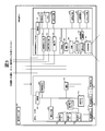
- FIG. 3 is a block diagram showing an example of a specific circuit configuration of the above-described illumination device 10 with a video projection function.
- the illumination device with a video projection function 10 includes a projection type video display unit 100 (small projector 30 in FIG. 2) having a video projection function and a lighting unit 200 having an illumination light irradiation function.
- An operation signal input unit 301 is an operation button or a light receiving unit of a remote controller, and inputs an operation signal from a user.
- the projection optical system 101 is an optical system that projects an image onto an upper surface (display surface or projection surface) 61, and includes at least one of a lens and a mirror.
- the display element 102 is an element that generates an image by modulating transmitted light or reflected light.
- a transmissive liquid crystal panel, a reflective liquid crystal panel, a DMD (Digital Micromirror Device: registered trademark) panel, or the like is used.
- the display element driving unit 103 sends a drive signal corresponding to the video signal to the display element 102.
- the light source 105 generates light for image projection, and uses a high-pressure mercury lamp, a xenon lamp, an LED light source, a laser light source, or the like.
- the power source 106 converts an AC current input from the outside into a DC current and supplies power to the light source 105. Further, the power supply 106 supplies necessary DC currents to the other components.
- the illumination optical system 104 condenses the light generated by the light source 105, makes it more uniform, and irradiates the display element 102 with it.
- the cooling unit 115 cools each part, such as the light source 105, the power source 106, or the display element 102, which is in a high temperature state, by air cooling or liquid cooling as necessary.
- the operation input unit 107 is an operation button or a light receiving unit of a remote controller, and inputs an operation signal from the user.
- the operation input unit 107 may receive an infrared signal or a radio signal from the operation panel 70 of FIG.
- the operation input unit 107 may be omitted.
- the video signal input unit 131 connects an external video output device and inputs video data.
- the audio signal input unit 133 inputs an audio data by connecting an external audio output device.
- the audio output unit 140 can perform audio output based on the audio data input to the audio signal input unit 133. Further, the audio output unit 140 may output a built-in operation sound or an error warning sound.
- the communication unit 132 is connected to an external information processing apparatus and inputs / outputs various control signals.
- the communication unit 132 may perform wired communication or wireless communication with the operation panel 70 of FIG.
- the nonvolatile memory 108 stores various data used for the projector function.
- the memory 109 stores video data to be projected and control data for the apparatus.
- the control unit 110 controls the operation of each connected unit.
- the image adjustment unit 160 performs image processing on the video data input by the video signal input unit 131.
- Examples of the image processing include scaling processing for enlarging, reducing, and deforming the image, bright adjustment processing for changing the brightness, contrast adjustment processing for changing the contrast curve of the image, and components obtained by decomposing the image into light components. Retinex processing for changing the weighting for each.
- the storage unit 170 records video, images, audio, various data, and the like.
- video, image, audio, various data, etc. may be recorded in advance at the time of product shipment, and video, image, audio, various data, etc. acquired from an external device, an external server, etc. via the communication unit 132 may be used. It may be recorded.
- Video, images, various data, and the like recorded in the storage unit 170 may be output as projection video via the display element 102 and the projection optical system 101.
- the sound recorded in the storage unit 170 may be output as sound from the sound output unit 140.
- the projection type image display unit 100 can be provided with various functions.
- the projection display unit 100 does not necessarily have all the above-described configurations. Any configuration may be used as long as it has a function of projecting an image.
- the control unit 201 controls each unit to be connected.
- the operation input unit 203 is an operation button or a light receiving unit of a remote controller, and inputs an operation signal from the user.
- the operation input unit 203 may receive an infrared signal or a radio signal from the operation panel 70 of FIG.
- the operation input unit 203 may be omitted.
- the nonvolatile memory 204 stores various data used in the lighting unit 200.
- the power source 202 converts an AC current input from the outside into a DC current and supplies power to the light emitting element drivers (210, 220, etc.). Further, the power source 202 supplies necessary DC currents to the other units.
- the light emitting element drivers (210, 220, etc.) emit light from the light emitting elements (211, 212, 213, 221, 222, 223, etc.) based on the control of the control unit 201 using the power supplied from the power source 202.
- the light emitting element serves as a light source of illumination light emitted from the illumination unit 200.
- the light emitting element driver A210 collectively drives n light emitting elements A1, A2,... An (211, 212, 213, etc.) connected in series.
- the light emitting element driver A 210 changes the luminance, color, and the like of these light emitting elements based on the control of the control unit 201.
- the light emitting element driver B220 collectively drives m light emitting elements B1, B2,... Bm (221, 222, 223, etc.) connected in series.
- the light emitting element driver B220 changes the luminance and color of these light emitting elements based on the control of the control unit 201.
- FIG. 3 two examples of a light emitting element driver and a set of a plurality of light emitting elements are shown, but one or three or more sets may be used. What is necessary is just to increase / decrease as needed.
- the illumination unit 200 can emit illumination light with variable brightness or color.
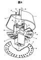
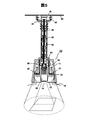
- Example 1 Since the outline of the internal configuration of the first embodiment is the same as that of FIG. 2, the description thereof is omitted here, and the cooling mechanism that is a feature thereof will be described below with reference to FIG.
- the disk-shaped substrate 21 constituting the above-described illumination light source 20 is formed by forming a metal such as aluminum or copper having excellent thermal conductivity into a cylindrical shape.
- the semiconductor light-emitting element 22 formed of a plurality of LEDs described above is attached to the lower surface side of the figure.
- the bottom wall (the wall on the upper surface side of the figure) of the metal container 23 also includes an opening (center part of the figure) through which the wiring from the above-described lighting appliance outlet 51 (see FIG. 2) passes.
- a plurality of openings 24 are formed.
- the above-described outer box-type small projector 30 is housed with the projection lens 31 facing downward, and is fixed at a predetermined position by a fixing member such as a screw 25, for example. It is fixed.
- a power supply unit 80 that supplies required power to the illumination light source 20 and the small projector 30 is also fixed at a predetermined position inside the metal container 23 by a fixing member such as a screw 25.
- a plurality of rod-shaped members 26 are integrally formed on the upper surface wall of the metal container 23, and as is apparent from the drawing, the tips of these rod-shaped members 26 have a conical main body (shade) 11. Is also fixed to a predetermined position by a fixing member such as a screw 25.
- the outer cone-shaped main body (shade) 11 is fixed to the lower end of a holder 40 made of a cylindrical pipe made of a metal such as aluminum having excellent thermal conductivity.
- the illumination light source 20 in order to diffuse the illumination light from the illumination light source 20 and uniformly irradiate it downward, it is attached so as to cover the lower opening of the main body 11 and is attached to the diffuser plate 12 from the small projector 30 at its center.
- a plurality of small-diameter openings (small-diameter openings) 15 are formed in the periphery thereof.
- the ambient air heated by the exhaust heat of the light source flowing out from the exhaust port 35 of the small projector 30 and the heat generated from the power supply unit 80 is indicated by a bold line in the figure.
- the pipe rises. Thereafter, it flows out through the upper part of the holder 40 that is the pipe and the vent opening 43 formed in the outlet cover 41.
- the external air is the opening 15 or the opening 14 which is a small diameter opening formed in the diffusion plate 12.
- the main body (shade) 11 flows into the main body (shade) 11 through a gap between the bowl-shaped portion 21 which is a disc-shaped substrate and the main body (shade) 11, and part of the main body (shade) 11 passes through the small projector 30. Move to top of (shade) 11.
- the air inside the main body (shade) 11 can be efficiently replaced (circulated) with the external air by the convection due to the chimney effect by the cylindrical pipe 40. That is, the opening 15 and the opening 14 which are small-diameter openings serve as intake openings into the main body (shade) 11.
- heat generated from the heat generating part (in this example, mainly the light source 20 for illumination, the small projector 30, and the power supply part 80) housed inside the main body (shade) 11 is By transmitting to the air flow circulating inside, it is possible to efficiently discharge to the outside and cool the heat generating portion.
- the light outlet of the light source of the small projector 30 serving as a heat generation source is positioned lower than the lower flow path opening 44 of the holder 40 in the vertical direction.
- 35 and an illumination light source 20 serving as a heat generation source and further, an opening 14 serving as an air inlet to the space formed by the main body 11 and the diffusion plate 12 at a position lower in the vertical direction than these heat generation sources It is desirable to arrange the opening 15.
- the opening 15 that is a small-diameter opening is provided in the diffusion plate 12, but it is not necessarily provided in the diffusion plate 12. You may provide in the side surface of the main body 11.
- the opening shape of the opening 15, which is a small-diameter opening is a small diameter, but it may be an elongated slit shape.
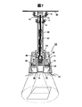
- FIG. 5 shows an outline of the internal configuration of the second embodiment. Since the schematic configuration is the same as that of FIG. 2, the description thereof is omitted here, and the cooling mechanism that is a feature thereof is described below. This will be described with reference to FIG.
- the above-described metal container 23 is extended upward and formed integrally with the lower end of the holder 40, which is a cylindrical pipe made of metal such as aluminum. Is.
- the light source 20 for illumination it is set as the disk-shaped board
- substrate 21 which comprises the light source for illumination by forming the bowl-shaped part in the lower end of the metal container 23, and arrange
- a disk-shaped member 26 is fixed and attached to the substantially central portion of the metal container 23, and the small projector 30 and the power supply unit 80 housed in the internal space of the metal container 23 by the member 26. Is fixed at a predetermined position by a fixing member such as a screw 25. Furthermore, a plurality of elongated slit-shaped openings 27 are provided in the upper part of the metal container 23 (above the member 26), whereby the interior space of the main body (shade) 11 and the interior of the metal container 23 are provided. Air permeability between the space is secured. The main body (shade) 11 is held at a predetermined position by a protrusion 28 formed on the upper portion of the metal container 23.
- the diffusion plate 12 is the same as described above in order to diffuse the illumination light from the illumination light source 20 attached so as to cover the lower opening of the main body 11 and uniformly irradiate it downward.
- the surrounding air heated by the exhaust heat of the light source flowing out from the exhaust port 35 of the small projector 30 and the heat generation of the power supply unit 80 is indicated by a bold line in the figure. As shown by the arrow, it rises in the internal space of the metal container 23. Further, the air heated by the bowl-shaped portion 21 which is a disk-shaped substrate of the illumination light source 20 moves upward from there, and passes through a plurality of slit-shaped openings 27 formed in the upper portion of the metal container 23. It flows into the internal space of the metal container 23 of FIG.
- the opening 15 and the opening 14 which are small-diameter openings serve as intake openings into the main body (shade) 11.
- the heat generated from the semiconductor light emitting element 22 of the illumination light source 20 is generated from the bowl-shaped portion of the metal container 23 that is a disk-shaped substrate. 6 is transmitted through the wall surface of the metal container 23 in FIG. 6 to the holder 40 which is a metal cylindrical pipe excellent in thermal conductivity formed integrally therewith. Similarly, the heat generated from the small projector 30 and the power supply unit 80 is also applied to the wall surface of the metal container 23 and the metal through the disk-shaped member 26 of FIG. It is transmitted to the holder 40 which is a cylindrical pipe made of metal.
- the heat generation is directed to the metal metal container 23 having excellent thermal conductivity and the holder 40 which is a cylindrical pipe. Therefore, it is possible to more efficiently realize the cooling of the heat generating portion.
- a small projector serving as a heat generation source at a position lower than the lower flow path opening 44 of the holder 40 in the vertical direction.
- 30 light source exhaust ports 35 and an illumination light source 20 serving as a heat generation source are arranged, and an air inflow port to a space formed by the main body 11 and the diffusion plate 12 at a position lower in the vertical direction than these heat generation sources. It is desirable to arrange the opening 14 and the opening 15.
- the opening 15 that is a small-diameter opening is provided in the diffusion plate 12, but it is not always necessary to provide the diffusion plate 12. You may provide in the side surface of the main body 11.
- the opening shape of the opening 15 that is a small-diameter opening is a small diameter, but may be a long and narrow slit shape.
- the diameter (A: cross-sectional area [m 2 ] of the chimney) and the length (h: the height of the chimney) which are metal cylindrical pipes. It is important to set [m]) appropriately.
- the diameter of the holder 40, which is a cylindrical pipe will need to be set in consideration of the wiring 42 from the outlet for the lighting fixture housed therein.
- a fan for performing forced ventilation is further employed.
- the configuration is shown.
- the holder in addition to the configuration shown in the first embodiment (or the configuration of the second embodiment), the holder is a metal cylindrical pipe.
- a small ventilation fan 45 is attached to a part (upper part) of 40 and the opening 43 of the hemispherical outlet cover 41.
- the ventilation fan 45 may be attached to one of the part (upper part) 46 of the holder 40 or the opening 43 of the outlet cover 41.
- the ventilation fan 45 by attaching the ventilation fan 45, the circulating air flow rate is increased, so that the heat generating portion can be cooled more efficiently.
- the ventilation fan 45 is preferably attached at a position close to the ceiling surface 50, such as the upper part of the holder 40, which is a cylindrical pipe as described above, and the hemispherical outlet cover 41. This is because the accompanying ventilation fan 45 is arranged at a position further away from the user to obtain an effect of reducing the adverse effects of noise (silent effect).
- these ventilation fans 45 may be provided inside the main body (shade) 11 and turned on / off using a temperature detected by a temperature sensor, or the operation panel 70 is used. Then, the operator may control it.
- the present invention is not limited to the above-described embodiments, and includes various modifications.
- the above-described embodiments are described in detail for the entire system in order to explain the present invention in an easy-to-understand manner, and are not necessarily limited to those having all the configurations described.
- a part of the configuration of one embodiment can be replaced with the configuration of another embodiment, and the configuration of another embodiment can be added to the configuration of one embodiment.
- SYMBOLS 10 Illuminating device, 11 ... Main body (shade) (shade), 12 ... Diffusing plate, 14, 15 ... Opening part, 20 ... Light source for illumination, 23 ... Metal container, 30 ... Small projector, 32 ... Projection lens, 40 ... Holder, 41 ... outlet cover, 43 ... opening, 44 ... lower flow path opening, 45 ... cooling fan
Landscapes
- Engineering & Computer Science (AREA)
- General Engineering & Computer Science (AREA)
- Arrangement Of Elements, Cooling, Sealing, Or The Like Of Lighting Devices (AREA)
- Projection Apparatus (AREA)
Abstract
La présente invention concerne un dispositif d'éclairage ayant une excellente fonction de projection d'image, capable de dissiper efficacement, vers l'extérieur, la chaleur générée par un élément d'émission de lumière et un projecteur. Ce dispositif d'éclairage est maintenu dans un état suspendu à un support fixé à une surface de plafond, et émet une lumière d'éclairage. Le dispositif d'éclairage est doté : d'une source de lumière pour générer de la lumière d'éclairage, ladite source de lumière étant disposée dans le boîtier ; d'une plaque de diffusion, qui est fixée à une partie du boîtier et qui diffuse la lumière d'éclairage émise par la source de lumière ; et d'un projecteur, qui est disposé à l'intérieur d'un espace formé par le boîtier et une partie de la plaque de diffusion, et qui projette une image sur une surface de projection. Le support est formé de telle sorte que son intérieur soit creux, et le boîtier est configuré de manière à guider, vers la section creuse du support, l'air chauffé par la source de lumière et le projecteur, qui sont placés à l'intérieur du boîtier.
Priority Applications (1)
| Application Number | Priority Date | Filing Date | Title |
|---|---|---|---|
| PCT/JP2015/060709 WO2016162913A1 (fr) | 2015-04-06 | 2015-04-06 | Dispositif d'éclairage |
Applications Claiming Priority (1)
| Application Number | Priority Date | Filing Date | Title |
|---|---|---|---|
| PCT/JP2015/060709 WO2016162913A1 (fr) | 2015-04-06 | 2015-04-06 | Dispositif d'éclairage |
Publications (1)
| Publication Number | Publication Date |
|---|---|
| WO2016162913A1 true WO2016162913A1 (fr) | 2016-10-13 |
Family
ID=57071879
Family Applications (1)
| Application Number | Title | Priority Date | Filing Date |
|---|---|---|---|
| PCT/JP2015/060709 Ceased WO2016162913A1 (fr) | 2015-04-06 | 2015-04-06 | Dispositif d'éclairage |
Country Status (1)
| Country | Link |
|---|---|
| WO (1) | WO2016162913A1 (fr) |
Cited By (1)
| Publication number | Priority date | Publication date | Assignee | Title |
|---|---|---|---|---|
| WO2019194173A1 (fr) * | 2018-04-03 | 2019-10-10 | 国立大学法人京都大学 | Structure de support de projecteur médical |
Citations (5)
| Publication number | Priority date | Publication date | Assignee | Title |
|---|---|---|---|---|
| JPH11144510A (ja) * | 1997-11-06 | 1999-05-28 | Matsushita Electric Ind Co Ltd | 照明装置 |
| JP2006127845A (ja) * | 2004-10-27 | 2006-05-18 | Nec Lighting Ltd | 照明器具 |
| JP2012186118A (ja) * | 2011-03-08 | 2012-09-27 | Toshiba Lighting & Technology Corp | 照明器具 |
| JP2014067634A (ja) * | 2012-09-26 | 2014-04-17 | Gs Yuasa Corp | 照明装置 |
| JP2014170675A (ja) * | 2013-03-04 | 2014-09-18 | Panasonic Corp | 照明装置 |
-
2015
- 2015-04-06 WO PCT/JP2015/060709 patent/WO2016162913A1/fr not_active Ceased
Patent Citations (5)
| Publication number | Priority date | Publication date | Assignee | Title |
|---|---|---|---|---|
| JPH11144510A (ja) * | 1997-11-06 | 1999-05-28 | Matsushita Electric Ind Co Ltd | 照明装置 |
| JP2006127845A (ja) * | 2004-10-27 | 2006-05-18 | Nec Lighting Ltd | 照明器具 |
| JP2012186118A (ja) * | 2011-03-08 | 2012-09-27 | Toshiba Lighting & Technology Corp | 照明器具 |
| JP2014067634A (ja) * | 2012-09-26 | 2014-04-17 | Gs Yuasa Corp | 照明装置 |
| JP2014170675A (ja) * | 2013-03-04 | 2014-09-18 | Panasonic Corp | 照明装置 |
Cited By (1)
| Publication number | Priority date | Publication date | Assignee | Title |
|---|---|---|---|---|
| WO2019194173A1 (fr) * | 2018-04-03 | 2019-10-10 | 国立大学法人京都大学 | Structure de support de projecteur médical |
Similar Documents
| Publication | Publication Date | Title |
|---|---|---|
| JP6594521B2 (ja) | 照明装置 | |
| KR100683171B1 (ko) | 방열장치 및 그것을 구비하는 프로젝터 | |
| JP6429257B2 (ja) | 照明装置 | |
| JP7113245B2 (ja) | 制御装置、点灯装置及び照明システム | |
| JP6557354B2 (ja) | 照明装置 | |
| JPWO2018158885A1 (ja) | 照明装置 | |
| US10415776B2 (en) | Illumination apparatus | |
| JP6334001B2 (ja) | 照明装置 | |
| JP2016126114A (ja) | 投影装置及び照明装置 | |
| JP7001994B2 (ja) | 制御装置、照明装置及び照明システム | |
| JP6745051B2 (ja) | 画像投写装置 | |
| WO2016162913A1 (fr) | Dispositif d'éclairage | |
| JP6291906B2 (ja) | 光源用ハウジング、光源装置、画像投射装置 | |
| JP6321148B2 (ja) | 投写型映像表示装置 | |
| CN109073168B (zh) | 照明装置 | |
| JP2018028965A (ja) | 照明装置 | |
| WO2016060086A1 (fr) | Dispositif d'éclairage |
Legal Events
| Date | Code | Title | Description |
|---|---|---|---|
| 121 | Ep: the epo has been informed by wipo that ep was designated in this application |
Ref document number: 15888408 Country of ref document: EP Kind code of ref document: A1 |
|
| NENP | Non-entry into the national phase |
Ref country code: DE |
|
| 122 | Ep: pct application non-entry in european phase |
Ref document number: 15888408 Country of ref document: EP Kind code of ref document: A1 |
|
| NENP | Non-entry into the national phase |
Ref country code: JP |