WO2016162985A1 - Ciseaux pour coiffure - Google Patents
Ciseaux pour coiffure Download PDFInfo
- Publication number
- WO2016162985A1 WO2016162985A1 PCT/JP2015/061026 JP2015061026W WO2016162985A1 WO 2016162985 A1 WO2016162985 A1 WO 2016162985A1 JP 2015061026 W JP2015061026 W JP 2015061026W WO 2016162985 A1 WO2016162985 A1 WO 2016162985A1
- Authority
- WO
- WIPO (PCT)
- Prior art keywords
- ring
- finger
- half body
- rotation
- blade
- Prior art date
- Legal status (The legal status is an assumption and is not a legal conclusion. Google has not performed a legal analysis and makes no representation as to the accuracy of the status listed.)
- Ceased
Links
Images




Classifications
-
- B—PERFORMING OPERATIONS; TRANSPORTING
- B26—HAND CUTTING TOOLS; CUTTING; SEVERING
- B26B—HAND-HELD CUTTING TOOLS NOT OTHERWISE PROVIDED FOR
- B26B13/00—Hand shears; Scissors
- B26B13/12—Hand shears; Scissors characterised by the shape of the handles
- B26B13/20—Hand shears; Scissors characterised by the shape of the handles with gripping bows in the handle
-
- B—PERFORMING OPERATIONS; TRANSPORTING
- B25—HAND TOOLS; PORTABLE POWER-DRIVEN TOOLS; MANIPULATORS
- B25G—HANDLES FOR HAND IMPLEMENTS
- B25G1/00—Handle constructions
- B25G1/10—Handle constructions characterised by material or shape
- B25G1/102—Handle constructions characterised by material or shape the shape being specially adapted to facilitate handling or improve grip
Definitions
- the present invention relates to a barber or beauty salon.
- a first rod half having a moving blade and a thumb ring and a second rod half having a stationary blade portion, a ring finger ring, and a little finger hook portion are rotatably connected by a shaft support portion.
- the thumb is inserted into the thumb ring
- the ring finger is inserted into the ring ring
- the index finger and the middle finger are attached to the handle portion of the second heel half
- the little finger is hung on the little finger hook.
- the moving blade rotates with respect to the stationary blade, and the hair between the stationary blade and the moving blade is cut.
- the contact between the ring finger and the ring ring will hold the posture of the heel.
- a load is applied to the ring contact portion of the ring finger. If you use a spear for many years, the ring finger may octopus or deform. That is, a burden is imposed on the cutting engineer without knowing it.
- one of the occupational diseases of barbers and hairdressers is finger and wrist tendonitis.
- the load on the ring finger may cause finger tendonitis.
- the load may be transmitted from the finger to the wrist, which may cause distraction of wrist tendonitis.
- the thumb ring and ring finger ring collide.
- the impact of this collision can be the cause of tendonitis of the fingers and wrists.
- Patent Document 1 In order to prevent tendonitis, for example, the prior art described in Patent Document 1 has been proposed. That is, a hollow portion is formed in at least a part of the handle portion of the heel, and a viscoelastic body is enclosed in the hollow portion. Part of the impact when closing the heel can be mitigated by the excellent shock-absorbing and vibration-absorbing power of the viscoelastic body.
- Patent Document 1 cannot reduce the load on the ring finger.
- This invention solves the said subject, and it aims at providing the bag which can reduce the burden to a cutting engineer by reducing the load to a ring finger.
- the inventor of the present application examined in detail the cause of the load on the ring finger.
- the ring finger is inserted into the ring finger ring, and the thumb abdomen is pressed against the thumb ring, the moving blade rotates relative to the stationary blade, Cut the hair in between.
- the contact between the ring finger and the ring finger ring holds the posture of the heel (especially a stationary blade).
- the trajectory formed by the thumb ring and ring finger ring when opening and closing the heel is constant.
- the cutting engineer adjusts the movement of the finger so as to match the trajectories of the two rings. As a result, a large load is generated at the ring contact portion of the ring finger.
- the inventors of the present application have arrived at the present invention as a result of paying attention to the above cause and intensively studying countermeasures.
- a first rod half having a blade portion and a thumb ring and a second rod half having a blade portion and a ring finger ring are rotatably connected by a shaft support portion. It is a spear.
- the second hook half body is formed by connecting a second hook half blade side part and a second hook half ring side part via a connecting part.
- the second half half blade side part and the second half half ring side part are coupled so as to be rotatable about a coupling axis.
- the connecting portion is provided with an elastic mechanism for returning the rotation.
- Rotating the side of the second rod half ring can reduce the load on the ring finger and the impact when the heel closes. Also, when the heel is closed, the four fingers are allowed to bend while maintaining the posture of the stationary blade.
- Rotation against the intention can be suppressed by the reaction force by the elastic mechanism acting against the rotation. Also, when the heel closes, the reaction force acts as an urging force.
- the elastic mechanism has a torsion spring.
- the second scissors half blade side part rotates in the direction of rotation of four fingers with respect to the second scissors half ring side part.
- the connecting portion is provided with a rotation restricting mechanism that restricts the rotation when the connecting portion rotates by a predetermined angle.
- connection portion is provided with a connection holding mechanism for holding the connection in a rotatable state.
- a finger hooking portion for hooking an index finger or / and a middle finger is provided on the tip side of the ring finger from the ring finger ring of the second rod half ring side portion.
- the first hook half or the second hook half is a handle portion, and a hit point is provided closer to the shaft support portion than the connecting portion.
- a first rod half having a blade portion and a thumb ring and a second rod half having a blade portion and a ring finger ring are rotatably connected by a shaft support portion. It is a spear.
- a connecting portion that connects the second rod half body blade side portion and the second rod half body ring side portion so as to integrate the second rod half body;
- the load on the ring finger can be reduced.
- the burden on the cutting engineer can be reduced.
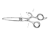
- the moving blade 11 is continuous with the thumb ring 13 through the handle portion 12 and constitutes the heel half 1.
- the stationary blade 21 is continuous with the ring finger ring 23 via the handle portion 22 and constitutes the heel half body 2.
- a little finger hook 24 is extended to the ring finger ring 23.
- the heel half 1 and the heel half 2 are rotatably connected to each other by a shaft support portion 3. By pressing the thumb belly side against the thumb ring 13, the moving blade 11 rotates with respect to the stationary blade 21 and cuts the hair between the stationary blade 21 and the moving blade 11.
- the above is the basic configuration of the kite.
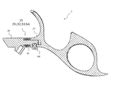
- the connecting portion 25 is provided in the handle portion 22. That is, the heel half 2 is formed by connecting the heel half blade side portion 26 and the heel half ring side portion 27 via the connecting portion 25.
- the central axis of the handle 22 is a connecting axis.
- connection unit 25 includes a rotation mechanism 51, an elastic mechanism 52, a rotation restraint mechanism 53, and a connection holding mechanism 54.
- the half ring side 27 is rotatable about the connecting shaft with respect to the half blade side 26.
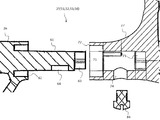
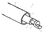
- a shaft portion 61 having a smaller diameter than the handle portion 22 extends from the end portion of the saddle blade side portion 26.
- a groove is provided at the base of the shaft portion 61 so as to surround the shaft portion 61 to form a torsion spring insertion portion 62.
- a fan-shaped member is provided on the end surface of the shaft portion 61 to form a rotation restricting portion 63.
- Grooves are provided in the circumferential direction on the peripheral surface of the shaft portion 61 to form a connection holding groove 64.
- a hole corresponding to the shaft portion 61 is provided at the end of the half ring side portion 27 to form a bearing portion 71.
- the diameter is increased by one turn from the shaft hole, and a torsion spring insertion portion 72 is formed.
- Rotating range portion 73 is provided in the depth of bearing portion 71.
- a screw hole 74 that communicates from the surface to the bearing portion 71 is provided in the saddle half ring side portion 27.
- the rotation mechanism 51 will be described.
- the shaft portion 61 is inserted into the bearing portion 71, and the rotation mechanism 51 is formed. That is, the saddle half ring side portion 27 can be rotated around the connecting shaft with respect to the saddle half blade side portion 26.
- the elastic mechanism 52 will be described.
- the torsion spring insertion part 62 and the torsion spring insertion part 72 are in positions facing each other and form a space.
- a torsion spring 82 is inserted between the shaft 61 and the torsion spring insertion portions 62 and 72 to form the elastic mechanism 52.
- the elastic mechanism 52 acts to return the rotation to the rotation by the rotation mechanism 51 (details will be described later).
- the rotation restraint mechanism 53 will be described.
- the rotation restricting portion 63 and the rotatable range portion 73 correspond to each other.
- the fan-shaped member that is the rotation restricting portion 63 has a first locking surface and a second locking surface.
- the rotatable range portion 73 is a fan-shaped space having an angle larger than the fan angle of the rotation restricting portion 63 and has a first locking surface and a second locking surface.
- the rotation by the rotation mechanism 51 is the rotation in the rotation direction of the finger by engaging the first locking surface of the rotation restricting portion 63 and the first locking surface of the rotatable range portion 73.
- the rotation in the reverse direction is restricted.
- the rotation by the rotation mechanism 51 is a predetermined angle (less than 45 to 90 degrees, for example, 70 Degree).
- connection holding mechanism 54 will be described.
- the connection holding groove 64 and the screw hole 74 correspond to each other.
- the connection holding screw 84 is screwed into the screw hole 74, the tip of the connection holding screw 84 is positioned in the connection holding groove 64.
- the distal end of the connection holding screw 84 engages with the connection holding groove 64, the axial movement is restricted, and the connected state is maintained.
- connection holding screw 84 moves along the connection holding groove 64 as the rotation mechanism 51 rotates. Therefore, the connection holding mechanism 54 does not hinder the rotation.
- Finger hooks 41 and 42 are provided on the handle 22 of the heel half ring side 27.
- the finger latch 41 is a quarter ring 41
- the quarter ring 41 extends from between the shaft support 3 and the ring finger ring 23 toward the tip of the heel and comes into contact with the index finger back.
- the quarter ring 41 has a quarter arc shape of the oval ring finger ring 23. As a result, the tip end side of the quarter ring 41 is opened.
- the one-ace ring 42 extends from the ring finger ring 23 toward the tip of the heel and comes into contact with the back part of the middle finger.
- the one-ace ring 42 has a shape approximating the 1/8 arc shape of the elliptical ring finger ring 23. As a result, the leading end side of the one-ace ring 42 is opened.
- a hit point 29 is provided between the connecting portion 25 and the shaft support portion 3 in the handle portion 22 of the saddle blade side portion 26.
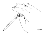
- FIG. 6 is a schematic diagram of a prior art cocoon
- FIG. 7 is a diagram for explaining a haircut operation of the prior art.
- the moving blade rotates with respect to the static blade, and the eyelid opens. Further, by pressing the belly side of the thumb against the thumb ring, the moving blade rotates in the opposite direction with respect to the stationary blade, and the heel closes. At that time, the hair between the stationary blade and the moving blade is cut. This opening and closing is repeated.
- the posture of the stationary blade is maintained by the contact between the ring finger and the ring finger ring.
- Four fingers index finger, middle finger, ring finger, little finger
- Maintaining this posture is contrary to the original human movement and muscles other than the fingers are tense.
- the ring finger is restrained by the ring ring, and a large load is generated at the ring contact portion of the ring finger.
- the above operations may put a burden on the cutting engineer and may cause tendonitis.
- FIG. 8 and 9 are diagrams for explaining the haircut operation of this embodiment.
- FIG. 10 is a diagram for explaining the operation details of this embodiment.
- the thumb is inserted into the thumb ring 13, the back of the index finger is brought into contact with the quarter ring 41, the middle finger is brought into contact with the one-ace ring 42, the ring finger is inserted into the ring finger ring 23, and the little finger is put on the little finger hook 24.
- the counteracting force of the torsion spring 82 acts to suppress the rotation contrary to the intention of the cutting engineer.
- the cutting engineer obtains a sense of unity in which the scissors stick to the finger.
- the movement of the finger is matched to the trajectories of the two rings, whereas in the present embodiment, the above rotation matches the movement of the finger.
- the ring finger is not restrained by the ring finger ring, and the load on the ring finger is greatly reduced.
- the counter force of the torsion spring 82 acts as a biasing force.
- the force to move the thumb in the opening direction can be reduced.
- the load on the ring finger can be reduced and the burden on the cutting engineer can be reduced. As a result, the tendonitis of fingers and wrists can be prevented.
- This embodiment includes a rotation restraining mechanism 53. Thereby, reverse rotation and excessive rotation can be suppressed.
- This embodiment includes a connection holding mechanism 54. Thereby, while making the said rotation possible, the integrity as the saddle half 2 is maintainable.
- the present embodiment includes a quarter ring 41 and a one-ace ring 42.
- This embodiment includes hit points 29.
- the rotation absorbs the impact as described above, it is not necessary to provide a hit point between the thumb ring and the ring finger ring.
- the hit point 29 is provided in the heel half blade side part 26, rotation of the heel half ring side part 27 is not inhibited. Therefore, the cutting engineer does not feel uncomfortable.
- FIG. 11 shows a modification of the present invention.
- a connecting portion 25, a turning mechanism 51, and an elastic mechanism 52 are added to a conventional bag (see FIG. 6).
- the load on the ring finger can be reduced and the burden on the cutting engineer can be reduced. As a result, the tendonitis of fingers and wrists can be prevented.
- the shaft portion 61 and the bearing portion 71 are used as the rotation mechanism 51, but other configurations may be used.
- a bearing portion may be provided on the heel half blade side portion 26 and a shaft portion may be provided on the heel half ring side portion 27 (see FIG. 12).
- the torsion spring 82 is used as the elastic mechanism 52, but other configurations may be used.
- an elastic body such as a spring, leaf spring, fluid spring, or resin may be used.
- the locking structure of the rotation restricting portion 63 and the rotatable range portion 73 is used as the rotation restricting mechanism 53, but other configurations may be used.
- a bearing part is provided on the saddle half blade side part 26, a shaft part is provided on the collar half ring side part 27, a rotation restricting part is provided at the base part of the shaft part, and a rotatable range part is provided on the bearing part. (See FIG. 12).
- connection holding groove 64, the screw hole 74, and the connection holding screw 84 are used as the connection holding mechanism 54, but other configurations may be used as long as the connection can be held while ensuring the rotation.
- the quarter ring 41 and the one-ace ring 42 are used as the finger hooking portions, but either one may be used.
- the hit point 29 is provided on the handle portion 22 of the heel blade side portion 26, but it may be a corresponding position on the handle portion 12.
Landscapes
- Engineering & Computer Science (AREA)
- Mechanical Engineering (AREA)
- Life Sciences & Earth Sciences (AREA)
- Forests & Forestry (AREA)
- Scissors And Nippers (AREA)
Abstract
Priority Applications (5)
| Application Number | Priority Date | Filing Date | Title |
|---|---|---|---|
| PCT/JP2015/061026 WO2016162985A1 (fr) | 2015-04-08 | 2015-04-08 | Ciseaux pour coiffure |
| CN201580078267.5A CN107405776A (zh) | 2015-04-08 | 2015-04-08 | 理发美发剪刀 |
| KR1020177027293A KR101822020B1 (ko) | 2015-04-08 | 2015-04-08 | 이미용용 가위 |
| JP2015557674A JP5943498B1 (ja) | 2015-04-08 | 2015-04-08 | 理美容用鋏 |
| US15/562,404 US20180141222A1 (en) | 2015-04-08 | 2015-04-08 | Scissors for hairdressing |
Applications Claiming Priority (1)
| Application Number | Priority Date | Filing Date | Title |
|---|---|---|---|
| PCT/JP2015/061026 WO2016162985A1 (fr) | 2015-04-08 | 2015-04-08 | Ciseaux pour coiffure |
Publications (1)
| Publication Number | Publication Date |
|---|---|
| WO2016162985A1 true WO2016162985A1 (fr) | 2016-10-13 |
Family
ID=56289090
Family Applications (1)
| Application Number | Title | Priority Date | Filing Date |
|---|---|---|---|
| PCT/JP2015/061026 Ceased WO2016162985A1 (fr) | 2015-04-08 | 2015-04-08 | Ciseaux pour coiffure |
Country Status (5)
| Country | Link |
|---|---|
| US (1) | US20180141222A1 (fr) |
| JP (1) | JP5943498B1 (fr) |
| KR (1) | KR101822020B1 (fr) |
| CN (1) | CN107405776A (fr) |
| WO (1) | WO2016162985A1 (fr) |
Families Citing this family (6)
| Publication number | Priority date | Publication date | Assignee | Title |
|---|---|---|---|---|
| USD899207S1 (en) * | 2018-02-28 | 2020-10-20 | Shark Fin Shear Co., Inc. | Scissors handle |
| USD908453S1 (en) * | 2019-02-14 | 2021-01-26 | Shark Fin Shear Co., Inc. | Scissors handle |
| US11865734B2 (en) * | 2021-08-04 | 2024-01-09 | Chao Wei | Slide cutting shears |
| KR102792384B1 (ko) | 2021-09-24 | 2025-04-08 | 인천대학교 산학협력단 | 이미용 가위용 그리퍼 및 이를 포함하는 이미용 가위 |
| IT202300014310A1 (it) | 2023-07-10 | 2025-01-10 | Cristian Nanni | Struttura di forbici da acconciatore |
| US12611787B1 (en) * | 2025-05-06 | 2026-04-28 | Randall B. Lowe | Scissors |
Citations (9)
| Publication number | Priority date | Publication date | Assignee | Title |
|---|---|---|---|---|
| JPS50143180A (fr) * | 1974-04-10 | 1975-11-18 | ||
| FR2627421A1 (fr) * | 1988-02-19 | 1989-08-25 | Taberlet Jean Jacques | Paire de ciseaux, notamment a usage de coupe de cheveux |
| JPH0626769U (ja) * | 1992-09-18 | 1994-04-12 | 株式会社東光舎 | はさみ |
| WO1997046353A1 (fr) * | 1996-06-04 | 1997-12-11 | Taberlet Jean Jacques | Outil a main tel qu'une paire de ciseaux a organe de prehension pivotant et rappel elastique |
| JP2004113539A (ja) * | 2002-09-27 | 2004-04-15 | Adachi Kogyo:Kk | 理美容鋏 |
| US20080172886A1 (en) * | 2007-01-19 | 2008-07-24 | Dong Ho Jun | Scissors with three axially pivoting and inter-changeable ringlets |
| US20120079724A1 (en) * | 2010-10-01 | 2012-04-05 | Tai-Wei Scissors Co., Ltd. | Adjustable finger loop structure for a scissors |
| US20130081282A1 (en) * | 2011-07-25 | 2013-04-04 | Shear Innovators, LLC | Ergonomic cutting shears |
| JP2014200570A (ja) * | 2013-04-09 | 2014-10-27 | 株式会社ヒカリ | 鋏 |
Family Cites Families (16)
| Publication number | Priority date | Publication date | Assignee | Title |
|---|---|---|---|---|
| US187713A (en) * | 1877-02-27 | Improvement in reversible scissors | ||
| US3825020A (en) * | 1972-01-19 | 1974-07-23 | T Myers | Method of cutting hair |
| BE814224A (fr) * | 1974-04-10 | 1974-08-16 | Ciseaux | |
| DE2811398C2 (de) * | 1978-03-16 | 1979-11-15 | Jaguar Stahlwaren Vertriebsgesellschaft Mbh & Co Kg, 5650 Solingen | Schere |
| US4642895A (en) * | 1985-11-04 | 1987-02-17 | Gauvry Glenn A | Scissors with adjustable thumb loop |
| JPH02189179A (ja) * | 1989-01-14 | 1990-07-25 | Hikari Hamono Kenkyusho:Kk | 理・美容用鋏 |
| FR2648384B1 (fr) * | 1989-06-14 | 1994-08-12 | Fernandes Patrick | Ciseaux, notamment pour coiffeurs |
| US5060381A (en) * | 1990-08-13 | 1991-10-29 | Taberlet Jean Jacques | Pair of scissors, in particular for use in the cutting of hair |
| CN2281250Y (zh) * | 1997-02-18 | 1998-05-13 | 张孟正 | 发剪 |
| US5781999A (en) * | 1997-03-07 | 1998-07-21 | Chang; Meng Cheng | Thinning scissors |
| FR2797606B1 (fr) * | 1999-08-16 | 2002-02-01 | Michel Droin | Paire de ciseaux ergonomique |
| GB2351254B (en) * | 2000-02-28 | 2001-10-03 | Wu Chin Sung | Shears |
| USD526880S1 (en) * | 2004-07-14 | 2006-08-22 | Randall Scott Ferman | Scissors handle |
| US20060064879A1 (en) * | 2004-09-30 | 2006-03-30 | Lauritzen Pamela S | Adjustable ergonomic scissors |
| CN202283728U (zh) * | 2011-09-23 | 2012-06-27 | 何庶民 | 一种美发剪刀 |
| TWM438365U (en) * | 2012-05-30 | 2012-10-01 | Meng-Zheng Zhang | Angle-adjustable multifunctional hair clippers |
-
2015
- 2015-04-08 WO PCT/JP2015/061026 patent/WO2016162985A1/fr not_active Ceased
- 2015-04-08 JP JP2015557674A patent/JP5943498B1/ja not_active Expired - Fee Related
- 2015-04-08 KR KR1020177027293A patent/KR101822020B1/ko not_active Expired - Fee Related
- 2015-04-08 US US15/562,404 patent/US20180141222A1/en not_active Abandoned
- 2015-04-08 CN CN201580078267.5A patent/CN107405776A/zh active Pending
Patent Citations (9)
| Publication number | Priority date | Publication date | Assignee | Title |
|---|---|---|---|---|
| JPS50143180A (fr) * | 1974-04-10 | 1975-11-18 | ||
| FR2627421A1 (fr) * | 1988-02-19 | 1989-08-25 | Taberlet Jean Jacques | Paire de ciseaux, notamment a usage de coupe de cheveux |
| JPH0626769U (ja) * | 1992-09-18 | 1994-04-12 | 株式会社東光舎 | はさみ |
| WO1997046353A1 (fr) * | 1996-06-04 | 1997-12-11 | Taberlet Jean Jacques | Outil a main tel qu'une paire de ciseaux a organe de prehension pivotant et rappel elastique |
| JP2004113539A (ja) * | 2002-09-27 | 2004-04-15 | Adachi Kogyo:Kk | 理美容鋏 |
| US20080172886A1 (en) * | 2007-01-19 | 2008-07-24 | Dong Ho Jun | Scissors with three axially pivoting and inter-changeable ringlets |
| US20120079724A1 (en) * | 2010-10-01 | 2012-04-05 | Tai-Wei Scissors Co., Ltd. | Adjustable finger loop structure for a scissors |
| US20130081282A1 (en) * | 2011-07-25 | 2013-04-04 | Shear Innovators, LLC | Ergonomic cutting shears |
| JP2014200570A (ja) * | 2013-04-09 | 2014-10-27 | 株式会社ヒカリ | 鋏 |
Also Published As
| Publication number | Publication date |
|---|---|
| KR20170115107A (ko) | 2017-10-16 |
| KR101822020B1 (ko) | 2018-01-25 |
| US20180141222A1 (en) | 2018-05-24 |
| JPWO2016162985A1 (ja) | 2017-04-27 |
| JP5943498B1 (ja) | 2016-07-05 |
| CN107405776A (zh) | 2017-11-28 |
Similar Documents
| Publication | Publication Date | Title |
|---|---|---|
| JP5943498B1 (ja) | 理美容用鋏 | |
| US7966733B2 (en) | Scissors with a ringlet | |
| US4642895A (en) | Scissors with adjustable thumb loop | |
| JP5872126B2 (ja) | 鋏 | |
| US11607208B2 (en) | Tissue securing device and method of use | |
| KR200445653Y1 (ko) | 이발용 안전가위 | |
| CN211243596U (zh) | 一种可转动调节的医用抓钳 | |
| CN221814422U (zh) | 一种方向可调式持针器 | |
| US20120089156A1 (en) | Apparatus and method for hair removal | |
| US20130220359A1 (en) | Comb | |
| JP2004528147A5 (fr) | ||
| AU2014271418A1 (en) | Improvements in, or related to, eye glass frames | |
| EP1358974A1 (fr) | Ciseaux | |
| JP3149935U (ja) | 安全な鋏 | |
| US20120010630A1 (en) | System and Method for Hair Removal | |
| JP2021153706A (ja) | アシスト力付与具、鋏、せん断具 | |
| US20250196380A1 (en) | Scissors | |
| JP7496672B2 (ja) | 前髪カット用ハサミ | |
| JP5778712B2 (ja) | 鋏 | |
| JP3114164U (ja) | 簡易式メガネ | |
| Kandali | Mirror Mirror on the Wall | |
| JP6582115B1 (ja) | 理美容鋏 | |
| KR20180124069A (ko) | 헤어 클립 | |
| JP2003205186A (ja) | 理容鋏 | |
| TW201238725A (en) | Scissors structure with functions of ring handle revolution and automatic reset |
Legal Events
| Date | Code | Title | Description |
|---|---|---|---|
| ENP | Entry into the national phase |
Ref document number: 2015557674 Country of ref document: JP Kind code of ref document: A |
|
| 121 | Ep: the epo has been informed by wipo that ep was designated in this application |
Ref document number: 15888478 Country of ref document: EP Kind code of ref document: A1 |
|
| ENP | Entry into the national phase |
Ref document number: 20177027293 Country of ref document: KR Kind code of ref document: A |
|
| WWE | Wipo information: entry into national phase |
Ref document number: 15562404 Country of ref document: US |
|
| NENP | Non-entry into the national phase |
Ref country code: DE |
|
| 122 | Ep: pct application non-entry in european phase |
Ref document number: 15888478 Country of ref document: EP Kind code of ref document: A1 |