WO2016163033A1 - 力覚センサおよびこれに用いる構造体 - Google Patents
力覚センサおよびこれに用いる構造体 Download PDFInfo
- Publication number
- WO2016163033A1 WO2016163033A1 PCT/JP2015/061300 JP2015061300W WO2016163033A1 WO 2016163033 A1 WO2016163033 A1 WO 2016163033A1 JP 2015061300 W JP2015061300 W JP 2015061300W WO 2016163033 A1 WO2016163033 A1 WO 2016163033A1
- Authority
- WO
- WIPO (PCT)
- Prior art keywords
- axis
- force
- graphic
- point
- pedestal
- Prior art date
- Legal status (The legal status is an assumption and is not a legal conclusion. Google has not performed a legal analysis and makes no representation as to the accuracy of the status listed.)
- Ceased
Links
Images









Classifications
-
- G—PHYSICS
- G01—MEASURING; TESTING
- G01L—MEASURING FORCE, STRESS, TORQUE, WORK, MECHANICAL POWER, MECHANICAL EFFICIENCY, OR FLUID PRESSURE
- G01L5/00—Apparatus for, or methods of, measuring force, work, mechanical power, or torque, specially adapted for specific purposes
- G01L5/16—Apparatus for, or methods of, measuring force, work, mechanical power, or torque, specially adapted for specific purposes for measuring several components of force
- G01L5/165—Apparatus for, or methods of, measuring force, work, mechanical power, or torque, specially adapted for specific purposes for measuring several components of force using variations in capacitance
-
- G—PHYSICS
- G01—MEASURING; TESTING
- G01L—MEASURING FORCE, STRESS, TORQUE, WORK, MECHANICAL POWER, MECHANICAL EFFICIENCY, OR FLUID PRESSURE
- G01L5/00—Apparatus for, or methods of, measuring force, work, mechanical power, or torque, specially adapted for specific purposes
- G01L5/16—Apparatus for, or methods of, measuring force, work, mechanical power, or torque, specially adapted for specific purposes for measuring several components of force
- G01L5/161—Apparatus for, or methods of, measuring force, work, mechanical power, or torque, specially adapted for specific purposes for measuring several components of force using variations in ohmic resistance
- G01L5/1627—Apparatus for, or methods of, measuring force, work, mechanical power, or torque, specially adapted for specific purposes for measuring several components of force using variations in ohmic resistance of strain gauges
-
- G—PHYSICS
- G01—MEASURING; TESTING
- G01L—MEASURING FORCE, STRESS, TORQUE, WORK, MECHANICAL POWER, MECHANICAL EFFICIENCY, OR FLUID PRESSURE
- G01L5/00—Apparatus for, or methods of, measuring force, work, mechanical power, or torque, specially adapted for specific purposes
- G01L5/22—Apparatus for, or methods of, measuring force, work, mechanical power, or torque, specially adapted for specific purposes for measuring the force applied to control members, e.g. control members of vehicles, triggers
- G01L5/223—Apparatus for, or methods of, measuring force, work, mechanical power, or torque, specially adapted for specific purposes for measuring the force applied to control members, e.g. control members of vehicles, triggers to joystick controls
-
- G—PHYSICS
- G01—MEASURING; TESTING
- G01L—MEASURING FORCE, STRESS, TORQUE, WORK, MECHANICAL POWER, MECHANICAL EFFICIENCY, OR FLUID PRESSURE
- G01L1/00—Measuring force or stress, in general
- G01L1/14—Measuring force or stress, in general by measuring variations in capacitance or inductance of electrical elements, e.g. by measuring variations of frequency of electrical oscillators
-
- G—PHYSICS
- G01—MEASURING; TESTING
- G01L—MEASURING FORCE, STRESS, TORQUE, WORK, MECHANICAL POWER, MECHANICAL EFFICIENCY, OR FLUID PRESSURE
- G01L1/00—Measuring force or stress, in general
- G01L1/14—Measuring force or stress, in general by measuring variations in capacitance or inductance of electrical elements, e.g. by measuring variations of frequency of electrical oscillators
- G01L1/142—Measuring force or stress, in general by measuring variations in capacitance or inductance of electrical elements, e.g. by measuring variations of frequency of electrical oscillators using capacitors
Definitions
- the present invention relates to a force sensor, and more particularly to a sensor suitable for detecting a force in a specific coordinate axis direction and a moment around a specific coordinate axis in a three-dimensional orthogonal coordinate system.
- a small force sensor is also incorporated as a man-machine interface of an input device of an electronic device.
- a structure as simple as possible.
- a force receiving body that receives a force to be detected, and for supporting the force receiving body
- a basic structure including a support and a deformable body that is provided between the force receiving body and the support and generates elastic deformation is employed.
- a desired force sensor can be configured by adding a detection circuit that outputs an electric signal indicating the moment of the motor.
- detection elements for detecting the deformation state of the deformable body include an element that extracts mechanical distortion generated in a specific portion of the deformable body as an electric signal, and an element that extracts the displacement of the specific portion of the deformable body as an electric signal. It's being used.
- a typical strain detection element of the former is a strain gauge attached to a specific part of the deformed body, and mechanical strain caused by the applied force is electrically expressed as a change in the electrical resistance of the strain gauge. Detected.
- a typical example of the latter displacement detection type detection element is a capacitive element constituted by a displacement electrode fixed to a specific portion of the deformable body and a fixed electrode fixed to an opposite portion of the support.
- Patent Documents 1 and 2 listed below disclose force sensors using a plurality of columnar members and a plurality of diaphragms as a deformable body that connects a power receiving body and a support body.
- Each columnar member has an upper end fixed to the power receiving body via a diaphragm and a lower end fixed to the support body via the diaphragm.
- a force in each coordinate axis direction (a translational force that pushes the object in a specific coordinate axis direction) and a moment around each coordinate axis (the object concerned) can be considered as a rotational force that rotates the lens around a specific coordinate axis.
- the former includes a three-axis component of a force Fx in the X-axis direction, a force Fy in the Y-axis direction, and a force Fz in the Z-axis direction, and the latter includes moments Mx and Y-axis around the X axis.
- the detection sensitivity and force of the moment (rotational force) If the design is such that the ratio of the (translational force) to the detection sensitivity is 10: 1, the balance between the moment and the detection value (detection range) of the force can be maintained appropriately.
- the detection sensitivity ratio in a usage environment in which the distance between the center point and the action point is 200 mm, it is preferable to set the detection sensitivity ratio to 5: 1 so that the distance between the center point and the action point is 50 mm. In such a use environment, it is preferable to set the detection sensitivity ratio to 20: 1.
- the usage forms of force sensors range from industrial machines such as robot hands and manipulators to input devices such as joysticks, and there are various distances between the center point and the action point. .
- an input device such as a joystick
- the external force is applied to an operation component that is directly touched by the user, so that the distance between the center point and the action point depends on the size of the operation component. become. Therefore, practically, a design is required in which the ratio between the moment detection sensitivity and the force detection sensitivity is optimized for each specific application.
- the present invention has an object to provide a force sensor that can easily adjust the balance between moment detection sensitivity and force detection sensitivity at the time of design, and an auxiliary structure that can be used for such a force sensor. The purpose is to provide.
- the first aspect of the present invention detects at least a force Fz in the Z-axis direction and a moment My around the Y-axis among the forces in the coordinate-axis directions and the moments around the coordinate axes in the XYZ three-dimensional orthogonal coordinate system.
- the deformable body (300) includes an elastic deformation portion (310) that is elastically deformed by connecting a predetermined location to the force receiving body (100),
- a portion (320) and a second pedestal portion (330) When the basic structure (1000) is cut by the XZ plane or a plane parallel to the XZ plane, the geometric figure appearing in the cross section of the power receiving body is called the power receiving body figure (100f), and the cross section of the support body When the geometric figure that appears is called a support figure (200f), and the geometric figure that appears on the cross section of the deformed body is called a deformed figure (300f), the deformed figure becomes an elastic deformation part (310). ) Elastic deformation portion graphic (310f) which is a cross section of the first pedestal portion (320), and second pedestal portion which is a cross section of the second pedestal portion (330).
- the elastic deformation portion graphic (310f) is a predetermined connection path (R1) that connects the first force receiving point (P1) and the second force receiving point (P2) defined on the contour of the force receiving member graphic (100f). And is a figure connecting the first force receiving point (P1) and the second force receiving point (P2),
- the first pedestal graphic (320f) is connected to the elastic deformation graphic (310f) in the vicinity of the first relay point (m1) defined on the connection path (R1), and the second pedestal graphic (330f).
- the elastic deformation part (310) connects the first force receiving point (P1) and the second force receiving point (P2), and the first pedestal part (320) is the first of the elastic deformation part (310).
- the vicinity of the relay point (m1) and the first support point (Q1) defined on the support (200) are connected, and the second pedestal (330) is the second of the elastic deformation part (310).
- the vicinity of the relay point (m2) is connected to the second support point (Q2) defined on the support (200),
- the first force receiving point (P1) is disposed at a position having a negative X coordinate value
- the second force receiving point (P2) is disposed at a position having a positive X coordinate value
- a second outer arm graphic (313f) arranged along a section from the relay point (m2) to the second force receiving point (P2).
- the connecting end of the first pedestal graphic (320f) is connected below the first relay point (m1) of the elastic deforming part graphic (310f), and the connecting end of the second pedestal graphic (330f) is elastic.
- the deformed part graphic (310f) is connected to the lower part of the vicinity of the second relay point (m2).
- the first pedestal graphic (320f) includes the first relay point (m1) defined on the connection path (R1) and the first support point (Q1) defined on the outline of the support graphic (200f). It is a figure arranged along the first support path (R2) to be connected, and connects the elastic deformation part figure (310f) and the support figure (200f),
- the second pedestal graphic (330f) includes the second relay point (m2) defined on the connection path (R1) and the second support point (Q2) defined on the outline of the support graphic (200f).
- the vicinity of the second relay point (m2) of the elastic deformation part figure (310f) is the intersection of the second support path (R3) and the outline of the elastic deformation part figure (310f). It swings with respect to the second pedestal graphic (330f) with (m2 ′) as a fulcrum.
- the inner arm-shaped part graphic (312f, 342f, 352f) has a descending arm-shaped part along the descending path and an ascending arm-shaped part along the ascending path.
- the first longitudinal axis (L1, L2) and the second longitudinal axis (Z, L3) are parallel to the Z axis.
- the first longitudinal axis or the second longitudinal axis (Z) is an axis included in the YZ plane.
- the connection path (R1, R4, R5, R7) has a longitudinal path parallel to the Z axis and a lateral path parallel to the X axis;
- a vertical path extends from the first force receiving point (P1) and the second force receiving point (P2), and the first relay point (m1) and the second relay point (m2) are defined on the horizontal path. It is what I did.
- a section of the connection path (R6) between the first relay point (m1) and the second relay point (m2) is provided with a curved path that curves downward and then curves upward.
- the inner arm-shaped part graphic (362f) has a curved part along the curved path.
- (11) According to an eleventh aspect of the present invention, in the force sensor according to the second aspect described above, The connection end of the first pedestal graphic (425f) is connected below the first relay point (m1) of the elastic deformation part graphic (470f), and the connection end of the second pedestal graphic (435f) is elastic. The deformed part figure (470f) is connected above the vicinity of the second relay point (m2).
- connection path (R8) traced from the first relay point (m1) toward the second relay point (m2) has a downward path along the longitudinal axis (L6) intersecting the XY plane
- the inner arm-shaped part graphic (472f) has a descending arm-shaped part along the descending path.
- the longitudinal axis (L6) is an axis parallel to the Z axis.
- connection end of the first pedestal graphic is connected above the vicinity of the first relay point (m1) of the elastic deformation portion graphic, and the connection end of the second pedestal graphic is the second relay point ( It is connected above the vicinity of m2).
- a third relay point (m3) is further defined between the second relay point (m2) and the second force receiving point (P2) on the connection route (R9)
- the deformable body further includes a third pedestal portion, The third pedestal portion connects the vicinity of the third relay point (m3) of the elastically deforming portion and the third support point (Q3) defined on the support (250),
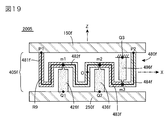
- the first outer arm-shaped graphic (481f) arranged along the section from the first force receiving point (P1) of the connection path (R9) to the first relay point (m1) of the elastic deformation part graphic (480f).
- a first inner arm graphic (482f) arranged along the section from the first relay point (m1) to the second relay point (m2) of the connection route (R9), and the connection route (R9) From the second inner arm figure (483f) arranged along the section from the second relay point (m2) to the third relay point (m3) and the third relay point (m3) of the connection route (R9) And a second outer arm graphic (484f) arranged along a section reaching the second force receiving point (P2).
- connection end of the first pedestal figure (426f) is connected to the lower part of the elastic deformation part figure (480f) near the first relay point (m1), and the connection end of the second pedestal figure (436f) is elastic.
- the deformed portion graphic (480f) is connected below the second relay point (m2), and the connection end of the third pedestal graphic (496f), which is a cross section of the third pedestal, is the elastic deformed portion graphic (480f). Is connected above the vicinity of the third relay point (m3).
- a U-shaped first U-shaped detour (U1) is provided in a section between the first force receiving point (P1) and the first relay point (m1) of the connection path (R7).
- 1 outer arm figure (411f) has a first U-shaped detour along the first U-shaped detour
- a U-shaped second U-shaped detour (U2) is provided in a section between the second relay point (m2) and the second power receiving point (P2) of the connection path (R7).
- the two outer arm-shaped figure (413f) has a second U-shaped detour along the second U-shaped detour.
- a first U-shaped detour (U1) and a second U-shaped detour (U2) have a pair of vertical detours parallel to the Z axis and a lateral detour parallel to the X axis connecting the pair of vertical detours. It is configured by combination with roads.
- All or part of the first outer arm graphic (441f; 451f), the inner arm graphic (442f; 452f), and the second outer arm graphic (443f; 453f) are related to the direction orthogonal to the connection path.
- a narrowed portion (41 to 43; 51a, 51b, 52a, 52b, 53a, 53b) having a narrow width is provided.
- Weight adjustment part graphic projecting in the direction perpendicular to the connection path on all or part of the first outer arm graphic (461f), the inner arm graphic (462f), and the second outer arm graphic (463f) (62f) is provided.
- connection portion of the first outer arm shape graphic (461f) to the power receiving body graphic (150f) and the connection portion of the second outer arm shape graphic (463f) to the power receiving body graphic (150f) are orthogonal to the connection path.
- a flange portion graphic (61f, 63f) protruding in the direction is provided.
- connection end of the first pedestal graphic (320f) and the second pedestal graphic (330f) to the elastic deformation graphic (310f) constitutes a narrowed graphic that is narrower than other parts. It is.
- the force receiving body (100) and the support body (200) are configured by plate-like members having an upper surface and a lower surface parallel to the XY plane.
- the elastic deformation portion (310) is configured by a structure in which an elongated arm-like member is bent.
- the detection element detects the deformation state of the deformable body by electrically detecting the expansion / contraction state of a predetermined portion of the elastic deformation portion.
- the detection element detects the displacement state of the deformation body by electrically detecting the distance between the predetermined position of the elastic deformation portion and the predetermined position of the support.
- the detection element is constituted by a plurality of capacitive elements having a displacement electrode formed at a predetermined position of the elastic deformation portion and a fixed electrode formed at a position facing the displacement electrode of the support,
- the detection circuit performs an arithmetic process based on the capacitance values of a plurality of capacitive elements, thereby outputting an electric signal indicating the force Fz in the Z-axis direction and the moment My around the Y-axis.
- the deformable body (500) is connected to the force receiving body (150) at a predetermined location and the elastic deformation portion (510) with respect to the X-axis causing elastic deformation, and the predetermined location of the elastic deformation portion with respect to the X-axis is the support (250)
- a power receiving body figure (150 fx) about the X axis When the basic structure is cut by the XZ plane or a plane parallel to the XZ plane, the geometrical figure that appears on the cross section of the power receiving body is called a power receiving body figure (150 fx) about the X axis.
- the deformed body graphic relating to the X axis relates to the elastic deforming part graphic (510f) relating to the X axis which is a cross section of the elastic deforming part (510) relating to the X axis and the X axis being a cross section of the first pedestal part (520) relating to the X axis.
- a first pedestal graphic (520f) and a second pedestal graphic (530f) for the X axis which is a cross-section of the second pedestal (530) for the X axis
- the basic structure is cut by the YZ plane or a plane parallel to the YZ plane, the geometrical figure that appears in the cross section of the power receiving body is called a power receiving body figure (150fy) with respect to the Y axis.
- the deformed body figure relating to the Y axis relates to the elastically deforming part figure (540f) relating to the Y axis, which is a cross section of the elastically deforming part (540) relating to the Y axis, and the Y axis corresponding to the cross section of the first base part (550) relating to the Y axis.
- the elastic deformation portion graphic (510f) related to the X axis includes the first force receiving point (P11) related to the X axis defined on the contour of the force receiving body graphic (150fx) related to the X axis and the second power receiving point (related to the X axis ( It is arranged along a connection path (R10) related to a predetermined X axis connecting P12), and is a graphic connecting the first force receiving point (P11) related to the X axis and the second force receiving point (P12) related to the X axis.
- the first pedestal graphic (520f) related to the X axis becomes an elastic deformation graphic (510f) related to the X axis in the vicinity of the first relay point (m11) related to the X axis defined on the connection path (R10) related to the X axis.
- the second pedestal graphic (530f) related to the X axis is connected to the elastic deformation part related to the X axis in the vicinity of the second relay point (m12) related to the X axis defined on the connection path (R10) related to the X axis.
- the elastic deformation portion graphic (540f) related to the Y axis includes a first force receiving point (P21) related to the Y axis defined on the contour of the power receiving body graphic (150fy) related to the Y axis and a second force receiving point (related to the Y axis ( It is arranged along a connection path (R11) related to a predetermined Y axis connecting P22), and is a graphic connecting the first force receiving point (P21) related to the Y axis and the second force receiving point (P22) related to the Y axis.
- the first pedestal graphic (550f) related to the Y axis is changed to the elastic deformation graphic (540f) related to the Y axis in the vicinity of the first relay point (m21) related to the Y axis defined on the connection path (R11) related to the Y axis.
- the second pedestal figure (560f) related to the Y axis is connected to the elastic deformation part related to the Y axis in the vicinity of the second relay point (m22) related to the Y axis defined on the connection path (R11) related to the Y axis.
- the elastic deformation portion (510) related to the X axis connects the first force receiving point (P11) related to the X axis and the second force receiving point (P12) related to the X axis, and the first pedestal portion (520 related to the X axis) ) Connects the vicinity of the first relay point (m11) with respect to the X axis of the elastically deforming portion (510) with respect to the X axis and the first support point (Q11) with respect to the X axis defined on the support (250).
- the second pedestal portion (530) related to the X axis is defined in the vicinity of the second relay point (m12) related to the X axis of the elastic deformation portion (510) related to the X axis and the X axis defined on the support (250).
- the elastic deformation part (540) related to the Y axis connects the first force receiving point (P21) related to the Y axis and the second force receiving point (P22) related to the Y axis, and the first base part (550) related to the Y axis.
- the second pedestal portion (560) related to the Y axis is defined in the vicinity of the second relay point (m22) related to the Y axis of the elastic deformation portion (540) related to the Y axis and the Y axis defined on the support (250).
- the first force receiving point (P11) with respect to the X axis is disposed at a position having a negative X coordinate value
- the second force receiving point (P12) with respect to the X axis is disposed at a position having a positive X coordinate value
- the first force receiving point (P21) related to the Y axis is arranged at a position having a negative Y coordinate value
- the second force receiving point (P22) related to the Y axis is arranged at a position having a positive Y coordinate value.
- the first pedestal portion (520 related to the X axis) is located near the first relay point (m11) related to the X axis of the elastic deformation portion (510) related to the X axis with the connection point with the first pedestal portion (520) related to the X axis as a fulcrum.
- the first pedestal portion (550) related to the Y-axis with the vicinity of the first relay point (m21) related to the Y-axis of the elastic deformation portion (540) related to the Y-axis serving as a fulcrum at the connection point with the first pedestal portion (550) related to the Y-axis )
- the vicinity of the second relay point (m22) related to the Y-axis of the elastically deformable portion (540) related to the Y-axis is a connection point with the second pedestal (560) related to the Y-axis.
- the detection circuit (900) shows the force Fz in the Z-axis direction and the moment My around the Y-axis acting on the other in a state where a load is applied to one of the force receiving body and the support body.
- an electrical signal indicating the moment Mx about the X axis is further output.
- the elastic deformation part (510) with respect to the X axis is constituted by a structure obtained by bending an elongated arm-like member arranged on the XZ plane, and the elastic deformation part (540) with respect to the Y axis is arranged on the YZ plane.
- the elastic deformable portion (510) related to the X axis and the elastic deformable portion (540) related to the Y axis are fused at a position intersecting the Z axis. It is what you have.
- the deformed figure (500fx) related to the X axis is a cross-sectional figure obtained when the deformed object (500) is cut along the XZ plane, and the deformed figure (500fy) related to the Y axis is the deformed object (500) drawn from the YZ plane.
- the elastic deformation portion graphic (510f) related to the X axis and the elastic deformation portion graphic (540f) related to the Y axis are both symmetrical about the Z axis, and the elastic deformation portion graphic (510f) related to the X axis and the elastic deformation portion related to the Y axis.
- the figure (540f) is a geometric congruent figure, and is obtained by rotating the congruent figure about the Z axis as the central axis by the elastically deforming part (510) relating to the X axis and the elastic deforming part (540) relating to the Y axis.
- a pedestal graphic group related to the X axis constituted by a first pedestal graphic (520f) related to the X axis and a second pedestal graphic (530f) related to the X axis, a first pedestal graphic (550f) related to the Y axis, and the Y axis
- the pedestal part graphic group related to the Y axis constituted by the second pedestal part graphic (560f) with respect to each other has a symmetrical shape about the Z axis, and the pedestal part graphic group related to the X axis and the pedestal part graphic group related to the Y axis
- a first U-shape related to the X-axis that forms a U-shape in a section between the first force-receiving point (P11) related to the X-axis of the connection path (R10) related to the X-axis and the first relay point (m11) related to the X-axis.
- a detour (U11) is provided, and in the section between the second relay point (m12) regarding the X axis and the second force receiving point (P12) regarding the X axis of the connection path (R10) regarding the X axis, A second U-shaped detour (U12) with respect to the X-axis, A first U-shape related to the Y-axis that forms a U-shape in a section between the first force-receiving point (P21) related to the Y-axis of the connection path (R11) related to the Y-axis and the first relay point (m21) related to the Y-axis.
- a detour (U21) is provided, and in the section between the second relay point (m22) for the Y axis of the connection path (R11) for the Y axis and the second force receiving point (P22) for the Y axis, U A second U-shaped detour (U22) with respect to the Y-axis,
- the sensing element The first displacement electrode (E11) fixed to the bottom surface of the portion disposed along the first U-shaped detour (U11) with respect to the X axis in the elastic deformation section (510) with respect to the X axis, and the support (250 ) And a first fixed electrode (E21) fixed to a portion facing the first displacement electrode on the upper surface of the first capacitive element (C1), A second displacement electrode (E12) fixed to the bottom surface of the portion disposed along the second U-shaped detour (U12) with respect to the X axis in the elastic deformation portion (510) with respect to the X axis, and a
- an auxiliary structure for a force sensor is constituted by the same structure as the deformation body in the force sensor according to the first to twenty-second aspects described above.
- the coordinate system is defined such that the Z axis is a vertical axis, a force receiving body (5100) disposed on the Z axis, a support body (5200) disposed below the power receiving body, and a force receiving force
- a detection deformable body (5300) that connects the body and the support body and causes elastic deformation at least partially by the action of force or moment, and an auxiliary structure body (5401) connected between the power receiving body and the support body ⁇ 5404), a detection element for detecting the deformation or displacement of the detection deformable body or the displacement of the force receiving body or the support,
- a thirty-fifth aspect of the present invention includes a force receiving body (5100), a support body (5200), and a deformation body for detection (5300) connecting the force receiving body and the support body, In the auxiliary structure (5400) used as a part of a component incorporated in a force sensor that detects the applied force or moment by detecting the elastic deformation of the detecting deformation body caused by the action of the force or moment.
- the elastically deforming portion (5410) is a structure that at least partially undergoes elastic deformation, and a first force receiving point (P1) for fixing to the first location of the force receiving member (5100) is provided at one end thereof. The other end is provided with a second force receiving point (P2) for fixing to the second position of the force receiving body (5100), and is a predetermined connecting the first force receiving point and the second force receiving point.
- An arm-like structure along the connection path (R12) of One end of the first pedestal portion (5420) is connected to the elastic deformation portion (5410) in the vicinity of the first relay point (m1) defined on the connection path (R12), and the other end is supported at the other end.
- a first support point (Q1) is provided for fixing to the first location of the body (5200);
- One end of the second pedestal portion (5430) is connected to the elastic deformation portion (5410) in the vicinity of the second relay point (m2) defined on the connection path (R12), and the other end is supported at the other end.
- a second support point (Q2) is provided for fixing to the second location of the body (5200);
- the first force receiving point (5410) of the elastic deformation portion (5410) When a force is applied to P1) and the second force receiving point (P2), the vicinity of the first relay point (m1) of the elastically deformable portion (5410) is a fulcrum at the connection point with the first pedestal portion (5420).
- the second pedestal (5420) is located near the second relay point (m2) at the connection point with the second pedestal (5430) as a fulcrum. It swings with respect to the part (5430).
- a thirty-sixth aspect of the present invention is the auxiliary structure for a force sensor according to the thirty-fifth aspect
- the connection path (R12) is provided on the VW plane of the VW two-dimensional orthogonal coordinate system
- the elastic deformation portion (5410) forms an arm-like structure extending along the VW plane
- the origin (G) of the VW two-dimensional orthogonal coordinate system is defined at the center of gravity
- the first force receiving point (P1) is located in the second quadrant of the VW two-dimensional orthogonal coordinate system
- the second force receiving point (P2 ) Is located in the first quadrant of the VW two-dimensional orthogonal coordinate system
- the first support point (Q1) is located in the third quadrant of the VW two-dimensional orthogonal coordinate system
- the second support point (Q2) is VW two-dimensional orthogonal.
- a thirty-seventh aspect of the present invention provides an auxiliary structure for a force sensor according to the thirty-sixth aspect described above. It is constituted by a plate-like member having an upper surface composed of a plane parallel to the VW plane and a lower surface composed of a plane parallel to the VW plane. (38) According to a thirty-eighth aspect of the present invention, in the auxiliary structure for a force sensor according to the thirty-sixth or thirty-seventh aspect described above, The first traveling path (r1) in which the connection path (R12) travels in the negative direction of the W axis when the connection path (R12) is traced from the first relay point (m1) toward the second relay point (m2).
- the first traveling path (r1) or the second traveling path (r2) is a path passing through the origin (G) of the VW two-dimensional orthogonal coordinate system.
- connection path (R12) has a longitudinal path parallel to the W axis and a lateral path parallel to the V axis;
- a vertical path extends from the first force receiving point (P1) and the second force receiving point (P2), and the first relay point (m1) and the second relay point (m2) are defined on the horizontal path. It is what I did.
- a forty-first aspect of the present invention is the auxiliary structure for a force sensor according to the thirty-sixth to fortieth aspects described above,
- a U-shaped first U-shaped detour (U1) is provided in a section between the first force receiving point (P1) and the first relay point (m1) of the connection path (R12),
- a U-shaped second U-shaped detour (U2) is provided in the section between the second relay point (m2) and the second force-receiving point (P2) of the route (R12).
- a first U-shaped detour (U1) and a second U-shaped detour (U2) have a pair of vertical detours parallel to the W axis and a lateral detour parallel to the V axis connecting the pair of vertical detours. It is configured by combination with roads.
- a constricted portion (54; 55) having a narrow width in the direction orthogonal to the connection path (R12) is provided in a part of the arm-like structure constituting the elastically deformable portion (5410; 5510). .
- a weight adjusting part (62) protruding in a direction orthogonal to the connection path (R12) is provided at a specific location of the arm-like structure constituting the elastic deformation part (5410; 5510).
- Constriction tips in the auxiliary structure for a force sensor according to the 36th to 44th aspects described above, Constriction tips (5421, 5431;) having narrower connection ends of the first pedestal portion (5420; 5520) and the second pedestal portion (5430; 5530) with respect to the elastic deformation portion (5410; 5510) than the other portions. 5521, 5531).
- Constriction tips in the force sensor (5000) in which the auxiliary structure for the force sensor according to the 36th to 45th aspects described above is incorporated as a part of a component.
- the first force receiving point (P1) and the second force receiving point (P2) of the auxiliary structure are joined to the lower surface of the force receiving member (5100), and the first support point (Q1) and the second support of the auxiliary structure are provided.
- the point (Q2) is joined to the upper surface of the support (5200).
- the force receiving body (5100) and the support body (5200) are constituted by plate members having an upper surface and a lower surface parallel to the XY plane, and the Z axis passes through the force receiving body (5100) and the support body (5200).
- Four auxiliary structures are incorporated so as to surround the deformation body (5300) for detection connecting the force receiving body (5100) and the support body (5200),
- the first auxiliary structure (5401) is arranged at a position where its VW plane intersects with the positive X axis in a direction in which the V axis is parallel to the Y axis and the W axis is parallel to the Z axis.
- the second auxiliary structure (5402) is disposed at a position where the VW plane intersects the positive Y axis, in a direction in which the V axis is parallel to the X axis and the W axis is parallel to the Z axis.
- the third auxiliary structure (5403) is arranged at a position where its VW plane intersects with the negative X axis in a direction in which the V axis is parallel to the Y axis and the W axis is parallel to the Z axis.
- the fourth auxiliary structure (5404) is arranged at a position where its VW plane intersects with the negative Y axis, with the V axis parallel to the X axis and the W axis parallel to the Z axis.
- the first force receiving point (P1) and the second force receiving point (P2) of each auxiliary structure are joined to the lower surface of the force receiving body (5100), and the first support point (Q1) and Two support points (Q2) are joined to the upper surface of the support (5200).
- the force sensor according to the present invention employs a structure in which two relay points of the elastically deforming portion whose both ends are connected to the force receiving body are fixed to the support body by the pedestal portion, and thus acts on the force receiving body.
- a drag that prevents the deformation of the elastically deformable portion can be selectively applied. Therefore, it is possible to provide a force sensor that can easily adjust the balance between the moment detection sensitivity and the force detection sensitivity at the time of design.
- An auxiliary structure for a force sensor according to the present invention includes an elastic deformation portion for connecting both ends to a force receiving body, and a pedestal portion for fixing the two relay points to the support.
- the force sensor that incorporates the auxiliary structure is employed, a drag force that prevents deformation of the elastically deformable portion can be selectively applied according to the type of external force that has acted on the force receiving body. it can. Therefore, it is possible to provide a force sensor that can easily adjust the balance between the moment detection sensitivity and the force detection sensitivity at the time of design.
- FIG. 1 is a front view showing the principle of detection of force and moment by a conventional force sensor using a pair of columnar members.
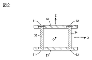
- FIG. 2 is a front sectional view showing a structure of a conventional force sensor that employs a structure in which the upper and lower sides of a columnar member are supported by a diaphragm.
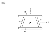
- FIG. 3 is a front view showing a structure of a conventional force sensor in which a pair of columnar members are arranged in an inclined state.
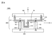
- FIG. 4 is a front view of a basic structure for a force sensor according to a basic embodiment of the present invention.
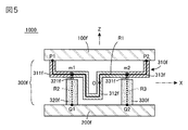
- FIG. 5 is a front sectional view showing a section obtained by cutting the basic structure shown in FIG. 4 along the XZ plane.
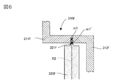
- FIG. 6 is a partially enlarged front sectional view in which a part of FIG. 5 is enlarged.
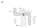
- FIG. 7 is an approximate cross-sectional view for explaining the rocking displacement of the portion shown in FIG.
- FIG. 8 is a front view showing a deformed state of each part when a downward force -Fz is applied to the force receiving body 100 in the basic structure shown in FIG.
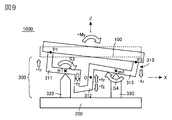
- FIG. 9 is a front view showing a deformed state of each part when a clockwise moment + My acts on the force receiving body 100 in the basic structure shown in FIG.
- FIG. 10 is a front cross-sectional view (showing a cross section taken along the XZ plane) for explaining the structure of the inner arm portion 312 in the basic structure shown in FIG. FIG.
- FIG. 11 is a front sectional view (showing a section cut along the XZ plane) for explaining a first modification of the basic structure shown in FIG.
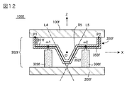
- FIG. 12 is a front sectional view (showing a section cut along the XZ plane) for explaining a second modification of the basic structure shown in FIG.
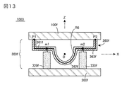
- FIG. 13 is a front sectional view (a section cut along the XZ plane) for explaining a third modification of the basic structure shown in FIG.
- FIG. 14 is a front cross-sectional view (showing a cross section taken along the XZ plane) for explaining a fourth modification of the basic structure shown in FIG.
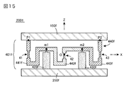
- FIG. 15 is a front sectional view (showing a section cut along the XZ plane) for explaining a fifth modification of the basic structure shown in FIG. FIG.
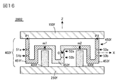
- FIG. 16 is a front sectional view (showing a section cut along the XZ plane) for explaining a sixth modification of the basic structure shown in FIG.
- FIG. 17 is a front sectional view (showing a section cut along the XZ plane) for explaining a seventh modification of the basic structure shown in FIG.
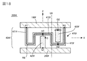
- FIG. 18 is a front sectional view (showing a section cut along the XZ plane) for explaining an eighth modification of the basic structure shown in FIG.
- FIG. 19 is a front sectional view (showing a cross section taken along the XZ plane) for explaining a ninth modification of the basic structure shown in FIG. FIG.
- FIG. 20 is a cross-sectional view and a block diagram showing the configuration of the force sensor according to the basic embodiment of the present invention (the basic structure is cut in the XZ plane).
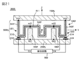
- FIG. 21 is a cross-sectional view and a block diagram showing the configuration of the force sensor according to the basic embodiment of the present invention (a side cross-sectional view of the basic structure cut along the YZ plane).
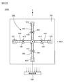
- FIG. 22 is a top view and a block diagram showing a first three-dimensional structure example of the force sensor according to the basic embodiment of the present invention (the top view shows a state where the force receiving body 150 is removed). .
- FIG. 21 is a cross-sectional view and a block diagram showing the configuration of the force sensor according to the basic embodiment of the present invention (the basic structure is cut in the XZ plane).
- FIG. 21 is a cross-sectional view and a block diagram showing the configuration of the force sensor according to the basic embodiment of the present invention (a side cross-sectional view of the basic structure cut along the YZ
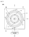
- FIG. 23 is a top view and a block diagram showing a second three-dimensional structure example of the force sensor according to the basic embodiment of the present invention (the top view shows a state where the force receiving body 150 is removed).
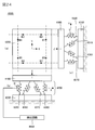
- FIG. 24 is a schematic diagram showing a configuration of a conventional general force sensor (FIG. 24A is a top view of a support, FIG. 20B is a front view, and FIG. 14C is a side view).
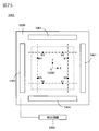
- FIG. 25 is a top view and a block diagram showing a configuration of a force sensor incorporating an auxiliary structure according to the present invention.
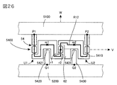
- FIG. 26 is a front view of a more practical embodiment of the auxiliary structure according to the present invention.
- FIG. 27 is a front view of a modification of the auxiliary structure shown in FIG. FIG.
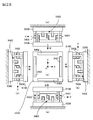
- FIG. 28 is a view showing a specific arrangement of four sets of auxiliary structures in the force sensor shown in FIG. 25 (FIG. 28 (a) is a top view, FIG. 28 (b) is a right side view, and FIG. 20 (c)). Is a rear view, FIG. (D) is a left side view, and FIG. (E) is a front view).
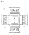
- FIG. 29 is a diagram showing a deformation mode of the four sets of auxiliary structures when a force -Fz in the negative Z-axis direction is applied to the force receiver in the force sensor shown in FIG. 25 (FIG. 29A).
- (B) is a right side view
- (c) is a rear view
- (d) is a left side view
- (e) is a front view).
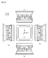
- FIG. 30 is a diagram showing deformation modes of the four sets of auxiliary structures when the force + Fz in the Z-axis positive direction is applied to the force receiving body in the force sensor shown in FIG. 25 (FIG. 30 (a) is a top view).
- (B) is a right side view
- (c) is a rear view
- (d) is a left side view
- (e) is a front view).
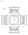
- FIG. 31 is a diagram showing deformation modes of four sets of auxiliary structures when a moment + My about the Y-axis positive direction acts on the force receiving body of the force sensor shown in FIG. 25 (FIG. 31 (a) is a top view).
- FIG. 32 is a view showing a deformation mode of four sets of auxiliary structures when force + Fx in the X-axis positive direction is applied to the force receiving body in the force sensor shown in FIG. 25 (FIG. 32 (a) is a top view).
- (B) is a right side view, (c) is a rear view, (d) is a left side view, and (e) is a front view).
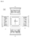
- FIG. 33 is a diagram showing a deformation mode of the four sets of auxiliary structures when a moment + Mz around the Z-axis is applied to the force receiving body in the force sensor shown in FIG.
- FIG. 33A is a top view.
- (B) is a right side view,
- (c) is a rear view,
- (d) is a left side view, and
- (e) is a front view).
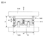
- FIG. 34 is a front view showing the configuration of each part of the auxiliary structure shown in FIG. 26 (hatching is for showing regions of each part, not showing a section).
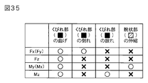
- FIG. 35 is a table showing deformation modes that occur in each part when a force in each axial direction and a moment around each axis act on the auxiliary structure shown in FIG.
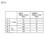
- FIG. 36 compares the detection values obtained when the force in each axial direction and the moment about each axis act on the conventional force sensor shown in FIG. 24 and the force sensor according to the present invention shown in FIG. It is a table to do.
- FIG. 1 is a front view showing the principle of detection of force and moment by the force sensor disclosed in Patent Document 1. As shown in FIG. As shown in FIG.
- the basic structure constituting the mechanical structure of the force sensor is composed of a force receiving body 10, a support body 20, and deformation bodies 31 and 32.
- the origin O is the center position of this basic structure
- the X axis is the right direction in the figure
- the Z axis is the upward direction in the figure
- the Y axis is the vertical direction in the drawing.
- the force receiving body 10 and the support body 20 are both constituted by plate-like members having upper and lower surfaces parallel to the XY plane
- the deformable bodies 31 and 32 are constituted by a pair of columnar members. Yes.
- the deformable bodies 31 and 32 are columnar members that connect the force receiving body 10 and the support body 20, but are made of a material (for example, metal) that causes elastic deformation. Therefore, when an external force is applied to the force receiving body 10 in a state where the support body 20 is fixed (a state where a load is applied), the deformable bodies 31 and 32 are elastically deformed according to the applied external force, and this basic structure Will deform as a whole.
- FIG. 1B is a front view showing a deformed state of the basic structure when a force ⁇ Fz (a force downward in the figure) in the negative Z-axis direction is applied to the force receiving body 10.
- the deformation bodies 31 and 32 are deformed to contract in the vertical direction of the figure, and the force receiving body 10 is displaced downward.
- FIG. 1C is a front view showing a deformed state of the basic structure when a moment around the Y axis (clockwise rotational force in the figure) acts on the force receiving body 10.
- the deformable body 31 extends in the vertical direction in the figure, the deformable body 32 undergoes a deformation that contracts in the vertical direction in the figure, and the force receiving body 10 is tilted to the lower right.
- the deformed state is drawn exaggeratingly, but in actuality, detection is possible even without such a large deformation.
- the origin O of the XYZ three-dimensional orthogonal coordinate system is a point to be defined at the position of the rotation center of the moment acting on the force receiving body 10, and the exact position is actually the basic structure. It is determined by the structure of the whole system in which is incorporated. For example, in a system in which the moment + My acts with a predetermined point in the force receiving body 10 as the rotation center, strictly speaking, it is necessary to handle the predetermined point as the origin O.
- FIG. 1 illustrates a state in which the force ⁇ Fz and the moment + My are applied. However, when the force + Fz is applied, the force receiving body 10 is displaced upward, and when the moment ⁇ My is applied, the force receiving body 10 is left. Inclined down.
- this basic structure is also unique when a force Fx in the X-axis direction, a force Fy in the Y-axis direction, a moment Mx around the X axis, and a moment Mz around the Z axis are applied. It transforms into a state. Also, the amount of deformation in each case depends on the magnitude of the applied force. Therefore, if a detection element for detecting the inherent deformation state and deformation amount is provided, the forces Fx, Fy, Fz in the coordinate axis directions and the moments Mx, My, around the coordinate axes in the XYZ three-dimensional orthogonal coordinate system. It becomes possible to detect Mz.
- a detection circuit that calculates and outputs an electrical signal indicating each axis component based on the detection result of the detection element is added.
- the detection element any deformation that detects deformation or displacement of the deformable bodies 31 and 32 (for example, displacement with respect to the support body 20), displacement of the force receiving body 10 with respect to the support body 20, and displacement of the support body 20 with respect to the force receiving body 10 is detected.
- An element can be used.
- a strain gauge attached to a specific portion of the deformable bodies 31 and 32 can be used.
- a capacitive element constituted by a displacement electrode fixed on the side where displacement occurs and a fixed electrode fixed on the side where no displacement occurs can be used.
- a capacitive element is configured by disposing a displacement electrode fixed at a specific location on the deformable bodies 31 and 32 and a fixed electrode fixed on the support body 20, the capacitance value of the capacitive element is set. As a change in the above, the displacement of the displacement electrode can be electrically detected.
- a six-axis component Fx, Fy, Fz, Mx, My in an XYZ three-dimensional orthogonal coordinate system is formed by configuring a deformed body including four columnar members and using a capacitive element as a detection element. , Mz are separately disclosed. Further, in this document, in order to facilitate the deformation of the deformable body, an example in which a structure in which the upper and lower sides of the columnar member are supported by a diaphragm as shown in the front sectional view of FIG. 2 is also disclosed.
- the columnar member 33 has an upper end connected to the force receiving body 13 through the diaphragm 11 and a lower end connected to the support body 23 through the diaphragm 21.
- the columnar member 34 has an upper end connected to the force receiving body 13 through the diaphragm 12 and a lower end connected to the support body 23 through the diaphragm 22.
- a deformable body is constituted by the columnar members 33 and 34 and the diaphragms 11, 12, 21, and 22. The deformation of the deformable bodies is mainly performed by the diaphragms 11, 12, 21, and 22. It will be brought about by the deformation.
- the detection sensitivity can be adjusted by setting the thickness of the diaphragms 11, 12, 21, and 22. Further, if a capacitive element is formed by the displacement electrodes formed on the diaphragms 11, 12, 21, 22 and the fixed electrode fixed to the support member 23, the displacement of the diaphragm is changed as a change in the capacitance value of the capacitive element. Can be detected. Further, in Patent Document 3 described above, as shown in the front view of FIG. 3, a pair of columnar members 35, 36 constituting a deformed body are formed in an inverted V shape between the force receiving body 15 and the support body 25. There is disclosed a force sensor that is inclined so as to form the following.
- FIGS The basic structure used in the conventional general force sensor has been illustrated in FIGS.
- Each of these basic structures has a structure in which a deformable body is provided between the force receiving body and the support body, and the applied force is detected by detecting the mode of elastic deformation occurring in the deformable body by the detection element. And moment detection.
- the force sensor disclosed in the above-mentioned Patent Documents 1 to 3 it is possible to independently detect the six-axis components Fx, Fy, Fz, Mx, My, Mz in the XYZ three-dimensional orthogonal coordinate system. It is.
- the detection sensitivity of the six-axis component is not necessarily uniform, and if the detection value of the detection element is used as it is, a difference occurs in the detection range of each axis component. Therefore, in practice, it is necessary to perform sensitivity correction by performing an analog amplification process or a digital amplification process for a low-sensitivity axis component, but if such an amplification process is performed, As described above, the error component such as noise is also amplified, resulting in a problem that the detection accuracy is lowered.
- Such a difference in detection sensitivity is particularly prominent between force and moment. As described above, this is because the magnitude of the moment is a value obtained by multiplying the magnitude of the applied external force by the distance from the point of action to the center of rotation (the origin O).
- FIG. 1C shows a state in which the moment + My is directly applied to the force receiving body 10, but this force sensor is used by being incorporated in an input device such as a joystick.
- the power receiving body 10 shown in the figure is attached with an operating rod that protrudes upward, and the user operates the operating rod. Therefore, the longer the operating rod, the greater the value of the acting moment (rotational force around the origin O), and the higher the detection sensitivity of the operation that tilts the operating rod (the operation that generates the moment My).
- the detection sensitivity of the operation of pushing the operating rod downward is constant regardless of the length of the operating rod.
- FIG. 4 is a front view of a basic structure 1000 for a force sensor according to a basic embodiment of the present invention. Similar to the conventional basic structure described in ⁇ 1, the basic structure 1000 includes a force receiving body 100, a support body 200, and a deformable body 300.
- the origin O is the central position of the basic structure 1000
- the X axis is in the right direction in the figure
- the Z axis is in the upward direction in the figure
- the Y axis is in the vertical direction in the drawing.
- the point that the force receiving body 100 and the support body 200 are configured by plate-like members having an upper surface and a lower surface parallel to the XY plane is the same as the conventional basic structure described in ⁇ 1
- the structure of the deformable body 300 is greatly different from the conventional one.
- the deformable body 300 has a predetermined portion connected to the force receiving body 100 and undergoes elastic deformation, and the first pedestal portion 320 that fixes the predetermined portion of the elastic deformable portion 310 to the support 200.
- the elastic deformation portion 310 is configured by a structure in which an elongated arm-like member is bent. The left end is connected to a first force receiving point P1 provided on the left side of the lower surface of the force receiving body 100, and the right end is a force receiving force. It is connected to a second force receiving point P2 provided on the lower right side of the body 100. Therefore, the elastic deformation portion 310 is a member that connects the first force receiving point P1 and the second force receiving point P2.
- the first pedestal part 320 has an upper end connected to the vicinity of the first relay point m1 of the elastic deformation part 310 and a lower end connected to a first support point Q1 provided on the left side of the upper surface of the support body 200.
- it is a member that connects the vicinity of the first relay point m1 of the elastic deformation portion 310 and the first support point Q1 defined on the support 200.
- the second pedestal portion 330 has an upper end connected to the vicinity of the second relay point m2 of the elastic deformation portion 310 and a lower end connected to a second support point Q2 provided on the right side of the upper surface of the support body 200.
- connection route R1 (shown by a thick solid line in the figure) connecting the first force receiving point P1 and the second force receiving point P2 is considered.
- the connection route R1 may be any route as long as it connects the two points P1 and P2, but in the case of the example shown here, it is constituted by a bent route included on the XZ plane.
- the connection path R1 is a path that passes through the origin O of the XYZ three-dimensional orthogonal coordinate system. In FIG.
- connection path R1 serves as a central axis of the elastic deformation part 310, and the elastic deformation part 310 is constituted by an elongated arm-like member extending along the connection path R1.
- the shape of the cross section of the elastic deformation portion 310 (cut surface by a plane orthogonal to the connection path R1) may be a rectangle, a circle, or another arbitrary shape. If necessary, the inside may be constituted by a hollow pipe.
- the material of the elastic deformation part 310 may be any material as long as it is elastically deformed by the action of an external force to be detected.
- the first relay point m1 and the second relay point m2 indicated by x in FIG. 4 are points defined on the connection route R1.
- a portion of the elastic deformation portion 310 arranged in a section from the first force receiving point P1 to the first relay point m1 is referred to as a first outer arm portion 311 and is referred to as the first relay point m1.
- the portion disposed in the section from the second relay point m2 to the second relay point m2 is referred to as the inner arm portion 312 and the portion disposed in the section from the second relay point m2 to the second force receiving point P2 is referred to as the second outer arm portion.
- the first pedestal portion 320 is a connecting member disposed along a first support path R2 (shown by a thick broken line in the drawing) that connects the first relay point m1 and the first support point Q1.
- the second pedestal portion Reference numeral 330 denotes a connection member disposed along a second support path R3 (indicated by a thick broken line in the drawing) that connects the second relay point m2 and the second support point Q2.
- the first support point Q1 is defined immediately below the first relay point m1
- the second support point Q2 is defined immediately below the second relay point m2. 2
- the support path R3 is a straight line parallel to the Z axis.
- the first pedestal part 320 and the second pedestal part 330 can fulfill the function of supporting the elastic deformation part 310 above the support body 200 in the vicinity of the first relay point m1 and the second relay point m2, what will be done? You may comprise with a member of various shapes.
- the first pedestal portion 320 is configured by a columnar structure having the first support path R2 as a central axis, and a first pedestal constriction portion 321 having a small radius is formed at the upper end thereof. Is formed.
- the vicinity of the first relay point m1 of the elastic deformation portion 310 is connected to the upper surface of the first pedestal constriction portion 321.
- the second pedestal portion 330 is configured by a cylindrical structure having the second support path R3 as a central axis, and a second pedestal constriction portion 331 having a small radius is formed at the upper end thereof. .
- the vicinity of the second relay point m2 of the elastic deformation portion 310 is connected to the upper surface of the second pedestal constriction portion 331. Since the first pedestal portion 320 and the second pedestal portion 320 may be either elastically deformed or not, they can be made of any material. However, for commercial use, it is preferable to use a metal or resin that can be easily processed, like the elastic deformation portion 310.
- FIG. 5 is a front sectional view showing a section obtained by cutting the basic structure 1000 shown in FIG. 4 along the XZ plane.
- each geometrical figure that appears on the cross section when each part constituting the basic structure is cut along a predetermined plane and the word “figure” is added to the end of each original part name. It will be referred to by name, and a code obtained by adding a code “f” (meaning “figure”) to the end of the code of each original part will be shown.
- the figure appearing in the cross section of the force receiving body 100 is called a power receiving figure 100f
- the figure appearing in the cross section of the supporting body 200 is called a supporting figure 200f
- a figure appearing in the cross section is called a deformed figure 300f.
- the power receiving body 100 and the support body 200 are both plate-like members whose upper and lower surfaces are parallel to the XY plane, and therefore the power receiving body figure 100f and the support body figure 200f are both illustrated. It becomes a rectangle as follows.
- the deformed body graphic 300f sandwiched between the power receiving body graphic 100f and the support body graphic 200f is the elastic deformed portion graphic 310f that is a cross section of the elastic deformable portion 310 and the cross section of the first pedestal portion 320.
- the figure includes a single pedestal graphic 320f and a second pedestal graphic 330f that is a cross section of the second pedestal 330.
- the elastic deformation portion graphic 310f includes a first outer arm-shaped graphic 311f, an inner arm-shaped graphic 312f, and a second outer arm-shaped graphic 313f.
- connection path R1 is indicated by a bold line.
- This connection route R1 is a broken line-like route connecting the first force receiving point P1 and the second force receiving point P2 defined on the contour of the force receiving body figure 100f, and is included in the route included on the XZ plane.
- the elastic deformation portion graphic 310f is arranged along the broken line-shaped connection path R1, and becomes an arm-shaped graphic connecting the first force receiving point P1 and the second force receiving point P2.
- the first pedestal graphic 320f is a graphic connected to the elastic deformation graphic 310f in the vicinity of the first relay point m1 defined on the connection path R1, and the second pedestal graphic 330f is connected to the connection path R1.
- the graphic is connected to the elastic deformation part graphic 310f in the vicinity of the second relay point m2 defined above.
- the first pedestal portion 320 and the second pedestal portion 330 are members that support the elastic deformation portion 310 from below. Therefore, in the front sectional view of FIG.
- the first pedestal constriction part graphic 321f which is an upper connection end of the elastic deformation part graphic 310f, is connected to a lower part of the elastic deformation part graphic 310f in the vicinity of the first relay point m1, and is a second connection end that is an upper connection end of the second pedestal graphic 330f.
- the base constriction part figure 331f is connected to the lower part of the elastic deformation part figure 310f near the second relay point m2.
- the first pedestal graphic 320f includes a first support point Q1 defined on the outline of the first relay point m1 defined on the connection route R1 and the support graphic 200f.
- first support path R2 shown by a thick broken line in the figure
- second pedestal graphic 330f is connected to a second support path R3 (a second connecting point R2 (the second relay point m2 defined on the connection path R1) and the second support point Q2 defined on the outline of the support graphic 200f. (Shown by a thick broken line in the figure) and becomes a graphic connecting the elastic deformation portion graphic 310f and the support graphic 200f.
- first pedestal narrowing portion 321 is formed at the upper end of the first pedestal portion 320 and the second pedestal narrowing portion 331 is formed at the upper end of the second pedestal portion 330.
- the vicinity of the first relay point m1 of the elastic deformation portion graphic 310f is supported by the narrow first pedestal constriction portion graphic 321f, and the vicinity of the second relay point m2 is It means that it is supported by the narrow second base constriction portion graphic 331f.
- the reason for supporting the elastic deformation portion 310 by narrowing the tip of each pedestal portion is that when an external force is applied to the force receiving body 100, the elastic deformation portion 310 is near the first relay point m1 and the second relay point m2. This is because the vicinity swings with respect to the first pedestal portion 320 and the second pedestal portion 330.
- FIG. 6 is a partially enlarged front sectional view in which a part of FIG. 5 (a vicinity of the first relay point m1) is enlarged.
- transformation aspect of each part when an external force acts on the force receiving body 100 is considered, referring this sectional view.
- the elastic deformation portion graphic 310f is divided into a first outer arm shape graphic 311f located on the left side and an inner arm shape graphic 312f located on the right side of the first relay point m1 as a boundary. Divided.
- the first pedestal graphic 320f is arranged along the first support path R2 that connects the first relay point m1 and the first support point Q1 defined in the outline of the support figure 200f. ing.
- the upper end portion of the first pedestal portion graphic 320f is a portion that functions as a connection end with respect to the elastic deformation portion graphic 310f, but constitutes a narrowed shape that is narrower than the other portions. This is referred to as a pedestal constriction portion graphic 321f.
- the upper end portion of the second pedestal portion graphic 330f is a portion that functions as a connection end with respect to the elastic deformation portion graphic 310f, but constitutes a constricted graphic that is narrower than the other portions.
- the second base stenosis portion graphic 331f will be referred to.
- the upper end portion of the first pedestal portion graphic 320f forms the first pedestal constriction portion graphic 321f
- the first pedestal portion graphic 320f and the elastic deformation portion graphic 310f are in a state close to point contact. Will be connected.
- the upper end portion of the second pedestal portion graphic 330f forms a second pedestal constriction portion graphic 331f
- the second pedestal portion graphic 330f and the elastic deformation portion graphic 310f are connected in a state close to point contact.
- the upper end of the first pedestal portion 320 (first pedestal constriction portion 321) and the lower surface of the elastic deformation portion 310 are connected in a state close to point contact with a small contact area, and the second pedestal portion.
- the upper end (second pedestal constriction 331) of 330 and the lower surface of the elastic deformation part 310 are connected in a state close to a point contact with a small contact area.
- the first pedestal constriction portion graphic 321f is a position of a point m1 ′ (intersection of the first support path R2 and the contour of the elastic deformation portion graphic 310f) on the contour of the elastic deformation portion graphic 310f. It is connected to the.
- this connection form is close to point contact, here, for convenience, both figures are approximated to be in point contact, and the deformation of each part when external force is applied is shown. I'll think about it.
- FIG. 7 is an approximate cross-sectional view showing a state where the above approximation is performed on the portion shown in FIG. Referring to this approximate cross-sectional view, it can be easily understood that the rocking displacement is generated in the elastically deforming portion graphic 310f when an external force is applied. As shown in FIG. 7, if the first base part graphic 320f and the elastic deformation part graphic 310f are in point contact at the connection point m1 ′, the connection point m1 ′ functions as a fulcrum. Referring to the overall structure of the basic structure portion 1000 shown in FIG. 4, when an external force is applied to the force receiving body 100 in a state where the support body 200 is fixed, the external force is changed from the first force receiving point P1 to the first.
- a swing displacement occurs in the vicinity of the first relay point m1 and in the vicinity of the second relay point m2 of the elastic deformation portion 310.
- the first force receiving point P1 is disposed at a position having a negative X coordinate value
- the second force receiving point P2 is disposed at a position having a positive X coordinate value. This point is included as one of the preconditions.
- FIG. 8 is a front view (pedestal portion) showing the deformation state of each part when a downward force -Fz is applied to the force receiving body 100 with the support body 200 fixed to the basic structure 1000 shown in FIG. Is an approximate diagram in which the support by is performed by point contact.
- a downward force -fz (component of force -Fz) acts on the left first outer arm 311 from the force receiving body 100, and the right second outer arm 313.
- a downward force -fz (force-component of Fz) acts on. This is because the force ⁇ Fz applied to the force receiving body 100 is a translational force toward the Z-axis negative direction.
- the vicinity of the first relay point m1 is thus, a counterclockwise oscillating displacement as shown by the white arrow S1 occurs.
- FIG. 8 shows such a deformed state of the basic structure 1000.
- FIG. 9 is a front view showing the deformation state of each part when the moment + My around the Y-axis acts on the force receiving body 100 with the support 200 fixed in the basic structure 1000 shown in FIG. Is an approximate diagram in which the support by is performed by point contact.
- the first force receiving point P1 is arranged at a position having a negative X coordinate value. Therefore, when the moment + My is applied, the force receiving body 100 causes the left first outer arm-shaped portion 311 to move. Therefore, an upward force + fz (moment + My component) is applied.
- the second force receiving point P2 is arranged at a position having a positive X coordinate value, when the moment + My is applied, the force receiving body 100 moves downward from the right second outer arm-shaped portion 313. Force -fz (moment + My component). This is because the moment + My applied to the force receiving member 100 becomes a clockwise rotational force about the origin O.
- the downward force ⁇ fz based on the rocking displacement (white arrow S3) generated in the vicinity of the first relay point m1 and the vicinity of the second relay point m2 are generated.
- the upward force + fz based on the swing displacement (white arrow S4) is in an antagonistic state.
- an antagonistic state is generated by elastic deformation of the inner arm-shaped portion 312.
- a force that extends in the vertical direction in the figure acts, and elastic deformation that extends in the vertical direction in the figure occurs.
- FIG. 9 shows such a deformed state of the basic structure 1000.
- the force in the opposite direction is antagonized, and a force for compressing up and down in the figure acts in the vicinity of the origin O of the inner arm-shaped portion 312 in the direction of compression. Elastic deformation occurs.
- a moment (rotational force) about the Y axis is applied to the force receiving body 100, it is important that a force (+ fz or -fz) in the opposite direction is applied from the left and right of the inner arm portion 312. .
- the force of a reverse direction acts from right and left and it displaces, the inner side arm-shaped part 312 functions as a big resistance element with respect to a displacement.
- the basic structure 1000 shown in FIG. 4 includes the case where the force Fz (translational force) in the Z-axis direction is applied to the force receiving body 100 and the case where the moment My (rotational force) around the Y-axis is applied. It shows a completely different behavior. This is because the elastic deformation portion 310 included in the deformation body 300 constituting the basic structure 1000 has a first force receiving point P1 arranged at a position having a negative X coordinate value and a positive X coordinate value.
- connection path R1 that connects the second force receiving point P2 disposed at a position having a position, and the vicinity of the first relay point m1 and the second relay point m2 on the connection path R1 is This is because it is supported by the first pedestal portion 320 and the second pedestal portion 330 while being swingable in the X-axis direction. Since such a structure is adopted, when a force Fz (translational force) in the Z-axis direction is applied to the force receiving body 100, the inner arm portion 312 that connects the first relay point m1 and the second relay point m2 is used.
- Fz translational force
- a force in the same direction acts from both the left and right ends, but when a moment My (rotational force) around the Y-axis acts on the force receiving body 100, a force in the opposite direction acts from both the left and right ends of the inner arm portion 312. This will occur.
- the inner arm-shaped portion 312 hardly functions as a resistance element that prevents deformation, but in the latter case, the inner arm-shaped portion 312 performs a large function as a resistance element that prevents deformation. This is an essential function of the basic structure 1000 according to the present invention.
- FIG. 10 is a front sectional view for explaining the structure of the inner arm-shaped portion 312 in the basic structure 1000 shown in FIG. 4, and its substantial contents are exactly the same as FIG. However, for convenience of explanation, the Z-axis and the longitudinal axis L1 are drawn with a one-dot chain line.
- connection path R1 is a path included on the XZ plane that connects the first force receiving point P1 and the second force receiving point P2, and the elastic deformation portion 310 is disposed along the connection path R1.
- the inner arm-shaped portion 312 is an arm-shaped member disposed along the section between the first relay point m1 and the second relay point m2 in the connection route R1, and appears in the cross-sectional view of FIG.
- the inner arm-shaped graphic 312f is an arm-shaped graphic that is bent at four points with the connection route R1 connecting the first relay point m1 and the second relay point m2 as the central axis.
- connection route R1 when the connection route R1 is traced from the first relay point m1 toward the second relay point m2, the first horizontal route extending rightward from the first relay point m1 is along the longitudinal axis L1. It can be divided into a downward path going downward, a second horizontal path extending rightward again, an upward path going upward along the Z axis, and a third horizontal path extending rightward again to reach the second relay point m2.
- the inner arm-shaped part graphic 312f arranged along the connection path R1 includes a descending arm-shaped part (part along the longitudinal axis L1) along the descending path and an ascending arm-shaped part (along the longitudinal axis L1).
- U-shaped is not only a curved curved figure, but also bent in a crank shape as shown in the figure
- a graphic having such a U-shaped part U is the inner arm-shaped graphic 312f in order to improve the effect of preventing deformation based on the moment My around the Y axis. The reason for this is that, as shown in FIG.
- the longitudinal direction is vertically This is because if the portion directed in the direction (Z-axis direction) is included, the inner arm-shaped portion can be compressed or extended in the longitudinal direction by a reverse force + fz / ⁇ fz.
- the force required to compress or extend in the longitudinal direction is greater than the force required to bend the elongated arm. Therefore, if a descending arm-like part or an ascending arm-like part facing in the Z-axis direction is provided on a part of the inner arm-like part 312, a resistance that prevents deformation when a moment My around the Y-axis acts.
- connection path R1 is a path that crosses the origin O in the vertical direction (direction parallel to the Z axis).
- FIG. 9 shows an example in which the upward force + fz and the downward force ⁇ fz antagonize when the moment My around the Y-axis acts, with the origin O as the point of interest. This shows a state in which the reverse force + fz / ⁇ fz is antagonizing in the above-described rising arm-like portion (the vicinity of the origin O).
- FIG. 9 shows an example in which the upward force + fz and the downward force ⁇ fz antagonize when the moment My around the Y-axis acts, with the origin O as the point of interest.
- the downward force ⁇ fz acting in the vicinity of the origin O is a force transmitted from the left side starting from the force + fz acting on the first force receiving point P1, and the origin O
- the upward force + fz acting in the vicinity of is a force transmitted from the right side originating from the force -fz acting on the second force receiving point P2.
- connection path R1 is a path that passes through the origin O as in the example shown in the drawing
- the rising arm-like part that is antagonized by the reverse force + fz / ⁇ fz is arranged at the position of the origin O, so the left side
- the force transmitted from the right side and the force transmitted from the right side can be antagonized with good balance in the vicinity of the center of the basic structure 1000, which is preferable in stabilizing the deformation mode of the basic structure 1000.
- FIG. 11 is a front sectional view for explaining a first modification of the basic structure 1000 shown in FIG. The only difference between the basic structure 1000 shown in FIG. 10 and the basic structure 1001 shown in FIG.
- the elastic deformation portion graphic 340f is an elongated arm-shaped graphic arranged along the connection path R4, and includes a first outer arm-shaped graphic 341f, an inner arm-shaped graphic 342f, and a second outer arm-shaped. It is constituted by a partial figure 343f.
- first outer arm graphic 341f and the second outer arm graphic 343f are exactly the same as the first outer arm graphic 311f and the second outer arm graphic 313f shown in FIG.
- the only difference between the basic structure 1000 shown in FIG. 10 and the basic structure 1001 shown in FIG. 11 is that the former inner arm-shaped graphic 312f is replaced with the inner arm-shaped graphic 342f in the latter.
- the inner arm-shaped graphic 312f in FIG. 10 and the inner arm-shaped graphic 342f in FIG. 11 both have a similar shape having a U-shaped portion U, and the fundamental difference is that the U-shaped portion It is only arrangement
- the descending arm-shaped part is disposed along the longitudinal axis L1
- the rising arm-shaped part is disposed along the Z-axis
- the inner arm-shaped part 312f of FIG. In the arm-shaped graphic 342f, a descending arm-shaped part is disposed along the longitudinal axis L2, and a rising arm-shaped part is disposed along the longitudinal axis L3.
- the rising arm-like part is arranged along the Z-axis as in the inner arm-like figure 312f in FIG.
- the descending arm-shaped portion is disposed at a position along the longitudinal axis L2 slightly deviated to the left from the Z-axis. It is disposed at a position along the longitudinal axis L3 that is slightly off-right from the axis.
- the longitudinal axes L2 and L3 are both axes on the XZ plane parallel to the Z axis.
- this inner arm-shaped part figure 342f since there is no arm-shaped part extending in the vertical direction at the center position (position along the Z-axis), the force transmitted from the left and right is transmitted to the vertical arm-shaped part at the center position.
- the longitudinal axes L2 and L3 are arranged at positions that are symmetric with respect to the Z axis, the basic structure 1001 can be made symmetric with respect to the YZ plane. The effect of antagonizing the transmitted force with left-right symmetry is obtained.
- FIG. 12 is a front sectional view for explaining a second modification of the basic structure 1000 shown in FIG.
- the only difference between the basic structure 1000 shown in FIG. 10 and the basic structure 1002 shown in FIG. 12 is that the former deformed figure 300f is replaced with the deformed figure 302f in the latter.
- the elastic deformation portion graphic 350f is an elongated arm-shaped graphic arranged along the connection path R5, and includes a first outer arm-shaped graphic 351f, an inner arm-shaped graphic 352f, and a second outer arm-shaped. It is constituted by a partial figure 353f.
- the first outer arm graphic 351f and the second outer arm graphic 353f are exactly the same as the first outer arm graphic 311f and the second outer arm graphic 313f shown in FIG.
- the only difference between the basic structure 1000 shown in FIG. 10 and the basic structure 1002 shown in FIG. 12 is that the former inner arm-shaped graphic 312f is replaced with the inner arm-shaped graphic 352f in the latter.
- the inner arm-shaped graphic 352f of FIG. 12 is a graphic that is symmetric with respect to the Z axis, like the inner arm-shaped graphic 342f of FIG. 11 described as the first modification.
- the descending arm-shaped portion is disposed along the longitudinal axis L2
- the rising arm-shaped portion is disposed along the longitudinal axis L3.
- the descending arm-shaped part is disposed along the longitudinal axis L4, and the ascending arm-shaped part is disposed along the longitudinal axis L5.
- the only difference between them is only the inclination angle of the longitudinal axis. That is, in the inner arm shape graphic 342f in FIG. 11, two longitudinal axes L2 and L3 are defined as axes parallel to the Z axis, whereas in the inner arm shape graphic 352f in FIG.
- Two longitudinal axes L4 and L5 are defined as axes slightly inclined with respect to the Z axis. Both the longitudinal axes L2 and L3 and the longitudinal axes L4 and L5 are common in that they intersect with the XY plane.
- the intersection angle is 90 °
- the inner arm-shaped part graphic 352f is a graphic that is symmetric with respect to the Z axis. Yes.
- the inner arm 352 is When the moment My acts, it can function as a resistance element that prevents deformation.
- the descending arm-like portion arranged along the longitudinal axis L4 and the ascending arm-like portion arranged along the longitudinal axis L5 are arranged in the direction inclined with respect to the Z axis, the Y axis
- the resistance force that prevents the deformation cannot be exhibited to the maximum.
- the force necessary for compressing or extending in the longitudinal direction is larger than the force necessary for bending the elongated arm-shaped member. Therefore, when the maximum resistance force that prevents deformation is required, the longitudinal direction of the descending arm-like part and the ascending arm-like part is set so as to be parallel to the Z-axis as in the example shown in FIG. Is preferred.
- the second modification shown in FIG. 12 is an embodiment that should be adopted when the resistance as that of the first modification is not necessary.
- the various embodiments described so far are connected to the first longitudinal axis L1, L2, L4 intersecting the XY plane in the connection path traced from the first relay point m1 to the second relay point m2. It can be said that the downward path along the XY plane and the upward path along the second longitudinal axes Z, L3, L5 intersecting the XY plane are provided.
- the inner arm-shaped graphic 312f, 342f, 352f appearing in the cross section along the XZ plane has a descending arm-shaped portion along the descending path and an ascending arm-shaped section along the ascent path.
- FIG. 12 is an example in which the first longitudinal axis and the second longitudinal axis are inclined with respect to the Z axis, whereas the embodiment shown in FIGS. This is an example in which one longitudinal axis and the second longitudinal axis are set to axes parallel to the Z axis. From the viewpoint of maximizing the resistance force that prevents deformation when the moment My around the Y axis acts, the first longitudinal axis and the second longitudinal axis are parallel to the Z axis. It is preferable to set. ⁇ 4-3. Third Modification> FIG.
- FIG. 13 is a front sectional view for explaining a third modification of the basic structure 1000 shown in FIG.
- the only difference between the basic structure 1000 shown in FIG. 10 and the basic structure 1003 shown in FIG. 13 is that the former deformed figure 300f is replaced with the deformed figure 303f in the latter. More specifically, since there is no change in the first pedestal graphic 320f and the second pedestal graphic 330f, the difference between them is that the former elastic deformation graphic 310f is replaced by the elastic deformation graphic 360f in the latter. It is only a point. As shown in FIG.
- the elastic deformation portion graphic 360f is an elongated arm-shaped graphic arranged along the connection path R6, and includes a first outer arm-shaped graphic 361f, an inner arm-shaped graphic 362f, and a second outer arm-shaped graphic. It is constituted by a part graphic 363f.
- the first outer arm graphic 361f and the second outer arm graphic 363f are exactly the same as the first outer arm graphic 311f and the second outer arm graphic 313f shown in FIG.
- the only difference between the basic structure 1000 shown in FIG. 10 and the basic structure 1003 shown in FIG. 13 is that the former inner arm-shaped graphic 312f is replaced with the inner arm-shaped graphic 362f in the latter.
- the inner arm-shaped graphic 342f in FIG. 11 is formed by an elongated graphic bent in a crank shape and surrounded by the outline of only a straight line, whereas the inner arm-shaped graphic 362f in FIG. It is formed by an elongated figure that is gently curved and surrounded by a contour including a curve.
- the term “U-shaped” in the present application includes a figure bent in a crank shape like the inner arm-shaped graphic 342f of FIG. 11, but is included in the inner arm-shaped graphic 362f of FIG.
- the “U-shaped” portion is a figure that is curved like a “U”.
- a curved path that curves downward and then upwards is provided in a section between the first relay point m1 and the second relay point m2 of the connection route R6.
- the inner arm-shaped part graphic 362f has a curved part along the curved path.
- the inner arm portion 362 can serve as a resistance element that prevents deformation when the moment My is applied.
- FIG. 14 is a front sectional view for explaining a fourth modification of the basic structure 1000 shown in FIG.
- the first difference between the basic structure 1000 shown in FIG. 10 and the basic structure 2000 shown in FIG. 14 is the overall lateral width.
- the structure of the outer arm-shaped portion is changed, so that the overall width is wide.
- the power receiver figure 100f shown in FIG. 10 is replaced with a wide power receiver figure 150f in FIG. 14, and the support figure 200f shown in FIG. 10 is replaced with a wide support figure 250f in FIG. It has been.
- the force receiving body 150 and the support body 250 in the modification shown in FIG. 14 are both plate-like members whose upper and lower surfaces are parallel to the XY plane, and are essentially the same as the force receiving body 100 and the support body 200 shown in FIG. There is no difference.
- the feature of the fourth modification shown in FIG. 14 is that a deformable body 400 having a wider width is used instead of the deformable body 300 of the basic structure 1000 shown in FIG.
- the deformed figure 400f is a figure including an elastically deformable part figure 410f, a first pedestal part figure 420f, and a second pedestal part figure 430f.
- the elastic deformation portion graphic 410f is an elongated arm-shaped graphic arranged along the connection path R7 connecting the first force receiving point P1 and the second force receiving point P2, and the first outer arm-shaped portion graphic 411f.
- the first pedestal graphic 420f is exactly the same as the first pedestal graphic 320f shown in FIG. 10, and the second pedestal graphic 430f is exactly the same as the second pedestal graphic 330f shown in FIG. . Therefore, the first pedestal portion 420 plays a role of supporting the vicinity of the first relay point m1 of the elastic deformation portion 410 along the first support path R2 toward the support point Q1, and the second pedestal portion 430 is elastic.
- route R3 which goes to the support point Q2 is completely the same as the Example described until now.
- the shape of the section between the first relay point m1 and the second relay point m2 of the connection route R7 shown in FIG. 14 is exactly the same as the shape of the same section of the connection route R1 shown in FIG.
- the shape portion graphic 412f is exactly the same as the inner arm shape portion graphic 312f shown in FIG.
- the elastic deformation part 310 shown in FIG. 10 and the elastic deformation part 410 shown in FIG. 14 differ only in the outer arm-shaped part. That is, the first outer arm graphic 311f shown in FIG. 10 is replaced with the first outer arm graphic 411f shown in FIG. 14, and the second outer arm graphic 313f shown in FIG. 10 is shown in FIG. The second outer arm-shaped graphic 413f is replaced.
- the original role of the first outer arm portion is to connect the first force receiving point P1 and the first relay point m1
- the original role of the second outer arm portion is the second force receiving force.
- the point P2 is connected to the second relay point m2.
- members having cross-sectional shapes such as the first outer arm-shaped graphic 311f and the second outer arm-shaped graphic 313f shown in FIG. 10 are sufficient. It is not necessary to prepare members having cross-sectional shapes such as the first outer arm-shaped graphic 411f and the second outer arm-shaped graphic 413f shown in FIG.
- a first U-shaped detour U1 and a second U-shaped detour U2 are provided on the connection route R7.
- detours U1 and U2 are redundant paths that detour the originally necessary paths, and are not necessary for fulfilling the original role.
- the deformation mode of the deformable body 400 is diversified.
- the deformable body 400 can be deformed into various shapes. In ⁇ 3, with reference to FIG. 8 and FIG. 9, the deformation state when the force Fz in the Z-axis direction and the moment My around the Y-axis act on the force receiving body 100 constituting the basic structure 1000 is described. Indicated.
- the external force acting on the force receiving body 100 is not only the force Fz and the moment My, but also other forces such as the forces Fx and Fy and the moments Mx and Mz.
- the axial component will also act.
- the 6-axis detection type force sensor as disclosed in the above-mentioned Patent Documents 1 to 3, even when any of the 6-axis components Fx, Fy, Fz, Mx, My, and Mz of the external force is applied. It is necessary to cause the deformation body to undergo a predetermined deformation and to detect individual axial components of the applied external force based on the deformation mode.
- the deformable body has a structure having various deformation modes as much as possible.
- a redundant structure in which U-shaped detours U1 and U2 are provided in the connection route R7 is employed. That is, a first U-shaped detour U1 having a U-shape is provided in a section between the first force receiving point P1 and the first relay point m1 of the connection path R7, and the first outer arm-shaped portion.
- the figure 411f has a first U-shaped detour along the first U-shaped detour.
- a U-shaped second U-shaped detour U2 is provided in a section between the second force receiving point P2 and the second relay point m2 of the connection path R7, and the second outer arm shape.
- the partial figure 413f has a second U-shaped detour along the second U-shaped detour. Due to such a redundant structure, the deformable body 400 can take more various deformation modes.
- the first U-shaped detour U1 and the second U-shaped detour U2 are a pair of vertical detours parallel to the Z-axis and the pair of vertical detours. It is configured by a combination with a lateral detour that is parallel to the axis.
- FIG. 15 is a front sectional view for explaining a fifth modification of the basic structure 1000 shown in FIG.
- the basic structure 2001 shown in FIG. 15 is obtained by slightly modifying the basic structure 2000 shown in FIG. That is, the only difference between the basic structure 2000 shown in FIG. 14 and the basic structure 2001 shown in FIG.
- the elastically deformable portion graphic 440f shown in FIG. 15 includes a first outer arm-shaped graphic 441f, an inner arm-shaped graphic 442f, and a second outer arm-shaped graphic 443f as illustrated. Each of these graphics corresponds to the first outer arm-shaped graphic 411f, the inner arm-shaped graphic 412f, and the second outer arm-shaped graphic 413f shown in FIG.
- the first outer arm-shaped graphic 441f (FIG. 15) is obtained by forming the constricted portion 41 on the first outer arm-shaped graphic 411f (FIG. 14), and the inner arm-shaped graphic 442f is an inner arm-shaped.
- the constricted portion 42 is formed on the part graphic 412f, and the second outer arm-shaped graphic 443f is formed by forming the constricted portion 43 on the second outer arm-shaped graphic 413f.
- the constricted portions 41, 42, and 43 are portions where the width in the direction orthogonal to the connection path R7 is narrow, and are more likely to be elastically deformed than other portions. In the embodiment shown in FIG.
- each of the first outer arm-shaped graphic 441f, the inner arm-shaped graphic 442f, and the second outer arm-shaped graphic 443f is provided with a constricted portion. It is not necessary to provide a constricted portion on all of the arm-shaped portion figures 441f, 442f, and 443f, and a constricted portion may be provided on only a part thereof. Further, the constricted portion is not necessarily provided at one place, and may be provided at several places. The reason for providing such a constricted portion is to facilitate elastic deformation of the arm-shaped portions 441, 442, and 443 and diversify the deformation modes of the deformable body 401.
- FIG. 16 is a front sectional view for explaining a sixth modification of the basic structure 1000 shown in FIG.
- the basic structure 2002 shown in FIG. 16 is obtained by slightly changing the position and shape of the constricted portion in the basic structure 2001 shown in FIG. That is, the only difference between the basic structure 2001 shown in FIG.
- the elastically deformable portion graphic 450f shown in FIG. 16 includes a first outer arm-shaped graphic 451f, an inner arm-shaped graphic 452f, and a second outer arm-shaped graphic 453f, as shown.
- the first outer arm graphic 451f is formed with constrictions 51a and 51b
- the inner arm graphic 452f is formed with constrictions 52a and 52b
- the second outer arm graphic 453f is formed.
- the constricted portions 53a and 53b are formed.
- a relatively long constricted portion 41, 42, 43 is formed at one location of each of the arm-shaped portion figures 441f, 442f, 443f
- relatively short constricted portions 51a, 51b, 52a, 52b, 53a, and 53b are formed at two locations on each of the arm-shaped portion figures 451f, 452f, and 453f.
- FIG. 17 is a front sectional view for explaining a seventh modification of the basic structure 1000 shown in FIG.
- the basic structure 2003 shown in FIG. 17 is obtained by slightly modifying the basic structure 2000 shown in FIG. That is, the only difference between the basic structure 2000 shown in FIG. 14 and the basic structure 2003 shown in FIG.
- the elastic deformation portion graphic 460f shown in FIG. 17 includes a first outer arm shape graphic 461f, an inner arm shape graphic 462f, and a second outer arm shape graphic 463f.
- FIG. 14 corresponds to the first outer arm-shaped graphic 411f, the inner arm-shaped graphic 412f, and the second outer arm-shaped graphic 413f, respectively.
- the first additional element is a weight adjustment unit graphic 62f.
- the weight adjustment portion graphic 62f is a graphic (shown with mesh hatching in the figure) protruding below the right horizontal portion of the inner arm-shaped graphic 462f.
- the 2nd additional element is the flange part figures 61f and 63f.
- the flange portion graphic 61f is a graphic provided at the upper end of the first outer arm-shaped graphic 461f (connection portion to the first force receiving point P1)
- the flange graphic 63f is a second outer arm-shaped graphic. It is the figure provided in the upper end part (connection part with respect to 2nd power receiving point P2) of 463f.
- the weight adjustment unit graphic 62f corresponds to a cross-sectional graphic of a part forming the weight adjustment unit 62 in the three-dimensional basic structure 2003.
- the weight adjusting unit 62 is not directly related to the original function of the elastic deforming unit 460, that is, the function of adjusting the balance between the detection sensitivity of the moment and the detection sensitivity of the force. Play a role in coordinating.
- the role can be easily understood by comparing the overall shape of the deformable figure 400f shown in FIG. 14 with the overall shape of the deformed figure 403f shown in FIG.
- a deformable figure 400f shown in FIG. 14 is a figure that is asymmetrical with respect to the Z axis in the figure.
- the deformed figure 403f shown in FIG. 17 is also an asymmetric figure with respect to the Z axis.
- the weight adjustment part figure 62f is added to the deformable figure 403f, the balance of the area on the two-dimensional plane called the cut plane is almost symmetrical with respect to the Z axis. This means that, considering the three-dimensional basic structure 2003, the weight adjusting unit 62 plays a role of balancing the left and right weight balance with respect to the YZ plane.
- the deformable body takes various deformation modes by the action of the six-axis component of the external force. Therefore, it is preferable that the three-dimensional weight distribution of the basic structure 2003 is as symmetric as possible with respect to the coordinate axis. If the weight distribution of the basic structure 2003 is uneven, the deformation operation becomes unstable, and the detection result may be adversely affected.
- the weight adjustment unit 62 plays a role of adjusting the weight distribution of the basic structure 2003 so as not to be biased and enabling stable detection.
- the weight adjustment part graphic 62f is provided in a space beside the inner arm-shaped part graphic 462f, but the place where the weight adjustment part graphic is arranged makes the weight distribution uniform.
- the weight adjustment unit graphic may be added to all of the first outer arm-shaped graphic 461f, the inner arm-shaped graphic 462f, and the second outer arm-shaped graphic 463f, or a part thereof. You may add a weight adjustment part figure. Further, the weight adjusting unit graphic may be a graphic having any shape as long as it projects in a direction orthogonal to the connection path. Next, the role of the flange part figures 61f and 63f will be described.
- the flange part graphic 61f protrudes in a direction orthogonal to the connection path provided at the connection part (in the vicinity of the first power receiving point P1) of the first outer arm graphic 461f to the power receiver graphic 150f.
- the figure corresponds to a cross-sectional figure of a portion forming the flange portion 61 in the three-dimensional basic structure 2003.
- the flange part graphic 63f protrudes in a direction orthogonal to the connection path provided at the connection part (near the second force receiving point P2) of the second outer arm part graphic 463f to the power receiving body graphic 150f.
- connection with respect to the power receiving body 150 can be made firm.
- the elastically deformable portion 460 is configured by an elongated arm-shaped member, the area of the cross section thereof is limited, and thus there may be cases where the joining to the force receiving body 150 is not sufficient. In such a case, if the flange portions 61 and 63 are formed at the end portion of the elastic deformation portion 460, the area of the joint surface can be increased, and a firmer joint can be performed. ⁇ 4-8.
- FIG. 18 is a front sectional view for explaining an eighth modification of the basic structure 1000 shown in FIG.
- the basic structure 2004 shown in FIG. 18 also has a structure in which a deformable body 404 is provided between the force receiving body 160 and the support body 260. Further, the plate member whose upper and lower surfaces are parallel to the XY plane is used as the force receiving member 160 and the support member 260 in the same manner as in the previous embodiments. Therefore, the cross section of the basic structure 2004 cut along the XZ plane is as shown in FIG. 18 in which a rectangular power receiving body graphic 160f, a rectangular supporting body graphic 260f, and a deformable graphic 404f that connects the two. , Is composed of.
- the deformable body graphic 404f includes an elastic deformation portion graphic 470f, a first pedestal portion graphic 425f, and a second pedestal portion graphic 435f.
- the elastic deformation portion graphic 470f includes the first force receiving point P1 and the second power receiving point P1. It is constituted by an elongated arm-shaped figure along the connection path R8 on the XZ plane connecting the force point P2.
- the feature of the embodiment shown in FIG. 18 is the form of support by the first pedestal portion 425 and the second pedestal portion 435. As shown in the drawing, the upper end (connection end) of the first pedestal graphic 425f is connected to the lower part of the elastic deformation graphic 470f near the first relay point m1.
- the 1st base part 425 becomes a member which supports the elastic deformation part 470 from the bottom like the Example described so far.
- the 2nd base part 435 becomes a member which supports the elastic deformation part 470 from upper direction contrary to the Example described so far.
- the second pedestal graphic 435f is a graphic in which the top of the first pedestal graphic 425f is reversed, and the lower end (connection end) of the second pedestal graphic 470f is the second relay point m2 of the elastic deformation graphic 470f. It is connected above the vicinity.
- the upper end of the second pedestal graphic 435f is shown fixed to the second support point Q2 drawn in space, but in reality, this second support point.
- the second pedestal portion 435 is provided in the vicinity of the second relay point m2 of the elastic deformation portion 470 and the support. This is a member that connects the second support point Q2 provided on the upper surface of the body 260. Therefore, the second pedestal portion 435 actually has a U-shaped curved shape, for example, and one end of the second pedestal portion 435 is drawn at the second relay point of the elastic deformation portion 470 as illustrated in the cross-sectional view of FIG. The other end is connected to the second support point Q ⁇ b> 2 provided on the upper surface of the support 260. In the cross-sectional view of FIG.
- the elastic deformation portion graphic 470f is composed of the first outer arm shape graphic 471f, the inner arm shape graphic 472f, and the second outer arm shape graphic 473f, and balances the moment detection sensitivity and the force detection sensitivity.
- the function to adjust can be fulfilled.
- the basic structure 2004 shown in FIG. 18 has a function of adjusting the balance between the detection sensitivity of the moment and the detection sensitivity of the force, like the basic structure 1000 shown in FIG. become. That is, in the case of the basic structure 2004 shown in FIG. 18, when the connection route R8 is traced from the first relay point m1 toward the second relay point m2, it descends downward along the longitudinal axis L6 intersecting the XY plane.
- the inner arm-shaped part graphic 472f has a descending arm-shaped part along the descending path. Therefore, when the moment My around the Y-axis acts, the descending arm-shaped portion functions as a resistance element that antagonizes the reverse force transmitted from the left and right and prevents deformation.
- the longitudinal axis L6 is set to be parallel to the Z axis as described above. In the embodiment described so far, the structure in which both of the two relay points m1 and m2 are supported by the pedestal portion from below is adopted. However, the basic structure 2004 shown in FIG.
- One of m1 and m2 is that one is supported by the pedestal portion from below and the other is supported by the pedestal portion from above. Thus, even if the support position by the pedestal portion is changed from below to above, the essential function of the basic structure remains unchanged as described above.
- the connection end of the first pedestal portion graphic is connected above the vicinity of the first relay point m1 of the elastic deformation portion graphic
- the connection end of the second pedestal portion graphic is the elastic deformation portion. It is connected above the vicinity of the second relay point m2 of the figure.
- FIG. 19 is a front sectional view for explaining a ninth modification of the basic structure 1000 shown in FIG.
- the basic structure 2005 shown in FIG. 19 also has a structure in which a deformable body 405 is provided between the force receiving body 150 and the support body 250.
- the plate member whose upper and lower surfaces are parallel to the XY plane is used as the force receiving member 150 and the support member 250 in the same manner as in the previous embodiments. Therefore, a cross section of the basic structure 2005 cut along the XZ plane is as shown in FIG. 19, a rectangular power receiving body graphic 150 f, a rectangular supporting body graphic 250 f, and a deformed body graphic 405 f connecting the two. , Is composed of.
- the deformable body figure 405f includes an elastic deformation part figure 480f, a first pedestal part figure 426f, and a second pedestal part figure 436f.
- the elastic deformation part figure 480f includes the first force receiving point P1 and the second force receiving force.
- a third pedestal portion 496 is further added in addition to the first pedestal portion 426 and the second pedestal portion 436.
- a connection route R9 is defined as a route on the XZ plane connecting the first force receiving point P1 and the second force receiving point P2, but on this connection route R9,
- a third relay point m3 is further defined between the second relay point m2 and the second force receiving point P2.
- a third pedestal portion 496 is added to support the vicinity of the relay point m3.
- the deformable body 405 further includes a third pedestal portion 496 in addition to the elastic deformation portion 480, the first pedestal portion 426, and the second pedestal portion 436.
- the third pedestal portion 496 is a member that connects the vicinity of the third relay point m3 of the elastic deformation portion 480 and the third support point Q3 defined on the support body 250.
- the elastic deformation portion graphic 480f is a first outer arm-shaped graphic arranged along the section from the first force receiving point P1 to the first relay point m1 of the connection path R9.
- connection end of the first pedestal graphic 426f is connected below the first relay point m1 of the elastic deformation graphic 480f, and the connection end of the second pedestal graphic 436f.
- the connection end of the third pedestal graphic 496f which is a cross section of the third pedestal portion, is connected to the third relay point of the elastic deformation portion graphic 480f. It is connected above the vicinity of m3. Accordingly, also in FIG. 19, for convenience, the state in which the upper end of the third pedestal graphic 496f is fixed to the third support point Q3 drawn in the space is shown.
- the third support point Q3 is a point provided on the upper surface of the support body 250 (for example, a point located in the back of the XZ plane), and the third pedestal portion 496 is in the vicinity of the third relay point m3 of the elastic deformation portion 480.
- the 3rd base part 496 can be comprised by the member which makes the shape curved in U shape.
- one end of the third pedestal portion 496 is connected above the vicinity of the third relay point m3 of the elastic deformation portion 480 as illustrated in the cross-sectional view of FIG. It is connected to the third support point Q3 provided on the upper surface of.
- the third support point Q3 is drawn in the space, and the other end of the third pedestal portion 496 is connected to the third support point Q3.
- the connection route R9 is a route that is bent up and down in the form as shown in the figure.
- the vicinity of the first relay point m1 and the second relay point m2 By adopting a structure in which the vicinity is supported from below and the vicinity of the third relay point m3 is supported from above, each component can be efficiently arranged in the three-dimensional space.
- the point to be noted here is that the balance between the detection sensitivity of the moment and the detection sensitivity of the force is adopted when a configuration in which the vicinity of the three relay points m1, m2, and m3 are respectively supported as in the embodiment shown in FIG.
- the content of the adjustment function is different from the content of the adjustment function in the embodiments described so far.
- the essential function of the basic structure is when the force Fz which is a translational force is applied.
- a moment My which is a rotational force
- it functions as a large resistance element that prevents deformation.
- the principle on which such a function works is as described in ⁇ 3 with reference to FIGS. That is, when a force -Fz that is a translational force is applied to the force receiving body 100, as shown in FIG. 8, a force + fz in the same direction is applied to the inner arm portion 312 from the left and right, When a moment + My that is a rotational force is applied, as shown in FIG.
- the elastic deformation part 480 will work as a big resistance element which prevents a deformation
- a moment My which is a rotational force, acts on the force receiving member 150.
- the first outer arm-shaped graphic 481f is displaced upward.
- the left side of the first relay point m1 is displaced upward, and the right side is displaced downward. Therefore, a downward force -fz is applied to the vicinity of the origin O from the left side.
- the second outer arm-shaped graphic 484f is displaced downward.
- the right side of the third relay point m3 is displaced downward, and the left side is displaced upward.
- the second inner arm-shaped part graphic 483f is displaced upward.
- the right side of the second relay point m2 is displaced upward, while the left side is displaced downward.
- a downward force -fz is applied to the vicinity of the origin O from the right side.
- the elastic deformation portion 480 acts as a large resistance element that prevents deformation when the force Fz is applied.
- the force works in the embodiment that supports the vicinity of the three relay points m1, m2, and m3 shown in FIG. 19, in contrast to the detection sensitivity of the moment My (rotational force), the force works.
- An adjustment function that lowers the detection sensitivity of Fz (translation force) works.
- the elastic deformation portion 310 is configured by a structure in which an elongated arm-like member extending along the connection path R1 is bent.
- the elongate arm-like member may have a rectangular cross section, a circular shape, or another arbitrary shape.
- the inside may be constituted by a hollow pipe.
- the role of the elastic deformation portion 310 in the basic structure 1000 is the balance between the detection sensitivity of the force Fz (translational force) and the detection sensitivity of the moment My (rotational force). Is to adjust.
- Fz translational force
- My rotational force
- an adjustment function that lowers the detection sensitivity of the moment My works compared to the detection sensitivity of the force Fz, but the basic structure shown in the modified example of FIG.
- an adjustment function that lowers the detection sensitivity of the force Fz works compared to the detection sensitivity of the moment My.
- the basic principle that the function of adjusting the detection sensitivity of the force Fz and the moment My works is that the structure that appears in the cross section of the basic structure cut along the XZ plane has the unique features described so far. Because. For example, in the case of the basic structure 1000, each cross-sectional figure that appears in the cross section cut along the XZ plane has the cross-sectional structure shown in the front cross-sectional view of FIG.
- the three-dimensional structure 310 is not necessarily limited to a structure composed of elongated arm-shaped members.
- a three-dimensional solid obtained by translating the elastic deformation portion graphic 310f shown in FIG. 5 in the Y-axis direction (the depth direction in the figure) by substantially the same distance as the depth width of the force receiving body 100 and the support body 200.
- the elastic deformation part 310 may be configured by (a solid body shaped like a flat plate bent).
- the pedestal portions 320 and 330 are also obtained by translating the pedestal portion graphics 320f and 330f shown in FIG.
- a three-dimensional solid is preferable.
- an elastically deformable portion graphic 340f having a symmetrical shape with respect to the Z axis is used, a rotating body obtained by rotating the graphic about the Z axis as a central axis
- the elastic deformation part 340 can also be configured.
- the pedestals 320 and 330 are also constituted by a rotating body having the Z axis as a central axis.
- the basic structure 1001 is constituted by a rotating body obtained by rotating all the cross-sectional figures (100f, 200f, 301f) shown in FIG. Good.
- the force receiving body 100 and the support body 200 are configured by disk-shaped members
- the elastic deformation portion 340 is configured by a circular dish-shaped member
- the pedestal portions 320 and 330 are configured by a common donut-shaped member.
- the member referred to as the “arm-like portion” in the present application does not necessarily need to be a member having a three-dimensional shape in the form of an arm.
- the names of the first outer arm graphic 311f, the inner arm graphic 312f, and the second outer arm graphic 313f are used as the names of the cross-sectional graphics.
- the member whose cross section is the first outer arm-shaped graphic 311f is the first outer arm-shaped part 311
- the member whose cross-section is the inner arm-shaped graphic 312f is the inner arm-shaped part 312
- the cross-section is the second outer arm-shaped graphic 313f.
- the member that becomes is called the second outer arm-shaped portion 313, but these arm-shaped portions 311, 312, and 313 are not necessarily members whose three-dimensional shape is an arm shape, but two-dimensional It is sufficient if the cross-sectional figure has an arm shape.
- FIG. 4 shows an embodiment in which the connection path R1 is defined on the XZ plane, and the elastic deformation portion 310 is configured by an elongated arm-like member extending along the connection path R1, according to the embodiment. It has been described that the detection sensitivity adjustment function as shown in FIGS. 8 and 9 works.
- connection path R1 is not necessarily a path defined on the XZ plane, and may be a path defined on an arbitrary plane parallel to the XZ plane.
- the detection is based on the principle described above. It can be easily understood that the sensitivity adjustment function works. Accordingly, in FIGS. 10 to 19, the characteristics of the basic structure according to various modifications have been described as the characteristics of each cross-sectional figure that appears in the cross section cut along the XZ plane.
- connection path R1 is designed to pass through the origin O. This is a consideration for causing a reverse force + fz / ⁇ fz to antagonize in a vertical arm-shaped portion arranged in the vicinity of the origin O. That is, if such a design is performed, the force transmitted from the left side and the force transmitted from the right side can be antagonized with good balance near the center of the basic structure 1000, and the deformation of the basic structure 1000 can be achieved.
- connection route R1 does not necessarily need to be defined as a route on the XZ plane, and may be defined as a route on the XZ plane or an arbitrary plane parallel to the XZ plane. Therefore, in order to design in such a way that the left and right forces are balanced with each other in the vicinity of the center of the basic structure 1000, the longitudinal axis shown in FIG. 10 (the axis shown as the Z axis in the figure) is not necessarily the Z axis. There is no need to be (axis on the XZ plane), and any axis included in the YZ plane may be used.
- first longitudinal axis and the second longitudinal axis that are parallel to the Z axis are provided on the connection path R1 so that the resistance force that prevents deformation is maximized, and the left and right forces are applied near the center.
- first longitudinal axis or the second longitudinal axis may be an axis included in the YZ plane.
- the material of each part of the basic structure is arbitrary, and in general, it may be configured using metal or resin. ⁇ 4-12.
- a cross-sectional structure cut along an XZ plane or an arbitrary plane parallel to the XZ plane has a structure as shown in FIG. 5 and is cut along a YZ plane or an arbitrary plane parallel to the YZ plane.
- the basic structure adjusts the balance of detection sensitivity of the three-axis components. It has a function. For example, as in the embodiment shown in FIG.
- the elastic deformation portion 310 is constituted by a structure in which an elongated arm-shaped member is bent, two sets of such elastic deformation portions 310 are prepared, If they are combined after being rotated by 90 °, a basic structure having a detection sensitivity adjustment function for three-axis components can be realized.
- the basic structure is constituted by a rotating body obtained by rotating the cross-sectional figure shown in FIG. 11 about the Z axis as a central axis, a cross-sectional shape obtained by cutting the basic structure along the XZ plane; Since the cross-sectional shape obtained by cutting the basic structure along the YZ plane is the one shown in the cross-sectional view of FIG.
- Basic components of force sensor according to the present invention As disclosed in the aforementioned Patent Documents 1 to 3, as a mechanical structure portion, a force receiving body that receives an external force to be detected, a support body for supporting the force receiving body, and a power receiving body A force sensor that employs a basic structure including a deformable body that is provided between the support and the support body and that generates elastic deformation is known.
- the force sensor according to the present invention also employs a basic structure having a force receiving body, a support body, and a deformable body.
- the force sensor according to the present invention is in the direction of each coordinate axis in the XYZ three-dimensional orthogonal coordinate system.
- the sensor has a function of detecting at least the force Fz in the Z-axis direction and the moment My around the Y-axis.
- this force sensor includes a force receiving body 100 arranged on the Z axis when the coordinate system is defined so that the Z axis is a vertical axis.
- the force sensor is configured by further adding a detection element and a detection circuit to the basic structure 1000.
- the detection element may be an element that detects the deformation of the deformable body 300 or may be an element that detects the displacement of the deformable body 300.
- the expansion / contraction state of a predetermined portion of the elastic deformation portion 310 may be electrically detected.
- a strain gauge attached to a specific portion of the elastic deformation portion 310 can be used as the detection element.
- each portion of the elastic deformation portion 310 is inherently strained according to the applied external force. Therefore, if a strain gauge is attached to a predetermined location (a location where expansion and contraction occurs on the surface) of the elastic deformation portion 310, mechanical strain generated in each portion can be electrically detected as a change in the electrical resistance of the strain gauge. It is possible to detect the magnitude of a specific axial component of the applied external force.
- the distance between the predetermined portion of the elastic deformation portion 310 and the predetermined portion of the support body 200 may be electrically detected.
- a plurality of capacitive elements having a displacement electrode formed at a predetermined location of the elastic deformation portion 310 and a fixed electrode formed at a position facing the displacement electrode of the support 200 may be used as the detection element.
- the capacitance value of the capacitive element changes, so that the generated displacement can be electrically detected as a change in the capacitance value.
- the detection circuit can output an electrical signal indicating at least the force Fz in the Z-axis direction and the moment My around the Y-axis by performing arithmetic processing based on the capacitance values of the plurality of capacitive elements.
- Cross-sectional structure of force sensor 3000> Next, the cross-sectional structure of the force sensor 3000 capable of detecting the three-axis components of force Fz, moment Mx, and moment My among the six-axis components in the XYZ three-dimensional orthogonal coordinate system will be described.
- 20 and 21 are a cross-sectional view and a block diagram showing the configuration of such a force sensor 3000.
- FIG. 20 is a front sectional view obtained by cutting a portion of the basic structure of the force sensor 3000 along the XZ plane, and the sectional view illustrated in the upper part of FIG. It is the sectional side view which cut the part of the structure by the YZ plane.
- an XYZ three-dimensional orthogonal coordinate is obtained by taking the origin O at the center position of this basic structure, the X axis in the right direction of the figure, the Z axis in the upward direction of the figure, and the Y axis in the vertical direction in the drawing.
- a system is defined.
- FIG. 20 is a front sectional view obtained by cutting a portion of the basic structure of the force sensor 3000 along the XZ plane, and the sectional view illustrated in the upper part of FIG. It is the sectional side view which cut the part of the structure by the YZ plane.
- an XYZ three-dimensional orthogonal coordinate is obtained by taking the origin O at the center position of this basic structure, the X axis in the right
- the Y axis is taken in the right direction of the figure
- the Z axis is taken in the upward direction of the figure
- the X axis is taken in the direction perpendicular to the drawing sheet.
- the front sectional view in the upper part of FIG. 20 and the side sectional view in the upper part of FIG. 21 are geometrically identical.
- the basic structure shown here has a three-dimensional structure that can obtain the same cross section regardless of whether it is cut along the XZ plane or the YZ plane.
- the illustrated basic structure is close to the basic structure 2000 illustrated in FIG. 14, and includes a force receiving body 150, a support body 250, and a deformable body 500.
- the force receiving body 150 and the support body 250 are configured by plate-like members having an upper surface and a lower surface parallel to the XY plane, similarly to those illustrated in FIG.
- the force receiving body 150 and the support body 250 are each composed of a plate member of the same size having a square plane.
- the deformable body 500 is a three-dimensional structure in which the cross section cut along the XZ plane has the structure shown in FIG. 20, and the cross section cut along the YZ plane has the structure shown in FIG.
- the “member about the X axis” of the deformable body 500 is an elastic deformation portion about the X axis that is elastically deformed by connecting a predetermined location to the force receiving body 150 as shown in FIG. 510, a first pedestal portion 520 related to the X axis and a second pedestal portion 530 related to the X axis, which fix a predetermined portion of the elastic deformation portion 510 related to the X axis to the support body 250.
- the “member related to the Y axis” of the deformable body 500 is the elastic deformation related to the Y axis that is elastically deformed by connecting a predetermined portion to the force receiving body 150 as shown in FIG. Part 540, and a first pedestal part 550 related to the Y axis and a second pedestal part 560 related to the Y axis, which fix a predetermined portion of the elastic deformation part 540 related to the Y axis to the support body 250.
- each geometrical figure that appears on the cross section when each part constituting the basic structure is cut by a predetermined plane is “figure” at the end of the name of each original part.
- the power receiving body figure 150fx for the X axis and the support figure for the X axis it will be called a power receiving body graphic 150fy related to the Y axis, a support graphic 250fy related to the Y axis, and a deformation graphic 500fy related to the Y axis.
- a cross-sectional structure when the basic structure is cut along the XZ plane will be described in detail with reference to a front cross-sectional view shown in the upper part of FIG. As described above, this front sectional view includes the power receiving body graphic 150fx regarding the X axis, the support body graphic 250fx regarding the X axis, and the deformed body graphic 500fx regarding the X axis.
- the deformable figure 500fx related to the X axis includes the elastic deformable part graphic 510f related to the X axis that is a cross section of the elastic deformable part 510 related to the X axis and the first pedestal related to the X axis that is a cross section of the first pedestal 520 related to the X axis.
- the elastic deformation portion graphic 510f related to the X axis is a predetermined connection between the first force receiving point P11 related to the X axis defined on the contour of the force receiving body graphic 150fx related to the X axis and the second force receiving point P12 related to the X axis. This figure is arranged along the connection path R10 related to the X axis and connects the first force receiving point P11 related to the X axis and the second force receiving point P12 related to the X axis.
- first pedestal graphic 520f for the X axis is connected to the elastic deformation graphic 510f for the X axis in the vicinity of the first relay point m11 for the X axis defined on the connection path R10 for the X axis.
- the second pedestal graphic 530f related to the axis is connected to the elastic deformation graphic 510f related to the X axis in the vicinity of the second relay point m12 related to the X axis defined on the connection path R10 related to the X axis.
- this side cross-sectional view includes the power receiving body graphic 150fy related to the Y axis, the support graphic 250fy related to the Y axis, and the deformed graphic 500fy related to the Y axis.
- the deformable figure 500fy related to the Y axis includes the elastic deformable part graphic 540f related to the Y axis that is a cross section of the elastic deformable part 540 related to the Y axis and the first pedestal related to the Y axis that is a cross section of the first pedestal 550 related to the Y axis.
- a second pedestal graphic 560f related to the Y axis which is a cross section of the second pedestal 560 related to the Y axis.
- the elastic deformation portion graphic 540f regarding the Y axis connects a first force receiving point P21 regarding the Y axis defined on the outline of the force receiving body graphic 150fy regarding the Y axis and a second force receiving point P22 regarding the Y axis.
- This figure is arranged along the connection path R11 related to the Y axis and connects the first force receiving point P21 related to the Y axis and the second force receiving point P22 related to the Y axis.
- the first pedestal graphic 550f related to the Y axis is connected to the elastic deformation graphic 540f related to the Y axis in the vicinity of the first relay point m21 related to the Y axis defined on the connection path R11 related to the Y axis.
- the second pedestal graphic 560f related to the axis is connected to the elastic deformation graphic 540f related to the Y axis in the vicinity of the second relay point m22 related to the Y axis defined on the connection path R11 related to the Y axis.
- the deformable body 500 shown here includes an elastic deformation portion 510 related to the X axis, a first pedestal portion 520 related to the X axis, a second pedestal portion 530 related to the X axis, an elastic deformation portion 540 related to the Y axis, and a Y axis.
- This is a member constituted by the first pedestal portion 550 related to the Y axis and the second pedestal portion 560 related to the Y axis.
- the elastic deformation portion 510 related to the X axis connects the first force receiving point P11 related to the X axis and the second force receiving point P12 related to the X axis, and the first pedestal related to the X axis.
- the part 520 connects the vicinity of the first relay point m11 related to the X axis of the elastic deformation part 510 related to the X axis and the first support point Q11 related to the X axis defined on the support body 250
- the two pedestal portions 530 connect the vicinity of the second relay point m12 related to the X axis of the elastic deformation portion 510 related to the X axis and the second support point Q12 related to the X axis defined on the support body 250.
- the elastic deformation portion 540 related to the Y axis connects the first force receiving point P21 related to the Y axis and the second force receiving point P22 related to the Y axis, and the first base portion related to the Y axis.
- 550 connects the vicinity of the first relay point m21 related to the Y axis of the elastic deformation portion 540 related to the Y axis and the first support point Q21 related to the Y axis defined on the support body 250, and the second related to the Y axis.
- the pedestal portion 560 connects the vicinity of the second relay point m22 related to the Y axis of the elastic deformation portion 540 related to the Y axis and the second support point Q22 related to the Y axis defined on the support body 250. Also in the embodiment shown here, as in the embodiments described in ⁇ 2 to ⁇ 4, the connection ends of the pedestal portion graphics 520f, 530f, 550f, and 560f with respect to the elastic deformation portion graphics 510f and 540f are in other portions. Compared to this, a narrowed figure is formed. For this reason, each relay point vicinity of the elastic deformation part is supported so that it may rock
- the vicinity of the second relay point m12 related to the X axis of the elastic deformation portion 510 related to the X axis is the X axis with respect to the second pedestal portion 530 related to the X axis with the connection point with the second pedestal 530 related to the X axis as a fulcrum. Swing in the direction.
- “oscillating in the X-axis direction” means that a rotational motion is performed with an axis passing through the fulcrum and parallel to the Y-axis as a central axis.
- “swing in the Y-axis direction” means that a rotational motion is performed about an axis passing through the fulcrum and parallel to the X-axis.
- the first force receiving point P11 related to the X axis is arranged at a position having a negative X coordinate value
- the second force receiving point P12 related to the X axis has a positive X coordinate value. Placed in position.
- the first force receiving point P21 related to the Y axis is arranged at a position having a negative Y coordinate value
- the second force receiving point P22 related to the Y axis has a positive Y coordinate value. Placed in position.
- the basic structure having such structural features has a function of adjusting the balance between the detection sensitivity of the moment and the detection sensitivity of the force.
- the basic structure shown here since the basic structure shown here has the structure shown in FIG. 20 as a cross section cut along the XZ plane, it is a rotational force compared to the case where a force Fz that is a translational force is applied. When the moment My acts, a large resistance element that hinders deformation acts.
- the basic structure shown here has the structure shown in FIG. 21 as a cross section cut along the YZ plane, the moment as a rotational force is compared with the case where the force Fz as a translational force is applied. Even when Mx acts, a large resistance element that prevents deformation acts.
- the force sensor 3000 has a function of detecting the triaxial components of the force Fz, the moment Mx, and the moment My, but the detection sensitivity of the moments Mx and My is compared with the detection sensitivity of the force Fz. Therefore, the detection sensitivity of the triaxial components Fz, Mx, My can be made as uniform as possible. In the case of the conventional force sensor disclosed in Patent Documents 1 to 3, the detection sensitivity of the moments Mx and My tends to be too high compared to the detection sensitivity of the force Fz. At 3000, such a problem is corrected. ⁇ 5-3. Detection Operation of Force Sensor 3000> Next, a specific detection operation by the force sensor 3000 shown in FIGS. 20 and 21 will be described.
- the force sensor 3000 is configured by adding a detection element and a detection circuit to the basic structure described in ⁇ 5-2.
- the embodiment shown here uses four sets of capacitive elements as detection elements.
- the cross sections of the displacement electrodes E11 to E14 and the fixed electrodes E21 to E24 for configuring the four sets of capacitive elements C1 to C4 are drawn by bold lines. It is.
- the four sets of capacitive elements C1 to C4 serve as detection elements that detect the displacement of a specific portion of the deformable body 500.
- a block showing the detection circuit 900 is drawn.
- This detection circuit 900 is based on the detection results of the detection elements (four sets of capacitive elements C1 to C4), and the three axes of the external force acting on one of the force receiving body 150 and the support body 250 are loaded.
- An electrical signal indicating a component that is, a force Fz in the Z-axis direction, a moment My around the Y-axis, and a moment Mx around the X-axis is output.
- the capacitive elements C1 to C4 shown in the figure are detection elements that detect displacement of the deformable body 500 with respect to the support body 250, but use detection elements that detect displacement of the deformable body 500 with respect to the force receiving body 150. (In this case, the fixed electrode is formed on the force receiving member 150 side).
- a detection element that detects displacement of the force receiving body 150 with respect to the support body 250 and displacement of the support body 250 with respect to the force receiving body 150 (for example, a fixed electrode fixed to the support body 250; A capacitor element may be configured by facing a displacement electrode fixed to the force receiving member 150).
- a detection element that detects displacement of the force receiving body 150 with respect to the support body 250 and displacement of the support body 250 with respect to the force receiving body 150
- a capacitor element may be configured by facing a displacement electrode fixed to the force receiving member 150.
- the counter electrode pair constituted by the displacement electrode E11 and the fixed electrode E21 is referred to as a capacitive element C1, and the capacitance value thereof is also indicated by the same symbol C1, and the displacement electrode E12 and the fixed electrode E22 are illustrated.
- the counter electrode pair constituted by the above is called a capacitive element C2, and the capacitance value thereof is also denoted by the same symbol C2.
- the detection circuit 900 acquires electrical signals indicating these capacitance values C1 and C2.
- the counter electrode pair constituted by the displacement electrode E13 and the fixed electrode E23 is referred to as a capacitive element C3, and the capacitance value thereof is also indicated by the same symbol C3.
- the displacement electrode E14 and the fixed electrode E24 The counter electrode pair constituted by these is called a capacitive element C4, and the capacitance value thereof is also indicated by the same symbol C4.
- the detection circuit 900 acquires an electrical signal indicating these capacitance values C3 and C4.
- the detection circuit 900 is provided with electric signals indicating four sets of capacitance values C1, C2, C3, and C4.
- the section between the first force receiving point P11 related to the X axis of the connection path R10 related to the X axis and the first relay point m11 related to the X axis is the second of the X axis related to the U shape.
- a 1U-shaped detour U11 is provided, and a section between the second relay point m12 regarding the X axis and the second force receiving point P12 regarding the X axis of the connection path R10 regarding the X axis has a U shape.
- a second U-shaped detour U12 related to the X axis is provided. Accordingly, the first outer arm portion 511 related to the X axis has a detour portion along the first U-shaped detour U11, and the second outer arm portion 513 related to the X axis is connected to the second U-shaped detour U12. It has a detour along. Similarly, as shown in FIG.
- the section between the first force receiving point P21 related to the Y axis of the connection path R11 related to the Y axis and the first relay point m21 related to the Y axis is related to the Y axis that forms a U shape.
- a first U-shaped detour U21 is provided, and a U-shaped section is formed in the section between the second relay point m22 regarding the Y axis of the connection path R11 regarding the Y axis and the second force receiving point P22 regarding the Y axis.
- a second U-shaped detour U22 related to the Y axis is provided.
- the first outer arm-shaped portion 541 related to the Y-axis has a bypass portion along the first U-shaped detour U21, and the second outer arm-shaped portion 543 related to the Y-axis is connected to the second U-shaped detour U22. It has a detour along.
- the formation positions of the displacement electrodes E11 to E14 it can be seen that all are formed on the lower surface of the U-shaped detour portion of the outer arm-shaped portion. That is, as shown in FIG.
- the displacement electrode E11 is formed on the bottom surface of the detour portion along the U-shaped detour U11 of the first outer arm-shaped portion 511 with respect to the X axis
- the displacement electrode E12 is 2 formed on the bottom surface of the detour along the U-shaped detour U12 of the outer arm 513.
- the displacement electrode E13 is formed on the bottom surface of the detour portion along the U-shaped detour U21 of the first outer arm-shaped portion 541 with respect to the Y axis
- the displacement electrode E14 is the second electrode with respect to the Y axis. 2 formed on the bottom surface of the detour portion along the U-shaped detour U22 of the outer arm portion 543.
- the deformation mode of the deformable body 500 can be diversified, and the merit that the deformable body 500 can be deformed into various shapes is obtained. This is as already described in ⁇ 4-4.
- the U-shaped detour provided on the outer arm also serves to provide a place for forming the displacement electrode. be able to.
- Capacitance elements C1 to C4 that are optimal for the role as detection elements are obtained. That is, as shown in FIG.
- the first capacitance element C1 is configured by the first fixed electrode E21 fixed to a portion of the upper surface of 250 facing the first displacement electrode E11.
- a second capacitive element C2 is configured by the second fixed electrode E22 fixed to a portion facing the displacement electrode E12.
- the third displacement electrode E13 fixed to the bottom surface of the portion disposed along the first U-shaped detour U21 with respect to the Y axis in the elastic deformation portion 540 with respect to the Y axis, and the support
- a third capacitive element C3 is configured by the third fixed electrode E23 fixed to a portion of the upper surface of the body 250 facing the third displacement electrode E13.
- a fourth capacitive element C4 is configured by the fourth fixed electrode E24 fixed to a portion facing the displacement electrode E14.
- the outer arm portions 511, 513, 541, and 543 are all displaced downward, so the electrode spacing of the four sets of capacitive elements C1 to C4 is as follows. All of them become narrow, and the capacitance values C1 to C4 all increase.
- the outer arm portions 511, 513, 541, and 543 are all displaced upward, and therefore the electrode distance between the four capacitive elements C1 to C4 is All of them expand and the capacitance values C1 to C4 all decrease.
- ⁇ Fz C1 + C2 + C3 + C4
- an electric signal indicating the force Fz can be output.
- FIG. 20 when a clockwise moment + My acts on the force receiving member 150 with the support body 250 fixed, the outer arm portion 511 is displaced upward and the outer arm portion 513 is moved downward.
- the electrode interval of the capacitive element C1 increases, the capacitance value C1 decreases, the electrode interval of the capacitive element C2 decreases, and the capacitance value C2 increases.
- the outer arm portion 511 is displaced downward and the outer arm portion 513 is displaced upward, so that the electrode interval of the capacitive element C1 is increased.
- the capacitance value C1 increases, the electrode interval of the capacitive element C2 increases, and the capacitance value C2 decreases.
- the capacitance value C1 C2 when no force is applied to the force receiving member 150.
- the value of the moment Mx obtained by the calculation process of ⁇ C4 becomes a detection value indicating a correct zero point as it is.
- the detection circuit 900 included in the force sensor 3000 uses the difference between the capacitance value of the first capacitance element C1 and the capacitance value of the second capacitance element C2 as an electrical signal indicating the moment My around the Y axis. And outputs a difference between the capacitance value of the third capacitance element C3 and the capacitance value of the fourth capacitance element C4 as an electric signal indicating the moment Mx around the X axis, and the electrostatic capacitance of the first capacitance element C1.
- the sum of the capacitance value, the capacitance value of the second capacitance element C2, the capacitance value of the third capacitance element C3, and the capacitance value of the fourth capacitance element C4 is output as an electrical signal indicating the force Fz in the Z-axis direction. Will be processed.
- the force sensor 3000 shown in FIGS. 20 and 21 can output detection values of the triaxial components Fz, Mx, and My.
- the detected values of the Fz, Mx, and My axis components obtained by the calculation process are values that do not include other axis components, the detected values of the three axis components are obtained independently without mutual interference. It is possible.
- the balance between the moment detection sensitivity and the force detection sensitivity can be adjusted by using the basic structure shown in FIGS. That is, since the detection sensitivity of the moments Mx and My can be reduced as compared with the detection sensitivity of the force Fz, the detection sensitivity of the three-axis components Fz, Mx, and My can be made as uniform as possible.
- the size of the fixed electrodes E21 to E24 facing each other is larger than the size of the displacement electrodes E11 to E14. This is a consideration for ensuring that the effective facing area is always constant (the area of the displacement electrode is always the effective facing area).
- the deformable body 500 takes various deformation modes, there is a possibility that the displacement position of the displacement electrode and the fixed electrode may be shifted, but the size of the displacement electrode is fixed as in the illustrated example. If the size is slightly smaller than the size of the electrode, the effective facing area that functions as a capacitive element is always constant even when the facing position is displaced. Therefore, the variation in the capacitance value is caused solely by the change in the interelectrode distance between the opposing electrodes. Of course, the size of the fixed electrode may be slightly smaller than the size of the displacement electrode. ⁇ 5-4.
- the effect of making the detection sensitivity of the force Fz and the detection sensitivity of the moment Mx uniform is that the cross-sectional structure when the basic structure is cut along the YZ plane has the unique characteristics shown in FIG. This is an effect that can be obtained. Therefore, as long as each cross-sectional structure is a basic structure having unique characteristics shown in FIGS. 20 and 21, whatever the specific three-dimensional structure is, the triaxial components Fz, Mx, My The effect of equalizing the detection sensitivity is obtained.
- the cross-sectional structure appearing on the XZ cut surface has the characteristics as shown in FIG. 20, and the cross-sectional structure appearing on the YZ cut surface is the characteristic as shown in FIG.
- FIG. 22 is a top view and block diagram showing a force sensor 3001 that is a first embodiment in which the force sensor 3000 shown in FIGS. 20 and 21 is embodied as a three-dimensional structure.
- the top view in the upper part shows the basic structure and the detection element (electrodes constituting the capacitive element) with the force receiving member 150 removed, and the block diagram in the lower part shows the detection circuit 900.
- the X axis is taken in the right direction of the figure
- the Y axis is taken in the upward direction of the figure
- the Z axis is taken in the direction perpendicular to the paper surface.
- the support body 250 is a square substrate, and the deformable body 500 is disposed thereon.
- the Z axis passes through the center of the square support body 250, and the origin O is drawn at the center point of the support body 250.
- a force receiving body 150 made of a square substrate is arranged above the deformable body 500 (front side in the figure). In FIG. The removed state is shown. Of course, if the force receiving member 150 is added to the structure shown in FIG.
- the elastic deformation portion 510 (the cross-sectional figure 510f is shown in FIG. 20) about the X axis is configured by a structure obtained by bending an elongated arm-like member arranged on the XZ plane
- the elastically deforming portion 540 related to the Y-axis (the cross-sectional figure 540f is shown in FIG. 21) is configured by a structure obtained by bending an elongated arm-like member disposed on the YZ plane.
- the elastic deformation portion 510 related to the X axis and the elastic deformation portion 540 related to the Y axis are fused at a position intersecting with the Z axis, and actually form an integrated structure.
- this integrated structure is shown as a cross-shaped member.
- a rectangular column member having a rectangular cross section is used as an elongated arm-like member constituting the elastic deformation portions 510 and 540.
- a cylindrical member having a circular cross section may be used.
- a hollow pipe may be used.
- the constricted portion, the weight adjusting portion, the flange portion, and the like described in the modified examples of ⁇ 4-5, ⁇ 4-6, and ⁇ 4-7 may be used as appropriate.
- the first relay point m11 related to the X axis and the second relay point m12 related to the X axis defined on the connection path R10 (path along the elastic deformation portion 510) related to the X axis are drawn with x marks.
- the first relay point m21 related to the Y axis and the second relay point m22 related to the Y axis defined on the connection path R11 (path along the elastic deformation portion 540) related to the Y axis are also drawn by x.
- each pedestal portion 520, 530, 550, 560 is constituted by a cylindrical structure.
- the upper ends of the pedestal portions 520, 530, 550, and 560 are narrowed, and the lower surfaces of the elastic deformation portions 510 and 540 are supported in a state close to point contact.
- four sets of fixed electrodes E21 to E24 fixed to the upper surface of the support body 250 are depicted.
- each of the fixed electrodes E21 to E24 has a square shape.
- the bottom surfaces of the U-shaped detour portions of the elastically deformable portions 510 and 540 are located, and displacement electrodes E11 to E14 (not shown in the figure) are formed on the bottom surfaces.
- Wiring (not shown) for the detection circuit 900 is applied to the four sets of fixed electrodes E21 to E24 and the four sets of displacement electrodes E11 to E14 (not shown).
- the detection circuit 900 detects the capacitance values of the four sets of capacitive elements C1 to C4 through these wirings, and performs the above-described arithmetic processing to obtain the detection values of the three-axis components Fz, Mx, My. Output. ⁇ 5-5.
- FIG. 23 is a top view and a block diagram showing a force sensor 3002 as a second embodiment in which the force sensor 3000 shown in FIGS. 20 and 21 is embodied as a three-dimensional structure.
- the top view in the upper stage shows the basic structure and the detection element (electrodes constituting the capacitive element) with the force receiving member 150 removed
- the block diagram in the lower stage shows the detection circuit 900.
- the X axis is taken in the right direction of the figure
- the Y axis is taken in the upward direction of the figure
- the Z axis is taken in the direction perpendicular to the paper surface.
- the support body 250 is a square substrate, and the deformable body 500 is disposed thereon.
- the Z axis passes through the center of the square support body 250, and the origin O is drawn at the center point of the support body 250.
- a force receiving body 150 made of a square substrate is arranged above the deformable body 500 (frontward in the figure). In FIG. The removed state is shown.
- the force receiving member 150 is added to the structure shown in FIG. 23 and cut along the XZ plane, the cross-sectional view shown in FIG. 20 is obtained, and if cut along the YZ plane, the cross-sectional view shown in FIG. 21 is obtained. Will be.
- the deformed figure 500fx related to the X axis shown in FIG. 20 is a cross-sectional figure obtained by cutting the deformed object 500 shown in FIG. 23 along the XZ plane, and the deformed figure 500fy related to the Y axis shown in FIG. It is a cross-sectional figure obtained when the deformation body 500 shown in FIG. 23 is cut
- both the force sensor 3001 shown in FIG. 22 and the force sensor 3002 shown in FIG. 23 have the XZ cut surface of the basic structure shown in FIG. 20, and the YZ cut surface shown in FIG. Therefore, there is no difference in that the effect of making the detection sensitivity of the three-axis components Fz, Mx, My uniform is obtained.
- the elastic deformation part 510 (cross-sectional figure 510f is shown in FIG. 20) about the X-axis and the elastic deformation part 540 about the Y-axis (cross-section figure 540f is shown in FIG. 21). Is realized by a common rotating body. As shown in FIGS. 20 and 21, the elastic deformation portion graphic 510 f regarding the X axis and the elastic deformation portion graphic 540 f regarding the Y axis are both symmetrical with respect to the Z axis.
- the elastic deformation portion graphic 510f regarding the X axis and the elastic deformation portion graphic 540f regarding the Y axis are geometrically congruent figures. Therefore, if the integrated elastic deformation portion 570 (see FIG. 23) is formed by a rotating body obtained by rotating the congruent shape about the Z axis, a part of the integrated elastic deformation portion 570 is elastic with respect to the X axis. It functions as the deforming part 510, and another part functions as an elastic deforming part 540 with respect to the Y axis. Similarly, in the case of the force sensor 3002 shown in FIG. 23, the pedestals 520, 530, 550, and 560 are also embodied by a common rotating body. As shown in FIG.
- the pedestal graphic group related to the X axis is Symmetrical shape about the Z axis.
- the pedestal graphic related to the Y axis is considered.
- the group also has a symmetrical shape about the Z axis.
- the pedestal part graphic group related to the X axis and the pedestal part graphic group related to the Y axis are geometrically congruent figures. Therefore, if the integrated pedestal portion 580 (see FIG. 23) is formed by a rotating body obtained by rotating this congruent figure about the Z axis as a central axis, the first pedestal portion 520 relating to the X axis and the second pedestal relating to the X axis.
- the part 530, the first pedestal part 550 related to the Y axis, and the second pedestal part 560 related to the Y axis can be constituted by a part of the integrated pedestal part 580, respectively.
- FIG. 23 is a three-dimensional structure including the integrated elastic deformable portion 570 and the integrated pedestal portion 580 described above.
- Concentric circles drawn by solid lines and broken lines in the figure show the outline and stepped portion of the integrated elastic deformation part 570
- concentric circles drawn by dashed lines in the figure show the outline and stepped part of the integrated pedestal part 580. Show.
- the deformable body 500 is observed from above, only the lines drawn by solid lines in the figure can be confirmed, and the lines drawn by broken lines and alternate long and short dash lines are lines appearing below the integrated elastic deformable portion 570. It is.
- the first relay point m11 related to the X axis and the second relay point m12 related to the X axis defined on the connection path R10 related to the X axis are drawn with an x mark, and on the connection path R11 related to the Y axis.
- the first relay point m21 related to the defined Y axis and the second relay point m22 related to the Y axis are also drawn by x.
- the lower positions of the relay points m11, m12, m21, and m22 of the integrated elastic deformation portion 570 are supported by the upper end portion of the integrated base portion 580.
- the upper end portion of the integrated pedestal portion 580 has a ring structure as depicted by a one-dot chain line in the drawing.
- the upper end of the integrated pedestal 580 is narrowed.
- the integrated elastic deformation is performed with the upper end of the integrated pedestal 580 close to point contact.
- the portion 570 is supported from below, the integrated elastic deformation portion 570 is actually supported by the upper end portion of the integrated base portion 580 having a thin ring structure as shown in the top view of FIG. It will be.
- the force sensor 3002 employs a structure in which the integrated elastic deformation portion 570 is annularly supported by the integrated pedestal portion 580, but there is no change in that the swing operation described so far can be performed. . That is, paying attention to the intersection of the integrated elastic deformation part 570 with the XZ plane (the part that functions as the elastic deformation part 510 with respect to the X axis), the vicinity of the first relay point m11 and the second relay point m12 is the integrated base part 580. On the other hand, there is no change in the point of swinging in the X-axis direction.
- the vicinity of the first relay point m21 and the second relay point m22 is the integrated base portion 580.
- the integrated elastic deformation portion 570 with the YZ plane (the portion that functions as the elastic deformation portion 540 with respect to the Y axis)
- the vicinity of the first relay point m21 and the second relay point m22 is the integrated base portion 580.
- FIG. 23 four sets of fixed electrodes E21 to E24 fixed to the upper surface of the support body 250 are depicted. In the illustrated example, each of the fixed electrodes E21 to E24 has a square shape.
- the bottom surface of the U-shaped detour portion of the integrated elastic deformation portion 570 is located, and displacement electrodes E11 to E14 (not shown in the figure) are formed on this bottom surface.
- Wiring (not shown) for the detection circuit 900 is applied to the four sets of fixed electrodes E21 to E24 and the four sets of displacement electrodes E11 to E14 (not shown).
- the detection circuit 900 detects the capacitance values of the four sets of capacitive elements C1 to C4 through these wirings, and performs the above-described arithmetic processing to obtain the detection values of the three-axis components Fz, Mx, My. Output. ⁇ 5-6.
- the specific three-dimensional structure of the force sensor 3000 has the characteristics shown in FIG. 20 when the basic structure is cut by the XZ plane or a predetermined plane parallel to the XZ plane.
- the cross-sectional structure can be obtained, and any structure can be used as long as the cross-sectional structure having the characteristics shown in FIG. 21 is obtained when the basic structure is cut by the YZ plane or a predetermined plane parallel to the YZ plane. .
- the detection element used in the force sensor according to the present invention is limited to the capacitive element. Is not to be done.
- the detection element can be configured by a strain gauge attached to predetermined positions of the elastic deformation portion 510 regarding the X axis and the elastic deformation portion 540 regarding the Y axis.
- the detection element can be configured by a strain gauge attached to a predetermined portion of the integrated elastic deformation portion 570. ⁇ ⁇ 6.
- Auxiliary structure according to the present invention and force sensor incorporating the same >>> ⁇ 6-1.
- An important feature of the force sensor 3000 described in ⁇ 5 is that a three-dimensional structure having an inherent cross-sectional structure is used as the deformable body 500, and the displacement and deformation of the deformable body 500 are detected by a detection element. It is in the point made.
- the unique action and effect that the detection sensitivity of the three-axis components Fz, Mx, and My is uniform can be obtained exclusively by the unique structure of the deformable body 500.
- the deformation body 402 shown in FIG. 16 the deformation body 403 shown in FIG. 17, the deformation body 404 shown in FIG. 18, the deformation body 405 shown in FIG. 19, and the deformation body 500 shown in FIGS.
- the members constituting the various deformation bodies described so far are added to the force sensor in order to adjust the balance between the detection sensitivity of the moment and the detection sensitivity of the force. It can be seen that it can be used as an auxiliary structure that can be used.
- a general force sensor a force sensor having a force receiving body and a support body, and a deforming body that is sandwiched between them and generates elastic deformation
- FIG. By incorporating a member having the same structure as the deformable body 300 shown in FIG.
- FIG. 24 is a diagram showing a configuration of a conventional force sensor 4000 disclosed in Patent Document 3 described above.
- the force sensor 4000 includes a force receiving body 4100, a support body 4200, a detection deformable body 4300 sandwiched therebetween, a detection element D for detecting displacement or deformation of the detection deformable body 4300, and the detection. And a detection circuit 4900 that outputs an electric signal indicating an external force applied to the force receiving body 4100 based on the detection result of the element D.
- FIG. (A) is a top view of the support body 4200
- FIG. (B) is a front view of the basic structure constituting the force sensor 4000
- FIG. (C) is a side view thereof.
- the portion of the detection element D is not a diagram showing an actual structure but a simple schematic diagram.
- the detection deformable body 4300 is a constituent element corresponding to the deformable body 500 of the force sensor 3000 according to the present invention described in ⁇ 5. Will be referred to as a "deformation body".
- the conventional force sensor 4000 is characterized in that a pair of columnar members 35 and 36 are inclined so as to form an inverted V shape between the force receiving body 15 and the support body 25.
- the detection deformable body 4300 is constituted by eight columnar members, and a total of four units in which the two columnar members are arranged in an inverted V shape are provided. As shown in FIG.
- the support body 4200 is configured by a square plate-shaped member, and the force receiving body 4100 is also configured by a plate-shaped member having the same shape and the same size.
- the zigzag lines indicate the eight columnar members 4310 to 4380 constituting the detection deformable body 4300. Although these eight columnar members are actually cylindrical structures made of elastic members, they are schematically drawn with zigzag lines in FIG. For convenience of illustration, only the four columnar members on the near side are shown in FIGS. Points B1 to B8 on the support 4200 shown in FIG.
- each of the columnar members 4310 to 4380 is disposed so as to be inclined along a line indicated by a one-dot chain line in the drawing. Accordingly, the lower ends of the four columnar members 4350, 4360, 4370, and 4380 depicted in FIG. 24B are arranged at base points B5, B6, B7, and B8 shown in FIG. 24A, respectively.
- 24C are the base points B7, B8, B1, and B2 illustrated in FIG. Is arranged.
- the pair of columnar members 4360 and 4370 are inclined and arranged in an inverted V shape on the arrangement line passing through the base points B6 and B7
- the pair of columnar members 4310 and 4380 have the base points B1 and B8.
- the pair of columnar members 4320 and 4330 are inclined and arranged in an inverted V shape on the arrangement line passing through the base points B2 and B3.
- the columnar members 4340 and 4350 are inclined and arranged in an inverted V shape on an arrangement line passing through the base points B4 and B5.
- a square block drawn beside the zigzag line indicating each columnar member is a detection element D for detecting the displacement or deformation of each columnar member.
- the detection circuit 4900 electrically detects the displacement and deformation of the eight columnar members detected by the strain gauge and the capacitive element, and in the state where the support body 4200 is fixed, the external force applied to the force receiving body 4100 is detected.
- the electrical signal shown is output.
- the X axis is defined in the right direction of the figure
- the Y axis is defined in the upward direction of the figure
- the vertical direction on the paper is the Z axis.
- the detection circuit 4900 outputs the detected values of the forces Fx, Fy, Fz in the coordinate axis directions and the moments Mx, My, Mz around the coordinate axes in the XYZ three-dimensional orthogonal coordinate system as electric signals. As described in Section 1, such a conventional force sensor 4000 has a problem that a large difference occurs in the detection sensitivity of force and moment.
- FIG. 25 is a top view and a block diagram showing the configuration of a force sensor 5000 incorporating the auxiliary structure according to the present invention.
- the force sensor 5000 has a function of detecting at least a force Fz in the Z-axis direction and a moment My around the Y-axis among the forces in the coordinate axes and the moments around the coordinates in the XYZ three-dimensional orthogonal coordinate system. Yes.
- the force sensor 5000 includes a force receiving body 5100 arranged on the Z axis and a lower side of the force receiving body 5100 on the Z axis.
- the detecting body 5300, the receiving body 5100 and the supporting body which are connected to the supporting body 5200, the receiving body 5100 and the supporting body 5200, and at least partially elastically deform by the action of a force or a moment.
- auxiliary structures 5401 to 5404 connected to 5200, a detection element D for detecting the deformation or displacement of the detection deformation body 5300, or the displacement of the force receiving body 5100 or the support body 5200, and this Based on the detection result of the detection element D, at least the force Fz in the Z-axis direction and the Y-axis are applied to one of the force receiving body 5100 and the support 5200 in a state where a load is applied. And a detection circuit 5900 that outputs an electrical signal indicating the alternative moment My. 25, a support 5200 and four sets of auxiliary structures 5401 to 5404 are drawn among these components, and the force receiving body 5100, the detection deformation body 5300, and the detection element D are shown. The illustration is omitted.
- the detection circuit 5900 is depicted as a block at the bottom. Also in FIG. 25, an XYZ three-dimensional orthogonal coordinate system is defined by taking the X axis in the right direction of the drawing, the Y axis in the upward direction of the drawing, and the Z axis in the vertical direction of the drawing.
- the support body 5200 is configured by a square plate-shaped member, and the force receiving body 5100 is also configured by a plate-shaped member having the same shape and the same size.
- the broken line region drawn on the upper surface of the support 5200 corresponds to the upper surface of the support 4200 shown in FIG.
- the body 5300 has the same structure as the detection deformable body 4300 shown in FIG. That is, the eight columnar members described in FIG. 24 are arranged as the detection deformable body 5300 at the positions of the eight base points B1 to B8.
- a detection element D composed of a strain gauge or a capacitive element is attached to the detection deformable body 5300, and an electric signal indicating a detection value of displacement or deformation is given to the detection circuit 5900.
- the force sensor 5000 shown in FIG. 25 is a plate-like member that is larger than the force receiving body 4100 and the support body 4200 (both square plate-like members) in the conventional force sensor 4000 shown in FIG.
- the power receiving body 5100 and the support body 5200 are replaced with each other, and four sets of auxiliary structures 5401 to 5404 are inserted between the power receiving body 5100 and the support body 5200.
- the detection elements D are not attached to the four sets of auxiliary structures 5401 to 5404. . That is, the external force detection by the force sensor 5000 is merely based on the displacement or deformation of the detection deformable body 5300, the displacement of the force receiving body 5100 with respect to the support body 5200, or the displacement of the support body 5200 with respect to the force receiving body 5100. Made by detecting.
- the role of the four sets of auxiliary structures 5401 to 5404 is to adjust the balance of the detection sensitivity of the moment and force acting on the force receiving body 5100. For example, if four sets of structures shown as the deformable portion 300 in FIG. 4 are prepared and inserted between the force receiving body 5100 and the support 5200 as auxiliary structures 5401 to 5404, the force receiving body 5100 is obtained.
- the auxiliary structures 5401 to 5404 act as resistance elements that suppress the displacement of the force receiving body 5100, so that the detection sensitivity of the moments Mx and My can be reduced.
- the detection sensitivity of Fz, Mx, and My can be made uniform.
- auxiliary structures 5401 to 5404 are arranged so as to surround the detection deformable body 5300 arranged at the center along the four sides of the support body 5200 from the periphery.
- the auxiliary structures 5402 and 5404 arranged in the direction parallel to the X axis perform a function of adjusting the detection sensitivity of the moment My
- the auxiliary structures 5401 and 5403 arranged in the direction parallel to the Y axis have the moment Mx. Performs detection sensitivity adjustment function. Therefore, if only the detection sensitivity of the moment My is adjusted, it is sufficient to arrange at least one of the auxiliary structures 5402 or 5404.
- the auxiliary structures 5401 or 5403 It is sufficient to place at least one.
- a more practical embodiment of the auxiliary structures 5401 to 5404 described in ⁇ 6-2 will be described.
- the arrangement positions of the auxiliary structures 5401 to 5404 are indicated by rectangles, the specific structure is not shown.
- the role of the auxiliary structures 5401 to 5404 is to adjust the balance of the detection sensitivity of moment and force, as described above, the deformation bodies 300, 301, 302, 303, 400, which have been described so far. Any of 401, 402, 403, 404, 405, and 500 can be used as an auxiliary structure.
- FIG. 26 is a front view of a more practical embodiment of the auxiliary structure according to the present invention.
- the auxiliary structure 5400 according to this embodiment is a portion drawn by a solid line in the drawing, but the force receiving body 5100 and the support body 5200 are shown by a broken line in order to clarify the use form.
- this auxiliary structure 5400 is inserted between the force receiving body 5100 of the force sensor and the support body 5200, and the first receiving force point P1 and the second receiving force point P2 at the upper end are connected to the receiving force body 5100.
- the first support point Q1 and the second support point Q2 at the lower end are connected to the upper surface of the support 5200 for use.
- the force sensor 5000 to which the illustrated auxiliary structure 5400 is incorporated as a part of the component is the force receiving body 5100 and the support body as described in ⁇ 6-2 with reference to FIG.
- a detecting deformation body 5300 that connects the force receiving body 5100 and the support body 5200, and the force applied by detecting the elastic deformation of the detecting deformation body 5300 caused by the action of a force or moment. Or it is a force sensor that detects moments.
- a method of detecting the elastic deformation of the detection deformable body 5300 a method of detecting the displacement or deformation of the detection deformable body 5300 itself by various detection elements may be adopted, or the support body 5200 of the force receiving body 5100 may be adopted.
- a method of detecting the displacement of the support body 5200 relative to the force receiving body 5100 with various detection elements may be adopted.
- the origin G is taken at the center of gravity of the auxiliary structure 5400
- the V axis is taken in the right direction of the figure
- the W axis is taken in the upward direction of the figure
- the VW two-dimensional orthogonal coordinate system is represented.
- the V-axis and the W-axis correspond to the X-axis and the Z-axis in the description of each deformation body so far.
- the auxiliary structure 5400 shown in FIG. 26 has substantially the same structure as the deformable body 402 shown in FIG. 16 (the deformed body included in the basic structure 2002 shown as the sixth modified example in ⁇ 4-6).
- the elastically deforming portion 5410 is a structure that at least partially undergoes elastic deformation, and a first force receiving point P1 for fixing to a first location of the force receiving member 5100 is provided at one end thereof, and the other end. Is provided with a second force receiving point P2 for fixing to the second location of the force receiving body 5100, and a predetermined connection path R12 for connecting the first force receiving point P1 and the second force receiving point P2.
- the first pedestal portion 5420 has one end connected to the elastic deformation portion 5410 in the vicinity of the first relay point m1 defined on the connection path R12, and the other end at the first location of the support 5200.
- a first support point Q1 is provided for fixing the first support point Q1.
- the second pedestal portion 5430 has one end connected to the elastic deformation portion 5410 in the vicinity of the second relay point m2 defined on the connection path R12, and the other end at the second location of the support body 5200.
- a second support point Q2 is provided for fixing to.
- the first force receiving point P1 and the second force receiving point P2 of the elastic deformation portion 5410 are set.
- the vicinity of the first relay point m1 of the elastic deformation portion 5410 swings with respect to the first pedestal portion 5420 with a connection point with the first pedestal portion 5420 as a fulcrum, and the elastic deformation portion 5410
- the vicinity of the second relay point m2 has a feature that it swings with respect to the second pedestal 5430 with the connection point with the second pedestal 5430 as a fulcrum.
- connection end of the first pedestal portion 5420 with respect to the elastic deformation portion 5410 constitutes a narrowed tip portion 5421 having a narrower width than the other portions
- the second The connection end of the pedestal portion 5430 to the elastic deformation portion 5410 constitutes a narrowed tip portion 5431 that is narrower than the other portions.
- the connection path R12 is provided on the VW plane of the VW two-dimensional orthogonal coordinate system, and a basic portion of the elastic deformation portion 5410 is configured by an arm-like structure that extends along the VW plane.
- the first force receiving point P1 is in the second quadrant of the VW two-dimensional orthogonal coordinate system.
- the second receiving point P2 is located in the first quadrant of the VW two-dimensional orthogonal coordinate system
- the first support point Q1 is located in the third quadrant of the VW two-dimensional orthogonal coordinate system
- the second support point Q2 is It is located in the fourth quadrant of the VW two-dimensional orthogonal coordinate system.
- this auxiliary structure 5400 is preferably constituted by a plate-like member having an upper surface made of a plane parallel to the VW plane and a lower surface made of a plane parallel to the VW plane. Then, the auxiliary structure 5400 becomes a plate-like member extending along the VW plane, and can be easily created by performing a predetermined processing step on one metal plate or resin plate.
- connection route R12 when the connection route R12 is traced from the first relay point m1 to the second relay point m2, the connection route R12 and the first traveling route r1 proceeding in the negative direction of the W axis. And a second traveling path r2 traveling in the positive direction of the W axis.
- a descending arm-like portion along the first traveling path r1 and an ascending arm-like section along the second traveling path r2 are formed.
- the resistance force that prevents the deformation can be maximized.
- the second traveling path r2 (or the first traveling path r1) may be a path passing through the origin G of the VW two-dimensional orthogonal coordinate system, ⁇ 4-0
- the force transmitted from the left side and the force transmitted from the right side can be antagonized with good balance in the vicinity of the center of the auxiliary structure 5400, and the deformation of the auxiliary structure 5400 can be stabilized.
- the connection path R12 has a vertical path parallel to the W axis and a horizontal path parallel to the V axis, and the first force receiving point P1 and the second force receiving point.
- a vertical path extends from P2, and the first relay point m1 and the second relay point m2 are defined on the horizontal path.
- the auxiliary structure 5400 can be easily processed, and a structure suitable for mass production can be realized.
- a U-shaped first U-shaped detour U1 is provided in the section between the first force receiving point P1 and the first relay point m1 of the connection route R12.
- a U-shaped second U-shaped detour U2 is provided in a section between the second relay point m2 and the second force receiving point P2 of the connection route R12.
- the auxiliary structure 5400 can take more various deformation modes.
- a structure suitable for incorporation into the six-axis detection type force sensor described in ⁇ 6-2 is obtained.
- the U-shaped detour is not a curved path but a path bent at a right angle.
- the first U-shaped detour U1 and the second U-shaped detour U2 are arranged on the V-axis connecting the pair of vertical detours parallel to the W axis and the pair of vertical detours.
- a constricted portion 54 having a narrow width in a direction orthogonal to the connection path R12 is provided in a part of the arm-like structure constituting the elastic deformable portion 5410. As described above in ⁇ 4-5, the constricted portion 54 facilitates the deformation of the elastic deformation portion 5410 and has an effect of diversifying the deformation mode of the auxiliary structure 5400.
- FIG. 27 is a front view showing a modified example of the auxiliary structure 5400 shown in FIG.
- the auxiliary structure 5500 shown in FIG. 27 has substantially the same structure as the auxiliary structure 5400 shown in FIG. 26, and is connected to the connection path R12 that connects the first force receiving point P1 and the second force receiving point P2.
- the vicinity of the first relay point m1 of the elastically deformable portion 5510 is supported by the narrowed tip portion 5521 provided at the upper end of the first pedestal portion 5520, and the narrowed tip portion 5531 provided at the upper end of the second pedestal portion 5530.
- the auxiliary structure 5400 shown in FIG. 26 in that the vicinity of the second relay point m2 of the elastic deformation portion 5510 is supported.
- the auxiliary structure 5400 shown in FIG. 26 the comparatively short constricted portions 54 are provided at a total of six places, whereas in the auxiliary structure 5500 shown in FIG. 27, the left and right outer arm-like portions are compared.
- One long constricted portion 55 is provided, and two relatively narrow constricted portions are provided in the central inner arm-shaped portion.
- FIG. 28 is a diagram showing a specific arrangement of four sets of auxiliary structures in the force sensor shown in FIG.
- FIG. (A) is a top view
- FIG. (B) is a right side view
- FIG. (C) is a rear view
- FIG. (D) is a left side view
- FIG. (E) is a front view.
- the top view of FIG. (A) shows a state where four sets of auxiliary structures 5401 to 5404 are arranged on the upper surface of a support body 5200 made of a square plate-shaped member, and a state where the force receiving body 5100 is removed. It is shown.
- each of the four sets of auxiliary structures 5401 to 5404 is the same structure as the auxiliary structure 5400 shown in FIG. Similarly to FIG. 25, only the arrangement of the four sets of auxiliary structures 5401 to 5404 is shown, and the detailed structure is not shown.
- FIGS. (B) to (e) show the detailed structures of the auxiliary structures 5401 to 5404 together with the force receiving body 5100 and the support body 5200.
- FIG. (A) shows an XYZ three-dimensional orthogonal coordinate system defined for this force sensor.
- FIGS. (B) to (e) show the VW two-dimensional orthogonal coordinates defined in FIG. Since each system is shown, the orientation of each auxiliary structure 5401 to 5404 in the three-dimensional space will be easily understood. Since FIG.
- the detection deformable body 5300 is arranged inside the four sets of auxiliary structures 5401 to 5404, and the detection elements are arranged at necessary positions. That is, the actual force sensor 5000 includes a force receiving body 5100, a support body 5200, a detection deformable body 5300 that connects the force receiving body 5100 and the support body 5200, and elastic deformation of the detection deformable body 5300.
- an auxiliary structure 5400 when one of the four sets of auxiliary structures 5401 to 5404 is referred to as an auxiliary structure 5400, as shown in FIG. 26, the first force receiving point P1 and the second receiving point P2 of the auxiliary structure 5400 are shown.
- the force point P2 is joined to the lower surface of the force receiving body 5100, and the first support point Q1 and the second support point Q2 of the auxiliary structure 5400 are joined to the upper surface of the support body 5200.
- the force receiving body 5100 and the support body 5200 are configured by plate-like members having an upper surface and a lower surface parallel to the XY plane, and the Z axis passes through the force receiving body 5100 and the support body 5200.
- the four auxiliary structures 5401 to 5404 are arranged so as to surround the detection deformable body 5300. More specifically, as shown in FIG. 28, the first auxiliary structure 5401 has a VW plane that intersects the positive X axis, the V axis is parallel to the Y axis, and the W axis is Z
- the second auxiliary structure 5402 is arranged in a direction parallel to the axis.
- the V-axis is parallel to the X-axis and the W-axis is Z-axis at the position where the VW plane intersects the positive Y-axis.
- the third auxiliary structure 5403 is arranged so that its VW plane intersects the negative X axis, the V axis is parallel to the Y axis, and the W axis is set to the Z axis.
- the fourth auxiliary structure 5404 is arranged in a parallel direction.
- the VW plane is parallel to the X axis and the W axis is parallel to the Z axis at a position where the VW plane intersects the negative Y axis. It is arranged in the direction.
- FIG. 28 shows a state when no external force is applied to the force receiving body 5100.
- the force receiving body 5100 and the support body 5200 maintain a parallel state, and each of the auxiliary structures 5401 to 5404 is maintained.
- the shape is also not deformed. Therefore, on the basis of the state shown in FIG.
- FIG. 29 is a diagram showing deformation modes of the four sets of auxiliary structures when a force -Fz in the negative Z-axis direction acts on the force receiving body 5100 with respect to the force sensor shown in FIG.
- FIG. (A) is a top view
- FIG. (B) is a right side view
- FIG. (C) is a rear view
- FIG. (D) is a left side view
- FIG. In order to avoid the figure from becoming complicated, the reference numerals of the respective parts are omitted.
- FIG. 30 is a diagram showing deformation modes of the four sets of auxiliary structures when force + Fz in the positive direction of the Z-axis acts on the force receiving body 5100 with respect to the force sensor shown in FIG.
- FIG. 31 shows a state when moment + My is applied (when moment + Mx is applied, it is rotated 90 °)
- FIG. 32 is a state when force + Fx is applied.
- FIG. 33 shows a state when the moment + Mz is applied.
- the white arrow indicates the direction of the component force applied to each part based on the applied external force
- the broken line indicates the position of the force receiving body 5100 before deformation.
- FIG. 34 is a front view showing the configuration of each part of the auxiliary structure 5400 shown in FIG. 26 (hatching is for showing the area of each part, not showing a cross section).
- the blacked-out portion is a constricted portion 54 (including a pedestal constriction portion), and the hatched portion is an arm-like portion along the connection path R12.
- the white rectangular portion is the weight adjusting unit 62.
- these dimension values show an example of dimension setting in one embodiment, and each part of the auxiliary structure according to the present invention can be arbitrarily dimensioned according to its use form. .
- FIG. 35 shows each part when the forces Fx, Fy, Fz and the moments Mx, My, Mz around the respective axes act on the auxiliary structure 5400 shown in FIG.
- the support rigidity of the auxiliary structure 5400 with respect to the force receiving body 5100 is the sum of the rigidity with respect to the bending of the constricted part and the rigidity with respect to the collapse of the constricted part.
- the detection sensitivity for the force Fx can be adjusted by adjusting the thickness dimension d5 of the constricted portion and the height dimension d3 of the constricted portion.
- the force Fy the bending of the constricted portion greatly contributes to the deformation of the auxiliary structure 5400.
- force -Fz is applied, as shown in FIG. 29, the force receiving body is pushed downward as a whole, and therefore, the force receiving points P1, P2 of the four sets of auxiliary structures 5400 are directed downward. Forces in the same direction act simultaneously.
- the force + Fz in the reverse direction is applied, the force receiving body is pulled upward as shown in FIG.
- the support rigidity with respect to the force receiving body 5100 by the auxiliary structure 5400 is mainly rigidity against bending of the constricted portion. Therefore, the detection sensitivity for the force Fz can be adjusted mainly by adjusting the width dimension d4 of the constricted portion. If the supporting rigidity for the force receiving body 5100 by the detection deformable body 5300 is sufficiently larger than the supporting rigidity for the force receiving body 5100 of the four sets of auxiliary structures 5400, four sets of auxiliary structures 5400 are added.
- the expansion and contraction of the arm-shaped portion greatly contributes to the deformation of the auxiliary structure 5400 in addition to the bending of the constricted portion.
- the moment + My is applied, as shown in FIG. 31, the front-side auxiliary structure 5404 and the back-side auxiliary structure 5402 are bent and constricted, and the arm-shaped part expands and contracts.
- the reason for the expansion and contraction of the arm-shaped portion is that the direction of the force transmitted from the left and right is opposite to the inner arm-shaped portion.
- the degree of rigidity can be adjusted by the dimensions of the arm-shaped part.
- the distance from the center point of rotation to the action point is set to 0.1 m.
- the force F a translational force of 200 N
- the moment M a rotational force of 20 N ⁇ m, corresponding to the case where the same 200 N force is applied to the action point, is applied.
- the value of the electric signal output from the detection circuit is determined as it is.
- the detected values of the moments Mx and My exceed 20 times the detected values of the forces Fx and Fy, and are used for applications such as a joystick. In such a case, it was necessary to perform some correction processing. There is also a difference of about twice as much as the force Fz and the moment My.
- the detected values of the moments Mx and My are reduced to about twice the detected values of the forces Fx and Fy. With regard to My, the difference has been eliminated to about 1 time.
- the conventional force sensor 4000 and the force sensor 5000 of the present invention use the same detection deformation body 4300, and the detection elements and the detection circuits are also the same.
- the detection sensitivity can be adjusted simply by adding the auxiliary structure according to the present invention to an arbitrary conventional force sensor, and a force sensor having a desired detection sensitivity can be realized. become able to.
- the force sensor according to the present invention can be widely used for a device for controlling the operation of a robot or an industrial machine, a man-machine interface of an input device of an electronic device, or the like.
- the auxiliary structure for a force sensor according to the present invention is incorporated in a force sensor of a type that detects a deformation mode of a deformed body inserted between a force receiving body and a support body, thereby adjusting detection sensitivity. It can be used for purposes.
Landscapes
- Physics & Mathematics (AREA)
- General Physics & Mathematics (AREA)
- Force Measurement Appropriate To Specific Purposes (AREA)
Priority Applications (5)
| Application Number | Priority Date | Filing Date | Title |
|---|---|---|---|
| PCT/JP2015/061300 WO2016163033A1 (ja) | 2015-04-07 | 2015-04-07 | 力覚センサおよびこれに用いる構造体 |
| JP2016510339A JP6002868B1 (ja) | 2015-04-07 | 2015-04-07 | 力覚センサおよびこれに用いる構造体 |
| CN201580021706.9A CN106255870B (zh) | 2015-04-07 | 2015-04-07 | 力觉传感器及用于其的结构体 |
| EP15843091.8A EP3104151B1 (de) | 2015-04-07 | 2015-04-07 | Kraftsensor und darin verwendete struktur |
| US14/904,559 US9995644B2 (en) | 2015-04-07 | 2015-04-07 | Force sensor and structure body used therein |
Applications Claiming Priority (1)
| Application Number | Priority Date | Filing Date | Title |
|---|---|---|---|
| PCT/JP2015/061300 WO2016163033A1 (ja) | 2015-04-07 | 2015-04-07 | 力覚センサおよびこれに用いる構造体 |
Publications (1)
| Publication Number | Publication Date |
|---|---|
| WO2016163033A1 true WO2016163033A1 (ja) | 2016-10-13 |
Family
ID=57048652
Family Applications (1)
| Application Number | Title | Priority Date | Filing Date |
|---|---|---|---|
| PCT/JP2015/061300 Ceased WO2016163033A1 (ja) | 2015-04-07 | 2015-04-07 | 力覚センサおよびこれに用いる構造体 |
Country Status (5)
| Country | Link |
|---|---|
| US (1) | US9995644B2 (de) |
| EP (1) | EP3104151B1 (de) |
| JP (1) | JP6002868B1 (de) |
| CN (1) | CN106255870B (de) |
| WO (1) | WO2016163033A1 (de) |
Cited By (1)
| Publication number | Priority date | Publication date | Assignee | Title |
|---|---|---|---|---|
| WO2019138448A1 (ja) * | 2018-01-09 | 2019-07-18 | 株式会社 トライフォース・マネジメント | 力覚センサ |
Families Citing this family (21)
| Publication number | Priority date | Publication date | Assignee | Title |
|---|---|---|---|---|
| JP5529328B1 (ja) | 2013-09-04 | 2014-06-25 | 株式会社トライフォース・マネジメント | 発電素子 |
| US10416030B2 (en) | 2015-01-26 | 2019-09-17 | Wacoh-Tech Inc. | Force sensor |
| JP5996078B1 (ja) | 2015-10-19 | 2016-09-21 | 株式会社トライフォース・マネジメント | 発電素子 |
| JP6308605B1 (ja) * | 2017-03-06 | 2018-04-11 | 株式会社トライフォース・マネジメント | 力覚センサ |
| US11860048B2 (en) | 2017-07-10 | 2024-01-02 | The Board Of Trustees Of The Leland Stanford Junior University | Capacitive and tactile sensors and related sensing methods |
| JP6257017B1 (ja) | 2017-09-26 | 2018-01-10 | 株式会社トライフォース・マネジメント | 力覚センサ |
| JP6925653B2 (ja) * | 2018-01-09 | 2021-08-25 | 株式会社トライフォース・マネジメント | 力覚センサ |
| US11946821B2 (en) | 2018-07-10 | 2024-04-02 | The Board Of Trustees Of The Leland Stanford Junior University | Capacitive and tactile sensors and related sensing methods |
| JP6999587B2 (ja) * | 2019-01-28 | 2022-01-18 | 日本電産コパル電子株式会社 | 弾性体とそれを用いた力覚センサ |
| JP6999586B2 (ja) * | 2019-01-28 | 2022-01-18 | 日本電産コパル電子株式会社 | 弾性体とそれを用いた力覚センサ |
| DE102019135732B4 (de) * | 2019-12-23 | 2021-09-23 | Neura Robotics GmbH | Vorrichtung zur Messung einer Längenänderung |
| JP6791529B1 (ja) * | 2020-02-25 | 2020-11-25 | 株式会社トライフォース・マネジメント | 力覚センサ |
| JP6771794B1 (ja) * | 2020-02-25 | 2020-10-21 | 株式会社トライフォース・マネジメント | 力覚センサ |
| CN111513492A (zh) * | 2020-07-03 | 2020-08-11 | 支付宝(杭州)信息技术有限公司 | 用于陈列物品的智能设备和物品监测的方法 |
| JP7199131B2 (ja) * | 2020-08-19 | 2023-01-05 | 株式会社トライフォース・マネジメント | 力覚センサ |
| JP7160375B2 (ja) * | 2020-08-19 | 2022-10-25 | 株式会社トライフォース・マネジメント | 力覚センサ |
| CN112539863B (zh) * | 2020-12-02 | 2021-09-14 | 苏州大学 | 三维力柔性触觉传感器及其制备方法与解耦方法 |
| CN115683438B (zh) * | 2022-11-02 | 2024-06-25 | 重庆大学 | L型结构的三维接触力测量方法 |
| DE102023123066A1 (de) * | 2023-08-28 | 2025-03-06 | SmarAct Holding GmbH | Kraftbestimmungsvorrichtung, Kraftbestimmungsverfahren, System und Verfahren zur Ausrichtung eines ersten Objekts zu einem zweiten Objekt |
| JP7432976B1 (ja) | 2023-10-17 | 2024-02-19 | 株式会社トライフォース・マネジメント | 力覚センサ |
| DE102023133864A1 (de) * | 2023-12-04 | 2025-06-05 | Resense Gmbh | Sensoranordnung |
Citations (4)
| Publication number | Priority date | Publication date | Assignee | Title |
|---|---|---|---|---|
| US6915709B2 (en) | 2003-03-31 | 2005-07-12 | Wacoh Corporation | Force detection device |
| US7219561B2 (en) | 2003-04-28 | 2007-05-22 | Wacoh Corporation | Force-detecting device |
| JP3970640B2 (ja) * | 2002-03-05 | 2007-09-05 | 本田技研工業株式会社 | 6軸力センサ |
| US8408075B2 (en) | 2009-07-08 | 2013-04-02 | Wacoh Corporation | Force detection device |
Family Cites Families (40)
| Publication number | Priority date | Publication date | Assignee | Title |
|---|---|---|---|---|
| DE3852271T2 (de) | 1987-04-24 | 1995-07-06 | Enplas Lab Inc | Kraft- und momentendetektor unter verwendung eines widerstandes. |
| US5182515A (en) | 1987-04-24 | 1993-01-26 | Wacoh Corporation | Detector for magnetism using a resistance element |
| WO1988008522A1 (fr) | 1987-04-24 | 1988-11-03 | Kabushiki Kaisha Nexy Kenkyusho | Detecteur de forces, d'acceleration et de magnetisme, utilisant des resistances |
| EP0333872B1 (de) | 1987-09-18 | 1995-08-23 | Wacoh Corporation | Greifer für Roboter |
| US5263375A (en) | 1987-09-18 | 1993-11-23 | Wacoh Corporation | Contact detector using resistance elements and its application |
| US5035148A (en) | 1989-02-01 | 1991-07-30 | Wacoh Corporation | Force detector using resistance elements |
| JP2681215B2 (ja) | 1989-05-29 | 1997-11-26 | 株式会社ワコー | 積層基板を用いたセンサの製造方法 |
| US5531092A (en) | 1989-12-28 | 1996-07-02 | Okada; Kazuhiro | Device for moving a suspended weight body |
| US6864677B1 (en) | 1993-12-15 | 2005-03-08 | Kazuhiro Okada | Method of testing a sensor |
| WO1991010118A1 (fr) | 1989-12-28 | 1991-07-11 | Wacoh Corporation | Appareil de detection de quantites physiques agissant sous la forme de forces exterieures et procede permettant de tester et de produire un tel appareil |
| US5421213A (en) | 1990-10-12 | 1995-06-06 | Okada; Kazuhiro | Multi-dimensional force detector |
| US6314823B1 (en) | 1991-09-20 | 2001-11-13 | Kazuhiro Okada | Force detector and acceleration detector and method of manufacturing the same |
| EP0537347B1 (de) | 1991-03-30 | 1997-01-22 | OKADA, Kazuhiro | Beschleunigungssensor mit Selbsttest |
| JP3141954B2 (ja) | 1991-07-17 | 2001-03-07 | 株式会社ワコー | 圧電素子を用いた力・加速度・磁気のセンサ |
| JP3027457B2 (ja) | 1991-10-25 | 2000-04-04 | 和廣 岡田 | 多次元方向に関する力・加速度・磁気の検出装置 |
| JPH05215627A (ja) | 1992-02-04 | 1993-08-24 | Kazuhiro Okada | 多次元方向に関する力・加速度・磁気の検出装置 |
| US6282956B1 (en) | 1994-12-29 | 2001-09-04 | Kazuhiro Okada | Multi-axial angular velocity sensor |
| US5646346A (en) | 1994-11-10 | 1997-07-08 | Okada; Kazuhiro | Multi-axial angular velocity sensor |
| JP3256346B2 (ja) | 1993-07-29 | 2002-02-12 | 和廣 岡田 | 圧電素子を用いた力・加速度・磁気のセンサ |
| JP3549590B2 (ja) | 1994-09-28 | 2004-08-04 | 和廣 岡田 | 加速度・角速度センサ |
| JP3585980B2 (ja) | 1995-02-21 | 2004-11-10 | 株式会社ワコー | 角速度センサ |
| US6003371A (en) | 1995-02-21 | 1999-12-21 | Wacoh Corporation | Angular velocity sensor |
| JPH0949856A (ja) | 1995-05-31 | 1997-02-18 | Wako:Kk | 加速度センサ |
| JPH09119943A (ja) | 1995-10-24 | 1997-05-06 | Wako:Kk | 加速度センサ |
| US6367326B1 (en) | 1996-07-10 | 2002-04-09 | Wacoh Corporation | Angular velocity sensor |
| JP4011626B2 (ja) | 1996-07-10 | 2007-11-21 | 株式会社ワコー | 角速度センサ |
| JP4176849B2 (ja) | 1997-05-08 | 2008-11-05 | 株式会社ワコー | センサの製造方法 |
| JP2000249609A (ja) | 1999-03-01 | 2000-09-14 | Wakoo:Kk | 静電容量式センサ |
| JP4295883B2 (ja) | 1999-12-13 | 2009-07-15 | 株式会社ワコー | 力検出装置 |
| US6809529B2 (en) | 2001-08-10 | 2004-10-26 | Wacoh Corporation | Force detector |
| US6823744B2 (en) * | 2002-01-11 | 2004-11-30 | Honda Giken Kogyo Kabushiki Kaisha | Six-axis force sensor |
| JP4216525B2 (ja) | 2002-05-13 | 2009-01-28 | 株式会社ワコー | 加速度センサおよびその製造方法 |
| JP4090939B2 (ja) | 2002-05-29 | 2008-05-28 | ニッタ株式会社 | 静電容量式センサおよびその製造方法 |
| JP4125931B2 (ja) | 2002-08-26 | 2008-07-30 | 株式会社ワコー | 回転操作量の入力装置およびこれを利用した操作装置 |
| JP4271475B2 (ja) | 2003-03-31 | 2009-06-03 | 株式会社ワコー | 力検出装置 |
| JP5568768B2 (ja) * | 2003-03-31 | 2014-08-13 | 株式会社トライフォース・マネジメント | 力検出装置 |
| JP2008190931A (ja) | 2007-02-02 | 2008-08-21 | Wacoh Corp | 加速度と角速度との双方を検出するセンサ |
| JP4931971B2 (ja) * | 2009-08-17 | 2012-05-16 | 株式会社ワコー | 力検出装置 |
| JP4948630B2 (ja) | 2010-08-05 | 2012-06-06 | 株式会社トライフォース・マネジメント | トルクセンサ |
| US8966996B2 (en) | 2011-07-27 | 2015-03-03 | Tri-Force Management Corporation | Force sensor |
-
2015
- 2015-04-07 JP JP2016510339A patent/JP6002868B1/ja active Active
- 2015-04-07 EP EP15843091.8A patent/EP3104151B1/de active Active
- 2015-04-07 CN CN201580021706.9A patent/CN106255870B/zh active Active
- 2015-04-07 US US14/904,559 patent/US9995644B2/en active Active
- 2015-04-07 WO PCT/JP2015/061300 patent/WO2016163033A1/ja not_active Ceased
Patent Citations (4)
| Publication number | Priority date | Publication date | Assignee | Title |
|---|---|---|---|---|
| JP3970640B2 (ja) * | 2002-03-05 | 2007-09-05 | 本田技研工業株式会社 | 6軸力センサ |
| US6915709B2 (en) | 2003-03-31 | 2005-07-12 | Wacoh Corporation | Force detection device |
| US7219561B2 (en) | 2003-04-28 | 2007-05-22 | Wacoh Corporation | Force-detecting device |
| US8408075B2 (en) | 2009-07-08 | 2013-04-02 | Wacoh Corporation | Force detection device |
Cited By (5)
| Publication number | Priority date | Publication date | Assignee | Title |
|---|---|---|---|---|
| WO2019138448A1 (ja) * | 2018-01-09 | 2019-07-18 | 株式会社 トライフォース・マネジメント | 力覚センサ |
| CN110476045A (zh) * | 2018-01-09 | 2019-11-19 | 三角力量管理株式会社 | 力觉传感器 |
| JP6617251B1 (ja) * | 2018-01-09 | 2019-12-11 | 株式会社トライフォース・マネジメント | 力覚センサ |
| US10571346B2 (en) | 2018-01-09 | 2020-02-25 | Tri-Force Management Corporation | Force sensor |
| CN110476045B (zh) * | 2018-01-09 | 2022-08-12 | 三角力量管理株式会社 | 力觉传感器 |
Also Published As
| Publication number | Publication date |
|---|---|
| EP3104151B1 (de) | 2020-01-15 |
| EP3104151A4 (de) | 2018-03-07 |
| EP3104151A1 (de) | 2016-12-14 |
| US20170248482A1 (en) | 2017-08-31 |
| JPWO2016163033A1 (ja) | 2017-04-27 |
| CN106255870B (zh) | 2018-04-27 |
| JP6002868B1 (ja) | 2016-10-05 |
| CN106255870A (zh) | 2016-12-21 |
| US9995644B2 (en) | 2018-06-12 |
Similar Documents
| Publication | Publication Date | Title |
|---|---|---|
| JP6002868B1 (ja) | 力覚センサおよびこれに用いる構造体 | |
| JP4387691B2 (ja) | 力検出装置 | |
| JP5568768B2 (ja) | 力検出装置 | |
| JPWO2016121129A1 (ja) | 力覚センサ | |
| JP6713151B2 (ja) | 力覚センサ | |
| US20180120110A1 (en) | Mems link mechanism used for gyroscope | |
| JP2004354049A (ja) | 力検出装置 | |
| JP5476195B2 (ja) | 力検出機能をもった駆動装置 | |
| CN103575932B (zh) | 一种mems压阻式加速度计 | |
| JP6914344B2 (ja) | マスタアームおよびロボット | |
| JP2841240B2 (ja) | 力・加速度・磁気の検出装置 | |
| CN103411595A (zh) | 一种单轴微机电系统陀螺仪 | |
| JPH0575055B2 (de) | ||
| JP2023042129A (ja) | 慣性センサーモジュール | |
| JP2018091859A (ja) | 力覚センサ | |
| JP2004045044A (ja) | 6軸力覚センサ | |
| JP2009257992A (ja) | 力検出装置 | |
| CN100456140C (zh) | 一种用于步进扫描光刻机的精密隔振系统 | |
| JP4931971B2 (ja) | 力検出装置 | |
| JP6293246B2 (ja) | 力覚センサ | |
| JP2020187118A (ja) | ロバストなz軸加速度センサ | |
| CN106493719B (zh) | 机械臂及机器人 | |
| CN203364833U (zh) | 一种单轴微机电系统陀螺仪 | |
| JP6366760B1 (ja) | 3軸力検出装置 | |
| JP2000266620A (ja) | 力覚センサ |
Legal Events
| Date | Code | Title | Description |
|---|---|---|---|
| WWE | Wipo information: entry into national phase |
Ref document number: 14904559 Country of ref document: US |
|
| ENP | Entry into the national phase |
Ref document number: 2016510339 Country of ref document: JP Kind code of ref document: A |
|
| REEP | Request for entry into the european phase |
Ref document number: 2015843091 Country of ref document: EP |
|
| WWE | Wipo information: entry into national phase |
Ref document number: 2015843091 Country of ref document: EP |
|
| 121 | Ep: the epo has been informed by wipo that ep was designated in this application |
Ref document number: 15843091 Country of ref document: EP Kind code of ref document: A1 |
|
| NENP | Non-entry into the national phase |
Ref country code: DE |