WO2016163313A1 - 自動スプレーガン - Google Patents
自動スプレーガン Download PDFInfo
- Publication number
- WO2016163313A1 WO2016163313A1 PCT/JP2016/060880 JP2016060880W WO2016163313A1 WO 2016163313 A1 WO2016163313 A1 WO 2016163313A1 JP 2016060880 W JP2016060880 W JP 2016060880W WO 2016163313 A1 WO2016163313 A1 WO 2016163313A1
- Authority
- WO
- WIPO (PCT)
- Prior art keywords
- gas
- rear end
- hole
- spray gun
- end portion
- Prior art date
- Legal status (The legal status is an assumption and is not a legal conclusion. Google has not performed a legal analysis and makes no representation as to the accuracy of the status listed.)
- Ceased
Links
Images




Classifications
-
- B—PERFORMING OPERATIONS; TRANSPORTING
- B05—SPRAYING OR ATOMISING IN GENERAL; APPLYING FLUENT MATERIALS TO SURFACES, IN GENERAL
- B05B—SPRAYING APPARATUS; ATOMISING APPARATUS; NOZZLES
- B05B7/00—Spraying apparatus for discharge of liquids or other fluent materials from two or more sources, e.g. of liquid and air, of powder and gas
- B05B7/02—Spray pistols; Apparatus for discharge
- B05B7/06—Spray pistols; Apparatus for discharge with at least one outlet orifice surrounding another approximately in the same plane
- B05B7/062—Spray pistols; Apparatus for discharge with at least one outlet orifice surrounding another approximately in the same plane with only one liquid outlet and at least one gas outlet
- B05B7/066—Spray pistols; Apparatus for discharge with at least one outlet orifice surrounding another approximately in the same plane with only one liquid outlet and at least one gas outlet with an inner liquid outlet surrounded by at least one annular gas outlet
-
- B—PERFORMING OPERATIONS; TRANSPORTING
- B05—SPRAYING OR ATOMISING IN GENERAL; APPLYING FLUENT MATERIALS TO SURFACES, IN GENERAL
- B05B—SPRAYING APPARATUS; ATOMISING APPARATUS; NOZZLES
- B05B1/00—Nozzles, spray heads or other outlets, with or without auxiliary devices such as valves, heating means
- B05B1/30—Nozzles, spray heads or other outlets, with or without auxiliary devices such as valves, heating means designed to control volume of flow, e.g. with adjustable passages
- B05B1/3033—Nozzles, spray heads or other outlets, with or without auxiliary devices such as valves, heating means designed to control volume of flow, e.g. with adjustable passages the control being effected by relative coaxial longitudinal movement of the controlling element and the spray head
- B05B1/304—Nozzles, spray heads or other outlets, with or without auxiliary devices such as valves, heating means designed to control volume of flow, e.g. with adjustable passages the control being effected by relative coaxial longitudinal movement of the controlling element and the spray head the controlling element being a lift valve
- B05B1/3046—Nozzles, spray heads or other outlets, with or without auxiliary devices such as valves, heating means designed to control volume of flow, e.g. with adjustable passages the control being effected by relative coaxial longitudinal movement of the controlling element and the spray head the controlling element being a lift valve the valve element, e.g. a needle, co-operating with a valve seat located downstream of the valve element and its actuating means, generally in the proximity of the outlet orifice
-
- B—PERFORMING OPERATIONS; TRANSPORTING
- B05—SPRAYING OR ATOMISING IN GENERAL; APPLYING FLUENT MATERIALS TO SURFACES, IN GENERAL
- B05B—SPRAYING APPARATUS; ATOMISING APPARATUS; NOZZLES
- B05B7/00—Spraying apparatus for discharge of liquids or other fluent materials from two or more sources, e.g. of liquid and air, of powder and gas
- B05B7/02—Spray pistols; Apparatus for discharge
- B05B7/08—Spray pistols; Apparatus for discharge with separate outlet orifices, e.g. to form parallel jets, i.e. the axis of the jets being parallel, to form intersecting jets, i.e. the axis of the jets converging but not necessarily intersecting at a point
- B05B7/0807—Spray pistols; Apparatus for discharge with separate outlet orifices, e.g. to form parallel jets, i.e. the axis of the jets being parallel, to form intersecting jets, i.e. the axis of the jets converging but not necessarily intersecting at a point to form intersecting jets
- B05B7/0815—Spray pistols; Apparatus for discharge with separate outlet orifices, e.g. to form parallel jets, i.e. the axis of the jets being parallel, to form intersecting jets, i.e. the axis of the jets converging but not necessarily intersecting at a point to form intersecting jets with at least one gas jet intersecting a jet constituted by a liquid or a mixture containing a liquid for controlling the shape of the latter
-
- B—PERFORMING OPERATIONS; TRANSPORTING
- B05—SPRAYING OR ATOMISING IN GENERAL; APPLYING FLUENT MATERIALS TO SURFACES, IN GENERAL
- B05B—SPRAYING APPARATUS; ATOMISING APPARATUS; NOZZLES
- B05B7/00—Spraying apparatus for discharge of liquids or other fluent materials from two or more sources, e.g. of liquid and air, of powder and gas
- B05B7/02—Spray pistols; Apparatus for discharge
- B05B7/12—Spray pistols; Apparatus for discharge designed to control volume of flow, e.g. with adjustable passages
- B05B7/1254—Spray pistols; Apparatus for discharge designed to control volume of flow, e.g. with adjustable passages the controlling means being fluid actuated
- B05B7/1263—Spray pistols; Apparatus for discharge designed to control volume of flow, e.g. with adjustable passages the controlling means being fluid actuated pneumatically actuated
-
- B—PERFORMING OPERATIONS; TRANSPORTING
- B05—SPRAYING OR ATOMISING IN GENERAL; APPLYING FLUENT MATERIALS TO SURFACES, IN GENERAL
- B05B—SPRAYING APPARATUS; ATOMISING APPARATUS; NOZZLES
- B05B1/00—Nozzles, spray heads or other outlets, with or without auxiliary devices such as valves, heating means
- B05B1/30—Nozzles, spray heads or other outlets, with or without auxiliary devices such as valves, heating means designed to control volume of flow, e.g. with adjustable passages
- B05B1/3033—Nozzles, spray heads or other outlets, with or without auxiliary devices such as valves, heating means designed to control volume of flow, e.g. with adjustable passages the control being effected by relative coaxial longitudinal movement of the controlling element and the spray head
- B05B1/304—Nozzles, spray heads or other outlets, with or without auxiliary devices such as valves, heating means designed to control volume of flow, e.g. with adjustable passages the control being effected by relative coaxial longitudinal movement of the controlling element and the spray head the controlling element being a lift valve
- B05B1/3046—Nozzles, spray heads or other outlets, with or without auxiliary devices such as valves, heating means designed to control volume of flow, e.g. with adjustable passages the control being effected by relative coaxial longitudinal movement of the controlling element and the spray head the controlling element being a lift valve the valve element, e.g. a needle, co-operating with a valve seat located downstream of the valve element and its actuating means, generally in the proximity of the outlet orifice
- B05B1/306—Nozzles, spray heads or other outlets, with or without auxiliary devices such as valves, heating means designed to control volume of flow, e.g. with adjustable passages the control being effected by relative coaxial longitudinal movement of the controlling element and the spray head the controlling element being a lift valve the valve element, e.g. a needle, co-operating with a valve seat located downstream of the valve element and its actuating means, generally in the proximity of the outlet orifice the actuating means being a fluid
Definitions
- the present invention relates to an automatic spray gun.
- the automatic spray gun includes a body having a front opening, a paint nozzle attached to the front opening, a gas cap attached to the front of the body and having an air discharge port for discharging air to the tip of the paint nozzle. It has.
- the paint nozzle protrudes in front of the body, and its tip constitutes a paint discharge port.
- the paint nozzle has a central hole through which the paint passes, and the paint is discharged from the paint discharge port through the center hole.
- the paint discharge port is opened and closed by the contact and separation of a needle valve that passes through the center hole and can be moved back and forth using the operating means.
- the body includes a front body part provided with the front opening, a body part after the operation means is accommodated, and an intermediate body part located therebetween.
- the body portion is formed with a paint supply path extending from a paint supply port provided on the outer peripheral surface thereof and communicating with the central hole.
- a corrosion-resistant portion is formed of a metal, glass, or resin having corrosion resistance against water-based paint.
- a paint supply path is formed in the inner body part, and the liquid nozzle attached to the previous body part is connected to the paint supply path of the inner body part.
- the body part is assembled so as to contact the side surface of the inside body part.
- the sealing member which consists of O-rings is provided so that the outer periphery of the contact part of this liquid nozzle may be covered, and it seals between the front body part and the inside body part. Therefore, since the paint is sealed at the seal member, it also adheres to the front body portion.
- the present invention has been made in view of such circumstances, and an object thereof is to provide an automatic spray gun with a reduced number of parts to be cleaned.
- the automatic spray gun of the present invention is attached to the front end portion, a spray gun body having a front end portion, a rear end portion, and an intermediate portion provided between the front end portion and the rear end portion.
- a through-hole is formed toward the front end, and the intermediate portion communicates with a protruding portion inserted into the through-hole at the front end portion and a liquid supply port provided in the intermediate portion.
- the liquid nozzle is attached to the through-hole of the protruding portion, and the needle is connected to the intermediate portion from the rear end portion. Extending through the through hole. , The tip of the needle is inserted so as to be inserted into and removed from the distal end opening of the liquid nozzle.
- the front end portion is provided with an angular gas supply port that receives a gas supplied to a gas outlet provided at a corner of the gas cap, The angular gas supply port is an angular gas supply path formed by a gap between an inner peripheral surface of the through hole at the front end and an outer peripheral surface of the protrusion, and the gas is supplied to the corner of the gas cap.
- the angular gas supply passage through which the angular gas supply port communicates has a space in which gas is accumulated such that the inner peripheral surface of the front end portion takes a distance from the outer peripheral surface of the protruding portion in the circumferential direction.
- a plurality of gas flow paths are provided around the outside of the flow path through which the liquid of the liquid nozzle passes, and through each of the gas flow paths, the gas flows between the central opening of the gas cap and the liquid nozzle.
- the rear end side of the gas flow path of the liquid nozzle is a slit gas space that is a space that becomes a gas pool formed in the circumferential direction as a gap between the outer peripheral surface of the liquid nozzle and the inner peripheral surface of the protrusion.
- the protrusion is provided with a slit gas supply hole that communicates with the slit gas supply path and opens on the outer peripheral surface of the protrusion.
- the slit gas supply hole is open to the outer peripheral surface of the protrusion, and the front end is provided with a slit gas supply port, and the slit gas supply port is open to the inner peripheral surface of the front end.
- the slit gas supply port is provided at a position corresponding to the slit gas supply hole and communicates with the slit gas supply hole.
- the through hole of the front end portion has a tapered portion whose inner diameter increases toward the intermediate portion, and the protrusion of the intermediate portion
- the portion has a tapered portion whose outer diameter decreases toward the front end portion, and the front end portion includes the tapered portion of the through hole of the front end portion and the tapered portion of the protruding portion of the intermediate portion. Positioning at the time of assembly with the intermediate part can be performed.
- the intermediate portion has a tapered portion whose outer diameter decreases toward the rear end portion provided on the rear end portion side.
- the rear end portion is provided with a tapered portion having an inner diameter that increases toward the intermediate portion, and receives a tapered portion that decreases in outer diameter toward the rear end portion of the intermediate portion;
- a taper portion whose outer diameter decreases toward the rear end portion of the intermediate portion and a taper portion whose inner diameter increases toward the intermediate portion side of the rear end portion between the intermediate portion and the rear end portion. Positioning during assembly is possible.
- the automatic spray gun further includes: A piston provided at the rear end of the needle, an elastic body disposed on the rear end side of the piston and biasing the piston forward, and provided on the rear end side of the rear end portion, opposite to the piston A lid to receive the end of the elastic body on the side,
- the rear end includes an opening that accommodates the piston, and gas that is supplied to a space between the intermediate portion and the piston for driving the piston. And an operating gas supply port communicating with the space in between.
- the automatic spray gun further includes: A gas seal portion that is inserted into the through hole of the intermediate portion from the rear end side and seals the gas supplied from the operating gas supply port toward the liquid nozzle side and is supplied from the liquid supply port.
- an automatic spray gun with a reduced number of parts to be cleaned can be provided.
- FIG. 5 is a cross-sectional view taken along line EE in FIG. 4.
- FIG. 5 is a sectional view taken along line BB in FIG. 4.
- FIG. 5 is a sectional view taken along line AA in FIG. 4.
- FIG. 6 is a cross-sectional view taken along the line DD of FIG.
- FIG. 5 is a cross-sectional view taken along the line CC of FIG.
- FIG. 5 is a sectional view taken along line FF in FIG. 4.
- FIG. 5 is a cross-sectional view taken along the line GG in FIG. 4.
- FIG. 1 is a perspective view of an automatic spray gun 1 according to an embodiment of the present invention
- FIG. 2 is an exploded perspective view of the automatic spray gun 1.
- a spray gun body 11 including a front end portion 2, an intermediate portion 3 and a rear end portion 4, and a gas cap 5 attached to the front end portion 2 are provided.
- the intermediate part 3 is provided between the front end part 2 and the rear end part 4.
- a through hole 20 is formed in the front end portion 2 from the front side of the front end portion 2 provided with the gas cap 5 toward the intermediate portion 3.
- the intermediate portion 3 is provided with a protruding portion 30 that is inserted into the through hole 20 of the front end portion 2.
- the automatic spray gun 1 includes a liquid nozzle 6 attached to the protrusion 30.
- the automatic spray gun 1 includes a seal cartridge 7 attached to the intermediate portion 3, a needle 8 provided with a piston 8b at the rear end of a rod-like body 8a, and a rear of the piston 8b.
- An elastic body 9 made of a coil spring that is arranged on the end side and urges the needle 8 forward, and an end portion that is provided on the rear end side of the rear end portion 4 and is opposite to the piston 8b of the elastic body 9.
- a receiving lid 10 In the present embodiment, the piston 8b provided at the rear end of the needle 8 is a separate component and the piston 8b is attached to the rod-shaped main body 8a.
- the present invention is not limited to this. May be one in which a rod-shaped main body 8a and a piston 8b are integrally formed.
- the automatic spray gun 1 is attached to a manifold serving as a mounting portion of a coating apparatus, and receives a supply of a liquid sprayed from a liquid nozzle 6 and a gas for atomizing the sprayed liquid. It ’s cancer.
- the automatic spray gun 1 of the present embodiment can be suitably used for painting a liquid such as a paint, but the liquid to be used is not necessarily limited to the paint, and as necessary. Just choose.
- the gas cap 5 is provided with a central opening 53.
- the tip 60 of the liquid nozzle 6 is disposed in the center opening 53 so as to form a gap with the center opening 53.
- a slit gas outlet is formed by the central opening 53 of the gas cap 5 and the tip 60 of the liquid nozzle 6. And the liquid sprayed from the liquid nozzle 6 is made into the state of atomization liquid by the gas which ejects from this slit gas ejection port.
- the spray shape of the atomized liquid is adjusted by the gas ejected from the gas ejection ports 51 a and 52 a (see FIG. 3) provided at each of the pair of corners 51 and 52 provided in the gas cap 5. .
- the shape (spray pattern) of the atomized liquid to be sprayed approaches a circle and is in a state suitable for applying the liquid to a narrow range.
- the circular spray pattern described above is flattened by the gas ejected from the gas ejection ports 51a and 52a, and the spray pattern spreads in the long axis direction. It becomes a state suitable for applying a liquid over a wide range.
- compressed air etc. can be used suitably as gas to be used, not only air but gases, such as nitrogen and argon, may be changed suitably as needed.
- the automatic spray gun 1 of this embodiment is attached to a manifold (not shown) of a coating apparatus, and gas and liquid are supplied from the manifold.
- the automatic spray gun 1 has an attachment surface attached to the manifold.
- a gas or liquid supply port is provided on the side of the automatic spray gun 1 that serves as a mounting surface.
- FIG. 3 is a plan view of the attachment surface attached to the manifold of the automatic spray gun as seen from the front.
- a gas supply port that receives supply of gas from the manifold is provided on the surface of the front end portion 2 on the attachment surface side.
- the angular gas supply port 21 that receives the gas supplied to the gas outlets 51a and 52a provided at the corners 51 and 52 of the gas cap 5, and the slit gas supply that receives the gas supplied to the slit gas outlet.
- a mouth 22 is a plan view of the attachment surface attached to the manifold of the automatic spray gun as seen from the front.
- a gas supply port that receives supply of gas from the manifold is provided on the surface of the front end portion 2 on the attachment surface side.
- the angular gas supply port 21 that receives the gas supplied to the gas outlets 51a and 52a provided at the corners 51 and 52 of the gas cap 5
- the slit gas supply that receives the gas supplied to the slit gas outlet.
- a mouth 22
- a liquid supply port 31 that receives the liquid supplied to the liquid nozzle 6 is provided on the surface of the intermediate portion 3 on the attachment surface side. Furthermore, in order to perform the insertion / removal operation of the tip of the needle 8 (rod-shaped main body 8a) with respect to the opening of the tip of the liquid nozzle 6, that is, the opening / closing operation of the liquid nozzle 6 on the surface of the rear end portion 4 on the attachment surface side A working gas supply port 40 for receiving a gas for driving the piston 8b is provided.
- FIG. 4 is a front view of the gas cap 5 of the automatic spray gun 1 as viewed from the front
- FIG. 5 is a cross-sectional view taken along line EE of FIG.
- FIG. 5 there is no flow path through which the liquid inside the liquid nozzle 6 passes, in order to illustrate the gas supply path supplied from the angular gas supply port 21, FIG. This is because the cross-sectional view is taken along the line EE shown in FIG.
- the surface of the front end portion 2 on the attachment surface side is provided with the angular gas supply port 21 that receives the gas supplied to the gas ejection ports 51 a and 52 a provided at the corners 51 and 52 of the gas cap 5.
- the angular gas supply port 21 communicates with the angular gas supply path 12.
- the angular gas supply path 12 is formed by a gap between the inner peripheral surface 20a of the through hole 20 of the front end portion 2 and the outer peripheral surface 30a of the protruding portion 30 of the intermediate portion 3, and the corner 51 of the gas cap 5 Gas is supplied to 52. That is, the front end 2 is formed with a through-hole that connects the angular gas supply port 21 to the angular gas supply path 12 (the portion 12a of the angular gas supply path 12).
- the portion 12a of the angular gas supply path 12 through which the angular gas supply port 21 communicates is composed of a space that becomes a gas pool extending in the circumferential direction.
- the portion 12 a of the angular gas supply path 12 is configured such that the inner peripheral surface 20 a of the front end portion 2 is spaced from the outer peripheral surface 30 a of the protruding portion 30 of the intermediate portion 3. For this reason, the gas supplied from the angular gas supply port 21 is pressure-equalized in the circumferential direction in a space that is a gas pool provided in the portion 12a that communicates with the angular gas supply port 21, and the pressure-equalized gas. Is supplied to the gas cap 5 side through the angular gas supply path 12.
- FIG. 6 is a cross-sectional view taken along the line BB of FIG. 4, that is, a cross-sectional view passing through the gas ejection ports 51a and 52a at the corners 51 and 52.
- the gas flowing through the angular gas supply path 12 is supplied to the gas flow paths 51b and 52b communicating with the gas outlets 51a and 52a in the corners 51 and 52, and is ejected from the gas outlets 51a and 52a.
- the flow rate of the gas supplied to the gas flow paths 51b and 52b is made uniform. For this reason, the flow rate of the gas ejected from the gas ejection ports 51a and 52a is also made uniform.
- FIG. 7 is a cross-sectional view taken along line AA in FIG. 4, and FIG. 8 is a cross-sectional view taken along line DD in FIG.
- FIG. 8 is an oblique sectional view taken along the line DD shown in FIG. 4 in order to illustrate the supply path of the gas supplied from the slit gas supply port 22.
- the flow path 6a through which the liquid inside the liquid nozzle 6 passes is not penetrated, but actually, as shown in FIG. 7, the tip 60 of the liquid nozzle 6 is open.
- the tip of the needle 8 (rod-like main body 8a) is inserted into the tip opening of the liquid nozzle 6.
- the liquid nozzle 6 is provided with a plurality of gas flow paths 6b around the outside of the flow path 6a through which the liquid of the liquid nozzle 6 passes.
- Each of the gas flow paths 6b is for supplying gas to the slit gas ejection port 13 formed by the central opening 53 of the gas cap 5 and the tip 60 of the liquid nozzle 6.
- the rear end side of the gas flow path 6 b of the liquid nozzle 6 is connected to the slit gas supply path 14.
- the slit gas supply path 14 is connected to the outer peripheral surface 61 of the liquid nozzle 6 and the protrusion 30 of the intermediate portion 3. It is a space that becomes a gas pool formed in the circumferential direction as a gap between the inner peripheral surface 30b.
- the protrusion 30 of the intermediate portion 3 is provided with a slit gas supply hole 32 that communicates with the slit gas supply path 14 and opens on the outer peripheral surface 30 a of the protrusion 30.
- a slit gas supply port 22 is provided outside the front end portion 2 (surface serving as a mounting surface).
- the slit gas supply port 22 opens to the inner peripheral surface 20 a of the front end portion 2.
- a slit gas supply hole 32 is provided in the intermediate portion 3.
- the slit gas supply hole 32 opens in the outer peripheral surface 30 a of the protruding portion 30 of the intermediate portion 3.
- the slit gas supply port 22 is provided at a position corresponding to the slit gas supply hole 32, and the slit gas supply port 22 communicates with the slit gas supply hole 32.
- the front end portion 2 penetrates from the slit gas supply port 22 to the location of the inner peripheral surface 20a of the front end portion 2 corresponding to the slit gas supply hole 32 opened to the outer peripheral surface 30a of the protruding portion 30 of the intermediate portion 3. A through-hole is formed. Therefore, the gas supplied to the slit gas supply port 22 is equalized in the circumferential direction at the slit gas supply path 14 which is a space where gas is accumulated.
- the pressure-equalized gas in the circumferential direction is supplied to the slit gas ejection port 13 through a plurality of gas flow paths 6 b provided around the outer periphery of the liquid nozzle 6. Since the gas supplied to the plurality of gas flow paths 6b of the liquid nozzle 6 is equalized in the circumferential direction as described above, the flow rate of the gas supplied to the plurality of gas flow paths 6b of the liquid nozzle 6 Is made uniform.
- a gas having a substantially equal flow rate is uniformly supplied from the plurality of gas flow paths 6 b of the liquid nozzle 6 to the space 15 formed by the liquid nozzle 6 and the gas cap 5 in front of the slit gas ejection port 13. .
- the pressure in the space 15 is also equalized, and the amount of gas ejected from the slit gas ejection port 13 is made uniform in the circumferential direction, so that a good spray state and good atomization of the liquid are achieved. Yes.
- the liquid ejected from the liquid nozzle 6 is displaced in the spraying direction according to the bias.
- the liquid on the side with the larger gas ejection amount has a smaller particle size and the particle size of the liquid on the side with the smaller gas ejection amount becomes larger. The homogeneity of the particle size of the liquid is reduced.
- the liquid is neatly sprayed forward and the particle size of the liquid is uniformized. A good spray state of the liquid can be obtained.
- the supply path of the liquid supplied to the liquid nozzle 6 will be described in detail including the configuration and the like with reference to FIG.
- the liquid supply port 31 that receives the liquid supplied to the liquid nozzle 6 is provided on the surface of the intermediate portion 3 on the attachment surface side.
- the intermediate portion 3 is provided with a through hole 34.
- the through hole 34 communicates with the liquid supply port 31 provided in the intermediate portion 3 and passes through the protruding portion 30 formed from the front end portion 2 side toward the rear end portion 4 side.
- the liquid nozzle 6 is attached to the through hole 34 of the protrusion 30. That is, the intermediate part 3 is formed with a through hole 34 that penetrates the intermediate part 3 in the front-rear direction and a through hole that connects the through hole 34 and the liquid supply port 31.
- the attachment of the liquid nozzle 6 is as follows in the case of this embodiment.
- a female screw structure is provided on the inner peripheral surface of the front portion 34 a of the through hole 34 of the intermediate portion 3.
- a male screw structure is provided on the outer peripheral surface of the portion 64 on the rear side of the liquid nozzle 6.
- the liquid nozzle 6 is attached to the through hole 34 of the projecting portion 30 by screw connection of the female screw and the male screw.
- the rear end 65 of the liquid nozzle 6 comes into contact with the inner peripheral surface 30b of the through hole 34 of the protruding portion 30 of the intermediate portion 3, so that the space between the liquid nozzle 6 and the protruding portion 30 is sealed. Yes. Therefore, the liquid flowing in the through hole 34 is supplied only to the flow path 6 a through which the liquid of the liquid nozzle 6 passes, and does not leak to the outer peripheral side of the liquid nozzle 6.
- the through hole 34 has a small inner diameter from both the front side and the rear side at a position just before the projecting portion 30 of the intermediate portion 3, that is, a position slightly behind the portion where the liquid supply port 31 communicates.
- the constricted portion 35 has an inner diameter that is substantially close to the outer diameter of the needle 8 (rod-like main body 8a).
- a seal cartridge 7 described later is inserted into the through hole 34 of the intermediate portion 3.
- the seal cartridge 7 is inserted into the through hole 34 of the intermediate part 3 from the rear end part 4 side of the intermediate part 3. Then, the front end of the seal cartridge 7 comes into contact with the rear end side wall surface of the narrowed portion 35 and the seal cartridge 7 is positioned.
- a through hole 70 for passing the needle 8 (rod-like main body 8 a) is provided in the center of the seal cartridge 7, a through hole 70 for passing the needle 8 (rod-like main body 8 a) is provided.
- the needle 8 is arranged so that the tip of the rod-like main body 8 a of the needle 8 is inserted into the tip opening of the tip 60 of the liquid nozzle 6.
- the liquid nozzle 6 is attached to the through hole 34 of the projecting portion 30 of the intermediate portion 3 so that the liquid does not come into contact with the front end portion 2. It is not necessary to clean part 2. Further, since the seal cartridge 7 is provided on the rear end side of the intermediate portion 3, the rear end portion 4 does not touch the liquid, so that the rear end portion 4 does not need to be cleaned. However, since all are provided in the middle part 3, the parts that need to be cleaned are only the middle part 3 and the members gathered in the middle part.
- the axial accuracy (positional accuracy) between the liquid nozzle 6 and the seal cartridge 7 can be improved by consolidating the liquid nozzle 6 and the seal cartridge 7 in the intermediate portion 3. That is, for example, when the liquid nozzle 6 is provided at the front end portion 2 and the seal cartridge 7 is provided at the intermediate portion 3, the front end portion is required to make the central axes of the liquid nozzle 6 and the seal cartridge 7 coincide.
- the assembly accuracy between the front end portion 2 and the intermediate portion 3 is also accurately controlled. Need to manage.
- the tip of the needle 8 (rod-like main body 8a) can be accurately positioned with respect to the tip opening of the tip 60 of the liquid nozzle 6. It becomes possible.
- the needle 8 moves rearward and the tip opening of the liquid nozzle 6 is opened.
- the tip does not move in the front-rear direction while maintaining the same axis as the center of the tip opening, and a bias occurs in the opening state from which the liquid is ejected.
- the rear end portion 4 is provided with an opening 42 for accommodating a piston 8 b provided at the rear end of the needle 8.
- the elastic body 9 which consists of a coil spring which urges
- a working gas supply port 40 communicating between the intermediate portion 3 and the piston 8b is provided on the surface of the rear end portion 4 on the mounting surface side.
- a gas is supplied from the operating gas supply port 40 between the intermediate portion 3 and the piston 8b so that the piston 8b can be driven. That is, the rear end portion 4 is provided with a through hole that connects the working gas supply port 40 to the space between the intermediate portion 3 and the piston 8b.
- the piston 8b moves rearward against the urging force of the elastic body 9, and the needle 8 (rod-like shape) inserted into the front end opening of the liquid nozzle 6 accordingly.
- the tip of the main body 8a) also moves rearward, the tip opening of the liquid nozzle 6 is opened, and the liquid is ejected from the tip opening.
- the lid 10 is provided with a through hole 18 through which air in the space in which the elastic body 9 is housed can escape so that the piston 8b can be moved rearward smoothly. .
- the gas in the space between the intermediate portion 3 and the piston 8b may be vented through the operating gas supply port 40. If evacuation is performed in this way, the piston 8b moves forward again by the urging force of the elastic body 9 as the pressure in the space decreases, and the needle 8 (rod-like shape) is inserted into the tip opening of the liquid nozzle 6. The tip of the main body 8a) is inserted, and the ejection of liquid stops.
- a gas seal portion 72 that seals the gas supplied from the operating gas supply port 40 toward the liquid nozzle 6 is provided on the rear end side of the seal cartridge 7. ing.
- liquid seal portions 73 and 74 are provided for sealing the liquid supplied from the liquid supply port 31 (not shown in FIG. 7) toward the rear end portion 4. .
- the seal cartridge 7 is a cartridge in which the gas seal portion 72 and the liquid seal portions 73 and 74 are integrated, and can be made compact.
- the end (inner diameter side) of the gas seal portion 72 on the side in contact with the needle 8 (bar-shaped main body 8a) is bent toward the rear end 4 along the needle 8 (bar-shaped main body 8a).
- the sealing performance when the gas goes to the liquid nozzle 6 side is improved.
- the front ends of the liquid seal portions 73 and 74 are bent in the opposite direction to the gas seal portion 72, that is, along the needle 8 (rod-shaped main body 8 a) toward the front end portion 2.
- the sealing performance when going to the side is improved. Therefore, it is possible to achieve compactness and realize high sealing performance.
- a detection hole 38 through which the seal cartridge 7 can be seen is provided in the intermediate portion 3 so that leakage can be easily detected.
- the detection holes 38 are provided at three locations in the intermediate portion 3. Specifically, in consideration of easiness of peeping, the first detection hole 38 is a surface opposite to the mounting surface attached to the manifold of the automatic spray gun 1, as shown in FIG. It is formed so as to open on a surface opposite to the surface on which the supply port 31 is provided. As shown in FIG. 6, the remaining two detection holes 38 are provided one by one so as to open on each side of the mounting surface attached to the manifold of the automatic spray gun 1. For this reason, when actually trying to look into the detection hole 38, the first detection is provided on the surface opposite to the surface on which the liquid supply port 31 is provided. Even if it is in a state where it is difficult to look into the hole 38, the leakage state can be easily confirmed from the detection hole 38 which is easier to look into the remaining two detection holes 38.
- FIG. 10 is a cross-sectional view taken along line FF in FIG. 4
- FIG. 11 is a cross-sectional view taken along line GG in FIG.
- the intermediate portion 3 is provided with pin holes 39 penetrating from the four corners of the surface on the front end portion 2 side to the four corners of the surface on the rear end portion 4 side.
- the rear end portion 4 is provided with pins 49 protruding toward the intermediate portion 3 at two corners on the diagonal line among the four corners of the surface on the intermediate portion 3 side.
- the front end 2 also has pins 29 protruding toward the intermediate portion 3 at two corners on the diagonal line among the four corners of the surface on the intermediate portion 3 side. Is provided.
- the pin 29 provided at the front end 2 is provided at a position (coaxial position) facing the pin 49 provided at the rear end 4.
- pin holes 48 penetrating from the intermediate portion 3 side to the rear are provided in the remaining two corners where the pin 49 of the rear end portion 4 is not provided.
- bottomed pin holes 28 are provided in the remaining two corners where the front end 2 is not provided with the pins 29.
- the protruding portion 30 of the intermediate portion 3 is formed to have a tapered portion whose outer diameter decreases toward the front end portion 2 side.
- the through hole 20 of the portion 2 has a tapered portion whose inner diameter increases toward the intermediate portion 3 (see range W in FIG. 10).
- taper part of the through-hole 20 of the front-end part 2 and the taper part of the protrusion part 30 of the intermediate part 3 match
- the tapered portion is provided on the through hole 20 of the front end portion 2 and the protruding portion 30 of the intermediate portion 3.
- the liquid nozzle 6 is screwed into the through hole 34 of the projecting portion 30 of the intermediate portion 3.
- the seal cartridge 7 is attached so as to be inserted into the through hole 34 of the intermediate portion 3 from the rear end side.
- the rear end portion 4 is assembled so that the pin 49 of the rear end portion 4 is fitted into the pin hole 39 of the intermediate portion 3.
- a taper portion 95 whose outer diameter decreases toward the rear end portion 4 side is provided on the rear end portion 4 side of the intermediate portion 3.
- a tapered portion 96 having an inner diameter that increases toward the rear end side of the intermediate portion 3 that receives the tapered portion 95 is provided.
- the taper portion 95 whose outer diameter decreases toward the rear end portion 4 side of the intermediate portion 3 and the intermediate portion 3 side of the rear end portion 4.
- the tapered portion 96 having an increased inner diameter, accurate alignment can be performed when the intermediate portion 3 and the rear end portion 4 are assembled.
- the assembly of the front end portion 2, the intermediate portion 3 and the rear end portion 4 is completed, these are connected and integrated by the connection pin 99, and then the needle 8 is sequentially formed from the rear end side of the rear end portion 4.
- the elastic body 9 is assembled so that the lid portion 10 is attached to the rear end portion 4.
- a female screw structure is provided on the inner peripheral surface of the bottomed pin hole 28 of the front end portion 2, and a male screw structure is provided on the distal end side of the connecting pin 99. This is done by screwing the male screw structure of the connecting pin 99 into the female screw structure of the hole 28.
- the gas cap 5 is attached to the front end 2, the assembly of the automatic spray gun 1 is completed.
- the said assembly procedure is only an example, you may assemble in a different order.
- the front end portion 2 and the intermediate portion 3 can be accurately assembled without play.
- the gas cap 5 attached to the front end 2 can also be accurately positioned at a predetermined position with respect to the liquid nozzle 6, so that, for example, the central opening 53 of the gas cap 5 is located with respect to the tip 60 of the liquid nozzle 6.
- the slit gas jets 13 having a uniform slit width in the circumferential direction can be formed without offsetting, and the spray pattern of the sprayed liquid can be made a better spray pattern.
Landscapes
- Nozzles (AREA)
- Details Or Accessories Of Spraying Plant Or Apparatus (AREA)
Abstract
洗浄する部品点数を減らした自動スプレーガンを提供すること。 本発明の自動スプレーガン1は、前端部2、中間部3、及び、後端部4からなるスプレーガン本体11と、前端部2に取付けられる気体キャップ5と、中間部3に取付けられる液体ノズル6と、液体ノズル6の開閉を行うニードル8と、を備え、前端部2には、気体キャップ5が設けられる前方側から中間部3に向かって貫通孔20が形成され、中間部3には、前端部2の貫通孔20に挿入される突出部30と、中間部3に設けられる液体供給口31に連通し、前端部2側から後端部4側に向かって形成される突出部30を通る貫通孔34と、が設けられ、液体ノズル6が、突出部30の貫通孔34に取付けられ、ニードル8は後端部4側から中間部3の貫通孔34を通って、ニードル8の先端が液体ノズルの先端開口に挿脱可能に挿入されている。
Description
本発明は自動スプレーガンに関する。
この種の自動スプレーガンは、例えば、特開2007―021459号公報(特許文献1参照)に開示されている。この自動スプレーガンは、前開口を有するボディと、この前開口に装着された塗料ノズルと、前記ボディの前に取り付けられかつ前記塗料ノズルの先端に空気を吐出する空気吐出口を有する気体キャップとを備えている。前記塗料ノズルは、前記ボディの前に突出しており、その先端が塗料吐出口を構成している。また、前記塗料ノズルには、塗料が通る中心孔が形成されており、塗料はこの中心孔を通って前記塗料吐出口から吐出される。前記塗料吐出口は、前記中心孔を通りかつ操作手段を用いて前後動可能な針弁の接離により開閉される。前記ボディは、前記前開口が設けられた前のボディ部と、前記操作手段が収納される後のボディ部と、それらの間に位置する中のボディ部とを含んでいる。前記中のボディ部には、その外周面に設けられた塗料供給口から延びかつ前記中心孔に連通する塗料供給路が形成されている。前記塗料供給路は、水系塗料に対する耐腐食性を有した金属、ガラス又は樹脂によって耐腐食部が形成されている。
この特許文献1の自動スプレーガンでは、中のボディ部に塗料供給路が形成され、前のボディ部に取付けられた液体ノズルが中のボディ部の塗料供給路に接続されるように、前のボディ部が中のボディ部の側面に当接するように組付けられている。
そして、この液体ノズルの当接部分の外周を覆うようにOリングからなるシール部材が設けられ、前のボディ部と中のボディ部との間をシールしている。
したがって、塗料は、このシール部材のところでシールされることになるので、前のボディ部にも付着することになる。
そして、この液体ノズルの当接部分の外周を覆うようにOリングからなるシール部材が設けられ、前のボディ部と中のボディ部との間をシールしている。
したがって、塗料は、このシール部材のところでシールされることになるので、前のボディ部にも付着することになる。
このため、自動スプレーガンを洗浄するときには、液体ノズルや中のボディ部だけでなく前のボディ部も洗浄する必要があり、洗浄する部品点数が多いものになっている。
本発明は、このような事情に鑑みてなされたものであり、洗浄する部品点数を減らした自動スプレーガンを提供することを目的とする。
本発明は、このような事情に鑑みてなされたものであり、洗浄する部品点数を減らした自動スプレーガンを提供することを目的とする。
本発明は、上記目的を達成するために、以下のように構成してもよい。
(1)本発明の自動スプレーガンは、前端部と、後端部と、前記前端部と前記後端部との間に設けられた中間部とを有するスプレーガン本体と、前記前端部に取付けられる気体キャップと、前記中間部に取付けられる液体ノズルと、前記液体ノズルの開閉を行うニードルと、を備え、前記前端部には、前記気体キャップが設けられる該前端部の前方側から前記中間部に向かって貫通孔が形成され、前記中間部には、前記前端部の前記貫通孔に挿入される突出部と、前記中間部に設けられる液体供給口に連通し、前記前端部側から前記後端部側に向かって形成される前記突出部を通る貫通孔と、が設けられ、前記液体ノズルが、前記突出部の前記貫通孔に取付けられ、前記ニードルは前記後端部から前記中間部の前記貫通孔を通って延在しており、前記ニードルの先端が前記液体ノズルの先端開口に挿脱可能に挿入されている。
(2)上記(1)の構成において、前記前端部には、前記気体キャップの角に設けられる気体噴出口に供給される気体を受け入れる角気体供給口が設けられ、
前記角気体供給口は、前記前端部の前記貫通孔の内周面と前記突出部の外周面との間の隙間によって形成される角気体供給路であって、前記気体キャップの角へ前記気体を供給する角気体供給路に連通しており、
前記角気体供給口が連通する前記角気体供給路は、その部分に、周方向に前記前端部の前記内周面が前記突出部の外周面から距離を取るようにして気体だまりとなる空間を備えている。
(3)上記(1)又は(2)の構成において、
前記液体ノズルの液体が通る流路より外側の周囲に、複数の気体流路が設けられており、前記気体流路の各々を介して、気体が、前記気体キャップの中心開口と前記液体ノズルの先端とで形成されるスリット気体噴出口に供給されており、
前記液体ノズルの前記気体流路の後端側は、前記液体ノズルの外周面と前記突出部の内周面との間の隙間として周方向に形成された気体だまりとなる空間であるスリット気体用供給路に繋がっており、
前記突出部には、前記スリット気体用供給路に連通し前記突出部の外周面に開口するスリット気体供給用孔が設けられており、
前記スリット気体供給用孔は、前記突出部の外周面に開口しており、前記前端部にはスリット気体供給口が設けられており、該スリット気体供給口は前記前端部の内周面に開口しており、
前記スリット気体供給口は、前記スリット気体供給用孔に対応する位置に設けられて、該スリット気体供給用孔に連通している。
(4)上記(1)から(3)のいずれか1つの構成において、前記前端部の前記貫通孔は、前記中間部に向かって内径が大きくなるテーパ部を有し、前記中間部の前記突出部は、前記前端部に向かって外径が小さくなるテーパ部を有し、前記前端部の前記貫通孔の前記テーパ部と前記中間部の前記突出部の前記テーパ部とで、前記前端部と前記中間部との組付け時の位置合わせができる。
(5)上記(1)から(4)のいずれか1つの構成において、前記中間部には、前記後端部側に設けられた前記後端部側に向かって外径が小さくなるテーパ部が設けられ、前記後端部には、前記中間部の前記後端部側に向かって外径が小さくなるテーパ部を受け入れる、前記中間部側に向かって内径が大きくなるテーパ部が設けられ、前記中間部の前記後端部側に向かって外径が小さくなるテーパ部と前記後端部の前記中間部側に向かって内径が大きくなるテーパ部とで、前記中間部と前記後端部との組付け時の位置合わせができる。
(6)上記(1)から(5)のいずれか1つの構成において、
前記自動スプレーガンは、さらに、
前記ニードルの後端に設けられるピストンと、前記ピストンの後端側に配置され、前記ピストンを前方側に付勢する弾性体と、前記後端部の後端側に設けられ、前記ピストンと反対側になる前記弾性体の端部を受けるに蓋部と、を備え、
前記後端部には、前記ピストンを収納する開口と、前記ピストンを駆動するために、前記中間部と前記ピストンとの間の空間に供給される気体を受け入れる、前記中間部と前記ピストンとの間の前記空間に連通する動作気体供給口と、が設けられている。
(7)上記(6)の構成において、
前記自動スプレーガンは、さらに、
前記中間部の前記貫通孔に前記後端部側から挿入され、前記動作気体供給口から供給される気体が前記液体ノズル側に向かうのをシールする気体シール部と前記液体供給口から供給される液体が前記後端部側に向かうのをシールする液体シール部とを一体化したシールカートリッジを備え、
前記ニードルは前記シールカートリッジの貫通孔及び前記中間部の前記貫通孔を通って、前記ニードルの先端が前記液体ノズルの先端開口に挿脱可能に挿入されている。
(1)本発明の自動スプレーガンは、前端部と、後端部と、前記前端部と前記後端部との間に設けられた中間部とを有するスプレーガン本体と、前記前端部に取付けられる気体キャップと、前記中間部に取付けられる液体ノズルと、前記液体ノズルの開閉を行うニードルと、を備え、前記前端部には、前記気体キャップが設けられる該前端部の前方側から前記中間部に向かって貫通孔が形成され、前記中間部には、前記前端部の前記貫通孔に挿入される突出部と、前記中間部に設けられる液体供給口に連通し、前記前端部側から前記後端部側に向かって形成される前記突出部を通る貫通孔と、が設けられ、前記液体ノズルが、前記突出部の前記貫通孔に取付けられ、前記ニードルは前記後端部から前記中間部の前記貫通孔を通って延在しており、前記ニードルの先端が前記液体ノズルの先端開口に挿脱可能に挿入されている。
(2)上記(1)の構成において、前記前端部には、前記気体キャップの角に設けられる気体噴出口に供給される気体を受け入れる角気体供給口が設けられ、
前記角気体供給口は、前記前端部の前記貫通孔の内周面と前記突出部の外周面との間の隙間によって形成される角気体供給路であって、前記気体キャップの角へ前記気体を供給する角気体供給路に連通しており、
前記角気体供給口が連通する前記角気体供給路は、その部分に、周方向に前記前端部の前記内周面が前記突出部の外周面から距離を取るようにして気体だまりとなる空間を備えている。
(3)上記(1)又は(2)の構成において、
前記液体ノズルの液体が通る流路より外側の周囲に、複数の気体流路が設けられており、前記気体流路の各々を介して、気体が、前記気体キャップの中心開口と前記液体ノズルの先端とで形成されるスリット気体噴出口に供給されており、
前記液体ノズルの前記気体流路の後端側は、前記液体ノズルの外周面と前記突出部の内周面との間の隙間として周方向に形成された気体だまりとなる空間であるスリット気体用供給路に繋がっており、
前記突出部には、前記スリット気体用供給路に連通し前記突出部の外周面に開口するスリット気体供給用孔が設けられており、
前記スリット気体供給用孔は、前記突出部の外周面に開口しており、前記前端部にはスリット気体供給口が設けられており、該スリット気体供給口は前記前端部の内周面に開口しており、
前記スリット気体供給口は、前記スリット気体供給用孔に対応する位置に設けられて、該スリット気体供給用孔に連通している。
(4)上記(1)から(3)のいずれか1つの構成において、前記前端部の前記貫通孔は、前記中間部に向かって内径が大きくなるテーパ部を有し、前記中間部の前記突出部は、前記前端部に向かって外径が小さくなるテーパ部を有し、前記前端部の前記貫通孔の前記テーパ部と前記中間部の前記突出部の前記テーパ部とで、前記前端部と前記中間部との組付け時の位置合わせができる。
(5)上記(1)から(4)のいずれか1つの構成において、前記中間部には、前記後端部側に設けられた前記後端部側に向かって外径が小さくなるテーパ部が設けられ、前記後端部には、前記中間部の前記後端部側に向かって外径が小さくなるテーパ部を受け入れる、前記中間部側に向かって内径が大きくなるテーパ部が設けられ、前記中間部の前記後端部側に向かって外径が小さくなるテーパ部と前記後端部の前記中間部側に向かって内径が大きくなるテーパ部とで、前記中間部と前記後端部との組付け時の位置合わせができる。
(6)上記(1)から(5)のいずれか1つの構成において、
前記自動スプレーガンは、さらに、
前記ニードルの後端に設けられるピストンと、前記ピストンの後端側に配置され、前記ピストンを前方側に付勢する弾性体と、前記後端部の後端側に設けられ、前記ピストンと反対側になる前記弾性体の端部を受けるに蓋部と、を備え、
前記後端部には、前記ピストンを収納する開口と、前記ピストンを駆動するために、前記中間部と前記ピストンとの間の空間に供給される気体を受け入れる、前記中間部と前記ピストンとの間の前記空間に連通する動作気体供給口と、が設けられている。
(7)上記(6)の構成において、
前記自動スプレーガンは、さらに、
前記中間部の前記貫通孔に前記後端部側から挿入され、前記動作気体供給口から供給される気体が前記液体ノズル側に向かうのをシールする気体シール部と前記液体供給口から供給される液体が前記後端部側に向かうのをシールする液体シール部とを一体化したシールカートリッジを備え、
前記ニードルは前記シールカートリッジの貫通孔及び前記中間部の前記貫通孔を通って、前記ニードルの先端が前記液体ノズルの先端開口に挿脱可能に挿入されている。
本発明の一実施例によれば、洗浄する部品点数を減らした自動スプレーガンを提供することができる。
以下、添付図面を参照して、本発明を実施するための形態(以下、実施形態)について詳細に説明する。なお、実施形態の説明の全体を通して同じ要素には同じ番号を付している。
なお、特に断りがない場合、「先(端)」や「前(方)」等の表現は、各部材等において液体の噴霧方向側を表し、「後(端)」や「後(方)」等の表現は、各部材等において液体の噴霧方向と反対側を表すものとする。
なお、特に断りがない場合、「先(端)」や「前(方)」等の表現は、各部材等において液体の噴霧方向側を表し、「後(端)」や「後(方)」等の表現は、各部材等において液体の噴霧方向と反対側を表すものとする。
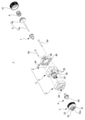
図1は、本発明の実施形態に係る自動スプレーガン1の斜視図であり、図2は、自動スプレーガン1の分解斜視図である。
図1及び図2に示すように、前端部2、中間部3及び後端部4からなるスプレーガン本体11と、前端部2に取付けられる気体キャップ5と、を備えている。中間部3は、前端部2と後端部4との間に設けられている。
図1及び図2に示すように、前端部2、中間部3及び後端部4からなるスプレーガン本体11と、前端部2に取付けられる気体キャップ5と、を備えている。中間部3は、前端部2と後端部4との間に設けられている。
また、図2に示すように、前端部2には、気体キャップ5が設けられるこの前端部2の前方側から中間部3に向かって貫通孔20が形成されている。
そして、中間部3には、前端部2の貫通孔20に挿入される突出部30が設けられている。自動スプレーガン1は、この突出部30に取付けられる液体ノズル6を備えている。
そして、中間部3には、前端部2の貫通孔20に挿入される突出部30が設けられている。自動スプレーガン1は、この突出部30に取付けられる液体ノズル6を備えている。
さらに、詳細な説明については後述するが、自動スプレーガン1は、中間部3に取付けられるシールカートリッジ7と、棒状の本体8aの後端にピストン8bが設けられたニードル8と、ピストン8bの後端側に配置され、ニードル8を前方側に付勢するコイルばねからなる弾性体9と、後端部4の後端側に設けられ、弾性体9のピストン8bと反対側になる端部を受ける蓋部10と、を備えている。
なお、本実施形態では、ニードル8の後端に設けられるピストン8bを別部品として、このピストン8bを棒状の本体8aに取付ける構成を示しているが、これに限定される必要はなく、ニードル8は、棒状の本体8aとピストン8bとを一体形成したものであっても良い。
なお、本実施形態では、ニードル8の後端に設けられるピストン8bを別部品として、このピストン8bを棒状の本体8aに取付ける構成を示しているが、これに限定される必要はなく、ニードル8は、棒状の本体8aとピストン8bとを一体形成したものであっても良い。
本実施形態の自動スプレーガン1は、塗装装置の取付部となるマニホールドに取付けられ、液体ノズル6から噴霧される液体やその噴霧される液体を微粒化する気体の供給を受けるマニホールド型の自動スプレーガンである。
なお、本実施形態の自動スプレーガン1は、塗料などの液体を塗装するのに好適に用いることができるものであるが、使用する液体は、塗料に限定される必要はなく、必要に応じて選択すればよい。
なお、本実施形態の自動スプレーガン1は、塗料などの液体を塗装するのに好適に用いることができるものであるが、使用する液体は、塗料に限定される必要はなく、必要に応じて選択すればよい。
具体的には、図2に示すように、気体キャップ5には、中心開口53が設けられている。この中心開口53内に、中心開口53との間に隙間を形成するように、液体ノズル6の先端60が配置される。この気体キャップ5の中心開口53と液体ノズル6の先端60とでスリット気体噴出口が形成される。そして、このスリット気体噴出口から噴出する気体によって、液体ノズル6から噴霧される液体が霧化液体の状態とされる。
また、気体キャップ5に設けられた一対の角51、52のそれぞれに設けられた気体噴出口51a、52a(図3参照)から噴出する気体によって、上述の霧化液体の噴霧形状が調整される。
例えば、気体噴出口51a、52aから噴出する気体の流量を少なくすると、噴霧される霧化液体の形状(噴霧パターン)は、円形に近づき、狭い範囲に液体を塗布するのに適した状態となる。
一方、気体噴出口51a、52aから噴出する気体の流量を増やすと、上述の円形の噴霧パターンが、気体噴出口51a、52aから噴出する気体によって偏平状にされ、長軸方向に噴霧パターンが広がった楕円形の状態になり、広い範囲に液体を塗布するのに適した状態となる。
なお、使用する気体としては、圧縮空気などを好適に用いることができるが、空気に限らず、窒素やアルゴン等のガスでもよく、必要に応じて適宜変更して良い。
なお、使用する気体としては、圧縮空気などを好適に用いることができるが、空気に限らず、窒素やアルゴン等のガスでもよく、必要に応じて適宜変更して良い。
以下、各部の組付け状態などを見ながら、スリット気体噴出口や気体噴出口51a、52aに供給される気体及び液体ノズル6に供給される液体などの供給経路等について詳細に説明する。
上述のように、本実施形態の自動スプレーガン1は、塗装装置のマニホールド(図示せず)に取付けられ、そのマニホールドから気体や液体の供給が行われるようになっている。自動スプレーガン1は、マニホールドに取り付けられる取付面を有している。気体や液体の供給口は、自動スプレーガン1のその取付面となる側に設けられている。
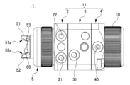
図3は、自動スプレーガンのマニホールドに取付けられる取付面を正面に見た平面図である。
図3に示すように、取付面側となる前端部2の面には、マニホールドからの気体の供給を受ける気体供給口が設けられている。
具体的には、気体キャップ5の角51、52に設けられる気体噴出口51a、52aに供給される気体を受け入れる角気体供給口21と、スリット気体噴出口に供給される気体を受け入れるスリット気体供給口22と、が設けられている。
図3に示すように、取付面側となる前端部2の面には、マニホールドからの気体の供給を受ける気体供給口が設けられている。
具体的には、気体キャップ5の角51、52に設けられる気体噴出口51a、52aに供給される気体を受け入れる角気体供給口21と、スリット気体噴出口に供給される気体を受け入れるスリット気体供給口22と、が設けられている。
また、取付面側となる中間部3の面には、液体ノズル6に供給される液体を受け入れる液体供給口31が設けられている。
さらに、取付面側となる後端部4の面には、液体ノズル6の先端開口に対するニードル8(棒状の本体8a)の先端の挿脱動作、つまり、液体ノズル6の開閉動作を行うために、ピストン8bを駆動させる気体を受け入れる動作気体供給口40が設けられている。
さらに、取付面側となる後端部4の面には、液体ノズル6の先端開口に対するニードル8(棒状の本体8a)の先端の挿脱動作、つまり、液体ノズル6の開閉動作を行うために、ピストン8bを駆動させる気体を受け入れる動作気体供給口40が設けられている。
(角への気体供給)
以下、図4及び図5を参照しながら、角51、52に設けられる気体噴出口51a、52aに供給される気体の供給経路について構成等を含め詳細に説明する。
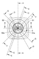
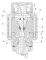
図4は自動スプレーガン1の気体キャップ5を正面に見た正面図であり、図5は図4のE-E線断面図である。
以下、図4及び図5を参照しながら、角51、52に設けられる気体噴出口51a、52aに供給される気体の供給経路について構成等を含め詳細に説明する。
図4は自動スプレーガン1の気体キャップ5を正面に見た正面図であり、図5は図4のE-E線断面図である。
なお、図5において、液体ノズル6の内部の液体が通る流路が無い図示になっているのは、角気体供給口21から供給される気体の供給路を図示するために、図5が、図4に示すE-E線に沿った斜めの断面図になっているためである。
上述したように、取付面側となる前端部2の面には、気体キャップ5の角51、52に設けられる気体噴出口51a、52aに供給される気体を受け入れる角気体供給口21が設けられている。
そして、図5に示すように、角気体供給口21は、角気体供給路12に連通している。角気体供給路12は、前端部2の貫通孔20の内周面20aと、中間部3の突出部30の外周面30aとの間の隙間によって形成されており、気体キャップ5の角51、52へ気体を供給する。
つまり、前端部2には、角気体供給口21から角気体供給路12(角気体供給路12の部分12a)に繋がる貫通孔が形成されている。
そして、図5に示すように、角気体供給口21は、角気体供給路12に連通している。角気体供給路12は、前端部2の貫通孔20の内周面20aと、中間部3の突出部30の外周面30aとの間の隙間によって形成されており、気体キャップ5の角51、52へ気体を供給する。
つまり、前端部2には、角気体供給口21から角気体供給路12(角気体供給路12の部分12a)に繋がる貫通孔が形成されている。
ここで、角気体供給口21が連通する角気体供給路12の部分12aは、周方向に延在する気体だまりとなる空間からなっている。角気体供給路12の部分12aは、前端部2の内周面20aが中間部3の突出部30の外周面30aから距離を取るように構成されている。
このため、角気体供給口21から供給された気体は、角気体供給口21が連通する部分12aに設けられた気体だまりとなる空間で周方向に均圧化され、その均圧化された気体が、角気体供給路12を通じて気体キャップ5側に供給されることになる。
このため、角気体供給口21から供給された気体は、角気体供給口21が連通する部分12aに設けられた気体だまりとなる空間で周方向に均圧化され、その均圧化された気体が、角気体供給路12を通じて気体キャップ5側に供給されることになる。
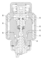
図6は、図4のB-B線断面図、つまり、角51、52の気体噴出口51a、52aを通る断面図になっている。
図6に示すように、角気体供給路12を流れる気体は、角51、52内の気体噴出口51a、52aに通じる気体流路51b、52bに供給されて気体噴出口51a、52aから噴出する。上述のように、角気体供給路12に供給される気体が、周方向に均圧化されるので、気体流路51b、52bに供給される気体の流量が均一化される。
このため、気体噴出口51a、52aから噴出する気体の流量も均一化される。
図6に示すように、角気体供給路12を流れる気体は、角51、52内の気体噴出口51a、52aに通じる気体流路51b、52bに供給されて気体噴出口51a、52aから噴出する。上述のように、角気体供給路12に供給される気体が、周方向に均圧化されるので、気体流路51b、52bに供給される気体の流量が均一化される。
このため、気体噴出口51a、52aから噴出する気体の流量も均一化される。
(スリット気体噴出口への気体供給)
次に、図4、図7及び図8を参照しながら、スリット気体噴出口13(図7参照)に供給される気体の供給経路について構成等を含め詳細に説明する。
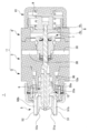
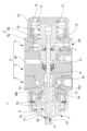
図7は図4のA-A線断面図であり、図8は図4のD-D線断面図である。
次に、図4、図7及び図8を参照しながら、スリット気体噴出口13(図7参照)に供給される気体の供給経路について構成等を含め詳細に説明する。
図7は図4のA-A線断面図であり、図8は図4のD-D線断面図である。
なお、先ほどと同様に、図8は、スリット気体供給口22から供給される気体の供給路を図示するために、図4に示すD-D線に沿った斜めの断面図となっている。
このため、液体ノズル6の内部の液体が通る流路6aが貫通していないような図になっているが、実際は、図7に示すように、液体ノズル6の先端60は、開口しており、その液体ノズル6の先端開口には、ニードル8(棒状の本体8a)の先端が、挿入されている。
このため、液体ノズル6の内部の液体が通る流路6aが貫通していないような図になっているが、実際は、図7に示すように、液体ノズル6の先端60は、開口しており、その液体ノズル6の先端開口には、ニードル8(棒状の本体8a)の先端が、挿入されている。
まず、図7に示すように、液体ノズル6には、液体ノズル6の液体が通る流路6aより外側の周囲に複数の気体流路6bが設けられている。気体流路6bの各々は、気体キャップ5の中心開口53と液体ノズル6の先端60とで形成されるスリット気体噴出口13に気体を供給するためものである。
そして、液体ノズル6の気体流路6bの後端側は、スリット気体用供給路14に繋がっているスリット気体用供給路14は、液体ノズル6の外周面61と中間部3の突出部30の内周面30bとの間の隙間として周方向に形成された気体だまりとなる空間である。
また、中間部3の突出部30には、スリット気体用供給路14に連通し突出部30の外周面30aに開口するスリット気体供給用孔32が設けられている。
また、中間部3の突出部30には、スリット気体用供給路14に連通し突出部30の外周面30aに開口するスリット気体供給用孔32が設けられている。
さらに、図8に示すように、前端部2の外側(取付面となる面)には、スリット気体供給口22が設けられている。スリット気体供給口22は、前端部2の内周面20aに開口している。一方、スリット気体供給用孔32が、中間部3に設けられている。スリット気体供給用孔32は、中間部3の突出部30の外周面30aに開口している。スリット気体供給口22は、スリット気体供給用孔32に対応する位置に設けられており、スリット気体供給口22はスリット気体供給用孔32に連通している。
つまり、前端部2には、スリット気体供給口22から、中間部3の突出部30の外周面30aに開口するスリット気体供給用孔32に対応する前端部2の内周面20aの箇所まで貫通する貫通孔が形成されている。
したがって、スリット気体供給口22に供給された気体は、気体だまりとなる空間であるスリット気体用供給路14のところで周方向に均圧化される。
つまり、前端部2には、スリット気体供給口22から、中間部3の突出部30の外周面30aに開口するスリット気体供給用孔32に対応する前端部2の内周面20aの箇所まで貫通する貫通孔が形成されている。
したがって、スリット気体供給口22に供給された気体は、気体だまりとなる空間であるスリット気体用供給路14のところで周方向に均圧化される。
そして、その周方向に均圧化された気体が、液体ノズル6の外周周囲に設けられた複数の気体流路6bを通じて、スリット気体噴出口13に供給される。上述のように、液体ノズル6の複数の気体流路6bに供給される気体が、周方向に均圧化されているので、液体ノズル6の複数の気体流路6bに供給される気体の流量が均一化される。
したがって、スリット気体噴出口13の手前の液体ノズル6と気体キャップ5とで形成される空間15には、液体ノズル6の複数の気体流路6bから流量のほぼ等しい気体が万遍なく供給される。
このため、この空間15内も均圧化されることとなり、スリット気体噴出口13から噴出する気体の噴出量が周方向で均一化されるので、液体の良好な噴霧状態と良好な微粒化が行える。
このため、この空間15内も均圧化されることとなり、スリット気体噴出口13から噴出する気体の噴出量が周方向で均一化されるので、液体の良好な噴霧状態と良好な微粒化が行える。
つまり、このスリット気体噴出口13から噴出する気体の噴出量が周方向で偏りがあると、液体ノズル6から噴出する液体は、その偏りに応じて噴霧方向に変位を来すことになる。この場合、きれいに前方側に噴霧する状態にならないだけでなく、気体の噴出量が多い側の液体は粒径が小さくなるとともに、気体の噴出量が少ない側の液体の粒径が大きくなり、噴霧される液体の粒径の均質性が低下する。
しかしながら、上述のように、スリット気体噴出口13の周方向で噴出する気体の噴出量が均一化されていれば、液体がきれいに前方側に噴霧されるとともに、その液体の粒径も均一化され、液体の良好な噴霧状態を得ることができる。
(液体ノズルへの液体供給)
次に、図4及び図4のC-C線断面図である図9を参照しながら、液体ノズル6に供給される液体の供給経路について構成等を含め詳細に説明する。
上述したように、取付面側となる中間部3の面には、液体ノズル6に供給される液体を受け入れる液体供給口31が設けられている。
次に、図4及び図4のC-C線断面図である図9を参照しながら、液体ノズル6に供給される液体の供給経路について構成等を含め詳細に説明する。
上述したように、取付面側となる中間部3の面には、液体ノズル6に供給される液体を受け入れる液体供給口31が設けられている。
そして、中間部3には、貫通孔34が設けられている。貫通孔34は、中間部3に設けられる液体供給口31に連通しており、前端部2側から後端部4側に向かって形成される突出部30を通っている。液体ノズル6は、突出部30の貫通孔34に取付けられている。
つまり、中間部3には、中間部3を前後方向に貫通する貫通孔34と、その貫通孔34と液体供給口31を繋ぐ貫通孔と、が形成されている。
つまり、中間部3には、中間部3を前後方向に貫通する貫通孔34と、その貫通孔34と液体供給口31を繋ぐ貫通孔と、が形成されている。
なお、液体ノズル6の取付けは、本実施形態の場合、以下のようになっている。中間部3の貫通孔34の前方側の部分34aの内周面に、雌ネジ構造が設けられている。液体ノズル6の後方側の部分64の外周面に雄ネジ構造が設けられている。雌ネジと雄ネジとの螺合接続によって、液体ノズル6が突出部30の貫通孔34に取付けられるようになっている。
また、液体ノズル6の後端65は、中間部3の突出部30の貫通孔34の内周面30bと接触して、液体ノズル6と突出部30との間がシールされるようになっている。
したがって、貫通孔34内を流れる液体は、液体ノズル6の液体が通る流路6aにだけ供給され、液体ノズル6の外周側に漏れないようになっている。
したがって、貫通孔34内を流れる液体は、液体ノズル6の液体が通る流路6aにだけ供給され、液体ノズル6の外周側に漏れないようになっている。
一方、貫通孔34は、中間部3の突出部30の手前の位置、つまり、液体供給口31が連通する部分の少し後方側の位置で、前方側及び後方側の双方から内径が小さくなり、ほぼニードル8(棒状の本体8a)の外径に近い内径となる狭窄部35となるようにされている。
そして、中間部3の貫通孔34に、後述するシールカートリッジ7が挿入されている。シールカートリッジ7は中間部3の後端部4側から中間部3の貫通孔34に挿入される。そして、シールカートリッジ7の先端が狭窄部35の後端側壁面に当接して、シールカートリッジ7は位置決めされる。
シールカートリッジ7の中央には、ニードル8(棒状の本体8a)を通すための貫通孔70が設けられている。中間部3にシールカートリッジ7を取付けた状態で、中間部3の後端部4側からニードル8の棒状の本体8aをシールカートリッジ7の貫通孔70を通す。そして、ニードル8の棒状の本体8aの先端を、液体ノズル6の先端60の先端開口に挿入するようにして、ニードル8が配置される。
シールカートリッジ7の中央には、ニードル8(棒状の本体8a)を通すための貫通孔70が設けられている。中間部3にシールカートリッジ7を取付けた状態で、中間部3の後端部4側からニードル8の棒状の本体8aをシールカートリッジ7の貫通孔70を通す。そして、ニードル8の棒状の本体8aの先端を、液体ノズル6の先端60の先端開口に挿入するようにして、ニードル8が配置される。
このように、中間部3の突出部30の貫通孔34に液体ノズル6を取付ける構成として、前端部2には液体が触れることがない構成としているので、従来の自動スプレーガンのように、前端部2を洗浄する必要はない。
また、中間部3の後端側にシールカートリッジ7を設けることで、後端部4も液体に触れることがないので後端部4を洗浄する必要もない構成になっており、液体に触れる部分が、全て中間部3に集約して設けられているため、洗浄が必要な部分は、中間部3及び中間部に集約された部材だけで良くなっている。
また、中間部3の後端側にシールカートリッジ7を設けることで、後端部4も液体に触れることがないので後端部4を洗浄する必要もない構成になっており、液体に触れる部分が、全て中間部3に集約して設けられているため、洗浄が必要な部分は、中間部3及び中間部に集約された部材だけで良くなっている。
さらに、中間部3に液体ノズル6、シールカートリッジ7を集約させることで液体ノズル6とシールカートリッジ7との軸精度(位置精度)を高めることができる。
つまり、例えば、液体ノズル6を前端部2に設け、シールカートリッジ7を中間部3に設けるようにした場合、液体ノズル6とシールカートリッジ7の中心軸が一致するようにするためには、前端部2における液体ノズル6の取付部の位置精度と中間部3におけるシールカートリッジ7の取付部の位置精度とを正確に管理するだけでなく、前端部2と中間部3との組付け精度までを正確に管理する必要がある。
つまり、例えば、液体ノズル6を前端部2に設け、シールカートリッジ7を中間部3に設けるようにした場合、液体ノズル6とシールカートリッジ7の中心軸が一致するようにするためには、前端部2における液体ノズル6の取付部の位置精度と中間部3におけるシールカートリッジ7の取付部の位置精度とを正確に管理するだけでなく、前端部2と中間部3との組付け精度までを正確に管理する必要がある。
しかしながら、本実施形態の場合、液体ノズル6もシールカートリッジ7も中間部3に設ける構成であるため、中間部3における液体ノズル6及びシールカートリッジ7の取付部の位置精度を正確に管理するだけでよい。
そして、ニードル8は、シールカートリッジ7の貫通孔70で位置決めがなされているため、液体ノズル6の先端60の先端開口に対して正確にニードル8(棒状の本体8a)の先端を位置させることが可能となる。
例えば、このニードル8(棒状の本体8a)の液体ノズル6の先端開口に対する位置精度が悪いと、ニードル8が後方側に移動し、液体ノズル6の先端開口が開放されるときに、ニードル8の先端が先端開口の中心と同軸を保ちながら前後方向に動かないことが起き、液体の噴出する開口状態に偏りが発生するので良好な液体の噴出状態にならない。
しかしながら、本実施形態の場合、液体ノズル6の先端開口に対するニードル8(棒状の本体8a)の先端の位置精度を高めることができるので、液体の噴出する開口状態に偏りが生じることを抑制することができ、良好な液体の噴出状態を得ることができる。
(ピストン駆動のための気体供給)
次に、図7を参照しながら、ピストン8bを駆動させる気体の供給経路の構成、及び、ピストン動作のための構成などについて詳細に説明する。
図7に示すように、後端部4には、ニードル8の後端に設けられるピストン8bを収容する開口42が設けられている。
次に、図7を参照しながら、ピストン8bを駆動させる気体の供給経路の構成、及び、ピストン動作のための構成などについて詳細に説明する。
図7に示すように、後端部4には、ニードル8の後端に設けられるピストン8bを収容する開口42が設けられている。
そして、ピストン8bの後端側には、ピストン8bを前方側に付勢するコイルばねからなる弾性体9が設けられている。また、ピストン8bと反対側になる弾性体9の端部を受ける蓋部10が、後端部4の後端側に設けられている。
このため、ピストン8bが駆動しない通常の状態のときには、この弾性体9によってピストン8bが前方側に付勢され、液体ノズル6の先端開口を塞ぐようにニードル8(棒状の本体8a)の先端が先端開口に挿入された状態となる。
このため、ピストン8bが駆動しない通常の状態のときには、この弾性体9によってピストン8bが前方側に付勢され、液体ノズル6の先端開口を塞ぐようにニードル8(棒状の本体8a)の先端が先端開口に挿入された状態となる。
一方、既に少し触れたように、取付面側となる後端部4の面には、中間部3とピストン8bとの間に連通する動作気体供給口40が設けられている。動作気体供給口40から、気体が、中間部3とピストン8bとの間に供給されて、ピストン8bを駆動できるようになっている。 つまり、後端部4には、動作気体供給口40から中間部3とピストン8bとの間の空間に繋がる貫通孔が設けられている。
したがって、動作気体供給口40から気体を供給すると、ピストン8bが弾性体9の付勢力に抗して後方側に移動し、それに伴い液体ノズル6の先端開口に挿入されているニードル8(棒状の本体8a)の先端も後方側に動き、液体ノズル6の先端開口が開口して、先端開口から液体が噴出する。
なお、このピストン8bの後方側への移動がスムーズに行えるように、蓋部10には、弾性体9の収納されている空間の空気が外に逃げることができる貫通孔18が設けられている。
なお、このピストン8bの後方側への移動がスムーズに行えるように、蓋部10には、弾性体9の収納されている空間の空気が外に逃げることができる貫通孔18が設けられている。
一方、液体の噴出を停止するときは、例えば、動作気体供給口40を通じて中間部3とピストン8bとの間の空間の気体を抜気するようにすれば良い。
このように抜気を行なえば、この空間の圧力が下がるのに応じて、再び、弾性体9の付勢力によってピストン8bが前方側に移動し、液体ノズル6の先端開口にニードル8(棒状の本体8a)の先端が挿入され、液体の噴出が停止する。
このように抜気を行なえば、この空間の圧力が下がるのに応じて、再び、弾性体9の付勢力によってピストン8bが前方側に移動し、液体ノズル6の先端開口にニードル8(棒状の本体8a)の先端が挿入され、液体の噴出が停止する。
ここで、シールカートリッジ7を見てみると、シールカートリッジ7の後端側には、動作気体供給口40から供給される気体が液体ノズル6側に向かうのをシールする気体シール部72が設けられている。シールカートリッジ7の前端側には、液体供給口31(図7には図示せず)から供給される液体が後端部4側に向かうのをシールする液体シール部73、74が設けられている。
そして、シールカートリッジ7は、これら気体シール部72及び液体シール部73、74を一体化したカートリッジになっており、コンパクト化ができる構成になっている。
そして、シールカートリッジ7は、これら気体シール部72及び液体シール部73、74を一体化したカートリッジになっており、コンパクト化ができる構成になっている。
また、気体シール部72のニードル8(棒状の本体8a)に接する側の端部(内径部側)は、ニードル8(棒状の本体8a)に沿って、後端部4側に曲げられており、気体が液体ノズル6側に向かう場合のシール性能を高めるようにしている。
一方、液体シール部73、74の先端は、気体シール部72と逆方向、つまり、ニードル8(棒状の本体8a)に沿って、前端部2側に曲げられており、液体が後端部4側に向かう場合のシール性能を高めるようにしている。
したがって、コンパクト化ができるとともに、高いシール性能が実現できるようにしている。
一方、液体シール部73、74の先端は、気体シール部72と逆方向、つまり、ニードル8(棒状の本体8a)に沿って、前端部2側に曲げられており、液体が後端部4側に向かう場合のシール性能を高めるようにしている。
したがって、コンパクト化ができるとともに、高いシール性能が実現できるようにしている。
ところで、長時間にわたってピストン駆動が繰り返されるような使用を長期間にわたって行うような使用形態の場合に、シールカートリッジ7でシールをしていても、液体が後端部4側に向かって若干漏れる場合がある。
そこで、本実施形態では、このシールカートリッジ7の部分を見ることができる検知孔38を中間部3に設けており、簡単に漏れを検知することが可能になっている。
そこで、本実施形態では、このシールカートリッジ7の部分を見ることができる検知孔38を中間部3に設けており、簡単に漏れを検知することが可能になっている。
なお、この検知孔38は、中間部3の3箇所に設けるようにしている。
具体的には、1つ目の検知孔38は、覗きやすさを考慮して、図7に示すように、自動スプレーガン1のマニホールドに取付けられる取付面と反対側の面、言い換えれば、液体供給口31が設けられる面と反対側になる面に開口するように形成されている。
残る2つの検知孔38は、図6に示すように、自動スプレーガン1のマニホールドに取付けられる取付面の横側のそれぞれの面に開口するように、1ずつ設けるようにしている。
このため、実際に検知孔38を覗こうとしたときに、仮に、塗装装置の周囲の状態が、液体供給口31が設けられる面と反対側になる面に設けられている1つ目の検知孔38を覗きにくいような状態であったとしても、残る2つの検知孔38の覗きやすい方の検知孔38から簡単に漏れの状態が確認できるようになっている。
具体的には、1つ目の検知孔38は、覗きやすさを考慮して、図7に示すように、自動スプレーガン1のマニホールドに取付けられる取付面と反対側の面、言い換えれば、液体供給口31が設けられる面と反対側になる面に開口するように形成されている。
残る2つの検知孔38は、図6に示すように、自動スプレーガン1のマニホールドに取付けられる取付面の横側のそれぞれの面に開口するように、1ずつ設けるようにしている。
このため、実際に検知孔38を覗こうとしたときに、仮に、塗装装置の周囲の状態が、液体供給口31が設けられる面と反対側になる面に設けられている1つ目の検知孔38を覗きにくいような状態であったとしても、残る2つの検知孔38の覗きやすい方の検知孔38から簡単に漏れの状態が確認できるようになっている。
次に、図2、図10及び図11を参照しながら、さらに、自動スプレーガン1の構成についての説明を行うとともに、自動スプレーガン1の組立て作業の一例を説明する。
図10は図4のF-F線断面図であり、図11は図4のG-G線断面図である。
図2に示すように、中間部3には、前端部2側の面の四隅から後端部4側の面の四隅までを貫通するピン孔39が設けられている。
そして、後端部4には、中間部3側の面の四隅のうち対角線上にある2つの隅に中間部3側に突出するピン49が設けられている。
図2に示すように、中間部3には、前端部2側の面の四隅から後端部4側の面の四隅までを貫通するピン孔39が設けられている。
そして、後端部4には、中間部3側の面の四隅のうち対角線上にある2つの隅に中間部3側に突出するピン49が設けられている。
また、図2では見えていないが、図11に示すように、前端部2にも中間部3側の面の四隅のうちの対角線上にある2つの隅に中間部3側に突出するピン29が設けられている。
なお、前端部2に設けられるピン29は、後端部4に設けられるピン49と対向する位置(同軸となる位置)に設けられている。
なお、前端部2に設けられるピン29は、後端部4に設けられるピン49と対向する位置(同軸となる位置)に設けられている。
したがって、前端部2、中間部3及び後端部4を組み合わせるときに、前端部2のピン29及び後端部4のピン49が中間部3のピン孔39に嵌合することで仮止めができるようになっている。
一方、図2に示すように、後端部4のピン49が設けられていない残る2つの隅には、中間部3側から後方まで貫通するピン孔48が設けられている。
また、図2では見えていないが、図10に示すように、前端部2にもピン29が設けられていない残る2つの隅には、有底状のピン孔28が設けられている。
また、図2では見えていないが、図10に示すように、前端部2にもピン29が設けられていない残る2つの隅には、有底状のピン孔28が設けられている。
したがって、前端部2、中間部3、及び、後端部4を一体化するための連結ピン99を後端部4の方向側から前端部2側に向かって挿入することで、前端部2、中間部3、及び、後端部4が連結一体化するようになっている。
以上のような構成からなる自動スプレーガン1の具体的な組立て手順の一例を図2、図10及び図11を参照しながら以下に説明する。
先ず、中間部3の突出部30を前端部2の貫通孔20に挿入するとともに、中間部3のピン孔39に前端部2のピン29を嵌合させるようにして前端部2と中間部3とを組付ける。
先ず、中間部3の突出部30を前端部2の貫通孔20に挿入するとともに、中間部3のピン孔39に前端部2のピン29を嵌合させるようにして前端部2と中間部3とを組付ける。
ここで、図10及び図11を見るとわかるように、中間部3の突出部30は、前端部2側に向かって外径が小さくなるテーパ部を有するように形成されており、また、前端部2の貫通孔20は、中間部3に向かって内径が大きくなるテーパ部を有するようになっている(図10の範囲W参照)。
そして、前端部2の貫通孔20のテーパ部と中間部3の突出部30のテーパ部とが合わさることで、前端部2と中間部3との組付け時の位置合わせが、正確に行えるようになっている。
このようにテーパ状の孔とテーパ状の凸部とを嵌合させる構造の場合、ほとんどガタを許す必要が無いので、前端部2の貫通孔20と中間部3の突出部30にテーパ部を設けた構造とすることで、ガタなく正確に組付けられることになる。
図2に戻って説明を続ける。次に、中間部3の突出部30の貫通孔34に、既に説明したように、液体ノズル6を螺合接続する。
続いて、中間部3の貫通孔34に後端側から挿入するようにしてシールカートリッジ7を取付ける。
そして、シールカートリッジ7の取付けが終った後、中間部3のピン孔39に後端部4のピン49を嵌合するようにして後端部4の組付けを行う。
続いて、中間部3の貫通孔34に後端側から挿入するようにしてシールカートリッジ7を取付ける。
そして、シールカートリッジ7の取付けが終った後、中間部3のピン孔39に後端部4のピン49を嵌合するようにして後端部4の組付けを行う。
ここで、図10に示すように、中間部3の後端部4側には、後端部4側に向かって外径が小さくなるテーパ部95が設けられており、後端部4の中間部3側には、テーパ部95を受け入れる中間部3の後端側に向かって内径が大きくなるテーパ部96が設けられている。
したがって、中間部3と後端部4との組付けにおいても、中間部3の後端部4側に向かって外径が小さくなるテーパ部95と後端部4の中間部3側に向かって内径が大きくなるテーパ部96とで、中間部3と後端部4との組付け時の正確な位置合わせができるようになっている。
このように、前端部2、中間部3、及び、後端部4の組付けが終わると、これらを連結ピン99で連結一体化し、その後、後端部4の後端側から順次、ニードル8、弾性体9を組付けて蓋部10を後端部4に取付けるようにする。
なお、前端部2の有底状のピン孔28の内周面には、雌ネジ構造が設けられ、連結ピン99の先端側には、雄ネジ構造が設けられており、連結一体化はピン孔28の雌ネジ構造に連結ピン99の雄ネジ構造を螺合することで行われる。
最後に、気体キャップ5を前端部2に取付ければ、自動スプレーガン1の組立てが終了する。
なお、上記組立て手順は単なる一例であるから、異なる順番で組立を行っても良い。
なお、前端部2の有底状のピン孔28の内周面には、雌ネジ構造が設けられ、連結ピン99の先端側には、雄ネジ構造が設けられており、連結一体化はピン孔28の雌ネジ構造に連結ピン99の雄ネジ構造を螺合することで行われる。
最後に、気体キャップ5を前端部2に取付ければ、自動スプレーガン1の組立てが終了する。
なお、上記組立て手順は単なる一例であるから、異なる順番で組立を行っても良い。
ここで、上述したように、本実施形態では、前端部2と中間部3とは、ガタなく正確な組付けが可能となっている。
このため、前端部2に取付けられる気体キャップ5も、液体ノズル6に対して正確に所定の位置にさせることができるので、例えば、気体キャップ5の中心開口53が液体ノズル6の先端60に対してオフセットしたりすることがなく、周方向に均一なスリット幅のスリット気体噴出口13を形成できるようになり、噴霧される液体の噴霧パターンをより良好な噴霧パターンにすることができる。
このため、前端部2に取付けられる気体キャップ5も、液体ノズル6に対して正確に所定の位置にさせることができるので、例えば、気体キャップ5の中心開口53が液体ノズル6の先端60に対してオフセットしたりすることがなく、周方向に均一なスリット幅のスリット気体噴出口13を形成できるようになり、噴霧される液体の噴霧パターンをより良好な噴霧パターンにすることができる。
以上、具体的な実施形態に基づいて本発明を説明してきたが、本発明は上記実施形態に限定されるものではなく、適宜、変形や改良を実施しても良く、そのような変形や改良を施したものも本発明の技術的範囲に含まれることは、当業者にとって特許請求の範囲の記載から明らかである。上記実施形態を任意に組み合わせても良い。
本願は、2015年4月9日付出願の日本国特許出願第2015-79682号に基づく優先権を主張する。2015年4月9日付出願の日本国特許出願第2015-79682号の明細書、特許請求の範囲、図面、及び要約書を含む全開示内容は、参照により本願に全体として組み込まれる。
1 自動スプレーガン
2 前端部
3 中間部
4 後端部
5 気体キャップ
6 液体ノズル
6a 液体が通る流路
6b 気体流路
7 シールカートリッジ
8 ニードル
8a 棒状の本体
8b ピストン
9 弾性体
10 蓋部
11 スプレーガン本体
12 角気体供給路
12a 部分
13 スリット気体噴出口
14 スリット気体用供給路
15 空間
20 貫通孔
20a 内周面
21 角気体供給口
22 スリット気体供給口
28 有底状のピン孔
29 ピン
30 突出部
30a 外周面
30b 内周面
31 液体供給口
32 スリット気体供給用孔
34 貫通孔
34a 前方側の部分
35 狭窄部
38 検知孔
39 ピン孔
40 動作気体供給口
48 ピン孔
49 ピン
51、52 角
51a、52a 気体噴出口
53 中心開口
60 先端
61 外周面
64 後方側の部分
65 後端
70 貫通孔
72 気体シール部
73、74 液体シール部
95 テーパ部
96 テーパ部
99 連結ピン
2 前端部
3 中間部
4 後端部
5 気体キャップ
6 液体ノズル
6a 液体が通る流路
6b 気体流路
7 シールカートリッジ
8 ニードル
8a 棒状の本体
8b ピストン
9 弾性体
10 蓋部
11 スプレーガン本体
12 角気体供給路
12a 部分
13 スリット気体噴出口
14 スリット気体用供給路
15 空間
20 貫通孔
20a 内周面
21 角気体供給口
22 スリット気体供給口
28 有底状のピン孔
29 ピン
30 突出部
30a 外周面
30b 内周面
31 液体供給口
32 スリット気体供給用孔
34 貫通孔
34a 前方側の部分
35 狭窄部
38 検知孔
39 ピン孔
40 動作気体供給口
48 ピン孔
49 ピン
51、52 角
51a、52a 気体噴出口
53 中心開口
60 先端
61 外周面
64 後方側の部分
65 後端
70 貫通孔
72 気体シール部
73、74 液体シール部
95 テーパ部
96 テーパ部
99 連結ピン
Claims (7)
- 自動スプレーガンであって、
前端部と、後端部、前記前端部と前記後端部との間に設けられた中間部とを有するスプレーガン本体と、
前記前端部に取付けられる気体キャップと、
前記中間部に取付けられる液体ノズルと、
前記液体ノズルの開閉を行うニードルと、を備え、
前記前端部には、前記気体キャップが設けられる該前端部の前方側から前記中間部に向かって貫通孔が形成され、
前記中間部には、
前記前端部の前記貫通孔に挿入される突出部と、
前記中間部に設けられる液体供給口に連通し、前記前端部側から前記後端部側に向かって形成される前記突出部を通る貫通孔と、が設けられ、
前記液体ノズルが、前記突出部の前記貫通孔に取付けられ、
前記ニードルは前記後端部から前記中間部の前記貫通孔を通って延在しており、前記ニードルの先端が前記液体ノズルの先端開口に挿脱可能に挿入されていることを特徴とする自動スプレーガン。 - 請求項1に記載の自動スプレーガンにおいて、
前記前端部には、
前記気体キャップの角に設けられる気体噴出口に供給される気体を受け入れる角気体供給口が設けられ、
前記角気体供給口は、前記前端部の前記貫通孔の内周面と前記突出部の外周面との間の隙間によって形成される角気体供給路であって、前記気体キャップの角へ前記気体を供給する前記角気体供給路に連通しており、
前記角気体供給口が連通する前記角気体供給路は、その部分に、周方向に前記前端部の前記内周面が前記突出部の外周面から距離を取るようにして気体だまりとなる空間を備えていることを特徴とする自動スプレーガン。 - 請求項1または請求項2に記載の自動スプレーガンにおいて、
前記液体ノズルの液体が通る流路より外側の周囲に、複数の気体流路が設けられており、前記気体流路の各々を介して、気体が、前記気体キャップの中心開口と前記液体ノズルの先端とで形成されるスリット気体噴出口に供給されており、
前記液体ノズルの前記気体流路の後端側は、前記液体ノズルの外周面と前記突出部の内周面との間の隙間として周方向に形成された気体だまりとなる空間であるスリット気体用供給路に繋がっており、
前記突出部には、前記スリット気体用供給路に連通し前記突出部の外周面に開口するスリット気体供給用孔が設けられており、
前記スリット気体供給用孔は、前記突出部の外周面に開口しており、前記前端部には、スリット気体供給口が設けられており、該スリット気体供給口は前記前端部の内周面に開口しており、前記スリット気体供給口は、前記スリット気体供給用孔に対応する位置に設けられて、該スリット気体供給用孔に連通することを特徴とする自動スプレーガン。 - 請求項1から請求項3のいずれか1項に記載の自動スプレーガンにおいて、
前記前端部の前記貫通孔は、前記中間部に向かって内径が大きくなるテーパ部を有し、
前記中間部の前記突出部は、前記前端部に向かって外径が小さくなるテーパ部を有し、
前記前端部の前記貫通孔の前記テーパ部と前記中間部の前記突出部の前記テーパ部とで、前記前端部と前記中間部との組付け時の位置合わせができることを特徴とする自動スプレーガン。 - 請求項1から請求項4のいずれか1項に記載の自動スプレーガンにおいて、
前記中間部には、前記後端部側に設けられた前記後端部側に向かって外径が小さくなるテーパ部が設けられ、
前記後端部には、前記中間部の前記後端部側に向かって外径が小さくなるテーパ部を受け入れる、前記中間部側に向かって内径が大きくなるテーパ部が設けられ、
前記中間部の前記後端部側に向かって外径が小さくなるテーパ部と前記後端部の前記中間部側に向かって内径が大きくなるテーパ部とで、前記中間部と前記後端部との組付け時の位置合わせができることを特徴とする自動スプレーガン。 - 請求項1から請求項5のいずれか1項に記載の自動スプレーガンにおいて、
前記自動スプレーガンは、さらに、
前記ニードルの後端に設けられるピストンと、
前記ピストンの後端側に配置され、前記ピストンを前方側に付勢する弾性体と、
前記後端部の後端側に設けられ、前記ピストンと反対側になる前記弾性体の端部を受けるに蓋部と、を備え、
前記後端部には、
前記ピストンを収納する開口と、
前記ピストンを駆動するために、前記中間部と前記ピストンとの間の空間に供給される気体を受け入れる、前記中間部と前記ピストンとの間の前記空間に連通する動作気体供給口と、が設けられていることを特徴とする自動スプレーガン。 - 請求項6に記載の自動スプレーガンにおいて、
前記自動スプレーガンは、さらに、
前記中間部の前記貫通孔に前記後端部側から挿入され、前記動作気体供給口から供給される気体が前記液体ノズル側に向かうのをシールする気体シール部と、前記液体供給口から供給される液体が前記後端部側に向かうのをシールする液体シール部とを一体化したシールカートリッジを備え、
前記ニードルは前記シールカートリッジの貫通孔及び前記中間部の前記貫通孔を通って、前記ニードルの先端が前記液体ノズルの先端開口に挿脱可能に挿入されていることを特徴とする自動スプレーガン。
Priority Applications (3)
| Application Number | Priority Date | Filing Date | Title |
|---|---|---|---|
| EP16776479.4A EP3281707A4 (en) | 2015-04-09 | 2016-04-01 | Automatic spray gun |
| CN201680019680.9A CN107427853A (zh) | 2015-04-09 | 2016-04-01 | 自动喷枪 |
| US15/564,610 US20180071758A1 (en) | 2015-04-09 | 2016-04-01 | Automatic spray gun |
Applications Claiming Priority (2)
| Application Number | Priority Date | Filing Date | Title |
|---|---|---|---|
| JP2015-079682 | 2015-04-09 | ||
| JP2015079682A JP6531939B2 (ja) | 2015-04-09 | 2015-04-09 | 自動スプレーガン |
Publications (1)
| Publication Number | Publication Date |
|---|---|
| WO2016163313A1 true WO2016163313A1 (ja) | 2016-10-13 |
Family
ID=57072501
Family Applications (1)
| Application Number | Title | Priority Date | Filing Date |
|---|---|---|---|
| PCT/JP2016/060880 Ceased WO2016163313A1 (ja) | 2015-04-09 | 2016-04-01 | 自動スプレーガン |
Country Status (5)
| Country | Link |
|---|---|
| US (1) | US20180071758A1 (ja) |
| EP (1) | EP3281707A4 (ja) |
| JP (1) | JP6531939B2 (ja) |
| CN (1) | CN107427853A (ja) |
| WO (1) | WO2016163313A1 (ja) |
Families Citing this family (5)
| Publication number | Priority date | Publication date | Assignee | Title |
|---|---|---|---|---|
| KR101887209B1 (ko) * | 2017-02-08 | 2018-08-09 | (주)디유티코리아 | 섬유강화 복합재료 수지 주입용 믹싱헤드 |
| JP7150576B2 (ja) * | 2018-11-26 | 2022-10-11 | タクボエンジニアリング株式会社 | 塗料充填ユニット及びそれを備えた塗料充填装置 |
| CN111515045A (zh) * | 2020-05-15 | 2020-08-11 | 扬州荣德新能源科技有限公司 | 一种适用铸造单晶喷涂机器人喷枪安装方法 |
| CN111940164B (zh) * | 2020-08-20 | 2021-09-14 | 广东博智林机器人有限公司 | 自动喷枪、喷涂设备及喷涂设备的喷涂控制方法 |
| US12208407B2 (en) | 2021-03-05 | 2025-01-28 | Graco Minnesota Inc. | Alignment tool for a spray gun air cap |
Citations (3)
| Publication number | Priority date | Publication date | Assignee | Title |
|---|---|---|---|---|
| JPH03114559A (ja) * | 1989-08-04 | 1991-05-15 | Devilbiss Gmbh | スプレーガン |
| JP2006521205A (ja) * | 2003-03-27 | 2006-09-21 | スプレイング システムズ カンパニー | 複数の制御モジュールを有するモジュール式スプレーガン |
| JP2007021459A (ja) * | 2005-07-21 | 2007-02-01 | Meiji Kikai Seisakusho:Kk | 自動スプレーガン |
Family Cites Families (12)
| Publication number | Priority date | Publication date | Assignee | Title |
|---|---|---|---|---|
| US6520426B2 (en) * | 2000-01-26 | 2003-02-18 | Spraying Systems Co. | Sanitary spray nozzle for spray guns |
| WO2004035222A2 (en) * | 2002-10-15 | 2004-04-29 | Spraying Systems, Co. | External mix air assisted spray nozzle assembly |
| US6935577B2 (en) * | 2003-02-28 | 2005-08-30 | Illinois Tool Works Inc. | One-piece fluid nozzle |
| US7070066B2 (en) * | 2004-04-08 | 2006-07-04 | Nordson Corporation | Liquid dispensing valve and method with improved stroke length calibration and fluid fittings |
| FR2872717B1 (fr) * | 2004-07-12 | 2006-09-15 | Itw Surfaces & Finitions Sa | Pistolet de pulverisation automatique comprenant un corps de pulverisation monte sur une embase d'alimentation |
| TWM275032U (en) * | 2004-07-23 | 2005-09-11 | Chia Chung Prec Ind Co Ltd | Head structure of jetting gun |
| GB0609434D0 (en) * | 2006-05-12 | 2006-06-21 | Delavan Ltd | Spray nozzle |
| FR2903027B1 (fr) * | 2006-07-03 | 2008-11-14 | Exel Ind Sa | Pistolet automatique de pulverisation |
| EP2108460A4 (en) * | 2007-01-30 | 2011-05-18 | Shunji Noshima | GUN |
| JP5412668B2 (ja) * | 2009-02-09 | 2014-02-12 | ランズバーグ・インダストリー株式会社 | 調整部材を備えたスプレー装置 |
| WO2011049081A1 (ja) * | 2009-10-20 | 2011-04-28 | フロイント産業株式会社 | スプレーガン |
| WO2011133342A1 (en) * | 2010-04-19 | 2011-10-27 | Spraying Systems Co. | External mix air assisted spray nozzle assembly |
-
2015
- 2015-04-09 JP JP2015079682A patent/JP6531939B2/ja active Active
-
2016
- 2016-04-01 CN CN201680019680.9A patent/CN107427853A/zh active Pending
- 2016-04-01 US US15/564,610 patent/US20180071758A1/en not_active Abandoned
- 2016-04-01 EP EP16776479.4A patent/EP3281707A4/en not_active Withdrawn
- 2016-04-01 WO PCT/JP2016/060880 patent/WO2016163313A1/ja not_active Ceased
Patent Citations (3)
| Publication number | Priority date | Publication date | Assignee | Title |
|---|---|---|---|---|
| JPH03114559A (ja) * | 1989-08-04 | 1991-05-15 | Devilbiss Gmbh | スプレーガン |
| JP2006521205A (ja) * | 2003-03-27 | 2006-09-21 | スプレイング システムズ カンパニー | 複数の制御モジュールを有するモジュール式スプレーガン |
| JP2007021459A (ja) * | 2005-07-21 | 2007-02-01 | Meiji Kikai Seisakusho:Kk | 自動スプレーガン |
Non-Patent Citations (1)
| Title |
|---|
| See also references of EP3281707A4 * |
Also Published As
| Publication number | Publication date |
|---|---|
| EP3281707A1 (en) | 2018-02-14 |
| JP2016198708A (ja) | 2016-12-01 |
| JP6531939B2 (ja) | 2019-06-19 |
| US20180071758A1 (en) | 2018-03-15 |
| CN107427853A (zh) | 2017-12-01 |
| EP3281707A4 (en) | 2018-11-21 |
Similar Documents
| Publication | Publication Date | Title |
|---|---|---|
| JP6531939B2 (ja) | 自動スプレーガン | |
| JP6538661B2 (ja) | ノズルアセンブリ、システム、及び関連方法 | |
| EP3797873B1 (en) | Spray head assembly with integrated air cap/nozzle for a liquid spray gun | |
| JP5819994B2 (ja) | 塗料カートリッジ付スプレイガン | |
| CN110787925A (zh) | 喷枪基体、喷枪、喷枪套装、制造基体和改装喷枪方法 | |
| CN110787926A (zh) | 喷枪的喷嘴、喷嘴组件、喷枪和制造喷枪的喷嘴的方法 | |
| JP5654834B2 (ja) | スプレーガン、塗装システム | |
| JP5635148B2 (ja) | ノズル切替え弁 | |
| US4976467A (en) | Liquid spraying nozzle | |
| JP5946597B1 (ja) | 噴霧ノズル装置 | |
| CN111940164B (zh) | 自动喷枪、喷涂设备及喷涂设备的喷涂控制方法 | |
| KR20180014108A (ko) | Pcb 기판의 컨포멀 코팅용 스프레이 건 | |
| WO2018230589A1 (ja) | スプレーガン | |
| JP2014125058A (ja) | 車輌用洗浄装置 | |
| CN217120594U (zh) | 一种手持式喷枪 | |
| JP2008023465A (ja) | スプレーガン | |
| JP7822319B2 (ja) | 塗布剤切替器の塗布剤主チャネルへの接続のためのリンス装置 | |
| CN217120595U (zh) | 一种喷枪 | |
| KR101605043B1 (ko) | 분사장치 및 이를 구비하는 분사용기 | |
| KR200295531Y1 (ko) | 고체적 저압 스프레이건 | |
| WO2012127647A1 (ja) | ノズルの先端部材及びそれを用いたノズル | |
| JP6209102B2 (ja) | 先端カバー及びそれを取付けた静電塗装機 | |
| JP2003024838A (ja) | 塗装ガン | |
| JPH1147645A (ja) | エアー併用型エアレスガン | |
| JP2006055736A (ja) | 液体循環式スプレーガン |
Legal Events
| Date | Code | Title | Description |
|---|---|---|---|
| 121 | Ep: the epo has been informed by wipo that ep was designated in this application |
Ref document number: 16776479 Country of ref document: EP Kind code of ref document: A1 |
|
| WWE | Wipo information: entry into national phase |
Ref document number: 15564610 Country of ref document: US |
|
| NENP | Non-entry into the national phase |
Ref country code: DE |