WO2016163408A1 - Procédé de traitement de lame, dispositif de traitement de lame, et programme de commande d'instruction de traitement pour ledit dispositif de traitement - Google Patents
Procédé de traitement de lame, dispositif de traitement de lame, et programme de commande d'instruction de traitement pour ledit dispositif de traitement Download PDFInfo
- Publication number
- WO2016163408A1 WO2016163408A1 PCT/JP2016/061285 JP2016061285W WO2016163408A1 WO 2016163408 A1 WO2016163408 A1 WO 2016163408A1 JP 2016061285 W JP2016061285 W JP 2016061285W WO 2016163408 A1 WO2016163408 A1 WO 2016163408A1
- Authority
- WO
- WIPO (PCT)
- Prior art keywords
- tool
- gripping
- processing
- blade
- workpiece
- Prior art date
- Legal status (The legal status is an assumption and is not a legal conclusion. Google has not performed a legal analysis and makes no representation as to the accuracy of the status listed.)
- Ceased
Links
Images




Classifications
-
- B—PERFORMING OPERATIONS; TRANSPORTING
- B23—MACHINE TOOLS; METAL-WORKING NOT OTHERWISE PROVIDED FOR
- B23C—MILLING
- B23C3/00—Milling particular work; Special milling operations; Machines therefor
- B23C3/16—Working surfaces curved in two directions
- B23C3/18—Working surfaces curved in two directions for shaping screw-propellers, turbine blades, or impellers
-
- B—PERFORMING OPERATIONS; TRANSPORTING
- B23—MACHINE TOOLS; METAL-WORKING NOT OTHERWISE PROVIDED FOR
- B23Q—DETAILS, COMPONENTS, OR ACCESSORIES FOR MACHINE TOOLS, e.g. ARRANGEMENTS FOR COPYING OR CONTROLLING; MACHINE TOOLS IN GENERAL CHARACTERISED BY THE CONSTRUCTION OF PARTICULAR DETAILS OR COMPONENTS; COMBINATIONS OR ASSOCIATIONS OF METAL-WORKING MACHINES, NOT DIRECTED TO A PARTICULAR RESULT
- B23Q3/00—Devices holding, supporting, or positioning work or tools, of a kind normally removable from the machine
- B23Q3/02—Devices holding, supporting, or positioning work or tools, of a kind normally removable from the machine for mounting on a work-table, tool-slide, or analogous part
- B23Q3/06—Work-clamping means
- B23Q3/062—Work-clamping means adapted for holding workpieces having a special form or being made from a special material
- B23Q3/063—Work-clamping means adapted for holding workpieces having a special form or being made from a special material for holding turbine blades
-
- B—PERFORMING OPERATIONS; TRANSPORTING
- B23—MACHINE TOOLS; METAL-WORKING NOT OTHERWISE PROVIDED FOR
- B23Q—DETAILS, COMPONENTS, OR ACCESSORIES FOR MACHINE TOOLS, e.g. ARRANGEMENTS FOR COPYING OR CONTROLLING; MACHINE TOOLS IN GENERAL CHARACTERISED BY THE CONSTRUCTION OF PARTICULAR DETAILS OR COMPONENTS; COMBINATIONS OR ASSOCIATIONS OF METAL-WORKING MACHINES, NOT DIRECTED TO A PARTICULAR RESULT
- B23Q3/00—Devices holding, supporting, or positioning work or tools, of a kind normally removable from the machine
- B23Q3/02—Devices holding, supporting, or positioning work or tools, of a kind normally removable from the machine for mounting on a work-table, tool-slide, or analogous part
-
- B—PERFORMING OPERATIONS; TRANSPORTING
- B23—MACHINE TOOLS; METAL-WORKING NOT OTHERWISE PROVIDED FOR
- B23Q—DETAILS, COMPONENTS, OR ACCESSORIES FOR MACHINE TOOLS, e.g. ARRANGEMENTS FOR COPYING OR CONTROLLING; MACHINE TOOLS IN GENERAL CHARACTERISED BY THE CONSTRUCTION OF PARTICULAR DETAILS OR COMPONENTS; COMBINATIONS OR ASSOCIATIONS OF METAL-WORKING MACHINES, NOT DIRECTED TO A PARTICULAR RESULT
- B23Q3/00—Devices holding, supporting, or positioning work or tools, of a kind normally removable from the machine
- B23Q3/02—Devices holding, supporting, or positioning work or tools, of a kind normally removable from the machine for mounting on a work-table, tool-slide, or analogous part
- B23Q3/10—Auxiliary devices, e.g. bolsters, extension members
-
- F—MECHANICAL ENGINEERING; LIGHTING; HEATING; WEAPONS; BLASTING
- F01—MACHINES OR ENGINES IN GENERAL; ENGINE PLANTS IN GENERAL; STEAM ENGINES
- F01D—NON-POSITIVE DISPLACEMENT MACHINES OR ENGINES, e.g. STEAM TURBINES
- F01D25/00—Component parts, details, or accessories, not provided for in, or of interest apart from, other groups
-
- F—MECHANICAL ENGINEERING; LIGHTING; HEATING; WEAPONS; BLASTING
- F02—COMBUSTION ENGINES; HOT-GAS OR COMBUSTION-PRODUCT ENGINE PLANTS
- F02C—GAS-TURBINE PLANTS; AIR INTAKES FOR JET-PROPULSION PLANTS; CONTROLLING FUEL SUPPLY IN AIR-BREATHING JET-PROPULSION PLANTS
- F02C7/00—Features, components parts, details or accessories, not provided for in, or of interest apart form groups F02C1/00 - F02C6/00; Air intakes for jet-propulsion plants
-
- F—MECHANICAL ENGINEERING; LIGHTING; HEATING; WEAPONS; BLASTING
- F04—POSITIVE - DISPLACEMENT MACHINES FOR LIQUIDS; PUMPS FOR LIQUIDS OR ELASTIC FLUIDS
- F04D—NON-POSITIVE-DISPLACEMENT PUMPS
- F04D29/00—Details, component parts, or accessories
- F04D29/26—Rotors specially for elastic fluids
- F04D29/32—Rotors specially for elastic fluids for axial flow pumps
- F04D29/38—Blades
-
- F—MECHANICAL ENGINEERING; LIGHTING; HEATING; WEAPONS; BLASTING
- F04—POSITIVE - DISPLACEMENT MACHINES FOR LIQUIDS; PUMPS FOR LIQUIDS OR ELASTIC FLUIDS
- F04D—NON-POSITIVE-DISPLACEMENT PUMPS
- F04D29/00—Details, component parts, or accessories
- F04D29/60—Mounting; Assembling; Disassembling
-
- B—PERFORMING OPERATIONS; TRANSPORTING
- B23—MACHINE TOOLS; METAL-WORKING NOT OTHERWISE PROVIDED FOR
- B23C—MILLING
- B23C2215/00—Details of workpieces
- B23C2215/44—Turbine blades
-
- B—PERFORMING OPERATIONS; TRANSPORTING
- B23—MACHINE TOOLS; METAL-WORKING NOT OTHERWISE PROVIDED FOR
- B23Q—DETAILS, COMPONENTS, OR ACCESSORIES FOR MACHINE TOOLS, e.g. ARRANGEMENTS FOR COPYING OR CONTROLLING; MACHINE TOOLS IN GENERAL CHARACTERISED BY THE CONSTRUCTION OF PARTICULAR DETAILS OR COMPONENTS; COMBINATIONS OR ASSOCIATIONS OF METAL-WORKING MACHINES, NOT DIRECTED TO A PARTICULAR RESULT
- B23Q2230/00—Special operations in a machine tool
- B23Q2230/006—Machining both ends of a workpiece consecutively
Definitions
- the present invention relates to a blade processing method having a wing portion that is long in one direction and a mounting portion provided at one end of the wing portion, a processing device for the blade, and a processing sequence control program for the processing device. .
- This application claims priority based on Japanese Patent Application No. 2015-079366 for which it applied to Japan on April 8, 2015, and uses the content here.
- a moving blade such as a compressor has a wing portion extending in one direction and a mounting portion provided at one end of the wing portion.
- Patent Document 1 it is necessary to form a fixing portion that does not constitute a blade in the process of processing the blade from the material, and there is a problem that the manufacturing lead time of the blade is increased.
- an object of the present invention is to provide a technique capable of shortening the manufacturing lead time.
- the method for processing a wing as a first aspect according to the invention for solving the above problems is as follows.
- a blade processing method having a blade portion that is long in one direction and a mounting portion provided at an end of the blade portion in one direction, a base, a plurality of workpiece gripping machines that grip a workpiece, and the plurality of workpieces
- a gripping movement mechanism that is provided on the base for each workpiece gripper and changes the orientation and position of the workpiece gripper, and one or more tool drive mechanisms that are mounted with a processing tool for processing a processing target and drive the processing tool
- a tool moving mechanism provided on the base for each of the one or more tool driving mechanisms, and changing a direction and a position of at least a portion on which the processing tool is mounted by the tool driving mechanism
- a first gripping step in which a first workpiece gripper among a plurality of workpiece grippers grips a blade forming portion that becomes the blade portion in a material, and any one of the one or more tool drive mechanisms.
- An attachment portion that drives the tool moving mechanism relative to the tool drive mechanism to process an attachment forming portion that becomes the attachment portion in the material that is gripped by the first workpiece gripper to form the attachment portion.
- a second gripping step of causing the second workpiece gripping machine of the plurality of workpiece gripping machines to grip the mounting portion after the processing step and the mounting portion processing step; and after the second gripping step, the first workpiece
- a first grip release step for releasing gripping of the blade forming part by a gripper, and after the first grip release step, the tool drive mechanism and the tool drive mechanism among the one or more tool drive mechanisms
- a wing part machining step of driving the tool moving mechanism to form the wing part by processing the wing forming part in the material gripped by the second workpiece gripping machine.
- the attachment forming portion in the material is processed to form the attachment portion in a state where the blade forming portion in the material is gripped by the first workpiece gripping machine. Thereafter, in a state where the attachment portion is gripped by the second workpiece gripping machine, the blade forming portion is processed to form the blade portion.
- the blades can be processed consistently with a single processing device by transferring the material from the first work gripper to the second work gripper. For this reason, in the said processing method, it is not necessary to transfer a raw material to a several processing apparatus in the process of forming a wing
- the manufacturing lead time of the wing can be shortened.
- the blades can be processed consistently with a single processing device, so the load of quality control of the processed blades can be reduced.
- the method of processing a wing as the second aspect according to the invention for solving the above problems is as follows.
- the blade processing method according to the first aspect in the state in which the one direction of the material on which the attachment portion is gripped by the second workpiece gripping machine is oriented in a direction including a horizontal component, the blade portion A processing step is executed, and during the execution of the blade processing step, the blade forming portion is supported by a support tool from the lower side of the blade forming portion in the material in which the attachment portion is gripped by the second workpiece gripping machine.
- a supporting step is performed.
- the mounting portion in the material is gripped by the second workpiece gripping machine, and the blade forming portion of the material is supported from below by the support tool, and the blade forming portion is processed.
- blade formation part is processed in the state which is supporting stably the raw material which is long in one direction, the chatter vibration of the process part in process can be suppressed.
- the processing method it is possible to suppress the rough surface roughness of the processed surface, damage to the processing tool, and the like due to chatter vibration.
- An apparatus for processing a wing as a third aspect according to the invention for solving the above problems is as follows.
- a wing processing apparatus having a wing portion that is long in one direction and a mounting portion provided at an end in the one direction of the wing portion, a base, a plurality of workpiece gripping machines that grip a workpiece, and the plurality A gripping movement mechanism that is provided on the base for each workpiece gripper and changes the orientation and position of the workpiece gripper, and one or more tool drive mechanisms that are mounted with a processing tool for processing a processing target and drive the processing tool
- a tool moving mechanism that is provided on the base for each of the one or more tool driving mechanisms, and that changes the direction and position of at least a portion on which the processing tool is mounted by the tool driving mechanism, the plurality of workpiece grippers,
- a controller for controlling the operation of the tool movement mechanism for each of the one or more tool driving mechanisms, the gripping movement mechanism for each of the plurality of workpiece gripping machines, and the controller
- a first grip release step for releasing the grip of the blade forming part by a workpiece gripper, and after the first grip release step, any one of the one or more tool drive mechanisms and the tool drive mechanism Said work A control execution unit that drives a moving mechanism to process the blade forming part in the material gripped by the second workpiece gripping machine to form the blade part.
- the apparatus includes a support that supports the material from below, and the control execution unit is configured to move the second workpiece gripping machine by the gripping movement mechanism with respect to the second workpiece gripping machine.
- the wing portion machining step is performed in the state where the one direction of the material on which the attachment portion is gripped is directed to a direction including a horizontal component, and the wing portion machining step is performed.
- the supporting step of supporting the blade forming part with the support from the lower side of the blade forming part in the material on which the attachment part is gripped by the second workpiece gripping machine is executed.
- the support includes a plurality of cylinders that support the material from below the material, and a cylinder base to which a plurality of cylinders are attached.
- a follow-up mechanism for following the position of the pin in the pin extending direction to the position of the surface of the material in the pin extending direction, and restraining the relative position of the pin in the pin extending direction with respect to the casing.
- a pin restraining mechanism, and each casing of the plurality of cylinders is fixed to the cylinder base.
- the processing sequence control program of the blade processing apparatus as the sixth aspect according to the invention for solving the above problems, In a machining sequence control program for a wing machining apparatus having a wing part that is long in one direction and a mounting portion provided at an end in the one direction of the wing part, the machining apparatus grips a base and a workpiece.
- a plurality of workpiece grippers, a gripping movement mechanism that is provided on the base for each of the plurality of workpiece grippers, and that changes the orientation and position of the workpiece gripper, and a processing tool that processes a processing target, are mounted, One or more tool driving mechanisms for driving a tool, and a tool moving mechanism that is provided on the base for each of the one or more tool driving mechanisms and changes the direction and position of at least a portion on which the processing tool is mounted by the tool driving mechanism. And the plurality of workpiece grippers, the gripping movement mechanism for each of the plurality of workpiece grippers, the one or more tool driving mechanisms, and the operation of the tool movement mechanism for each of the one or more tool driving mechanisms.
- a storage medium as one aspect according to the invention for solving the above problems is A non-transitory computer-readable storage medium storing the processing sequence control program.
- the manufacturing lead time of the wing can be shortened.
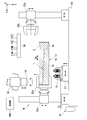
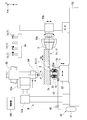
- FIG. 3 is a view taken in the direction of arrow III in FIG. 2. It is explanatory drawing which shows the structure of the controller in one Embodiment which concerns on this invention. It is a flowchart which shows the process sequence of the wing
- the blade material 1 a is processed to form the blade 1.
- the wing 1 includes a wing portion 2 that is long in the longitudinal direction Dw, which is one direction, and a mounting portion 3 that is provided at an end of the wing portion 2 in the longitudinal direction Dw.
- the surface of the wing part 2 forms a three-dimensional curved surface.
- the attachment part 3 is a part attached to the rotor shaft of a rotary machine, for example.
- the wing material 1 a has a rectangular parallelepiped shape whose outer shape is larger than that of the wing 1.
- the wing material 1 a includes a wing forming portion 2 a that becomes the wing portion 2 and an attachment forming portion 3 a that becomes the attachment portion 3.
- the blade material 1a, the intermediate material in the process of forming the blade 1 from the blade material 1a, and the blade 1 are collectively referred to as a blade-formed product 1d.
- the longitudinal direction Dw of the blade 1 is also the longitudinal direction of the blade material 1a and the intermediate material.
- the processing device M that processes the wing material 1a into the wing 1 is an NC (Numerical Control) processing device.
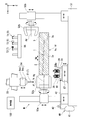
- the processing apparatus M includes a base 51, a first work gripping machine 52a, a first gripping movement mechanism 53a, a second work gripping machine 52b, a second gripping movement mechanism 53b, a tool
- the drive mechanism 54, the tool moving mechanism 55, the tool station 56, the support tool 10, the support tool moving mechanism 57, the fluid supply device 40, and the controller 100 are provided.
- the first workpiece gripping machine 52a grips one end portion in the longitudinal direction Dw of the blade forming product 1d.
- the first gripping moving mechanism 53 a moves the first work gripping machine 52 a relative to the base 51.
- the second workpiece gripping machine 52b grips the other end in the longitudinal direction Dw of the blade forming product 1d.
- the second gripping movement mechanism 53 b moves the second workpiece gripping machine 52 b relative to the base 51.
- the tool driving mechanism 54 drives the processing tool T that processes the blade material 1a and the intermediate material.
- the tool moving mechanism 55 moves the tool driving mechanism 54 relative to the base 51 at least at a portion where the processing tool T is mounted. In the tool station 56, a plurality of processing tools T are placed.
- the support 10 supports the wing forming product 1d.
- the support tool moving mechanism 57 moves the support tool 10 relative to the base 51.
- the fluid supplier 40 supplies a driving fluid to the support 10.
- the controller 100 controls the operation of the above devices and the like.
- the vertical direction is the Z direction
- the direction perpendicular to the Z direction is the Y direction
- the direction perpendicular to the Z direction and the Y direction is the X direction.
- the first gripping moving mechanism 53a moves the first workpiece gripper 52a relative to the base 51 at least in the X direction, the Y direction, the Z direction, and the circumferential direction with reference to the gripping axis Ag of the first workpiece gripper 52a. Move relative.
- the second gripping movement mechanism 53b also moves the second workpiece gripping machine 52b from the base 51 in the X direction, the Y direction, the Z direction, and the gripping axis Ag of the second workpiece gripping machine 52b. At least relative movement in the circumferential direction with reference to.
- the tool driving mechanism 54 includes a spindle 54s on which the processing tool T is mounted, and a spindle rotating mechanism 54d that rotates the spindle 54s.
- the tool moving mechanism 55 moves at least the spindle 54s in the tool driving mechanism 54 relative to the base 51 in the X direction, the Y direction, and the Z direction. Further, the tool moving mechanism 55 rotates at least the spindle 54s in the tool driving mechanism 54 around an axis extending in the X direction, an axis extending in the Y direction, and an axis extending in the Z direction.
- the support tool moving mechanism 57 moves the support tool 10 relative to the base 51 at least in the X direction, the Y direction, and the Z direction.
- the fluid supplier 40 is provided in the fluid line 42, a fluid discharge source 41 that discharges a fluid having a pressure equal to or higher than a certain pressure, a fluid line 42 that guides the fluid from the fluid discharge source 41 to the support 10, and the fluid line 42.
- the fluid discharged from the fluid discharge source 41 may be a gas such as air or a liquid such as oil.
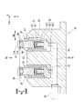
- the support 10 includes a plurality of support cylinders 20 and a cylinder base 11 to which the plurality of support cylinders 20 are attached.
- the plurality of support cylinders 20 are attached to the cylinder base 11.
- the support cylinder 20 includes a pin 21, a casing 25, a follow-up mechanism 31, and a pin restraining mechanism 35.
- the casing 25 covers the base end portion of the pin 21 so as to be displaceable in the pin extending direction Dp in which the pin 21 extends.
- the follow-up mechanism 31 causes the position of the pin 21 in the pin extending direction Dp to follow the movement of the surface position of the blade forming product 1d in the pin extending direction Dp.
- the pin restraining mechanism 35 restrains the relative position of the pin 21 with respect to the casing 25 in the pin extending direction Dp.
- one side of the pin extending direction Dp is a distal end side, and the opposite side is a proximal end side.
- the casing 25 is provided with a pin base end portion that is a portion on the base end side of the pin 21, a follow-up mechanism 31, and a pin restraining mechanism 35, and a cylinder chamber 26 into which fluid from the fluid supplier 40 flows. Is formed. Further, the casing 25 has a pin hole 27 through which the pin 21 is inserted from the cylinder chamber 26 in the pin extending direction Dp, and an inlet 28 that receives the fluid from the fluid supplier 40 in the cylinder chamber 26. And are formed.
- the pin 21 has a pin body 22 that is cylindrical with an axis extending in the pin extending direction Dp as a center, and a contact seat 24 that contacts the wing forming product 1d.
- the pin main body 22 is formed with a cylindrical hole 23 that is recessed from the proximal end side toward the distal end side.
- the contact seat 24 is fixed to the tip side of the pin body 22 in the pin extending direction Dp.
- the contact seat 24 closes the opening on the distal end side in the pin extending direction Dp. Therefore, this contact seat 24 forms the tip of the pin 21.
- the follow-up mechanism 31 includes a guide rod 32 and a spring 33 as an elastic member.
- the guide rod 32 guides the movement of the pin 21 in the pin extending direction Dp.
- the spring 33 biases the pin 21 in the pin extending direction Dp and to the side protruding from the casing 25.
- the guide rod 32 has a cylindrical shape and extends in the pin extending direction Dp in the cylinder chamber 26 from the bottom forming the base end side of the casing 25.
- the distal end side portion of the guide rod 32 is inserted into the hole 23 of the pin body 22.
- the spring 33 is disposed in the hole 23 of the pin body 22 and between the guide rod 32 and the bottom surface of the hole 23.
- the spring 33 is in contact with the pin body 22 and the guide rod 32 even when the pin 21 is located at the maximum projecting position.
- the spring 33 contracts when a load is applied to the pin 21 located at the maximum projecting position toward the proximal end side in the pin extending direction Dp, and a biasing force is generated on the distal end side in the pin extending direction Dp.
- the outer periphery of the base end portion of the pin 21 is covered with a cylindrical collet 36.
- the collet 36 is formed to be elastically deformable from the outer peripheral side toward the inner peripheral side.
- a fluid chamber 29 into which the fluid from the fluid supplier 40 flows is formed between the outer peripheral side of the collet 36 and the inner peripheral surface of the casing 25.
- the fluid chamber 29 is a part of the cylinder chamber 26.
- the pin restraining mechanism 35 includes a collet 36, a fluid chamber 29 in the casing 25, and an inflow port 28 formed in the casing 25.
- the collet 36 When a fluid with a constant pressure is supplied from the inlet 28 of the casing 25 to the fluid chamber 29, the collet 36 is elastically deformed toward the inner peripheral side by the pressure of the fluid and grips the proximal end portion of the pin 21. . By holding the pin 21 by the collet 36, the pin 21 is restrained so as not to move in the pin extending direction Dp. That is, the collet 36 constitutes a pin gripping member.
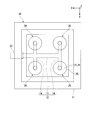
- the casings 25 of the plurality of support cylinders 20 are embedded and fixed.
- the pin extending directions Dp of the pins 21 of the plurality of support cylinders 20 are aligned with each other when the casing 25 is fixed to the cylinder base 11. That is, the pin extending direction Dp in each pin 21 is the same direction. In addition, the pin extending direction Dp in each pin 21 may not be the same direction. Further, the positions of the pins 21 of the plurality of support cylinders 20 in the pin extending direction Dp are the same as each other in a state where the pins 21 are located at the maximum projecting positions.
- the cylinder base 11 is formed with a flow path 12 that receives the fluid from the fluid line 42 of the fluid supplier 40 and guides the fluid to the inlet 28 of each casing 25 in the plurality of support cylinders 20.
- the flow path 12 includes a main flow path 13 and a plurality of branch flow paths 14.
- the main flow path 13 is connected to a fluid line 42 of the fluid supplier 40.
- the main flow path 13 receives the fluid from the fluid line 42.
- the branch channel 14 branches from the main channel 13 for each of the plurality of support cylinders 20 and is connected to the inlet 28 of each casing 25. For this reason, it is not necessary to provide the fluid line 42 connected to the cylinder base 11 for each of the plurality of support cylinders 20, and the fluid line 42 can be integrated.
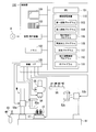
- the controller 100 is a computer. As shown in FIG. 4, the controller 100 includes a CPU (Central Processing Unit) 101 that performs various operations, a memory 102 that serves as a work area of the CPU 101, an auxiliary storage device 110 such as a hard disk drive, a keyboard, and the like.
- the device interface 105 for transmitting and receiving various signals between the manual input device 103, the display device 104, and each mechanism described above of the processing device M, and the disk-type storage medium D And a storage / reproduction device 106 that performs data storage processing and reproduction processing.
- the auxiliary storage device 110 stores an OS (Operating System) program 111, a machining order control program 112, and programs 113 to 117 executed in individual processes in blade processing.
- OS Operating System
- the first gripping program 113 is a program for executing gripping and releasing of the blade forming product 1d by the first workpiece gripping machine 52a.
- the second gripping program 114 is a program that causes the second workpiece gripping machine 52b to grip and release the blade forming product 1d.
- the attachment part machining program 115 is a program executed when machining the attachment formation part 3a in the blade material 1a.
- the blade processing program 116 is a program executed when processing the blade forming portion 2a in the blade material 1a.
- the support program 117 is a program for executing support of the wing forming product 1 d by the support tool 10.
- these programs 113 to 117 at least the attachment part machining program 115 and the wing part machining program 116 are based on various data input from the manual input device 103 by the operator of the machining apparatus M before the wing machining.
- Program set in the auxiliary storage device 110 Each of the attachment part machining program 115 and the blade part machining program 116 is a collection of data obtained by quantifying the position of the machining tool T or the like.
- the attachment portion machining program 115 and the wing portion machining program 116 may be ones in which various data are taken from the disk-type storage medium D by the storage / reproduction device 106.
- the machining order control program 112 is a program for instructing execution of the programs 113 to 117 executed in individual steps in blade processing.
- the processing sequence control program 112 and the OS program 111 are taken into the auxiliary storage device 110 from the disk type storage medium D via the storage / reproduction device 106, for example. Note that all of the programs 111 to 117 may be taken into the auxiliary storage device 110 from an external computer via a communication network.
- the control execution unit of the controller includes the memory 102 in which the programs 111 to 117 are expanded, and the CPU 101 that executes the programs 111 to 117 expanded on the memory 102.
- each step in the region surrounded by the alternate long and short dash line is a step performed by executing the processing sequence control program 112.
- the first workpiece gripper 52a grips the blade material 1a (S10: first gripping step).
- the CPU 101 of the controller 100 receives an input from the manual input device 103 under the execution of the first gripping program 113, and transmits a control signal to the first workpiece gripper 52a and the first gripping moving mechanism 53a. To make them work.
- the first workpiece gripping machine 52a grips the end portion in the longitudinal direction Dw of the blade material 1a.
- the end of the blade material 1a gripped by the first workpiece gripping machine 52a is a part of the blade forming portion 2a of the blade material 1a.
- the CPU 101 activates the attachment portion machining program 115 and executes the attachment portion machining program 115. Under the execution of the attachment portion machining program 115, the CPU 101 transmits control signals to the tool driving mechanism 54 and the tool movement mechanism 55 to operate them, and attaches the attachment forming portion 3a in the blade material 1a to them.
- the controller 100 drives the tool driving mechanism 54 and the tool moving mechanism 55 as shown in FIG.
- the tool driving mechanism 54 and the tool moving mechanism 55 are processing tools for processing the attachment forming portion 3a instructed from the controller 100 among the plurality of processing tools T (T1 to T4) placed in the tool station 56. T1 is mounted on the spindle 54s.
- the processing tool T1 mounted on the tool driving mechanism 54 processes the attachment forming portion 3a in the blade material 1a to form the attaching portion 3.
- the first gripping movement mechanism 53a is driven as necessary to move and / or rotate the blade material 1a gripped by the first work gripping machine 52a.
- the attachment forming portion 3a in the blade material 1a is processed into the attachment portion 3 by the execution of the attachment portion processing step (S21), and the blade material 1a becomes the first intermediate material 1b (see FIG. 8).
- the CPU 101 instructs the CPU 101 itself to execute the second gripping program 114 under the execution of the machining order control program 112 (S12: second gripping instruction step).
- the CPU 101 activates the second gripping program 114 and executes the second gripping program 114. Under the execution of the second gripping program 114, the CPU 101 transmits control signals to the second workpiece gripper 52b and the second gripping movement mechanism 53b to operate them, and as shown in FIG. The attachment part 3 in the intermediate material 1b is gripped by the second workpiece gripping machine 52b (S22: second gripping step).
- the CPU 101 executes the first gripping program 113 that causes the CPU 101 itself to release the gripping of the blade forming portion 2a by the first workpiece gripping machine 52a under the execution of the machining order control program 112. Execution is instructed (S13: first grip release instruction step).
- the CPU 101 activates the first gripping program 113 and executes the first gripping program 113. Under the execution of the first gripping program 113, the CPU 101 transmits control signals to the first workpiece gripper 52a and the first gripping movement mechanism 53a to operate them, and the first workpiece gripper 52a The holding of the blade forming part 2a is released (S23: first holding releasing process).
- the CPU 101 instructs the CPU 101 itself to execute the support program 117 under the execution of the processing order control program 112 (S24: support instruction step), and the blade processing program 116. Is instructed to execute (S25: second processing instruction step).
- the CPU 101 activates the support program 117 and executes the support program 117. Under the execution of the support program 117, the CPU 101 transmits a control signal to the second gripping movement mechanism 53b, the support tool movement mechanism 57, and the fluid regulating valve 43 of the fluid supply device 40 to operate it. As shown in FIG. 9, the wing forming part 2a in the first intermediate material 1b held by the second workpiece holding machine 52b is supported by the support 10 (S24: support step). Further, the CPU 101 activates the blade processing program 116 and executes the blade processing program 116.
- the CPU 101 transmits control signals to the second gripping movement mechanism 53b, the tool driving mechanism 54, and the tool movement mechanism 55 to operate them, and to the first intermediate movement
- the blade forming part 2a in the material 1b is processed (S25: blade part processing step).
- the controller 100 operates the second gripping movement mechanism 53b and the support tool moving mechanism 57 to position the blade forming portion 2a in the first intermediate material 1b directly above the support tool 10, and this Each pin 21 of the support 10 is brought into contact with the wing forming portion 2a.
- the longitudinal direction Dw of the first intermediate material 1b is the Y direction. That is, the longitudinal direction Dw of the first intermediate material 1 b is a horizontal direction perpendicular to the Z direction, and is a direction perpendicular to the pin extending direction Dp of each pin 21 in the support 10.
- each of the plurality of pins 21 of the support tool 10 contacts the downward surface of the blade forming portion 2a in the first intermediate material 1b.
- the seats 24 are in contact with each other.
- the follower mechanism 31 of the support cylinder 20 moves the position of the surface of the first intermediate material 1b in the pin extending direction Dp to the pin extending direction. The position of the pin 21 at Dp follows.
- the controller 100 causes the fluid regulating valve 43 of the fluid supply device 40 to open in this supporting step (S24). As a result, the fluid adjustment valve 43 is opened, and the fluid from the fluid discharge source 41 is supplied to the support 10 through the fluid line 42.
- This fluid flows into the fluid chambers 29 of the plurality of support cylinders 20 through the main flow path 13 and the branch flow path 14 of the cylinder base 11, and elastically deforms the collet 36 toward the inner peripheral side.
- the collet 36 holds the proximal end portion of the pin 21 and restrains the pin 21 so as not to move in the pin extending direction Dp. Due to the restraint of the pin 21, the blade forming portion 2a in the first intermediate material 1b is supported by the support 10 from below.
- the controller 100 drives the tool driving mechanism 54 and the tool moving mechanism 55.
- the tool driving mechanism 54 and the tool moving mechanism 55 first place the processing tool T1 mounted on the spindle 54s of the tool driving mechanism 54 at the original position in the tool station 56.
- the machining tool T3 for machining the blade forming portion 2a designated by the controller 100 is mounted on the spindle 54s.
- the processing tool T3 attached to the tool driving mechanism 54 processes the upper portion of the blade forming portion 2a in the first intermediate material 1b.
- the attachment portion 3 of the first intermediate material 1b is gripped by the second workpiece gripping machine 52b, and the blade forming portion 2a is supported by the support tool 10.
- the support 10 need not be moved at all, but may be moved.
- the support tool 10 may be moved so that both face each other.
- the movement of the machining tool T3 is stopped, the machining is temporarily stopped, and the pin 21 restraint of the support tool 10 is released, and then the support tool 10 is moved so as to face the machining tool T3. Then, after restraining the pin 21 of the support tool 10, processing with the processing tool T3 is started again.
- the first intermediate material 1b becomes the second intermediate material 1c (see FIG. 10).
- the controller 100 drives the second gripping movement mechanism 53b to grip the second workpiece.
- the second intermediate material 1c gripped by the second workpiece gripping machine 52b is moved upward to separate the support 10 and the second intermediate material 1c.
- the controller 100 causes the fluid regulating valve 43 of the fluid supply device 40 to perform a closing operation to restrain the pin 21 of the support tool 10. Is released.
- the second gripping movement mechanism 53b is further driven, and as shown in FIG. 10, the second intermediate material c gripped by the second workpiece gripping machine 52b and the second workpiece gripping machine 52b are The workpiece gripper 52b is reversed around the grip axis Ag. As a result, in the second intermediate material 1c, the lower part becomes the upper part, and the upper part becomes the lower part.
- the controller 100 sets the second gripping movement mechanism 53b and the support tool moving mechanism 57 so that the plurality of pins 21 of the support tool 10 are in contact with the downward surface of the blade forming portion 2a in the second intermediate material 1c. At least one of them is driven. As a result, the plurality of pins 21 of the support 10 sequentially contact the downward surface of the blade forming portion 2a in the second intermediate material 1c. Even in this process, when the contact seat 24 of the pin 21 comes into contact with the surface of the second intermediate material 1c, the follower mechanism 31 of the support cylinder 20 moves the position of the surface of the second intermediate material 1c in the pin extending direction Dp. The position of the pin 21 in the pin extending direction Dp follows.
- blade formation part 2a in the 2nd intermediate material 1c is a surface already processed, it has comprised the three-dimensional curved surface.
- the controller 100 causes the fluid regulating valve 43 of the fluid supplier 40 to open.
- the fluid adjustment valve 43 is opened, and the fluid from the fluid discharge source 41 is supplied to the support 10 through the fluid line 42.
- the collet 36 of the support 10 grips the proximal end portion of the pin 21 and restrains the pin 21 so as not to move in the pin extending direction Dp. Due to the restraint of the pin 21, the blade forming portion 2a in the second intermediate material 1c is supported by the support 10 from below.
- the controller 100 drives the tool driving mechanism 54 and the tool moving mechanism 55.
- the processing tool T3 attached to the tool driving mechanism 54 processes the upper portion of the blade forming portion 2a in the second intermediate material 1c.
- the attachment portion 3 of the second intermediate material 1c is gripped by the second workpiece gripping machine 52b, and the blade forming portion 2a is supported by the support tool 10.
- the support 10 need not be moved at all, but may be moved as described above.
- the processing tool is replaced with a grinding tool.
- the blade surface formed by roughing is ground in the same manner as described above with a grinding tool. That is, of the pressure surface and the suction surface of the wing formed by rough machining, one surface facing the lower side is supported by the support tool 10, and the other surface facing the upper side is ground by the grinding tool.
- the second gripping / moving mechanism 53b is reversed so that the aforementioned one surface is directed upward and the aforementioned other surface is directed downward.
- the other surface facing downward is supported by the support 10, and the one surface facing upward is ground with a grinding tool.
- each blade surface is polished.
- the grinding tool is used to adjust the surface shape of the grinding tool by using a dressing tool, and then another blade material 1a. It is preferable to prepare for processing.
- the controller 100 stores the amount of change in the tool diameter of the grinding tool due to dressing as a correction value, and when processing another blade material 1a with this grinding tool, the grinding tool with respect to the blade material 1a is stored. It is preferable to correct the relative position by this correction.
- the attachment portion 3 is formed on the other end portion side in a state where one end portion of the blade material 1a is gripped by the first work gripper 52a. Thereafter, the wing portion 2 is formed on one end portion side in a state where the attachment portion 3 on the other end side is gripped by the second workpiece gripping machine 52b. For this reason, in this embodiment, it is not necessary to separately form a fixing portion that does not constitute the blade 1 in the process of processing the blade 1 from the blade material 1a. Moreover, in the present embodiment, as described above, the blade material 1a is transferred from the first workpiece gripping machine 52a to the second workpiece gripping machine 52b, so that the blade 1 can be processed consistently with a single processing device M. it can.
- the blade material 1a is not necessary to transfer to a plurality of processing devices in the process of forming the blade 1 from the blade material 1a. For example, after forming the attachment portion 3 from the blade material with one processing device, the blade material is removed from the processing device, and the blade material is attached to another processing device, and then the blade with the other processing device. There is no need to form the wing 2 from a material.
- the manufacturing lead time of the blade 1 can be shortened.
- the quality control load of the processed blade 1 can be reduced.
- the blade forming portion 2a of the intermediate materials 1b and 1c is viewed from below while the attachment portion 3 of the intermediate materials 1b and 1c is gripped by the second workpiece gripping machine 52b.
- the wing forming portion 2a is processed by being supported by the support tool 10.
- chatter vibration Chatter Vibration
- the longitudinal direction Dw of the blade forming product 1d is a direction perpendicular to the pin extending direction Dp.
- the longitudinal direction Dw of the blade forming product 1d may not be a vertical direction as long as it has a direction component perpendicular to the pin extending direction Dp. .
- the attachment forming portion 3a in the blade material 1a when the attachment forming portion 3a in the blade material 1a is processed with the processing tool T, the attachment forming portion 3a may be supported by the support 10 from below.
- the attachment part 3 is processed by the drive of a 1st tool drive mechanism and a 1st tool movement mechanism. And you may process the wing
- the manufacturing lead time of the wing can be shortened.
- wing 1: wing, 1a: wing material, 1b: first intermediate material, 1c: second intermediate material, 1d: wing forming product, 2: wing part, 2a: wing forming part, 3: mounting part, 3a: mounting forming part 10: support, 11: cylinder base, 12: flow path, 13: main flow path, 14: branch flow path, 20: support cylinder, 21: pin, 25: casing, 26: cylinder chamber, 28: inflow port, 29: Fluid chamber, 31: Follow-up mechanism, 32: Guide rod, 33: Spring, 35: Pin restraint mechanism, 36: Collet, 40: Fluid feeder, 51: Base, 52a: First workpiece gripper, 52b: No.
- Two-work gripping machine 53a: first gripping moving mechanism, 53b: second gripping moving mechanism, 54: tool driving mechanism, 55: tool moving mechanism, 56: tool station, 57: support tool moving mechanism, 100: controller, 101: CPU, 102: memory, 1 5: device interface, 110: auxiliary storage device, 112: machining sequence control program, 113: first gripping program, 114: second gripping program, 115: mounting portion machining program, 116: wings machining program, 117: support program
Landscapes
- Engineering & Computer Science (AREA)
- Mechanical Engineering (AREA)
- General Engineering & Computer Science (AREA)
- Chemical & Material Sciences (AREA)
- Combustion & Propulsion (AREA)
- Electrical Discharge Machining, Electrochemical Machining, And Combined Machining (AREA)
- Structures Of Non-Positive Displacement Pumps (AREA)
- Jigs For Machine Tools (AREA)
- Numerical Control (AREA)
Abstract
L'invention concerne le traitement d'une lame, qui consiste à réaliser une première étape de saisie, une étape de traitement d'unité de montage, une seconde étape de saisie, une étape de libération de saisie, et une étape de traitement d'unité de lame. Dans la première étape de saisie, une partie de formation de lame (2a) pour former une unité de lame (2) dans un matériau de pale est saisie par un premier dispositif de saisie de pièce (52a). Dans l'étape de traitement d'unité de montage, une partie de formation de montage (3a) pour former une unité de montage (3) dans le matériau de lame est traitée, formant l'unité de montage (3). Dans la seconde étape de saisie, l'unité de montage (3) est saisie par un second dispositif de saisie de pièce (52b). Dans l'étape de libération de saisie, la saisie de la partie de formation de lame (2a) par le premier dispositif de saisie de pièce (52a) est libérée. Dans l'étape de traitement de partie de lame, la partie de formation de lame (2a) dans le matériau (1b) est traitée pour former une unité de lame (2).
Priority Applications (2)
| Application Number | Priority Date | Filing Date | Title |
|---|---|---|---|
| CN201680018988.1A CN107405698B (zh) | 2015-04-08 | 2016-04-06 | 叶片的加工方法及加工装置以及计算机可读取的存储介质 |
| KR1020177027299A KR102004075B1 (ko) | 2015-04-08 | 2016-04-06 | 날개의 가공 방법, 날개의 가공 장치, 이러한 가공 장치의 가공 순서 제어 프로그램 |
Applications Claiming Priority (2)
| Application Number | Priority Date | Filing Date | Title |
|---|---|---|---|
| JP2015079366A JP6214593B2 (ja) | 2015-04-08 | 2015-04-08 | 翼の加工方法、翼の加工装置、この加工装置の加工順序制御プログラム |
| JP2015-079366 | 2015-04-08 |
Publications (1)
| Publication Number | Publication Date |
|---|---|
| WO2016163408A1 true WO2016163408A1 (fr) | 2016-10-13 |
Family
ID=57073104
Family Applications (1)
| Application Number | Title | Priority Date | Filing Date |
|---|---|---|---|
| PCT/JP2016/061285 Ceased WO2016163408A1 (fr) | 2015-04-08 | 2016-04-06 | Procédé de traitement de lame, dispositif de traitement de lame, et programme de commande d'instruction de traitement pour ledit dispositif de traitement |
Country Status (4)
| Country | Link |
|---|---|
| JP (1) | JP6214593B2 (fr) |
| KR (1) | KR102004075B1 (fr) |
| CN (1) | CN107405698B (fr) |
| WO (1) | WO2016163408A1 (fr) |
Cited By (6)
| Publication number | Priority date | Publication date | Assignee | Title |
|---|---|---|---|---|
| CN110587008A (zh) * | 2019-07-31 | 2019-12-20 | 范金忠 | 一种汽轮机动叶片四轴联动铣床 |
| WO2023247056A1 (fr) * | 2022-06-24 | 2023-12-28 | Hemo Ag | Procédé et appareil de positionnement d'une pièce à usiner entre deux étaux |
| US11873118B2 (en) | 2020-06-04 | 2024-01-16 | Pacific Propeller International, LLC | System and method for improved cycle time milling and inspection |
| IT202200023562A1 (it) * | 2022-11-16 | 2024-05-16 | Mec Carp S R L | Sistema di supporto e movimentazione di semilavorati da lavorare |
| EP4431227A1 (fr) * | 2023-03-14 | 2024-09-18 | RTX Corporation | Broches affûtant un accessoire de décalage pour tourner cnc |
| CN119816396A (zh) * | 2022-09-05 | 2025-04-11 | 株式会社骏河生产Pf | 治具装置和治具单元 |
Families Citing this family (10)
| Publication number | Priority date | Publication date | Assignee | Title |
|---|---|---|---|---|
| HUE047520T2 (hu) * | 2016-11-29 | 2020-04-28 | Gf Machining Solutions Ag | Eljárás turbinalapátok forgácsoló megmunkálására |
| KR101858891B1 (ko) * | 2017-01-17 | 2018-06-28 | 두산중공업 주식회사 | 도브테일 가공 지그 |
| KR101862980B1 (ko) * | 2017-01-25 | 2018-05-31 | 두산중공업 주식회사 | 도브테일 가공 지그 |
| JP6351802B1 (ja) | 2017-06-28 | 2018-07-04 | 三菱日立パワーシステムズ株式会社 | 長尺材に自由曲面を加工する方法 |
| CN109894827A (zh) * | 2019-04-12 | 2019-06-18 | 常州凯度机电有限公司 | 一种汽轮机叶片四轴联动铣床加工方法 |
| CN110936191B (zh) * | 2019-12-10 | 2021-01-26 | 南京航空航天大学 | 一种车铣加工机床用叶片加工振动控制装置及方法 |
| KR102127519B1 (ko) * | 2020-01-17 | 2020-06-26 | 주식회사 혜성하이테크 | 블레이드 가공시스템 |
| CN112247613A (zh) * | 2020-09-14 | 2021-01-22 | 江苏大学 | 一种用于加工汽轮机静叶片端面圆弧的装夹工装及其使用方法 |
| JP7373681B1 (ja) | 2022-09-05 | 2023-11-02 | 株式会社駿河生産プラットフォーム | 治具装置、及び治具ユニット |
| JP7360574B1 (ja) | 2022-09-05 | 2023-10-13 | 株式会社駿河生産プラットフォーム | 治具装置、及び治具ユニット |
Citations (9)
| Publication number | Priority date | Publication date | Assignee | Title |
|---|---|---|---|---|
| JPS58146634U (ja) * | 1982-03-29 | 1983-10-03 | 株式会社東芝 | 工作物の支持装置 |
| JPH03234434A (ja) * | 1990-02-09 | 1991-10-18 | Suzuki Motor Corp | ワーク位置決め装置 |
| JPH06297222A (ja) * | 1993-04-09 | 1994-10-25 | Hitachi Ltd | 工作物支持装置およびそれを用いた工作機械 |
| JPH07214440A (ja) * | 1994-02-02 | 1995-08-15 | Ohashi Kogyo Kk | ブレード等弾性特性加工品のチャッキング装置 |
| EP0999002A1 (fr) * | 1998-11-06 | 2000-05-10 | Gildemeister Drehmaschinen GmbH | Tour avec broche additionelle |
| JP2005279793A (ja) * | 2004-03-29 | 2005-10-13 | Institute Of Physical & Chemical Research | 予圧サポートとこれを用いた薄肉部材の超精密加工方法 |
| JP2008023611A (ja) * | 2006-07-18 | 2008-02-07 | Miyano:Kk | 複合nc旋盤 |
| JP3172627U (ja) * | 2011-10-07 | 2012-01-05 | 伊藤 幸男 | タービンブレードの両端把持装置 |
| US20130269189A1 (en) * | 2010-09-24 | 2013-10-17 | Starragheckert Ag | Method and Device for Machining Elongate Workpieces that are not Rotationally Symmetrical in the Form of Tubine Blades |
Family Cites Families (3)
| Publication number | Priority date | Publication date | Assignee | Title |
|---|---|---|---|---|
| CN201009089Y (zh) * | 2006-12-08 | 2008-01-23 | 北京机电院高技术股份有限公司 | 一种五轴联动叶片加工中心机构 |
| GB0711697D0 (en) | 2007-06-16 | 2007-07-25 | Rolls Royce Plc | Method of manufacture |
| CN202224993U (zh) * | 2011-08-04 | 2012-05-23 | 德阳钰鑫机械制造有限公司 | 一种加工大型汽轮机组动叶片型面时的专用工装 |
-
2015
- 2015-04-08 JP JP2015079366A patent/JP6214593B2/ja active Active
-
2016
- 2016-04-06 KR KR1020177027299A patent/KR102004075B1/ko active Active
- 2016-04-06 CN CN201680018988.1A patent/CN107405698B/zh active Active
- 2016-04-06 WO PCT/JP2016/061285 patent/WO2016163408A1/fr not_active Ceased
Patent Citations (9)
| Publication number | Priority date | Publication date | Assignee | Title |
|---|---|---|---|---|
| JPS58146634U (ja) * | 1982-03-29 | 1983-10-03 | 株式会社東芝 | 工作物の支持装置 |
| JPH03234434A (ja) * | 1990-02-09 | 1991-10-18 | Suzuki Motor Corp | ワーク位置決め装置 |
| JPH06297222A (ja) * | 1993-04-09 | 1994-10-25 | Hitachi Ltd | 工作物支持装置およびそれを用いた工作機械 |
| JPH07214440A (ja) * | 1994-02-02 | 1995-08-15 | Ohashi Kogyo Kk | ブレード等弾性特性加工品のチャッキング装置 |
| EP0999002A1 (fr) * | 1998-11-06 | 2000-05-10 | Gildemeister Drehmaschinen GmbH | Tour avec broche additionelle |
| JP2005279793A (ja) * | 2004-03-29 | 2005-10-13 | Institute Of Physical & Chemical Research | 予圧サポートとこれを用いた薄肉部材の超精密加工方法 |
| JP2008023611A (ja) * | 2006-07-18 | 2008-02-07 | Miyano:Kk | 複合nc旋盤 |
| US20130269189A1 (en) * | 2010-09-24 | 2013-10-17 | Starragheckert Ag | Method and Device for Machining Elongate Workpieces that are not Rotationally Symmetrical in the Form of Tubine Blades |
| JP3172627U (ja) * | 2011-10-07 | 2012-01-05 | 伊藤 幸男 | タービンブレードの両端把持装置 |
Cited By (9)
| Publication number | Priority date | Publication date | Assignee | Title |
|---|---|---|---|---|
| CN110587008A (zh) * | 2019-07-31 | 2019-12-20 | 范金忠 | 一种汽轮机动叶片四轴联动铣床 |
| CN110587008B (zh) * | 2019-07-31 | 2021-01-15 | 帕马(上海)机床有限公司 | 一种汽轮机动叶片四轴联动铣床 |
| US11873118B2 (en) | 2020-06-04 | 2024-01-16 | Pacific Propeller International, LLC | System and method for improved cycle time milling and inspection |
| WO2023247056A1 (fr) * | 2022-06-24 | 2023-12-28 | Hemo Ag | Procédé et appareil de positionnement d'une pièce à usiner entre deux étaux |
| CN119816396A (zh) * | 2022-09-05 | 2025-04-11 | 株式会社骏河生产Pf | 治具装置和治具单元 |
| IT202200023562A1 (it) * | 2022-11-16 | 2024-05-16 | Mec Carp S R L | Sistema di supporto e movimentazione di semilavorati da lavorare |
| EP4371699A1 (fr) * | 2022-11-16 | 2024-05-22 | Mec. Carp. S.r.l. | Système pour le maintien et déplacement de pièces semi-finies a usiner |
| EP4431227A1 (fr) * | 2023-03-14 | 2024-09-18 | RTX Corporation | Broches affûtant un accessoire de décalage pour tourner cnc |
| US12109622B1 (en) | 2023-03-14 | 2024-10-08 | Rtx Corporation | Spindles peening offset fixture for CNC turning |
Also Published As
| Publication number | Publication date |
|---|---|
| CN107405698B (zh) | 2019-05-03 |
| JP6214593B2 (ja) | 2017-10-18 |
| KR20170119721A (ko) | 2017-10-27 |
| KR102004075B1 (ko) | 2019-07-25 |
| CN107405698A (zh) | 2017-11-28 |
| JP2016198837A (ja) | 2016-12-01 |
Similar Documents
| Publication | Publication Date | Title |
|---|---|---|
| JP6214593B2 (ja) | 翼の加工方法、翼の加工装置、この加工装置の加工順序制御プログラム | |
| JP5613864B2 (ja) | 加工装置 | |
| JP6773712B2 (ja) | ロボット加工システム | |
| JP6312327B2 (ja) | 支持方法、加工方法、及びこれらの方法を実行する装置 | |
| CN114630740B (zh) | 工件把持装置 | |
| US10195706B2 (en) | Object fastening device for fastening object to receiving part, machine tool, robot, and method of fastening object to receiving part | |
| JP6407810B2 (ja) | 加工ツール回転数とワーク送り速度とを調整する加工システム | |
| CN108115209B (zh) | 涡轮叶片的切削加工的方法 | |
| JP2006297520A (ja) | 多軸球面研削装置及び研削方法 | |
| JP6943693B2 (ja) | 加工装置及びそれを用いた加工方法 | |
| CN111867757B (zh) | 机床的主轴装置 | |
| CN104772629B (zh) | 机床 | |
| JP6943691B2 (ja) | 加工装置及びそれを用いた加工方法 | |
| JP6927779B2 (ja) | 加工装置及びそれを用いた加工方法 | |
| CN207564241U (zh) | 一种机床及其抛毛刺机构 | |
| JP2019155540A (ja) | 加工装置およびそれを用いる加工方法 | |
| JP7156897B2 (ja) | 工作機械 | |
| JP2017170601A (ja) | クーラントノズル自動交換装置 | |
| JP6405115B2 (ja) | 孔加工方法、シリンダブロックの製造方法および孔加工機 | |
| JP4020832B2 (ja) | 宝石類の外面研削装置 | |
| JP2019181630A (ja) | ワーク保持装置 | |
| JP2005007725A (ja) | 宝石類の外面研削装置用ワーク保持機構 | |
| KR20160013463A (ko) | 정밀 멀티성형드레싱 가공장치 및 가공방법 |
Legal Events
| Date | Code | Title | Description |
|---|---|---|---|
| 121 | Ep: the epo has been informed by wipo that ep was designated in this application |
Ref document number: 16776574 Country of ref document: EP Kind code of ref document: A1 |
|
| ENP | Entry into the national phase |
Ref document number: 20177027299 Country of ref document: KR Kind code of ref document: A |
|
| NENP | Non-entry into the national phase |
Ref country code: DE |
|
| 122 | Ep: pct application non-entry in european phase |
Ref document number: 16776574 Country of ref document: EP Kind code of ref document: A1 |