WO2016163471A1 - Station de base et terminal sans fil - Google Patents
Station de base et terminal sans fil Download PDFInfo
- Publication number
- WO2016163471A1 WO2016163471A1 PCT/JP2016/061430 JP2016061430W WO2016163471A1 WO 2016163471 A1 WO2016163471 A1 WO 2016163471A1 JP 2016061430 W JP2016061430 W JP 2016061430W WO 2016163471 A1 WO2016163471 A1 WO 2016163471A1
- Authority
- WO
- WIPO (PCT)
- Prior art keywords
- discovery signal
- frequency band
- control unit
- transmission
- wireless terminal
- Prior art date
- Legal status (The legal status is an assumption and is not a legal conclusion. Google has not performed a legal analysis and makes no representation as to the accuracy of the status listed.)
- Ceased
Links
Images



Classifications
-
- H—ELECTRICITY
- H04—ELECTRIC COMMUNICATION TECHNIQUE
- H04W—WIRELESS COMMUNICATION NETWORKS
- H04W8/00—Network data management
- H04W8/005—Discovery of network devices, e.g. terminals
-
- H—ELECTRICITY
- H04—ELECTRIC COMMUNICATION TECHNIQUE
- H04W—WIRELESS COMMUNICATION NETWORKS
- H04W48/00—Access restriction; Network selection; Access point selection
- H04W48/16—Discovering, processing access restriction or access information
-
- H—ELECTRICITY
- H04—ELECTRIC COMMUNICATION TECHNIQUE
- H04W—WIRELESS COMMUNICATION NETWORKS
- H04W72/00—Local resource management
- H04W72/04—Wireless resource allocation
-
- H—ELECTRICITY
- H04—ELECTRIC COMMUNICATION TECHNIQUE
- H04W—WIRELESS COMMUNICATION NETWORKS
- H04W72/00—Local resource management
- H04W72/20—Control channels or signalling for resource management
- H04W72/23—Control channels or signalling for resource management in the downlink direction of a wireless link, i.e. towards a terminal
-
- H—ELECTRICITY
- H04—ELECTRIC COMMUNICATION TECHNIQUE
- H04W—WIRELESS COMMUNICATION NETWORKS
- H04W76/00—Connection management
- H04W76/10—Connection setup
- H04W76/14—Direct-mode setup
-
- H—ELECTRICITY
- H04—ELECTRIC COMMUNICATION TECHNIQUE
- H04W—WIRELESS COMMUNICATION NETWORKS
- H04W8/00—Network data management
-
- H—ELECTRICITY
- H04—ELECTRIC COMMUNICATION TECHNIQUE
- H04W—WIRELESS COMMUNICATION NETWORKS
- H04W92/00—Interfaces specially adapted for wireless communication networks
- H04W92/16—Interfaces between hierarchically similar devices
-
- H—ELECTRICITY
- H04—ELECTRIC COMMUNICATION TECHNIQUE
- H04W—WIRELESS COMMUNICATION NETWORKS
- H04W92/00—Interfaces specially adapted for wireless communication networks
- H04W92/16—Interfaces between hierarchically similar devices
- H04W92/18—Interfaces between hierarchically similar devices between terminal devices
-
- H—ELECTRICITY
- H04—ELECTRIC COMMUNICATION TECHNIQUE
- H04W—WIRELESS COMMUNICATION NETWORKS
- H04W72/00—Local resource management
- H04W72/20—Control channels or signalling for resource management
Definitions
- the present application relates to a base station and a wireless terminal used in a mobile communication system.
- D2D ProSe Device to Device Proximity Service
- D2D ProSe modes two modes of direct discovery and direct communication are defined.
- the direct discovery is a mode in which a partner is searched by directly transmitting a discovery signal that does not designate a specific destination between wireless terminals.
- Direct communication is a mode in which data is directly transmitted between wireless terminals by specifying a specific destination (destination group).
- the base station manages a cell operated in the first frequency band.
- the base station receives a message requesting permission for the wireless terminal to transmit a discovery signal in a second frequency band different from the first frequency band from a wireless terminal connected to the cell; And a control unit that determines whether or not to permit transmission of the discovery signal in the second frequency band.
- the wireless terminal is connected to a cell operated in the first frequency band.
- the wireless terminal includes a control unit that transmits a message requesting permission to transmit a discovery signal in a second frequency band different from the first frequency band to a base station that manages the cell.
- FIG. 1 is a configuration diagram of an LTE system.
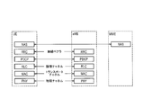
- FIG. 2 is a protocol stack diagram of a radio interface in the LTE system.
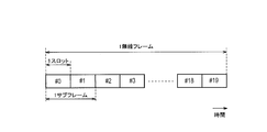
- FIG. 3 is a configuration diagram of a radio frame used in the LTE system.
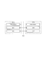
- FIG. 4 is a protocol stack diagram of “Sidelink Direct Discovery”.
- FIG. 5 is a block diagram of the UE 100.
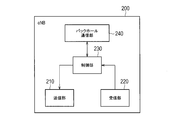
- FIG. 6 is a block diagram of the eNB 200.
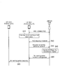
- FIG. 7 is a sequence diagram for explaining the operation according to the embodiment.
- FIG. 8 is a diagram for explaining the operation according to the embodiment.
- the base station is a base station that manages a cell operated in the first frequency band.
- the base station receives a message requesting permission for the wireless terminal to transmit a discovery signal in a second frequency band different from the first frequency band from a wireless terminal connected to the cell; And a control unit that determines whether or not to permit transmission of the discovery signal in the second frequency band.
- control unit considers a predetermined message including information indicating that the discovery signal is transmitted for public safety as the message, and permits transmission of the discovery signal in the second frequency band. It may be judged.
- the message may include information indicating a reception level of a radio signal from the cell received by the wireless terminal.
- the control unit may permit transmission of the discovery signal when the reception level is less than a threshold value.
- the control unit may transmit a response message indicating whether or not to permit transmission of the discovery signal in the second frequency band to the wireless terminal.
- the response message may include resource information that specifies a radio resource used for transmitting the discovery signal.
- the response message may include pool information that specifies a predetermined resource pool including radio resources used for transmitting the discovery signal.
- the predetermined resource pool may be a part of a resource pool set in advance in the wireless terminal.
- the wireless terminal according to the embodiment is a wireless terminal connected to a cell operated in the first frequency band.
- the wireless terminal includes a control unit that transmits a message requesting permission to transmit a discovery signal in a second frequency band different from the first frequency band to a base station that manages the cell.
- the control unit may transmit a predetermined message including information indicating that the discovery signal is transmitted for public safety as the message.
- the control unit may transmit the message only when the reception level of the radio signal from the cell is less than a threshold value.
- the control unit may include information indicating a reception level of a radio signal from the cell in the message.
- the wireless terminal may further include a receiving unit that receives from the cell a response message indicating whether the wireless terminal permits transmission of the discovery signal in the second frequency band.
- the control unit may start transmission of the discovery signal when transmission of the discovery signal is permitted.
- the response message may include resource information that specifies a radio resource used for transmitting the discovery signal.
- the control unit may transmit the discovery signal using the radio resource specified by the resource information.
- the response message may include pool information that specifies a predetermined resource pool used for transmitting the discovery signal.
- the control unit may transmit the discovery signal using a radio resource in the predetermined resource pool specified by the pool information.
- the predetermined resource pool may be a part of a resource pool set in advance in the wireless terminal.
- the control unit may periodically and / or aperiodically transmit a wireless signal for synchronization with other wireless terminals when transmission of the discovery signal is permitted.
- FIG. 1 is a diagram illustrating a configuration of an LTE system.
- the LTE system includes a UE (User Equipment) 100, an E-UTRAN (Evolved Universal Terrestrial Radio Access Network) 10, and an EPC (Evolved Packet Core) 20.
- UE User Equipment
- E-UTRAN Evolved Universal Terrestrial Radio Access Network
- EPC Evolved Packet Core
- the UE 100 corresponds to a wireless terminal.
- the UE 100 is a mobile communication device.
- the UE 100 performs radio communication with a cell (serving cell).
- the configuration of the UE 100 will be described later.
- the E-UTRAN 10 corresponds to a radio access network.
- the E-UTRAN 10 includes an eNB (evolved Node-B) 200.
- the eNB 200 corresponds to a base station.
- the eNB 200 is connected to each other via the X2 interface. The configuration of the eNB 200 will be described later.
- ENB 200 manages one or a plurality of cells.
- the eNB 200 performs radio communication with the UE 100 that has established a connection with the own cell.
- the eNB 200 has a radio resource management (RRM) function, a routing function of user data (hereinafter simply referred to as “data”), a measurement control function for mobility control / scheduling, and the like.
- RRM radio resource management
- Cell is used as a term indicating a minimum unit of a wireless communication area.
- the “cell” may also be used as a term indicating a function of performing wireless communication with the UE 100.
- the EPC 20 corresponds to a core network.
- the EPC 20 includes an MME (Mobility Management Entity) / S-GW (Serving-Gateway) 300.
- MME Mobility Management Entity
- S-GW Serving-Gateway
- MME performs various mobility control etc. with respect to UE100.
- the S-GW performs data transfer control.
- the MME / S-GW 300 is connected to the eNB 200 via the S1 interface.
- the E-UTRAN 10 and the EPC 20 constitute a network.
- FIG. 2 is a protocol stack diagram of a radio interface in the LTE system. As shown in FIG. 2, the radio interface protocol is divided into the first to third layers of the OSI reference model.
- the first layer is a physical (PHY) layer.
- the second layer includes a MAC (Medium Access Control) layer, an RLC (Radio Link Control) layer, and a PDCP (Packet Data Convergence Protocol) layer.
- the third layer includes an RRC (Radio Resource Control) layer.
- the physical layer performs encoding / decoding, modulation / demodulation, antenna mapping / demapping, and resource mapping / demapping.
- Data and control signals are transmitted between the physical layer of the UE 100 and the physical layer of the eNB 200 via a physical channel.
- the MAC layer performs data priority control, retransmission processing by hybrid ARQ (HARQ), random access procedure, and the like. Data and control signals are transmitted between the MAC layer of the UE 100 and the MAC layer of the eNB 200 via a transport channel.
- the MAC layer of the eNB 200 includes a scheduler. The scheduler determines an uplink / downlink transport format (transport block size, modulation / coding scheme (MCS)) and an allocation resource block to the UE 100.
- MCS modulation / coding scheme
- the RLC layer transmits data to the RLC layer on the receiving side using the functions of the MAC layer and the physical layer. Data and control signals are transmitted between the RLC layer of the UE 100 and the RLC layer of the eNB 200 via a logical channel.
- the PDCP layer performs header compression / decompression and encryption / decryption.
- the RRC layer is defined only in the control plane that handles control signals. Messages for various settings (RRC messages) are transmitted between the RRC layer of the UE 100 and the RRC layer of the eNB 200.
- the RRC layer controls the logical channel, the transport channel, and the physical channel according to establishment, re-establishment, and release of the radio bearer.
- RRC connection connection between the RRC layer of the UE 100 and the RRC layer of the eNB 200
- the UE 100 is in the RRC connected state (connected state).
- RRC connection When there is no connection (RRC connection) between the RRC layer of the UE 100 and the RRC layer of the eNB 200, the UE 100 is in the RRC idle state (idle state).
- the NAS (Non-Access Stratum) layer located above the RRC layer performs session management and mobility management.
- FIG. 3 is a configuration diagram of a radio frame used in the LTE system.
- OFDMA Orthogonal Frequency Division Multiple Access
- SC-FDMA Single Carrier Frequency Division Multiple Access
- the radio frame is composed of 10 subframes arranged in the time direction.
- Each subframe is composed of two slots arranged in the time direction.
- the length of each subframe is 1 ms.
- the length of each slot is 0.5 ms.
- Each subframe includes a plurality of resource blocks (RB) in the frequency direction.
- Each subframe includes a plurality of symbols in the time direction.
- Each resource block includes a plurality of subcarriers in the frequency direction.
- One symbol and one subcarrier constitute one resource element (RE).
- a frequency resource can be specified by a resource block, and a time resource can be specified by a subframe (or slot).
- the section of the first few symbols of each subframe is an area mainly used as a physical downlink control channel (PDCCH) for transmitting a downlink control signal. Details of the PDCCH will be described later.
- the remaining part of each subframe is an area that can be used mainly as a physical downlink shared channel (PDSCH) for transmitting downlink data.
- PDSCH physical downlink shared channel
- both ends in the frequency direction in each subframe are regions used mainly as physical uplink control channels (PUCCH) for transmitting uplink control signals.
- the remaining part of each subframe is an area that can be used as a physical uplink shared channel (PUSCH) mainly for transmitting uplink data.
- PUSCH physical uplink shared channel
- D2D ProSe In D2D ProSe, a plurality of UEs 100 transmit and receive various signals via direct radio links that do not go through the eNB 200. As modes of D2D ProSe, two modes of “direct discovery” and “direct communication” are defined. A direct radio link in D2D ProSe is referred to as a “sidelink”.
- “Sidelink” is a UE-UE interface for direct discovery and direct communication. “Sidelink” corresponds to the PC5 interface. The PC 5 is a reference point between UEs that can use the D2D proximity service used for direct discovery, direct communication, control for UE-NW relay by D2D proximity service, and user plane. In the following, direct discovery will be mainly described for D2D ProSe.
- Direct discovery is a mode in which a partner is searched by directly transmitting a discovery signal that does not designate a specific destination between UEs.
- Direct discovery is a procedure for discovering another UE 100 in the vicinity of the UE 100 using a direct radio signal in E-UTRA (Evolved Universal Terrestrial Radio Access) via the PC 5.
- E-UTRA Evolved Universal Terrestrial Radio Access
- Direct discovery is supported only when UE 100 is served by E-UTRAN (eNB 200 (cell)). When the UE 100 is connected to the cell (eNB 200) or located in the cell, the UE 100 can be provided with service by the E-UTRAN.
- FIG. 4 is a protocol stack diagram of “Direct Discovery (Discovery Direct Discovery)”.
- the “Sidelink Direct Discovery” protocol stack includes a physical (PHY) layer, a MAC layer, and a ProSe protocol.
- a discovery signal is transmitted between a physical layer of UE (A) and a physical layer of UE (B) via a physical channel called a physical side link discovery channel (PSDCH).
- a discovery signal is transmitted between the MAC layer of UE (A) and the MAC layer of UE (B) via a transport channel called a side link discovery channel (SL-DCH).
- PSDCH physical side link discovery channel
- Type 1 is a resource allocation procedure in which radio resources for transmission of discovery signals are not allocated uniquely to the UE.
- the UE 100 autonomously selects a radio resource from a resource pool used for transmitting a discovery signal.
- the UE 100 transmits a discovery signal using the selected radio resource.
- eNB200 provides the resource pool setting used for transmission of a discovery signal to UE100.
- the eNB 200 can provide the resource pool setting to the UE 100 by a broadcast signal or an individual signal.
- Type 2 is a resource allocation procedure in which radio resources for transmission of discovery signals are allocated uniquely to the UE.
- the eNB 200 allocates radio resources to the UE 100 via the RRC message.
- UE100 transmits a discovery signal using the radio
- Type 1 when the UE 100 is located in the cell coverage, the UE 100 transmits a discovery signal using radio resources in a resource pool provided in a frequency band in which the serving cell is operated. On the other hand, when the UE 100 is located outside the cell coverage, the UE 100 uses a preset resource pool.
- Type 2 the radio resource in the frequency band in which the serving cell is operated is allocated to the UE 100. UE100 transmits a discovery signal using the said radio
- FIG. 5 is a block diagram of the UE 100. As illustrated in FIG. 5, the UE 100 includes a reception unit 110, a transmission unit 120, and a control unit 130.
- the receiving unit 110 performs various types of reception under the control of the control unit 130.
- the receiving unit 110 includes an antenna and a receiver.
- the receiver converts a radio signal received by the antenna into a baseband signal (received signal) and outputs the baseband signal to the control unit 130.
- the receiving unit 110 can simultaneously receive radio signals at two different frequencies.
- the UE 100 includes two receivers (2 RX Chain).
- the UE 100 can receive a cellular radio signal using one receiver, and can receive a D2D ProSe radio signal using the other receiver.
- the transmission unit 120 performs various transmissions under the control of the control unit 130.
- the transmission unit 120 includes an antenna and a transmitter.
- the transmitter converts the baseband signal (transmission signal) output from the control unit 130 into a radio signal and transmits it from the antenna.
- the control unit 130 performs various controls in the UE 100.
- the control unit 130 includes a processor and a memory.
- the memory stores a program executed by the processor and information used for processing by the processor.
- the processor includes a baseband processor that performs modulation / demodulation and encoding / decoding of the baseband signal, and a CPU (Central Processing Unit) that executes various processes by executing programs stored in the memory.
- the processor may include a codec that performs encoding / decoding of an audio / video signal.
- the processor executes various processes described later and various communication protocols described above.
- FIG. 6 is a block diagram of the eNB 200. As illustrated in FIG. 6, the eNB 200 includes a transmission unit 210, a reception unit 220, a control unit 230, and a backhaul communication unit 240.
- the transmission unit 210 performs various transmissions under the control of the control unit 230.
- the transmission unit 210 includes an antenna and a transmitter.
- the transmitter converts the baseband signal (transmission signal) output from the control unit 230 into a radio signal and transmits it from the antenna.
- the receiving unit 220 performs various types of reception under the control of the control unit 230.
- the receiving unit 220 includes an antenna and a receiver.
- the receiver converts a radio signal received by the antenna into a baseband signal (received signal) and outputs the baseband signal to the control unit 230.
- the control unit 230 performs various controls in the eNB 200.
- the control unit 230 includes a processor and a memory.
- the memory stores a program executed by the processor and information used for processing by the processor.
- the processor includes a baseband processor that performs modulation / demodulation and encoding / decoding of the baseband signal, and a CPU (Central Processing Unit) that executes various processes by executing programs stored in the memory.
- the processor executes various processes described later and various communication protocols described above.
- the backhaul communication unit 240 is connected to the neighboring eNB 200 via the X2 interface.
- the backhaul communication unit 240 is connected to the MME / S-GW 300 via the S1 interface.
- the backhaul communication unit 240 is used for communication performed on the X2 interface, communication performed on the S1 interface, and the like.
- FIG. 7 is a sequence diagram for explaining the operation according to the embodiment.
- FIG. 8 is a diagram for explaining the operation according to the embodiment.
- the mobile communication system includes a UE 100-1 (Announcing UE), a UE 100-2 (Monitoring UE), and an eNB 200.
- an RRC connection is established between the UE 100-1 and a cell (eNB 200) operated in the first frequency band. That is, the UE 100-1 has established an RRC connection with the cell (serving cell). UE 100-1 is in the RRC connected state. The UE 100-1 is located in the cell coverage (In coverage). On the other hand, the UE 100-2 is located outside the cell coverage (Out of coverage). UE 100-2 is in the RRC idle state.
- the UE 100-1 desires to transmit a discovery signal to a UE outside the coverage of the serving cell while being connected to the serving cell.
- the current specification does not define a method for transmitting a discovery signal in this case. Therefore, the UE 100-1 loses the opportunity to transmit a discovery signal. As a result, there is a possibility that the D2D proximity service cannot be used effectively.
- the following is a method for effectively using the D2D proximity service.
- step S10 the UE 100-1 is interested in transmitting a discovery signal in a frequency band different from the first frequency band.
- the UE 100-1 determines that information for public safety (Public Safety) is to be transmitted by a discovery signal for the UE 100 located outside the cell coverage (Out of coverage).
- a resource pool for transmitting (receiving) a discovery signal when UE 100-1 is located outside the cell coverage is set in advance.
- the UE 100-1 uses the first frequency band. It is interesting to transmit discovery signals in a second frequency band different from the band.
- the information for public safety includes, for example, information on disasters (earthquakes, fires, etc.), information used for fire fighting personnel or police personnel, and the like.
- the resource pool set in advance may be, for example, a resource pool set from the eNB 200 when establishing a connection with the cell (eNB 200), or before establishing a connection with the cell (eNB 200). It may be a resource pool that has been set. Alternatively, the resource pool set in advance may be a resource pool stored in advance in the memory of the UE 100 instead of the resource pool set from the eNB 200.
- the eNB 200 transmits information indicating a threshold value (PaC discovery threshold) for determining whether or not the UE 100 is in a partial coverage state.
- the eNB 200 may transmit threshold information to the UE 100-1 using an individual signal.
- the eNB may transmit threshold information to the UE 100-1 by a broadcast signal.
- the UE 100-1 receives information indicating the threshold from the eNB 200.
- the threshold is a value larger than the reception level of the radio signal received from the cell when UE 100-1 is located outside the cell coverage.
- the threshold is a value smaller than the reception level of the radio signal received from the cell when UE 100-1 is located near the center of the cell.
- the UE 100-1 compares the reception level of the radio signal from the serving cell with a threshold value. For example, the UE 100-1 compares the received power (RSRP: Reference Signal Received Power) of a radio signal (reference signal) from the serving cell with a threshold value. The UE 100-1 determines that it is in the partial coverage state when the received power (reception level) is less than the threshold. Alternatively, the UE 100-1 compares the reception quality (RSRQ: Reference Signal Received Quality) of the radio signal (reference signal) from the serving cell with a threshold value. The UE 100-1 determines that it is in the partial coverage state when the reception quality (reception level) is less than the threshold. When the UE 100-1 is in the partial coverage state, the UE 100-1 is not located near the center of the serving cell but near the end of the serving cell.
- RSRP Reference Signal Received Power
- the UE 100-1 executes the process of step S30.
- the UE 100-1 does not have to execute the process of step S30. That is, the UE 100-1 may transmit a message in step S30 described later only when the reception level of the radio signal from the serving cell is less than the threshold value.
- the UE 100-1 does not need to transmit the message.
- the UE 100-1 can deliver a discovery signal in a wider area outside the cell coverage near the end of the cell than near the center of the cell. Therefore, when the UE 100-1 wants to transmit a discovery signal for the UE 100 located outside the cell coverage, the UE 100-1 determines whether to transmit the message in step S30 based on the threshold. As a result, transmission of an ineffective discovery signal can be suppressed.
- the UE 100-1 may determine to transmit the message in step S30 when receiving the discovery signal from another UE 100 in the second frequency band. As a result, the UE 100-1 can transmit a discovery signal after knowing that another UE 100 exists in the vicinity of the UE 100-1.
- the UE 100-1 may transmit the message in step S30 when the reception level (RSRP and / or RSRQ) of the discovery signal received from the other UE 100 exceeds the second threshold.
- the UE 100-1 knows that another UE 100 exists in the vicinity of the UE 100-1. As a result, transmission of an ineffective discovery signal can be suppressed.
- step S20 may be omitted.
- step S30 the UE 100-1 sends a message requesting permission to transmit a discovery signal in the second frequency band (non-serving carrier) different from the first frequency band (serving carrier) to the eNB 200 (serving cell). Send.
- the eNB 200 receives the message.
- the UE 100-1 may transmit a predetermined message including information indicating that a discovery signal is transmitted for public safety (for example, flag information indicated by 1 bit) as the message.
- the UE 100-1 may include information indicating the reception level (RSRP and / or RSRQ) of the radio signal from the serving cell in the message.
- the UE 100-1 may use “SideLink (SL) UE Information” that is a message related to the D2D proximity service as a message for requesting permission.
- the UE 100-1 may use an RRC message as a message requesting permission.
- the UE 100-1 may use an RRC message when establishing an RRC connection as a message requesting permission.
- step S40 the eNB 200 that has received the message from the UE 100-1 determines whether to permit the UE 100-1 to transmit a discovery signal in the second frequency band.
- the eNB 200 When the eNB 200 receives a predetermined message including information indicating that a discovery signal is transmitted for public safety, the eNB 200 transmits the predetermined message to a second frequency band (non-carrier) different from the first frequency band (serving carrier).
- -Serving carrier may be regarded as a message requesting permission to transmit a discovery signal.
- the eNB 200 may determine whether to permit transmission of the discovery signal based on the information. Specifically, the eNB 200 permits transmission of the discovery signal when the reception level is less than the threshold value. Thereby, eNB200 can permit transmission of a discovery signal not to UE100 located near the center of a serving cell but UE100 located near the edge part of a serving cell. That is, the eNB 200 can permit only the UE 100 that can deliver the discovery signal to a wide range outside the cell coverage.
- ENB 200 can designate a radio resource used for transmitting a discovery signal when permitting transmission of a discovery signal.
- the eNB 200 performs scheduling so that the transmission timing of the uplink cellular signal and the transmission timing of the discovery signal do not match. That is, eNB 200 assigns radio resources used for transmission of discovery signals to UE 100- so that radio resources used for uplink cellular communication allocated to UE 100-1 and radio resources used for transmission of discovery signals do not overlap in the time direction. Assign to 1. Thereby, even when the UE 100-1 has only one transceiver, it can be suppressed that the UE 100-1 can execute only one of the transmission of the cellular signal and the transmission of the discovery signal.
- the eNB 200 can specify a transmission resource pool including radio resources used for transmitting the discovery signal. Specifically, the eNB 200 transmits the transmission resource pool so that the radio resource used for uplink cellular communication allocated to the UE 100-1 and the transmission resource pool including the radio resource used for transmitting the discovery signal do not overlap in the time direction. Is assigned to the UE 100-1. As illustrated in FIG. 8, the eNB 200 may designate a part of a resource pool (Pre-configured (resource pool)) preset in the UE 100-1 as a transmission resource pool. The preset resource pool is a transmission resource pool and / or a reception resource pool. The eNB 200 allocates radio resources used for cellular communication within an area (time area) that is not specified in the transmission resource pool. In FIG. 8 (right figure), the area not designated in the transmission resource pool is a part without hatching (Cell configured).
- Cell the area not designated in the transmission resource pool is a part without hatching (Cell configured).
- the eNB 200 may inquire the UE 100-1 or the network device about the resource pool information set in advance in the UE 100-1.
- the network device is a device that manages resource pool information.
- the eNB 200 transmits a response message indicating whether or not to permit transmission of the discovery signal in the second frequency band to the UE 100-1.
- the eNB 200 can transmit a response message to the UE 100 using an RRC message.
- the eNB 200 can transmit to the UE 100 as an RRC connection reconfiguration (RRC Connection Reconfiguration) message and a response message.
- RRC connection reconfiguration RRC Connection Reconfiguration
- the eNB 200 may transmit a response message only when permitting transmission of a discovery signal. Alternatively, the eNB 200 may transmit a response message when the reception level is less than the threshold value.
- ENB200 when permitting transmission of a discovery signal, may include resource information specifying a radio resource used for transmission of a discovery signal in a response message.
- eNB200 may include the pool information which designates the transmission resource pool containing the radio
- Resource information and pool information distinguish between radio resources (transmission resource pool) used for transmission of discovery signals in the second frequency band and resource allocation of discovery signals in the first frequency band in which the serving cell is operated. It may also include an identifier for Alternatively, for resource information and pool information, for example, whether the frequency band information indicating the second frequency band (E-ARFCN: E-UTRA Absolute Radio Frequency Number) or the radio resource (transmission resource pool) is for public safety Information indicating whether or not may be included.
- E-ARFCN E-UTRA Absolute Radio Frequency Number
- the radio resource (transmission resource pool) is for public safety Information indicating whether or not may be included.
- step S60 the UE 100-1 that has received the response message starts transmission of the discovery signal when transmission of the discovery signal is permitted. On the other hand, when the UE 100-1 is refused to transmit the discovery signal, the UE 100-1 cannot transmit the discovery signal.
- the UE 100-1 transmits a discovery signal using the radio resource specified by the resource information. Further, when the response message includes pool information, the UE 100-1 transmits a discovery signal using a radio resource in the transmission resource pool specified by the pool information.
- the transmission resource pool specified by the pool information is a part of a preset resource pool, the UE 100-1 prioritizes the pool information and transmits a discovery signal. That is, even if the UE 100-1 is a radio resource in a preset resource pool, the radio resource not included in the transmission resource pool specified by the pool information is not used for transmitting the discovery signal.
- the UE 100-1 transmits a radio signal for synchronization with another UE 100 (UE 100 located outside the cell coverage) before starting transmission of a discovery signal.
- the UE 100-2 receives the radio signal for synchronization and synchronizes with the UE 100-1. Thereafter, the UE 100-2 searches for a preset resource pool and receives a discovery signal from the UE 100-1.
- the wireless signal for synchronization is, for example, a wireless signal including a synchronization signal and a “MasterInformationBlock-SL” message.
- a synchronization signal (SLSS: Sidelink Synchronization Signal) is used for synchronization for D2D proximity service (direct discovery).
- the “MasterInformationBlock-SL” message includes information transmitted by the UE 100-1 that transmits the synchronization signal.
- the UE 100 that has received the radio signal including the “MasterInformationBlock-SL” message receives information (bandwidth (sl-Bandwidth), subframe assignment SL) used for the D2D proximity service included in the “MasterInformationBlock-SL” message.
- the direct frame number (directFrameNumber) and the direct subframe number (directSubframeNumber) are applied.
- the UE 100-1 can periodically and / or aperiodically transmit a radio signal for synchronization with another UE 100 (UE 100 located outside the cell coverage) when transmission of the discovery signal is permitted. That is, the UE 100-1 repeats transmission of radio signals for synchronization while executing the direct discovery procedure.
- the UE 100-1 terminates transmission of a radio signal for synchronization. Thereby, even if another UE 100 has noticed the existence of the UE 100-1 after a predetermined time has elapsed since the UE 100-1 started transmitting the discovery signal, the radio signal for synchronization from the UE 100-1 is transmitted. Can receive. As a result, many UEs 100 can receive the discovery signal from the UE 100-1.
- the UE 100-1 transmits a message requesting permission to transmit a discovery signal in a second frequency band (non-serving carrier) different from the first frequency band (serving carrier) to the eNB 200.
- the eNB 200 determines whether to permit transmission of the discovery signal in the second frequency band.
- eNB200 can control transmission of a discovery signal.
- interference based on discovery signal transmission can be suppressed, so that the D2D proximity service can be used effectively.
- the UE 100 may transmit a message requesting permission to transmit a commercial discovery signal to the eNB 200 in a second frequency band different from the first frequency band.
- the eNB 200 determines not only the threshold for determining whether or not the UE 100 is in the partial coverage state, but also whether the UE 100 can transmit a message for requesting permission. May be transmitted.
- the eNB 200 may transmit information indicating that only a UE 100 that supports transmission of a discovery signal for public safety can transmit a message for requesting permission.
- the eNB 200 may transmit a response message to the UE 100-1 only when rejecting transmission of the discovery signal.
- the UE 100 may start transmission of a discovery signal when a response message is not received even after a predetermined time has elapsed from transmission of a message requesting permission.
- the UE 100 can transmit a discovery signal using radio resources in a preset resource pool.
- the above-described operation can be performed using a PCell (Primary Cell) as a serving cell.
- PCell Primary Cell
- the LTE system has been described as an example of a mobile communication system.
- the embodiment is not limited to the LTE system, and the embodiment of the present invention may be applied to a system other than the LTE system.
Landscapes
- Engineering & Computer Science (AREA)
- Computer Networks & Wireless Communication (AREA)
- Signal Processing (AREA)
- Databases & Information Systems (AREA)
- Computer Security & Cryptography (AREA)
- Mobile Radio Communication Systems (AREA)
Abstract
La station de base selon le présent mode de réalisation de l'invention gère une cellule fonctionnant dans une première bande de fréquences. La station de base comprend : une unité de réception qui reçoit, en provenance d'un terminal sans fil connecté à la cellule, un message demandant l'autorisation pour le terminal sans fil de transmettre des signaux de recherche dans une deuxième bande de fréquences, différente de la première bande de fréquences ; et une unité de commande qui détermine l'opportunité d'autoriser la transmission des signaux de recherche dans la deuxième bande de fréquences.
Priority Applications (3)
| Application Number | Priority Date | Filing Date | Title |
|---|---|---|---|
| JP2017511060A JP6298218B2 (ja) | 2015-04-10 | 2016-04-07 | 通信方法、無線端末、プロセッサ及び基地局 |
| EP16776637.7A EP3282730B1 (fr) | 2015-04-10 | 2016-04-07 | Station de base et terminal sans fil |
| US15/727,872 US10433150B2 (en) | 2015-04-10 | 2017-10-09 | Communication method, radio terminal, processor and base station |
Applications Claiming Priority (2)
| Application Number | Priority Date | Filing Date | Title |
|---|---|---|---|
| JP2015-080483 | 2015-04-10 | ||
| JP2015080483 | 2015-04-10 |
Related Child Applications (1)
| Application Number | Title | Priority Date | Filing Date |
|---|---|---|---|
| US15/727,872 Continuation US10433150B2 (en) | 2015-04-10 | 2017-10-09 | Communication method, radio terminal, processor and base station |
Publications (1)
| Publication Number | Publication Date |
|---|---|
| WO2016163471A1 true WO2016163471A1 (fr) | 2016-10-13 |
Family
ID=57072273
Family Applications (1)
| Application Number | Title | Priority Date | Filing Date |
|---|---|---|---|
| PCT/JP2016/061430 Ceased WO2016163471A1 (fr) | 2015-04-10 | 2016-04-07 | Station de base et terminal sans fil |
Country Status (4)
| Country | Link |
|---|---|
| US (1) | US10433150B2 (fr) |
| EP (1) | EP3282730B1 (fr) |
| JP (2) | JP6298218B2 (fr) |
| WO (1) | WO2016163471A1 (fr) |
Families Citing this family (3)
| Publication number | Priority date | Publication date | Assignee | Title |
|---|---|---|---|---|
| CN106211261B (zh) * | 2015-04-10 | 2020-10-16 | 中兴通讯股份有限公司 | 信息处理方法及通信节点 |
| US12587820B2 (en) * | 2020-12-10 | 2026-03-24 | Qualcomm Incorporated | Frequency range 2 (FR2) non-standalone sidelink discovery |
| WO2023209668A1 (fr) * | 2022-04-29 | 2023-11-02 | Telefonaktiebolaget Lm Ericsson (Publ) | Signalisation et mécanismes pour scénarios de liaison latérale à sauts multiples de transmission de message de découverte d'ue relais |
Citations (2)
| Publication number | Priority date | Publication date | Assignee | Title |
|---|---|---|---|---|
| WO2014069221A1 (fr) * | 2012-10-29 | 2014-05-08 | 京セラ株式会社 | Système de communication mobile, terminal utilisateur, station de base, processeur et procédé de commande de communications |
| WO2015045556A1 (fr) * | 2013-09-26 | 2015-04-02 | ソニー株式会社 | Dispositif de commande de communication, procédé de commande de communication, dispositif de terminal et dispositif de traitement d'informations |
Family Cites Families (6)
| Publication number | Priority date | Publication date | Assignee | Title |
|---|---|---|---|---|
| WO2013120267A1 (fr) * | 2012-02-17 | 2013-08-22 | Renesas Mobile Corporation | Commande de communication dispositif-à-dispositif |
| WO2014051126A1 (fr) * | 2012-09-27 | 2014-04-03 | 京セラ株式会社 | Système de communication mobile, terminal utilisateur, processeur et station de base |
| US9307575B2 (en) * | 2012-11-13 | 2016-04-05 | Lg Electronics Inc. | Method and apparatus of supporting UE relay functions |
| GB2508353B (en) * | 2012-11-28 | 2015-07-22 | Broadcom Corp | Apparatuses and methods for a communication system |
| EP2943041B1 (fr) * | 2013-01-02 | 2019-09-04 | Kyocera Corporation | Système de communications mobiles, terminal utilisateur, station de base et processeur |
| US20160295623A1 (en) * | 2014-08-07 | 2016-10-06 | Telefonaktiebolaget Lm Ericsson (Publ) | Receiver Sharing Between D2D and Cellular Operations in Multi-Carrier System |
-
2016
- 2016-04-07 WO PCT/JP2016/061430 patent/WO2016163471A1/fr not_active Ceased
- 2016-04-07 EP EP16776637.7A patent/EP3282730B1/fr active Active
- 2016-04-07 JP JP2017511060A patent/JP6298218B2/ja active Active
-
2017
- 2017-10-09 US US15/727,872 patent/US10433150B2/en active Active
-
2018
- 2018-02-22 JP JP2018029981A patent/JP2018129811A/ja active Pending
Patent Citations (2)
| Publication number | Priority date | Publication date | Assignee | Title |
|---|---|---|---|---|
| WO2014069221A1 (fr) * | 2012-10-29 | 2014-05-08 | 京セラ株式会社 | Système de communication mobile, terminal utilisateur, station de base, processeur et procédé de commande de communications |
| WO2015045556A1 (fr) * | 2013-09-26 | 2015-04-02 | ソニー株式会社 | Dispositif de commande de communication, procédé de commande de communication, dispositif de terminal et dispositif de traitement d'informations |
Non-Patent Citations (3)
| Title |
|---|
| "Enhanced LTE D2D Proximity Services: Release 13 D2D WI", 3GPP TSG-RAN#66 RP-141905, XP050898614, Retrieved from the Internet <URL:http://www.3gpp.org/ftp/tsg_ran/TSG_RAN/TSGR_66/Docs/RP-141905.zip> * |
| SAMSUNG: "Signaling flows for Type 2B Resource Allocation", 3GPP TSG-RAN WG2#85BIS R2- 141388, XP050817815, Retrieved from the Internet <URL:http://www.3gpp.org/ftp/tsg_ran/WG2_RL2/TSGR2_85bis/Docs/R2-141388.zip> * |
| See also references of EP3282730A4 * |
Also Published As
| Publication number | Publication date |
|---|---|
| EP3282730B1 (fr) | 2020-12-02 |
| US20180049016A1 (en) | 2018-02-15 |
| EP3282730A4 (fr) | 2018-09-12 |
| JPWO2016163471A1 (ja) | 2017-12-28 |
| JP2018129811A (ja) | 2018-08-16 |
| EP3282730A1 (fr) | 2018-02-14 |
| US10433150B2 (en) | 2019-10-01 |
| JP6298218B2 (ja) | 2018-03-20 |
Similar Documents
| Publication | Publication Date | Title |
|---|---|---|
| US10477380B2 (en) | Base station and radio terminal | |
| JP6026549B2 (ja) | 移動通信システム、基地局及びユーザ端末 | |
| US9763273B2 (en) | Mobile communication system, user terminal, base station, processor, and communication control method | |
| US20150146637A1 (en) | Communication control method, user terminal, processor, storage medium, and base station | |
| JP6829208B2 (ja) | 無線端末及び基地局 | |
| JP6670929B2 (ja) | 無線端末及び基地局 | |
| US10362634B2 (en) | Communication control method | |
| US11197220B2 (en) | Radio terminal, communication device, and base station | |
| US10425881B2 (en) | User terminal, network apparatus, and processor | |
| WO2017026409A1 (fr) | Terminal sans fil | |
| US9924496B2 (en) | Network apparatus and user terminal | |
| US20180255610A1 (en) | Radio terminal, processor, and network device | |
| JP6615729B2 (ja) | 通信方法、ユーザ端末及びプロセッサ | |
| US10433150B2 (en) | Communication method, radio terminal, processor and base station | |
| US9900763B2 (en) | User terminal for determining whether to transmit synchronization signal in response to a received power | |
| JP6140013B2 (ja) | 移動通信システム、ユーザ端末、ネットワーク装置及びプロセッサ | |
| WO2014157393A1 (fr) | Système de communication mobile, station de base et terminal utilisateur | |
| US20160183320A1 (en) | Base station and user terminal |
Legal Events
| Date | Code | Title | Description |
|---|---|---|---|
| 121 | Ep: the epo has been informed by wipo that ep was designated in this application |
Ref document number: 16776637 Country of ref document: EP Kind code of ref document: A1 |
|
| ENP | Entry into the national phase |
Ref document number: 2017511060 Country of ref document: JP Kind code of ref document: A |
|
| NENP | Non-entry into the national phase |
Ref country code: DE |