WO2016167140A1 - Dispositif de capture d'image, procédé de capture d'image et programme - Google Patents
Dispositif de capture d'image, procédé de capture d'image et programme Download PDFInfo
- Publication number
- WO2016167140A1 WO2016167140A1 PCT/JP2016/060897 JP2016060897W WO2016167140A1 WO 2016167140 A1 WO2016167140 A1 WO 2016167140A1 JP 2016060897 W JP2016060897 W JP 2016060897W WO 2016167140 A1 WO2016167140 A1 WO 2016167140A1
- Authority
- WO
- WIPO (PCT)
- Prior art keywords
- short
- long
- pixels
- exposure
- image
- Prior art date
- Legal status (The legal status is an assumption and is not a legal conclusion. Google has not performed a legal analysis and makes no representation as to the accuracy of the status listed.)
- Ceased
Links
Images


Classifications
-
- H—ELECTRICITY
- H04—ELECTRIC COMMUNICATION TECHNIQUE
- H04N—PICTORIAL COMMUNICATION, e.g. TELEVISION
- H04N25/00—Circuitry of solid-state image sensors [SSIS]; Control thereof
- H04N25/40—Extracting pixel data from image sensors by controlling scanning circuits, e.g. by modifying the number of pixels sampled or to be sampled
-
- H—ELECTRICITY
- H04—ELECTRIC COMMUNICATION TECHNIQUE
- H04N—PICTORIAL COMMUNICATION, e.g. TELEVISION
- H04N23/00—Cameras or camera modules comprising electronic image sensors; Control thereof
- H04N23/70—Circuitry for compensating brightness variation in the scene
- H04N23/75—Circuitry for compensating brightness variation in the scene by influencing optical camera components
-
- H—ELECTRICITY
- H04—ELECTRIC COMMUNICATION TECHNIQUE
- H04N—PICTORIAL COMMUNICATION, e.g. TELEVISION
- H04N25/00—Circuitry of solid-state image sensors [SSIS]; Control thereof
- H04N25/50—Control of the SSIS exposure
- H04N25/57—Control of the dynamic range
Definitions
- the present technology relates to an imaging device, an imaging method, and a program.
- the present invention relates to an imaging apparatus, an imaging method, and a program that can perform imaging with an expanded dynamic range.
- CCD Charge Coupled Device
- CMOS Complementary Metal Oxide Semiconductor
- CMOS image sensor as a method of expanding the dynamic range, a method of adjusting the exposure time by turning the electronic shutter at a high speed, a method of photographing a plurality of frames at a high speed, and a photoelectric conversion of the light receiving unit A method of making the characteristic logarithmic response is known.
- pixels having different exposure times or different sensitivities in a local area of a predetermined size are replaced with pixels having the other exposure time or sensitivity.
- It has been proposed to increase the dynamic range by combining processing see, for example, Patent Document 1).
- the gain multiplied by the set exposure time ratio or the sensitivity ratio calculated in advance is applied to the pixel signal with a low signal amount, and this value and the pixel signal with a high signal amount are fixed. It has been proposed to synthesize in proportions.
- an HDR image can be obtained by synthesizing a plurality of differently exposed images obtained through multiple exposures and shutters by the above method.
- this method there is a possibility that the image is collapsed in the area of the moving object.
- Patent Document 1 proposes to suppress blurring of a moving object by selecting an optimum combination ratio along the region at each pixel position.
- the present technology has been made in view of such a situation, and suppresses the generation of false colors and enables photographing with a wide dynamic range.
- 2 ⁇ 2 pixels having the same spectral sensitivity when 2 ⁇ 2 pixels having the same spectral sensitivity are defined as one block, two pixels out of 2 ⁇ 2 pixels in the one block are exposed for a long time.
- 2 pixels are short-time exposure pixels, and pixels having the same exposure time are arranged in an oblique direction, and include a processing unit that processes signals from pixels arranged on the imaging surface in units of the blocks, The processing unit generates a long-time exposure image by adding signals from the long-time exposure pixels in the one block, and adds a signal from the short-time exposure pixels to generate a short-time exposure image.
- the aliasing component detection unit determines whether or not a difference between the long-time exposure image and the short-time exposure image and a saturation of each of the long-time exposure image and the short-time exposure image satisfy a predetermined condition. By doing so, the folded component can be detected.
- the folding component detection unit can detect the folding component by determining whether or not the following first to fourth conditions are satisfied.
- First condition There is a difference between the long-time exposure image and the short-time exposure image
- Second condition There is a difference in saturation between the long-time exposure image and the short-time exposure image
- Third condition Saturation A large signal has a green or magenta color.
- Fourth condition When a generated signal is subtracted from a signal having no aliasing component, the difference is determined as G pixel and R pixel or G pixel and B. It occurs in the pixel with the same amplitude in the reverse direction.
- the short-time exposure image can be an exposure-corrected image.
- the long exposure image and the short exposure image can be transferred to a predetermined color space to obtain the saturation.
- the composite ratio is the long-time exposure image or the short-time exposure in which it is determined that no aliasing component has occurred in a pixel where the aliasing component is detected by the aliasing component detection unit.
- the ratio of using a large amount of images can be set.
- the composition ratio is a pixel in which the moving object is detected by the moving object detection unit, but it is determined that no folding component is generated in the pixel in which the folding component is detected by the folding component detection unit.
- the long exposure image or the short exposure image that is frequently used can be used.
- the imaging method when 2 ⁇ 2 pixels having the same spectral sensitivity are defined as one block, two pixels out of 2 ⁇ 2 pixels in the one block are exposed for a long time.
- An image is provided with a processing unit that processes signals from pixels arranged on the imaging surface in units of blocks, the pixels having the same exposure time are arranged in an oblique direction.
- the processing unit generates a long-time exposure image by adding signals from the long-time exposure pixels in the one block, and adds the signals from the short-time exposure pixels.
- a short-exposure image, and the generated long-exposure image and the short-exposure image are synthesized at a predetermined composition ratio, and from the difference between the long-exposure image and the short-exposure image, the moving object Detecting the long exposure image and A step of detecting a folding component from the short-time exposure image, wherein the composition ratio is a detection result of the moving body in the moving body detection unit and a detection result of the folding component in the folding component detection unit Set from
- 2 pixels out of 2 ⁇ 2 pixels in the one block are long-time exposure pixels.
- 2 pixels are short-time exposure pixels, pixels having the same exposure time are arranged in an oblique direction, and an image pickup apparatus including a processing unit that processes signals from the pixels arranged on the image pickup surface in units of blocks
- the processing unit generates a long-time exposure image by adding signals from the long-time exposure pixels in the one block, and adds short-time exposure by adding signals from the short-time exposure pixels.
- Generating an image combining the generated long-time exposure image and the short-time exposure image at a predetermined composition ratio, detecting a moving object from a difference between the long-time exposure image and the short-time exposure image;
- the long exposure image and the short exposure A process including a step of detecting a folded component from an image is executed, and the composition ratio is calculated based on the detection result of the moving object in the moving object detection unit and the detection result of the folded component in the folded component detection unit.
- 2 ⁇ 2 pixels having the same spectral sensitivity when 2 ⁇ 2 pixels having the same spectral sensitivity are defined as one block, 2 ⁇ 2 pixels out of 2 ⁇ 2 pixels in one block are used.
- the pixels are long-time exposure pixels
- the two pixels are short-time exposure pixels
- the pixels with the same exposure time are arranged in an oblique direction
- signals from the pixels arranged on the imaging surface are processed in block units.
- the process generates a long exposure image by adding signals from long exposure pixels in one block, and generates a short exposure image by adding signals from short exposure pixels.
- the long-time exposure image and the short-time exposure image are combined at a predetermined composition ratio, and the moving object is detected from the difference between the long-time exposure image and the short-time exposure image.
- the synthesis ratio is set based on the detection result of the moving body in the moving body detection unit and the detection result of the folding component in the folding component detection unit.
- FIG. 1 is a diagram illustrating a configuration of an embodiment of an imaging apparatus to which the present technology is applied.
- an imaging element 102 configured by an imaging unit, for example, a CMOS image sensor, and outputs image data by photoelectric conversion.
- the output image data is input to the image processing unit 103.
- the output image of the image sensor 102 is a so-called mosaic image in which any pixel value of RGB is set for each pixel.
- the image processing unit 103 generates a high dynamic range (HDR) image based on demosaic processing that sets all RGB pixel values for each pixel and synthesis processing of a long-time exposure image and a short-time exposure image, which will be described later. Processing, blur correction processing, etc.
- HDR high dynamic range
- the output of the image processing unit 103 is input to the signal processing unit 104.
- the signal processing unit 104 performs signal processing in a general camera, such as white balance (WB) adjustment and gamma correction, and generates an output image 120.
- the output image 120 is stored in a storage unit (not shown). Or it outputs to a display part (not shown).
- the control unit 105 outputs a control signal to each unit according to a program stored in a memory (not shown), for example, and controls various processes.
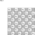
- each rectangle schematically represents a pixel.
- Each rectangle has a symbol indicating the type of color filter (color light output from each pixel). For example, “R” is assigned to R (Red) pixels, “G” is assigned to G (Green) pixels, and “B” is assigned to B (Blue) pixels. The same applies to the following description.
- the arrangement of the R pixel, the G pixel, and the B pixel is repeated in units of 4 ⁇ 4 in the vertical and horizontal directions.
- the 2 ⁇ 2 four pixels at the upper left are all R pixels.
- These 2 ⁇ 2 R pixels are defined as R blocks.
- All 4 pixels of 2 ⁇ 2 adjacent to the right side of the 4-pixel R block are G pixels (referred to as G blocks).
- the lower 2 ⁇ 2 4 pixels of the R block are all G pixels (G block). All 2 ⁇ 2 4 pixels on the lower right side of the R block are B pixels (referred to as B blocks). In this way, all the 2 ⁇ 2 4 pixels have the same color, and the R block, G block, G block, and B block in units of 4 pixels are arranged in the 4 ⁇ 4 pixel region.
- the R pixel, the G pixel, the G pixel, and the B pixel are configured in 4 ⁇ 4 units each including four pixels.
- such an arrangement of pixels is appropriately described as a four-divided Bayer RGB arrangement.
- RGB pixels are arranged, but a configuration including W (White) pixels is also possible.
- W White pixels
- present technology can be applied to a combination of cyan, magenta, and yellow instead of RGB.
- the W pixel When the W pixel is included, the W pixel functions as a spectral sensitivity pixel having total color matching, and the R pixel, the G pixel, and the B pixel are spectral sensitivity pixels having characteristics in their respective colors. Function.
- the present technology can also be applied to an image sensor (image sensor) in which pixels of four types of spectral sensitivities including spectral sensitivities having total color matching are arranged on an imaging surface.
- one unit composed of 4 ⁇ 4 four blocks are included in one unit composed of 4 ⁇ 4, and two of them are G blocks.
- One of the two G blocks may be a W block in which W pixels are arranged.
- the four pixels included in one block have the same color, but two types of exposure times are set.
- Four pixels included in one block are set as long exposure pixels L or short exposure pixels S, respectively.
- the relationship of exposure time is as shown below. Long exposure L> Short exposure S
- the pixel arrangement focusing on the exposure time will be described.
- the R pixels located at the upper left and lower right in the R block are long-time exposure pixels L.
- the R pixel set as the long-time exposure pixel L is described as an RL pixel.
- the pixels set as the long-time exposure pixel L are described as a GL pixel and a BL pixel, respectively.
- the R pixels located at the upper right and lower left in the R block are the short-time exposure pixels S.
- the R pixel set as the short-time exposure pixel S is described as an RS pixel.
- the pixels set as the short-time exposure pixel S are described as a GS pixel and a BS pixel, respectively.
- G pixels located at the upper left and lower right in the G block are GL pixels set as long exposure pixels L, and G pixels located at the upper right and lower left are set as short exposure pixels S. GS pixel.
- B pixels located at the upper left and lower right in the B block are BL pixels set as long exposure pixels L, and B pixels located at the upper right and lower left are set as short exposure pixels S. This is the BS pixel.
- the arrangement of the pixels to which the present technology is applied is that the same color pixels are arranged as four blocks of 2 ⁇ 2 pixels, and the four pixels of the same color in one block are pixels that are photographed with long exposure. It is set for each pixel for which shooting is performed with short-time exposure.
- one block is described as an example in which the vertical and horizontal are M ⁇ M and the number of pixels in the vertical and horizontal directions is the same, but the vertical and horizontal are M ⁇ N, The present technology can be applied even when the number of pixels in the vertical direction and the horizontal direction is different.
- the long exposure pixel L and the short exposure pixel S are arranged according to the number of pixels in one block.
- the arrangement of pixels with different exposure times shown in FIG. 2 is an example, and other arrangements may be used.
- the long-time exposure pixels L are arranged at the upper left and lower right, but other arrangements such as the long-time exposure pixels L at the upper right and lower left may be used.
- the arrangement of the pixels having different exposure times in the R block, the G block, and the B block has been described as being the same, the arrangement may be different for each color.
- different exposures in the R block, the G block, and the B block are arranged such that the long exposure pixel L in the R block and the long exposure pixel L in the G block located on the right are adjacent to each other.
- the arrangement of the temporal pixels may be the same or different.
- the long exposure pixel and the short exposure pixel are set for each pixel included in one photographed image, and the synthesis process (blend) between these pixels is performed.
- an HDR image is generated.
- This exposure time control is performed under the control of the control unit 105.
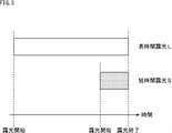
- Fig. 3 shows an example of the timing of exposure time for each pixel.
- the long exposure pixel L is subjected to a long exposure process.
- the short exposure pixel S is subjected to a short exposure process.
- the exposure start timings of the short-time exposure pixels S and the long-time exposure pixels L do not match, but the exposure times are controlled so that the exposure end timings match.
- a process performed by the image processing unit 103 that processes a signal from the image sensor 102 in which the short-time exposure pixels S and the long-time exposure pixels L are arranged as described above will be described.
- an outline of processing performed by the image processing unit 103 will be described, and details will be described later. As an explanation to be described later, there is a process for suppressing the occurrence of false color due to the aliasing component.
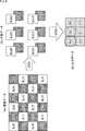
- FIG. 4 shows a processing example when the exposure time is changed in an oblique direction in a four-divided Bayer RGB array.
- FIG. 4 shows the following three data.
- the imaging data is imaging data of the imaging device, and shows an image taken when the exposure time is changed for each column in the Bayer array.
- the white portion indicates the long-time exposure pixel L
- the dark gray portion indicates the short-time exposure pixel S.
- RL00 is the long-time exposure pixel L of the R pixel at the coordinate position (0, 0).
- GL20 is the long-time exposure pixel L of the G pixel at the coordinate position (2, 0).
- the coordinates are shown in a format such as GSxy, GLxy, etc. by applying coordinates (x, y) where x is the vertical downward direction and y is the horizontal right direction.
- the long exposure pixels L and the short exposure pixels S are alternately set in an oblique direction.
- Imaging data indicates a 4 ⁇ 6 pixel area.
- Intermediate data indicates intermediate data generated based on 4 ⁇ 6 (4a) imaging data.
- step S1 (STEP 1), 12 pieces of intermediate pixel data are calculated based on 4 ⁇ 6 (4a) imaging data.
- Output data indicates output data generated based on 12 (4b) intermediate pixel data. This output data is output data generated as a wide dynamic range image.
- Step 1 The process of generating (4b) intermediate data from (4a) imaging data in step S1 is performed by the following diagonal addition process of a plurality of pixel values.
- the pixel value of RLA00 (RLA00) and the pixel value of RSA00 (RSA00) calculated from the R block shown in FIG. 4 (4b) are the values obtained by applying pixel values of a plurality of pixels included in (4a) imaging data. It is calculated by the diagonal addition process according to the equation.
- RLA00 (RL00 + RL11) / 2
- RSA00 (RS01 + RS10) / 2 (1)
- the average value of the RL pixels arranged in the diagonal direction in the R block is calculated, and the average value of the RS pixels is calculated, so that intermediate data is generated.
- a value obtained by adding pixel values may be used as it is.
- intermediate data is generated by calculating the average value of the pixel values of the long-time exposure pixels L and the average value of the pixel values of the short-time exposure pixels S arranged in an oblique direction. Is done.
- DLA represents the average value of the pixel values of the long-time exposure pixels L in one block
- DSA represents the average value of the pixel values of the short-time exposure pixels S in one block
- DL represents one pixel value of the two long-time exposure pixels L in one block
- Dl represents the other pixel value
- DS represents one pixel value of the two short-time exposure pixels S in one block
- Ds represents the other pixel value.
- Step 2 Output data generation processing from (4b) intermediate data in step S2 is performed by (4b) blend processing of pixel values included in the intermediate data as follows.
- the pixel value (R00) of the R00 pixel shown in FIG. 4 (4c) is calculated according to the following calculation formula (1) to which the pixel value of a plurality of pixels included in the intermediate data (4b) and the blend coefficient ⁇ are applied. Is done.
- R00 (1- ⁇ ) ⁇ RSA00 ⁇ Gain + ⁇ ⁇ RLA00 (3)
- Gain Gain multiplied by the pixel value of the short-time exposure pixel (exposure ratio between the long-time exposure pixel and the short-time exposure pixel)
- ⁇ The blend coefficient of the pixel value of the long exposure pixel and the pixel value of the short exposure pixel.
- output data is generated in the G pixel and B pixel in accordance with a calculation formula using a gain and a blend coefficient.
- the R pixel, the G pixel, and the B pixel have different sensitivities, and therefore, for example, different values may be used for the R pixel, the G pixel, and the B pixel for the gain and the blend coefficient.
- the following expression (4) is obtained by expressing the expression (3) as an expression common to the R pixel, the G pixel, and the B pixel.
- DH (1 ⁇ ) ⁇ DS + ⁇ ⁇ DL (4)
- DH represents a pixel value of a predetermined pixel in the HDR image.
- DS corresponds to RSA00 ⁇ GAIN in equation (3).
- FIG. 5A shows an example of the blend processing configuration.
- blur information is measured based on both the short-time exposure image and the long-time exposure image
- the blend coefficient is calculated based on the measured blur information and both the short-time exposure image and the long-time exposure image.
- “Blur” can be defined as a shift in the pixel value of the pixel at the corresponding pixel position between the long-exposure image and the short-exposure image that have been corrected based on the exposure ratio, and “blur information” It can be set as an index value indicating the degree of occurrence of blur corresponding to the shift amount of the pixel value.
- “Blur information” for each pixel is acquired from the captured image, and the blending coefficient determined based on the acquired “blur information” is applied to execute the blending process between the short exposure image and the long exposure image. , An HDR image is generated.
- the blend coefficient ⁇ in consideration of blur is calculated according to the following equation (5), for example.
- max (a, b) a function for obtaining the maximum value of a and b.
- min (a, b) a function for obtaining the minimum value of a and b.
- K 1 and k 0 are parameters. Details will be described later.
- M ( ⁇ L ⁇ S) 2 (6)
- ⁇ L and ⁇ S have the following values.
- ⁇ L Ideal pixel value of exposure-corrected long-exposure image obtained when there is no influence of noise (corresponding to DL in equation (4))
- ⁇ S Exposure correction obtained when there is no influence of noise Ideal pixel value of short-exposure image (corresponding to DS in equation (4))
- the blending process is performed by determining such a blending coefficient ⁇ .
- ⁇ is set to preferentially output a pixel value based on a short-exposure image with little blur because ⁇ approaches 0 at a portion where blur is large, and ⁇ is a value equivalent to the conventional method at a portion where blur is small.
- a pixel value corresponding to a predetermined blend coefficient is generated.
- Such processing is realized, and as a result, an HDR image with a good S / N ratio is obtained from a dark part to a bright part in the moving part with less blur in the moving subject part.
- the amount of calculation of the blend coefficient is not so large and can be processed at high speed. For example, it can be applied to HDR image generation processing of moving images.
- Expression (6) is an expression for calculating a value M indicating the magnitude of blur of a long exposure image.
- M ( ⁇ L ⁇ S) 2 (6)
- ⁇ L Pixel value of exposure-corrected long-exposure image
- ⁇ S Pixel value of exposure-corrected short-exposure image
- the exposure correction long-time exposure image ⁇ L is calculated by multiplying the pixel value of the long-time exposure pixel L by 1
- the exposure correction short-time exposure image ⁇ S is calculated as the short-time exposure pixel. It is calculated by multiplying the pixel value of S by 16.
- the exposure correction long-time exposure image ⁇ L and the exposure correction short-time exposure image ⁇ S calculated in this way are images in which the brightness is matched.
- the exposure-corrected long-time exposure image ⁇ L and the exposure-corrected short-time exposure image ⁇ S which are adjusted in brightness in this way, have substantially the same signal value as long as there is no influence of noise.
- blur detection is performed as described above. That is, in Expression (6), if the exposure correction long-time exposure image ⁇ L and the exposure correction short-time exposure image ⁇ S are the same, the value is 0. However, by capturing a moving subject or the like, the exposure correction long-time exposure image ⁇ L is obtained. When a difference occurs between the exposure correction short-exposure image ⁇ S, some value is calculated.
- FIG. 4 In the (4a) imaging data shown in FIG. 4, attention is paid to the BL22 pixel.
- the BL22 pixel is adjacent to the GS21 pixel on the left, the RL11 pixel on the upper left, and the GS12 pixel on the upper left.
- the BL22 pixel is affected by these GS21 pixel, RL11 pixel, and GS12 pixel. That is, the BL22 pixel is easily affected by adjacent different color pixels.
- the BL33 pixel is adjacent to the BS32 pixel on the left, the BL22 pixel on the upper left, and the BS23 pixel on the upper left.
- the BL33 pixel is affected by these BS32 pixel, BL22 pixel, and BS23 pixel.
- the adjacent pixels affected by the BL33 pixel have the same color, and thus the influence is small.
- the BL22 pixel and the BL33 pixel are the long-time exposure pixels L in the same B block, but there is a difference in whether adjacent pixels are the same color or different colors. As described above, there is a possibility that a difference occurs in the signal value. This is considered to be the influence of the color mixture due to the oblique light component.
- Such an influence of the color mixture due to the oblique light component occurs not only in the long-time exposure pixels L in the B block exemplified in the above description.
- the influence of the color mixture due to the oblique light component appears in the short-time exposure pixel S, as described above, when the exposure correction is converted into the short-time exposure image ⁇ S, an exposure ratio, for example, a value of 16 times is obtained. Since the multiplication is performed, the influence becomes large.
- long exposure pixels L and short exposure pixels S are set in one block, the long exposure pixels L are arranged in an oblique direction, and the short exposure pixels S It was set as the structure arrange
- the influence of the color mixture can be suppressed by performing the calculation shown in the equation (2).
- the HDR image is generated by performing the calculation shown in Expression (4) using the signal in which the influence of the color mixture is suppressed.
- the blend coefficient ⁇ in the equation (4) is set as a coefficient for suppressing the occurrence of blur as described above.
- the signal from the long exposure pixel L and the short exposure pixel S are added.
- the difference in the frequency characteristics in the oblique direction is caused by the signal from the signal, and there is a difference in the pixel value of the long-time exposure pixel L and the pixel value of the short-time exposure pixel S whose exposure ratio is corrected even in the region including the oblique high frequency. End up.
- FIG. 1 An example will be described in which an image including a high-frequency signal is taken with the imaging apparatus 100 (FIG. 1) having the pixel arrangement shown in FIG. 2 (FIG. 4).
- FIG. 4 An example will be described in which an image including a high-frequency signal is taken with the imaging apparatus 100 (FIG. 1) having the pixel arrangement shown in FIG. 2 (FIG. 4).
- FIG. 4 Such an image may be acquired.
- the difference between the long exposure image and the short exposure image is 0, so the image represents 0.
- An image of a color for example, a black color in FIG.
- the image shown in FIG. 6 has a white portion (hereinafter referred to as a folding signal), which indicates that there is a portion where a difference occurs between the long-time exposure image and the short-time exposure image. .
- the difference between the long-time exposure image and the short-time exposure image can be calculated by performing the calculation according to the above equation (6). As described above, it is possible to determine whether or not there is an influence (blurring) due to the moving subject based on the calculation result according to Expression (6). That is, if there is a difference between the long exposure image and the short exposure image, it can be determined that the pixel (region) is affected by the moving subject, and if there is no difference, the pixel (region) is not affected by the moving subject. It can be determined that there is.
- the region is influenced by the moving subject based on the above processing. Is treated as an area where blur is likely to occur.
- the signal of the short-time exposure pixel S is likely to contain a noise component, which is higher than the signal of the long-time exposure pixel L.
- the SN ratio is lowered. There is a possibility.
- the processing for suppressing blur and the processing for suppressing the aliasing signal due to the high frequency signal are not the same processing but different processing.
- the high-frequency information in the oblique direction is detected, and the portion where the detection signal is high is that even if there is a difference between the exposure-corrected long-time exposure image ⁇ L and the exposure-corrected short-time exposure image ⁇ S whose exposure ratio is corrected, It is determined that it is due to high frequency, not caused by the influence of moving objects, and by reducing the strength of the long / short difference used to detect the moving object region, it suppresses erroneous determination of moving object region detection. .
- the signal having the reduced aliasing signal of the exposure correction long exposure image ⁇ L and the exposure correction short exposure image ⁇ S is combined so as to be selectively strongly combined.
- the folding signal is reduced.
- the Applicant has obtained an analysis result that the following four conditions are satisfied for a pixel (region) that is affected by a high-frequency component in an oblique direction.
- the influence of the oblique high-frequency component is described as “the influence of the aliasing component”.
- First condition There is a difference between the exposure correction long-time exposure image ⁇ L and the exposure correction short-time exposure image ⁇ S.
- Second condition There is a large difference in saturation between the exposure-corrected long-time exposure image ⁇ L and the exposure-corrected short-time exposure image ⁇ S.
- Third condition a large saturated signal has a green or magenta color.
- Fourth condition When the generated signal is subtracted from the signal in which no aliasing occurs, the difference is generated with the same amplitude in the opposite direction between G and R or G and B.
- the first condition is that there is a difference between the exposure-corrected long-time exposure image ⁇ L and the exposure-corrected short-time exposure image ⁇ S even when a still image is captured as described above.
- the difference is imaged, for example, it means that an image as shown in FIG. 6 is obtained.
- the second condition is that the exposure correction long exposure image ⁇ L and the exposure correction short exposure image ⁇ S are acquired separately, and when the same area is compared, the area affected by the aliasing component is the exposure correction long exposure image. This means that there is a large difference in saturation between ⁇ L and the exposure-corrected short exposure image ⁇ S.
- the hue is the same and the saturation is the same.
- the hue is greatly different, and there is a large difference in saturation. Arise.
- the exposure correction long exposure image ⁇ L and the exposure correction short exposure image ⁇ S are acquired separately and the same area is compared, the exposure correction long exposure image ⁇ L or exposure correction is obtained.
- a folding signal is generated in one of the short-time exposure images ⁇ S. Therefore, when the exposure correction long exposure image ⁇ L and the exposure correction short exposure image ⁇ S are compared, if a folding signal is generated in one of the images, the exposure correction long exposure is performed in an area where the folding signal is present. A difference is generated between the image ⁇ L and the exposure correction short-time exposure image ⁇ S.
- the third condition is that a large saturation signal has a green or magenta color.
- the influence is an image having a color of green or magenta.
- FIG. 7 shows pixels (signals) in a region affected by the folding signal.
- FIG. 7A shows the pixel arrangement, which is basically the same as the pixel arrangement shown in FIG. 2, but is shown in an obliquely inclined state in order to illustrate pixels to be added diagonally in the horizontal direction. It is shown.
- B of FIG. 7 represents the result of the diagonal addition of the same color.
- C of FIG. 7 represents the addition result (long livestock addition result) of the long exposure pixel L.
- D of FIG. 7 represents the addition result (short livestock addition result) of the short-time exposure pixels S.
- E of FIG. 7 represents a result when the difference between the long stock addition result and the short stock addition result is calculated.
- F of FIG. 7 represents the result of correcting the difference result shown in E of FIG. 7 in consideration of the sensitivity ratio.
- the pixel values of the long-time exposure pixels L in one block are calculated by adding the pixel values of the long-time exposure pixels L arranged in an oblique direction in one block.
- the pixel values of the short-time exposure pixels S are calculated by adding the pixel values of the short-time exposure pixels S to each other.
- FIG. 7C and FIG. 7D illustrate the G pixel and the R pixel.
- C in FIG. 7 represents the G pixel and R pixel of the long-time exposure pixel L diagonally added
- D in FIG. 7 represents the G pixel and R pixel of the short-time exposure pixel S diagonally added.
- FIG. 7E shows the difference (Gg) between the G pixel of the long stock addition result of FIG. 7C and the G pixel of the short stock addition result of FIG. 7D. Further, E in FIG. 7 represents the difference (R ⁇ r) between the R pixel of the long stock addition result of C in FIG. 7 and the R pixel of the short stock addition result of D in FIG.
- a predetermined gain is applied to the signal of the R pixel. Need to be multiplied. Such processing is performed as white balance adjustment in a general imaging apparatus.
- the signal intensity obtained by multiplying the R pixel difference (R ⁇ r) shown in E of FIG. 7 by a predetermined gain to match the sensitivity is shown in F of FIG.
- the adjusted R pixel difference (R ⁇ r) and the G pixel difference (G ⁇ g) have substantially the same signal intensity and are in the opposite directions.
- the R pixel has been described as an example, but the same applies to the B pixel. That is, within the region affected by the aliasing signal, the difference (B ⁇ b) between the B pixels after sensitivity adjustment and the difference (G ⁇ g) between the G pixels have substantially the same signal intensity and are in the opposite directions.
- the fourth condition is that if the generated signal is subtracted from the signal that does not cause aliasing, the difference However, G and R or G and B are generated with the same amplitude in the opposite directions. " Natural signals tend to satisfy the fourth condition.
- a pixel (region) that satisfies all of the first to fourth conditions is a pixel that is affected by the aliasing component.
- FIG. 8 is a diagram illustrating a configuration of the HDR image generation unit 200.
- the HDR image generation unit 200 illustrated in FIG. 8 includes an RGB interpolation signal generation unit 211, an exposure correction unit 212, an SN maximization synthesis ratio calculation unit 213, a aliasing reduction synthesis ratio calculation unit 214, a blur reduction synthesis ratio calculation unit 215,
- the long-lived saturation-considering synthesis ratio calculation unit 216, the long / short synthesis processing unit 217, the aliasing component detection unit 218, the moving object detection unit 219, and the noise reduction processing unit 220 are included.
- the HDR image generation unit 200 receives a signal from the long exposure pixel L and a signal from the short exposure pixel S from the image sensor 102.
- the input signal is a signal after the diagonal addition of the same color and is a signal that has been subjected to the color mixture reduction process.
- the RGB interpolation signal generation unit 211 interpolates signals of R pixels, G pixels, and B pixels that have been exposed for a long time at all pixel positions, and generates a long exposure image that includes R pixels and a long time that includes G pixels. An exposure image and a long exposure image composed of B pixels are generated.
- the RGB interpolation signal generation unit 211 interpolates signals of R pixels, G pixels, and B pixels that have been exposed to a short time at all pixel positions, and includes a short exposure image that includes R pixels and a G pixel. A short-time exposure image and a short-time exposure image composed of B pixels are generated. Each of these generated images is supplied to the exposure correction unit 212.
- the exposure correction unit 212 performs correction to absorb the difference in sensitivity between the R pixel, the G pixel, and the B pixel. As described above, since the G pixel has higher sensitivity than the R pixel and the B pixel, exposure correction is performed by multiplying the R pixel signal and the B pixel signal by respective predetermined gains.
- the exposure correction unit 212 generates a signal for the long exposure pixel L (hereinafter referred to as a long exposure signal) and a signal for the short exposure pixel S (hereinafter described as a short exposure signal).
- a long exposure signal for the R pixel a long exposure signal for the G pixel, a long exposure signal for the B pixel, a short exposure signal for the R pixel, a short exposure signal for the G pixel, and a B pixel
- the short exposure signal is output.
- the long-time exposure signals for R, G, and B from the exposure correction unit 212 and the short-time exposure signals for R, G, and B are respectively converted into an SN maximizing synthesis ratio calculation unit 213, an aliasing component detection unit 218, And supplied to the moving object detection unit 219. Further, the long-time exposure signal from the exposure correction unit 212 is also supplied to the long-lived saturation-considering synthesis ratio calculation unit 216 and the long / short synthesis processing unit 217. The short-time exposure signal from the exposure correction unit 212 is also supplied to the noise reduction processing unit 220.
- the SN maximized combination ratio calculation unit 213 calculates a combination ratio that maximizes the SN ratio, and supplies the SN maximized combination ratio to the aliasing reduction combination ratio calculation unit 214.
- the aliasing reduction synthesis ratio calculation unit 214 corrects the SN maximization synthesis ratio based on the aliasing component information from the aliasing component detection unit 218.
- the configuration and processing of the aliasing component detection unit 218 will be described later with reference to FIG.
- the aliasing component information is information obtained by determining whether or not the first to fourth conditions described above are satisfied, and is information indicating whether or not the pixel is influenced by the aliasing signal. is there.
- the folding signal is generated on the long exposure signal side, the folding signal is not generated on the short exposure signal side. Further, if the folding signal is generated on the short exposure signal side, the folding signal is not generated on the long exposure signal side.
- the reduced synthesis ratio calculation unit 214 calculates a synthesis ratio.
- A ⁇ SN maximization composite ratio ⁇ (1.0 ⁇ short accumulation folding component) ⁇ + (1.0 ⁇ short accumulation folding component)
- OUT ⁇ A ⁇ (1.0-long animal folding component) ⁇ + (0.0 ⁇ long animal folding component)
- the short accumulation folding component and the long stock folding component are information supplied from the folding component detection unit 218 as folding component information.
- an operation for selectively bringing the SN maximal composite ratio close to 1.0 (uses 100% long exposure signal) or 0.0 (uses 100% short exposure signal) is performed using the aliasing component. .
- the aliasing reduction composition ratio calculated in this way is supplied to the blur reduction composition ratio calculation unit 215.
- the blur reduction composition ratio calculation unit 215 calculates a composition ratio for suppressing blur as described above in ⁇ About occurrence of blur>. Specifically, the blend coefficient ⁇ is calculated by the calculation as described above.
- the blur reduction synthesis ratio calculation unit 215 selectively selects the folding reduction synthesis ratio supplied from the folding reduction synthesis ratio calculation unit 214 using the moving object detection information supplied from the moving object detection unit 219. Calculation is performed so as to approach 100 (use 100% long exposure signal) or 0.0 (use 100% short exposure signal).
- the blur reduction composition ratio calculation unit 215 is supplied with moving object detection information indicating whether a moving object is detected from the moving object detection unit 219, that is, whether a pixel is likely to cause blur.
- the animal body detection unit 219 is supplied with the folding component information from the folding component detection unit 218.
- the moving object detection unit 219 assumes that the detected component is not a moving object but a folded component even if it is detected as a moving object.
- the information that the moving object is not detected is supplied to the blur reduction composition ratio calculation unit 215. Therefore, it is possible for the blur reduction composition ratio calculation unit 215 to perform control so as not to execute the process for reducing the blur for the pixel in which the aliasing component is generated.
- the folding component information output from the folding component detection unit 218 may be, for example, 0 or 1 information indicating whether or not the folding component is generated, or the folding component is generated. For example, it may be information having a value of 0 to 1 that represents the likelihood of being unclear.
- the moving object detection information output from the moving object detection unit 219 may be, for example, 0 or 1 information indicating whether or not blur has occurred due to the influence of the moving object. It may be information having a value of 0 to 1, for example, representing the certainty of the possibility of being.
- the processing up to this point suppresses color mixing, suppresses false colors that may occur due to the effects of aliasing components, and suppresses blurs that may occur due to effects of moving objects.
- the blur reduction composition ratio from the blur reduction composition ratio calculation unit 215 is supplied to the long livestock saturation consideration composition ratio calculation unit 216.
- the long-lived saturation-considering composition ratio calculation unit 216 refers to the long-time exposure signal supplied from the exposure correction unit 212 and determines whether or not the long-time exposure pixel L is saturated.
- the pixel value (signal) of the saturated pixel is not used, and for the saturated pixel, the supplied blur reduction composition ratio is converted to a ratio that uses the pixel value (signal) of the short-time exposure pixel S. To do.
- the long-lived saturation-considering composition ratio calculation unit 216 comprehensively synthesizes a ratio (0.0 (uses 100% short-time exposure signal)) that uses a short-time exposure signal instead of a long-time exposure signal for saturated pixels.
- the ratio is output to the subsequent long / short synthesis processing unit 217 as the ratio, and for the pixels that are not saturated, the input blur reduction synthesis ratio is output to the subsequent long / short synthesis processing unit 217 as the total synthesis ratio.
- the total synthesis ratio is a synthesis ratio that maximizes the S / N ratio in the flat part, and is a synthesis ratio that reduces the strength if the area is the aliasing component.
- the composition ratio is reduced.
- the long / short synthesis processing unit 217 is supplied with the long time exposure signal from the exposure correction unit 212 and the short time exposure signal via the noise reduction processing unit 220.
- the short exposure signal is supplied to the long / short combination processing unit 217 after noise is reduced by the noise reduction processing unit 220.
- the long / short combination processing unit 217 combines the supplied long-time exposure signal and short-time exposure signal based on the total combination ratio from the long-lived saturation consideration component ratio calculation unit 216.
- the signal synthesized in this way is output as an HDR image signal.
- the configuration of the aliasing component detection unit 218 of the HDR image generation unit 200 is shown in FIG.
- the aliasing component detection unit 218 detects the aliasing component by determining whether or not the first to fourth conditions are satisfied.
- the aliasing component detection unit 218 includes a strong saturation generation region detection unit 251, a local color ratio calculation unit 252, each color length difference calculation unit 253, each color length difference difference normalization unit 254, and a normalized amplitude intensity similarity calculation unit 255. It is said that.
- the folding component detection unit 218 is supplied with a long exposure signal and a short exposure signal from the exposure correction unit 212 (FIG. 8). Since the long exposure signal and the short exposure signal include an R signal, a G signal, and a B signal, respectively, six-color signals are supplied to the aliasing component detection unit 218.
- the intense saturation generation area detection unit 251 is a part that mainly determines whether or not the area (pixel) satisfies the second condition and the third condition.
- the strong saturation generation area detection unit 251 performs conversion to a color space, detection of a saturation difference, and detection of a specific color.
- the intense saturation generation area detection unit 251 converts the supplied long exposure signal and short exposure signal into color spaces, respectively. For example, the image is transferred to a color space such as a Lab color space, and saturation and color difference are obtained to determine whether the color is a specific color.
- the second condition is that there is a large difference in saturation between the exposure correction long exposure image ⁇ L and the exposure correction short exposure image ⁇ S. It is determined whether or not.
- a signal with a large saturation has a green or magenta color
- This determination result (determination result E) is supplied to the local color ratio calculation unit 252 and the normalized amplitude intensity similarity calculation unit 255.
- each color length difference calculating unit 253 determines the exposure correction long exposure image ⁇ L for each of the R signal, the G signal, and the B signal. The difference from the exposure corrected short exposure image ⁇ S is calculated.
- each color length short / difference calculating unit 253 divides the calculated difference using a signal with lower saturation in order to perform normalization.
- the signal having the lower saturation is a signal having a lower saturation when the saturation of the long-time exposure signal and the saturation of the short-time exposure signal are compared. Further, as described above, it can be determined that the signal with the lower saturation is the signal on the side where the aliasing component does not appear. That is, here, a long-time exposure signal or a short-time exposure signal with no aliasing component is selected, and normalization of the long-short difference is performed.
- Each color length difference calculation unit 253 obtains a difference between the exposure-corrected long-time exposure image ⁇ L and the exposure-correction short-time exposure image ⁇ S for each of the R signal, the G signal, and the B signal, Each of the lower R signal, G signal, and B signal is divided to generate a standardized long / short difference signal, which is output to each subsequent color length / short difference normalization unit 254.
- the first condition that is, the condition that “the difference occurs between the exposure-corrected long-time exposure image ⁇ L and the exposure-corrected short-time exposure image ⁇ S”. Is satisfied.
- the long / short difference signal does not have a predetermined value, it can be determined that the first condition is not satisfied. In such a case, the long / short difference signal is processed as 0 in the subsequent processing. Therefore, as a result, the folding component information becomes a determination result that the folding component is not detected.
- the difference between the exposure-corrected long-exposure image ⁇ L and the exposure-corrected short-exposure image ⁇ S is affected by noise, and there is a possibility that the difference may be calculated even if there is no difference.
- a predetermined threshold is provided, and it is determined whether or not the difference between the exposure-corrected long-time exposure image ⁇ L and the exposure-corrected short-time exposure image ⁇ S is equal to or larger than the predetermined threshold. In this case, it may be determined that the first condition is satisfied.
- the local color ratio calculation unit 252 obtains a local color ratio using a signal with lower saturation.
- the local color ratio calculation unit 252 refers to the determination result E from the strong saturation generation region detection unit 251 to determine the signal with the lower saturation, and based on the determination, the supplied exposure correction long time
- the signal of the exposure image ⁇ L or the signal of the exposure corrected short-time exposure image ⁇ S is selected, and the local color ratio is obtained.
- the obtained local color ratios of R, G, and B are supplied to each color length difference difference normalizing unit 254.
- Each color length difference difference normalizing unit 254 multiplies each of the R, G, and B difference signals from each color length difference calculating unit 253 by the local ratio of each of R, G, and B from the local color ratio calculating unit 252.
- the RGB color levels are aligned to generate a standardized R component long / short difference signal, a standardized G component long / short difference signal, and a standardized B component long / short difference signal, respectively.
- Each color length difference standardization unit 254 unifies the RB value by selecting the larger normalized value of the normalized R component length difference signal or the B component length difference signal, The selected R component or B component long / short difference signal is supplied to the normalized amplitude intensity similarity calculation unit 255.
- Each color length difference normalization unit 254 supplies the normalized G component length difference signal to the normalized amplitude intensity similarity calculation unit 255.
- the standardized amplitude intensity similarity calculation unit 255 calculates the similarity between the supplied standardized G component long / short difference signal, the standardized R (or B) component long / short difference signal, and the sign direction. Is evaluated, and it is determined whether or not both signals have the same amplitude by the inverse method. This determination is the determination described with reference to FIG. 7 and is a determination as to whether or not the fourth condition is satisfied.
- the normalized amplitude intensity similarity calculation unit 255 determines whether or not the fourth condition is satisfied.
- the standardized amplitude intensity similarity calculation unit 255 is also supplied with the determination result E from the strong saturation generation region detection unit 251.
- This determination result E is information including a determination result as to whether or not the second condition and the third condition are satisfied.
- the normalized amplitude intensity similarity calculation unit 255 determines that the fourth condition is satisfied, and the supplied determination result E also indicates a result determined to satisfy the second and third conditions, If the region (pixel) to be processed is a region where a aliasing component is generated, a final determination is made, and the determination result is used as aliasing component information to determine the aliasing reduction combination ratio calculation unit 214 and the animal. It supplies to the body detection part 219 (FIG. 8).
- the folding component information output from the folding component detection unit 218 may be, for example, 0 or 1 information indicating whether or not the folding component is generated.
- it may be information having a value of 0 to 1 that represents the probability of occurrence of a component.
- the process for the region (pixel) to be processed is terminated.
- information indicating that there is no folding component may be output as the folding component information.
- the local color ratio calculation unit 252 each color length difference calculation unit 253, The processing in each color length difference normalization unit 254 may not be performed, and the standardized amplitude intensity similarity calculation unit 255 may output information indicating that there is no aliasing component.
- the folded component detection unit 218 can detect a region where the folded component is generated.
- the aliasing component As described above, it is possible to detect a region where the aliasing component is generated, so that it is a region where a difference between the long-time exposure signal and the short-time exposure signal whose exposure ratio is corrected occurs. However, it is possible to perform a process of weakening the signal value of the difference at a place where the detection strength of the aliasing component is high. By enabling such processing, it is possible to prevent erroneous detection of the moving object.
- a composite ratio that maximizes the S / N ratio is obtained, and if it is a folded area, a composite ratio that reduces the strength is adopted (in a four-part Bayer array, a right diagonal pattern and a left diagonal pattern are used.
- an optimum combining ratio can be calculated by adopting a combining ratio that reduces blur (moving object blur).
- the adjacent 2 ⁇ 2 pixels are set to the same color filter, and the 2 ⁇ 2 color filter is used with an imaging element using a four-divided Bayer type array arranged in a Bayer type.
- the effects of color mixing are alleviated, blurring of moving objects, suppression of aliasing signals due to high-frequency signals, optimization of SN, saturation of long-time exposure signals Can be obtained.
- FIG. 10 is a diagram illustrating a usage example in which the above-described imaging device and an electronic apparatus including the imaging device are used.
- the imaging device described above can be used in various cases for sensing light such as visible light, infrared light, ultraviolet light, and X-rays as follows.
- Devices for taking images for viewing such as digital cameras and mobile devices with camera functions
- Devices used for traffic such as in-vehicle sensors that capture the back, surroundings, and interiors of vehicles, surveillance cameras that monitor traveling vehicles and roads, and ranging sensors that measure distances between vehicles, etc.
- Equipment used for home appliances such as TVs, refrigerators, air conditioners, etc. to take pictures and operate the equipment according to the gestures ⁇ Endoscopes, equipment that performs blood vessel photography by receiving infrared light, etc.
- Equipment used for medical and health care ⁇ Security equipment such as security surveillance cameras and personal authentication cameras ⁇ Skin measuring instrument for photographing skin and scalp photography Such as a microscope to do beauty Equipment used for sports-Equipment used for sports such as action cameras and wearable cameras for sports applications-Used for agriculture such as cameras for monitoring the condition of fields and crops apparatus
- the series of processes described above can be executed by hardware or can be executed by software.
- a program constituting the software is installed in the computer.
- the computer includes, for example, a general-purpose personal computer capable of executing various functions by installing various programs by installing a computer incorporated in dedicated hardware.
- FIG. 11 is a block diagram showing an example of the hardware configuration of a computer that executes the above-described series of processing by a program.
- a CPU Central Processing Unit
- ROM Read Only Memory
- RAM Random Access Memory
- An input / output interface 305 is further connected to the bus 304.
- An input unit 306, an output unit 307, a storage unit 308, a communication unit 309, and a drive 310 are connected to the input / output interface 305.
- the input unit 306 includes a keyboard, a mouse, a microphone, and the like.
- the output unit 307 includes a display, a speaker, and the like.
- the storage unit 308 includes a hard disk, a nonvolatile memory, and the like.
- the communication unit 309 includes a network interface and the like.
- the drive 310 drives a removable medium 311 such as a magnetic disk, an optical disk, a magneto-optical disk, or a semiconductor memory.
- the CPU 301 loads the program stored in the storage unit 308 to the RAM 303 via the input / output interface 305 and the bus 304 and executes the program, for example. Is performed.
- the program executed by the computer (CPU 301) can be provided by being recorded in, for example, a removable medium 311 as a package medium or the like.
- the program can be provided via a wired or wireless transmission medium such as a local area network, the Internet, or digital satellite broadcasting.
- the program can be installed in the storage unit 308 via the input / output interface 305 by attaching the removable medium 311 to the drive 310. Further, the program can be received by the communication unit 309 via a wired or wireless transmission medium and installed in the storage unit 308. In addition, the program can be installed in the ROM 302 or the storage unit 308 in advance.
- the program executed by the computer may be a program that is processed in time series in the order described in this specification, or in parallel or at a necessary timing such as when a call is made. It may be a program for processing.
- system represents the entire apparatus composed of a plurality of apparatuses.
- this technique can also take the following structures.
- a pixel having the same exposure time is disposed in an oblique direction, and includes a processing unit that processes a signal from the pixel disposed on the imaging surface in the block unit,
- the processor is A generating unit that generates a long-time exposure image by adding signals from the long-time exposure pixels in the one block and generates a short-time exposure image by adding signals from the short-time exposure pixels;
- a combining unit that combines the long-time exposure image generated by the generation unit and the short-time exposure image at a predetermined combining ratio; From the difference between the long-time exposure image and the short-time exposure image, an animal body detection unit that detects an animal body, A folding component detection unit for detecting a folding component from the long exposure image and the short exposure image;
- the imaging ratio is set from
- the aliasing component detection unit determines whether or not a difference between the long-time exposure image and the short-time exposure image and a saturation of each of the long-time exposure image and the short-time exposure image satisfy a predetermined condition.
- the aliasing component detection unit detects the aliasing component by determining whether or not the following first to fourth conditions are satisfied.
- First condition long-time exposure image and short-time exposure image
- Second condition There is a difference in saturation between the long-time exposure image and the short-time exposure image
- Third condition A large signal with saturation has a green or magenta color Condition 4: When the generated signal is subtracted from the signal having no aliasing component, the difference is generated with the same amplitude in the reverse direction between the G pixel and the R pixel or the G pixel and the B pixel.
- the composite ratio is the long-time exposure image or the short-time exposure in which it is determined that no aliasing component has occurred in a pixel where the aliasing component is detected by the aliasing component detection unit.
- the imaging apparatus according to any one of (1) to (5), wherein a ratio of using a large amount of images is used.
- the composition ratio is a pixel in which the moving object is detected by the moving object detection unit, but it is determined that no folding component is generated in the pixel in which the folding component is detected by the folding component detection unit.
- the imaging device according to any one of (1) to (6), wherein the ratio is a ratio in which the long-time exposure image or the short-time exposure image is frequently used.
- the pixels having the same exposure time are arranged in an oblique direction and include a processing unit that processes signals from the pixels arranged on the imaging surface in units of the blocks.
- the processor is A long exposure image is generated by adding signals from the long exposure pixels in the block, and a short exposure image is generated by adding signals from the short exposure pixels.
- the generated long exposure image and the short exposure image are synthesized at a predetermined synthesis ratio, From the difference between the long exposure image and the short exposure image, the moving object is detected, Detecting a folded component from the long exposure image and the short exposure image, The imaging ratio is set from the detection result of the moving object in the moving object detection unit and the detection result of the folded component in the folded component detection unit. (9) When 2 ⁇ 2 pixels having the same spectral sensitivity are made into one block, out of 2 ⁇ 2 pixels in the one block, two pixels are long-time exposure pixels, and two pixels are short-time exposure.
- An image pickup apparatus including a processing unit that processes a signal from a pixel that is arranged in an oblique direction and is arranged on the image pickup surface in a block unit.
- the processor is A long exposure image is generated by adding signals from the long exposure pixels in the block, and a short exposure image is generated by adding signals from the short exposure pixels.
- the generated long exposure image and the short exposure image are synthesized at a predetermined synthesis ratio, From the difference between the long exposure image and the short exposure image, the moving object is detected, From the long-time exposure image and the short-time exposure image, to execute a process including a step of detecting a folding component,
- the composition ratio is a program for causing a computer to execute a process set based on the detection result of the moving object in the moving object detection unit and the detection result of the folding component in the folding component detection unit.
- Imaging device 101 optical lens, 102, imaging device, 103 image processing unit, 104 signal processing unit, 105 control unit, 200 HDR image generation unit, 211 RGB interpolation signal generation unit, 212 exposure correction unit, 213 SN maximization synthesis Ratio calculation unit, 214 Folding reduction synthesis ratio calculation unit, 215 Blur reduction synthesis ratio calculation unit, 216 Long livestock saturation consideration synthesis ratio calculation unit, 217 Long and short synthesis processing unit, 218 Folding component detection unit, 219 Animal body detection unit, 220 noise reduction processing unit, 251 strong saturation generation region detection unit, 252 local color ratio calculation unit, 253 each color length short difference calculation unit, 254 each color length short difference normalization unit, 255 standardized amplitude intensity similarity calculation unit
Landscapes
- Engineering & Computer Science (AREA)
- Multimedia (AREA)
- Signal Processing (AREA)
- Studio Devices (AREA)
- Color Television Image Signal Generators (AREA)
- Transforming Light Signals Into Electric Signals (AREA)
Abstract
La présente invention concerne un procédé de capture d'image, un programme, un dispositif de capture d'image configurés pour permettre d'améliorer la qualité d'image. La présente invention comporte un processeur de telle sorte que, lorsqu'un réseau 2x2 de pixels ayant la même sensibilité spectrale est défini comme étant un bloc, deux pixels dans le bloc sont des pixels à longue exposition, deux pixels sont des pixels à courte exposition, des pixels ayant le même temps d'exposition sont disposés en diagonale, et des signaux provenant de pixels disposés sur la surface de la capture d'image sont traités dans des unités de bloc. Le processeur : ajoute des signaux provenant des pixels à longue exposition dans le bloc pour générer une image à longue exposition ; ajoute des signaux provenant des pixels à courte exposition pour générer une image à courte exposition ; synthétise l'image à longue exposition et l'image à courte exposition résultantes à un rapport de synthèse prescrit ; détecte un corps mobile sur la base de la différence entre l'image à longue exposition et l'image à courte exposition ; et détecte un élément de pliage sur la base de l'image à longue exposition et de l'image à courte exposition. Le rapport de synthèse est réglé sur la base du résultat de détection du corps mobile et du résultat de détection de l'élément de pliage.
Applications Claiming Priority (2)
| Application Number | Priority Date | Filing Date | Title |
|---|---|---|---|
| JP2015-081666 | 2015-04-13 | ||
| JP2015081666A JP2016201733A (ja) | 2015-04-13 | 2015-04-13 | 撮像装置、撮像方法、並びにプログラム |
Publications (1)
| Publication Number | Publication Date |
|---|---|
| WO2016167140A1 true WO2016167140A1 (fr) | 2016-10-20 |
Family
ID=57127239
Family Applications (1)
| Application Number | Title | Priority Date | Filing Date |
|---|---|---|---|
| PCT/JP2016/060897 Ceased WO2016167140A1 (fr) | 2015-04-13 | 2016-04-01 | Dispositif de capture d'image, procédé de capture d'image et programme |
Country Status (2)
| Country | Link |
|---|---|
| JP (1) | JP2016201733A (fr) |
| WO (1) | WO2016167140A1 (fr) |
Cited By (3)
| Publication number | Priority date | Publication date | Assignee | Title |
|---|---|---|---|---|
| CN113658128A (zh) * | 2021-08-13 | 2021-11-16 | Oppo广东移动通信有限公司 | 图像模糊程度确定方法、数据集构建方法与去模糊方法 |
| EP3917138A1 (fr) * | 2020-05-29 | 2021-12-01 | Canon Kabushiki Kaisha | Appareil et procédé de codage, appareil de capture d'images et support d'enregistrement |
| CN119893318A (zh) * | 2025-01-06 | 2025-04-25 | 维沃移动通信有限公司 | 图像处理方法、装置、设备及介质 |
Families Citing this family (3)
| Publication number | Priority date | Publication date | Assignee | Title |
|---|---|---|---|---|
| WO2020210472A1 (fr) | 2019-04-11 | 2020-10-15 | Dolby Laboratories Licensing Corporation | Génération d'image à plage dynamique élevée avec débruitage à pré-combinaison |
| JP7497216B2 (ja) * | 2020-05-29 | 2024-06-10 | キヤノン株式会社 | 画像処理装置及び方法、撮像装置、プログラム、記憶媒体 |
| WO2026034214A1 (fr) * | 2024-08-09 | 2026-02-12 | ソニーセミコンダクタソリューションズ株式会社 | Dispositif d'imagerie |
Citations (3)
| Publication number | Priority date | Publication date | Assignee | Title |
|---|---|---|---|---|
| JP2013066142A (ja) * | 2011-08-31 | 2013-04-11 | Sony Corp | 画像処理装置、および画像処理方法、並びにプログラム |
| JP2014039170A (ja) * | 2012-08-16 | 2014-02-27 | Sony Corp | 画像処理装置、および画像処理方法、並びにプログラム |
| JP2015033107A (ja) * | 2013-08-07 | 2015-02-16 | ソニー株式会社 | 画像処理装置および画像処理方法、並びに、電子機器 |
-
2015
- 2015-04-13 JP JP2015081666A patent/JP2016201733A/ja active Pending
-
2016
- 2016-04-01 WO PCT/JP2016/060897 patent/WO2016167140A1/fr not_active Ceased
Patent Citations (3)
| Publication number | Priority date | Publication date | Assignee | Title |
|---|---|---|---|---|
| JP2013066142A (ja) * | 2011-08-31 | 2013-04-11 | Sony Corp | 画像処理装置、および画像処理方法、並びにプログラム |
| JP2014039170A (ja) * | 2012-08-16 | 2014-02-27 | Sony Corp | 画像処理装置、および画像処理方法、並びにプログラム |
| JP2015033107A (ja) * | 2013-08-07 | 2015-02-16 | ソニー株式会社 | 画像処理装置および画像処理方法、並びに、電子機器 |
Cited By (6)
| Publication number | Priority date | Publication date | Assignee | Title |
|---|---|---|---|---|
| EP3917138A1 (fr) * | 2020-05-29 | 2021-12-01 | Canon Kabushiki Kaisha | Appareil et procédé de codage, appareil de capture d'images et support d'enregistrement |
| CN113747152A (zh) * | 2020-05-29 | 2021-12-03 | 佳能株式会社 | 编码装置和方法、图像捕获装置以及存储介质 |
| US11483497B2 (en) | 2020-05-29 | 2022-10-25 | Canon Kabushiki Kaisha | Encoding apparatus and method, image capture apparatus, and storage medium |
| CN113747152B (zh) * | 2020-05-29 | 2025-05-06 | 佳能株式会社 | 编码装置和方法、图像捕获装置以及存储介质 |
| CN113658128A (zh) * | 2021-08-13 | 2021-11-16 | Oppo广东移动通信有限公司 | 图像模糊程度确定方法、数据集构建方法与去模糊方法 |
| CN119893318A (zh) * | 2025-01-06 | 2025-04-25 | 维沃移动通信有限公司 | 图像处理方法、装置、设备及介质 |
Also Published As
| Publication number | Publication date |
|---|---|
| JP2016201733A (ja) | 2016-12-01 |
Similar Documents
| Publication | Publication Date | Title |
|---|---|---|
| CN112532855B (zh) | 一种图像处理方法和装置 | |
| US8169491B2 (en) | Apparatus and method of obtaining image and apparatus and method of processing image | |
| KR101263888B1 (ko) | 화상처리장치 및 화상처리방법과 컴퓨터·프로그램 | |
| CN104349018B (zh) | 图像处理设备、图像处理方法和电子设备 | |
| CN103248809B (zh) | 图像信号处理装置、摄像装置以及图像处理装置 | |
| CN107534761B (zh) | 成像装置、成像方法、图像处理装置 | |
| WO2016167140A1 (fr) | Dispositif de capture d'image, procédé de capture d'image et programme | |
| JP6312487B2 (ja) | 画像処理装置及びその制御方法、並びに、プログラム | |
| US20180146144A1 (en) | Image processing device, image processing method, program, and imaging device | |
| WO2011151867A1 (fr) | Dispositif d'imagerie, moyens d'imagerie et programme | |
| WO2014027511A1 (fr) | Dispositif de traitement d'image, procédé de traitement d'image et programme | |
| JP5414691B2 (ja) | 画像処理装置及び画像処理方法 | |
| US9589339B2 (en) | Image processing apparatus and control method therefor | |
| WO2017086155A1 (fr) | Dispositif de capture d'images, procédé de capture d'images, et programme | |
| US10944929B2 (en) | Imaging apparatus and imaging method | |
| JP2013162347A (ja) | 画像処理装置、画像処理方法、プログラム、および装置 | |
| WO2017149854A1 (fr) | Appareil de traitement de signal, appareil d'imagerie, et procédé de traitement de signal | |
| JP6800806B2 (ja) | 画像処理装置、画像処理方法およびプログラム | |
| JP2016111568A (ja) | 像ぶれ補正制御装置、撮像装置およびそれらの制御方法、プログラム | |
| JP2016192707A (ja) | 撮像素子、撮像方法、並びにプログラム | |
| JP2011171842A (ja) | 画像処理装置及び画像処理プログラム | |
| JP5245648B2 (ja) | 画像処理装置、及び、プログラム | |
| KR20160030350A (ko) | 화상 처리 장치 및 화상 처리 방법 | |
| JP6700028B2 (ja) | ベクトル算出装置およびベクトル算出方法 | |
| JP2015080157A (ja) | 画像処理装置、画像処理方法及びプログラム |
Legal Events
| Date | Code | Title | Description |
|---|---|---|---|
| 121 | Ep: the epo has been informed by wipo that ep was designated in this application |
Ref document number: 16779931 Country of ref document: EP Kind code of ref document: A1 |
|
| NENP | Non-entry into the national phase |
Ref country code: DE |
|
| 122 | Ep: pct application non-entry in european phase |
Ref document number: 16779931 Country of ref document: EP Kind code of ref document: A1 |