WO2016170734A1 - Dispositif de cuisson - Google Patents
Dispositif de cuisson Download PDFInfo
- Publication number
- WO2016170734A1 WO2016170734A1 PCT/JP2016/001775 JP2016001775W WO2016170734A1 WO 2016170734 A1 WO2016170734 A1 WO 2016170734A1 JP 2016001775 W JP2016001775 W JP 2016001775W WO 2016170734 A1 WO2016170734 A1 WO 2016170734A1
- Authority
- WO
- WIPO (PCT)
- Prior art keywords
- infrared sensor
- temperature distribution
- heating cooker
- temperature
- heated
- Prior art date
- Legal status (The legal status is an assumption and is not a legal conclusion. Google has not performed a legal analysis and makes no representation as to the accuracy of the status listed.)
- Ceased
Links
Images


Classifications
-
- F—MECHANICAL ENGINEERING; LIGHTING; HEATING; WEAPONS; BLASTING
- F24—HEATING; RANGES; VENTILATING
- F24C—DOMESTIC STOVES OR RANGES ; DETAILS OF DOMESTIC STOVES OR RANGES, OF GENERAL APPLICATION
- F24C7/00—Stoves or ranges heated by electric energy
- F24C7/02—Stoves or ranges heated by electric energy using microwaves
Definitions
- the present disclosure relates to a heating cooker that heats an object to be heated.
- the conventional heating cooker has a heating chamber, a high frequency generator, an infrared array sensor, and a control unit.
- Food or food to be heated including food and containers is stored in a heating chamber.
- the high frequency generator generates a high frequency for heating the object to be heated.
- the infrared array sensor detects temperatures at a plurality of locations within a viewing angle including the object to be heated by a plurality of infrared sensor elements arranged in a matrix.
- the control unit controls the heating of the object to be heated by controlling the high frequency generator (Patent Document 1).
- Another conventional heating cooker has a microwave generator, an inverter, a heating chamber, and control means.
- the microwave generator generates microwaves.
- an inverter supplies the electric power required in order to generate a microwave to a microwave generation part.
- the heating chamber accommodates a microwave heating load.
- the control means controls the inverter 8 to vary the power of the microwave generation unit (Patent Document 2).
- the heating cooker includes a microwave generation unit that generates microwaves, a heating chamber for storing an object to be heated, an infrared sensor installed inside the heating chamber, and a scanning unit that scans the infrared sensor. And a control unit that controls the microwave generation unit based on the output of the infrared sensor. Then, the infrared sensor acquires a plurality of temperature distributions by acquiring a temperature distribution each time a predetermined distance is scanned. Further, the control unit controls the microwave generation unit according to the temperature distribution obtained by adding together the plurality of temperature distributions acquired by the infrared sensor.
- the figure which shows the heating cooker of Embodiment 1 of this indication The figure which shows the scanning part of the heating cooker of Embodiment 1 of this indication.
- the heating cooker shown to patent document 1 and patent document 2 can not measure the temperature of a to-be-heated material correctly, when the magnitude
- the heating cooker of the present disclosure can accurately measure the temperature of the object to be heated even if the object to be heated is small or the temperature of part of the object to be heated is locally high.
- Embodiment 1 Below, the heating cooker 1 of Embodiment 1 is demonstrated, using a drawing.
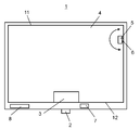
- FIG. 1 shows a heating cooker 1 according to Embodiment 1
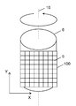
- FIG. 2 shows a scanning unit 6.
- the heating cooker 1 includes a microwave generating unit 2, a heating chamber 4, an infrared sensor 5, a scanning unit 6, a control unit 7, and an inverter 8.
- the microwave generator 2 generates microwaves.
- the heating chamber 4 accommodates the microwave generator 2 and the object to be heated 3 such as food or cloth.
- the infrared sensor 5 is installed on the inner wall of the heating chamber 4.
- the scanning unit 6 scans the infrared sensor 5.
- the controller 7 controls the microwave generator 2.
- the inverter 8 supplies power to the microwave generator 2.
- the microwave generator 2 is supplied with power from the inverter 8.
- the microwave generator 2 generates microwaves of 2450 MHz.
- produces in the microwave generation part 2 is not restricted to 2450 MHz, Another wavelength may be sufficient.
- the microwaves are introduced into the heating chamber 4 via an antenna (not shown).
- the object to be heated 3 is rotated by a rotating table (not shown) provided in the heating chamber 4 to evenly heat the object to be heated 3.
- the present embodiment is configured as described above.
- the present invention is not limited to this configuration, and the antenna may be rotated without providing the rotation table.
- the heating chamber 4 is made of a metal such as aluminum to reduce heating loss.
- An infrared sensor 5 is installed on the inner wall of the heating chamber 4 to detect the temperature of the object 3 in the heating chamber 4.
- the controller 7 is connected to the microwave generator 2, the inverter 8, and the infrared sensor 5.
- the person who operates the heating cooker 1 will be described below as a "user".
- the inverter 8 operates according to the operation of the user. Then, the inverter 8 supplies power to the microwave generation unit 2, and the microwave generation unit 2 generates microwaves.
- the control unit 7 controls the microwave generating unit 2 based on the output of the infrared sensor 5 so that the object 3 to be heated is uniformly heated.
- the heating cooker 1 is controlled such that the object 3 can be heated as the user inputs to the heating cooker 1.
- the infrared sensor 5 has a thermal infrared detection unit in which a temperature sensing unit is embedded.
- a thermoelectric conversion unit is used for the temperature sensing unit.
- the thermoelectric conversion unit is configured of a thermopile that converts thermal energy of infrared rays emitted from the object to be heated 3 into electrical energy.
- the infrared sensor 5 has the infrared detection element 100 (non-contact infrared detection element).
- the infrared detection element 100 is a two-dimensional array in which a ⁇ b pixel units 9 are formed in a two-dimensional array of a rows and b columns on the surface of a semiconductor substrate.
- a and b are integers of 2 or more.
- the pixel unit 9 has a MOS (Metal-Oxide Semiconductor) transistor for extracting the temperature sensitive portion and the output voltage of the temperature sensitive portion.
- MOS Metal-Oxide Semiconductor
- the pixel unit 9 in the first embodiment is configured as an 8 ⁇ 8 pixel unit.
- the pixel units 9 are arranged in the direction of the short axis of the pixel unit 9, and hereinafter, the direction in which the pixel units 9 are arranged will be referred to as a row direction or a column direction.
- the row direction of the pixel unit 9 will be described as the X-axis direction (first direction), and the column direction as the Y-axis direction (second direction).
- the scanning unit 6 is configured by a motor or the like, rotates the infrared sensor around the rotation axis 10, and scans the infrared sensor 5 in a direction connecting the ceiling 11 and the bottom surface 12 of the heating chamber 4.
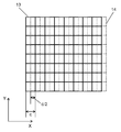
- FIG. 3 shows the detection area 13 of the infrared sensor 5 (shown in FIG. 1) before and after scanning.
- FIG. 4A shows a generated image generated based on the temperature distribution.
- FIG. 4B shows a generated image generated based on a plurality of temperature distributions acquired by scanning an infrared sensor.
- the detection area 13 before scanning is indicated by a solid line
- the detection area 14 after scanning is indicated by a dotted line.
- the dark part shows the measurement image 15 whose measurement has been completed
- the white part shows the unmeasured image 16 whose measurement has not been completed.
- the length of one side of the pixel portion 9 is described as c.
- the temperature distribution of the detection area 13 of the infrared sensor 5 is acquired.
- the infrared sensor 5 is scanned by the length c / 2 in the X-axis direction by the scanning unit 6, and the temperature distribution of the detection area 14 after scanning is acquired.
- the temperature distribution of the detection area 14 after scanning the information between the pixels of the temperature distribution acquired first is acquired.
- the process of scanning the infrared sensor 5 for a length c / 2 and acquiring the temperature distribution is repeated, and the infrared sensor 5 acquires a temperature distribution every time it is scanned by a predetermined distance, and acquires a plurality of temperature distributions. .
- Each temperature distribution is added so that the information between the pixels of the plurality of temperature distributions acquired in this manner is complemented, and the temperature distribution after interpolation is acquired.
- the temperature distribution of the first embodiment is compared with the case where the temperature distribution is obtained by the conventional method using only the temperature distribution obtained by scanning without complementing the temperature distribution.
- the temperature distribution acquired by the method has a doubled measurement image.
- the resolution is doubled because the pixels for which the measurement has been completed are doubled compared to before the temperature distribution is complemented.
- by scanning the infrared sensor 5 and acquiring the temperature distribution after complementation it is possible to acquire a more detailed temperature distribution.
- the temperature data obtained in one pixel unit 9 is the temperature data obtained by averaging the temperature of the object to be heated 3 and the temperature other than the object to be heated 3 such as the background, so the temperature of the object to be heated 3 can be accurately determined. It can not be detected.
- the control unit 7 controls the microwave generation unit 2 according to the high-resolution temperature distribution. Even when the object to be heated 3 is small, the temperature of the object to be heated 3 is not averaged by the temperature of the background other than the object to be heated 3. Therefore, the heating cooker 1 can detect the temperature of the to-be-heated material 3 accurately. The accuracy of the heating control in the heating cooker 1 can be improved.
- heating control can be performed with high accuracy by controlling the microwave generation unit 2 according to the high-resolution temperature distribution.
- the infrared sensor 5 is scanned for a length c / 2, but the distance for scanning the infrared sensor 5 is not limited to this.
- the distance for scanning the infrared sensor 5 may be set to another distance such as c / 4.
- the resolution of the temperature distribution after complementation is four times that in the case where the temperature distribution is not complemented. Therefore, the temperature of the object to be heated 3 can be detected more accurately.
- the distance for scanning the infrared sensor 5 is shortened, the resolution of the temperature distribution after complementation can be improved by shortening the distance.
- the distance for scanning the infrared sensor 5 is c / n, it is possible to acquire a temperature distribution after complementation of n times the resolution compared to the temperature distribution not complemented.
- the distance for scanning the infrared sensor 5 can be appropriately set in accordance with the use conditions of the heating cooker 1.
- the heating cooker according to the second embodiment includes the microwave generating unit 2, the heating chamber 4, the infrared sensor 5, the scanning unit 6, the control unit 7, and the inverter 8 as in the first embodiment. Have.
- the same components as those in the first embodiment are denoted by the same reference numerals, and detailed description will be omitted.
- the heating cooker according to the second embodiment scans the infrared sensor 5 (shown in FIG. 1) in the direction of the long axis 23 (the longest portion of the pixel portion 22) of the pixel portion 22.
- the infrared sensor 5 is obtained by scanning the infrared sensor 5 by d / 2 which is a half of the length d of the long axis 23 of the pixel section 22.
- the resolution can be further improved.
- FIG. 6 shows the scanning unit 6 of the third embodiment of the present disclosure
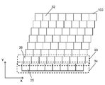
- FIG. 7 shows the pixel unit 32 scanned by the scanning unit 6.
- the heating cooker according to the third embodiment includes the microwave generation unit 2, the heating chamber 4, the infrared sensor 5, the scanning unit 6, the control unit 7, and the inverter 8 as in the first embodiment. Have.
- the same components as those in the first embodiment are denoted by the same reference numerals, and detailed description will be omitted.
- the heating cooker according to the third embodiment has a row 33, which is a first row in which a plurality of pixel units 32 are arranged, and a row 34, which is a second row.
- the position of the pixel 35 at one end of the row 33 and the position of the pixel 36 at one end of the row 34 in the X-axis direction are different.
- the pixel section 32 is disposed such that the infrared detection element 100 has a step-like shape.
- the pixel 35 and the pixel 36 are arranged to be shifted by c / 4.
- the infrared sensor 5 is scanned in the Y-axis direction of the pixel units 32 arranged stepwise. As shown in FIG. 7, the pixel 35 and the second pixel 36 are arranged to be shifted in the X-axis direction. As compared with the first embodiment, resolution in the X-axis direction can be improved when a plurality of temperature distributions are added to obtain a high-resolution temperature distribution as the pixels 35 and 36 are shifted. In the third embodiment, since the infrared detection element 100 is disposed so that the pixels 35 and 36 are offset by c / 4 in the X-axis direction, the resolution in the X-axis direction can be quadrupled. Thereby, the accuracy of the heating control of the heating cooker can be improved.
- the infrared sensor 5 is scanned so that the object to be heated 3 fits in the region where the temperature distribution is added.
- the distance for scanning the infrared sensor 5 becomes short. For this reason, a high resolution temperature distribution can be acquired in a short time, and the followability to the temperature change of the article 3 to be heated is improved.
- the heating cooker of the present disclosure includes: a microwave generation unit 2 that generates microwaves; a heating chamber 4 for storing the object to be heated 3; and an infrared sensor 5 installed inside the heating chamber 4; It has the scanning part 6 which scans the infrared sensor 5, and the control part 7 which controls the microwave generation part 2 based on the output of the infrared sensor 5.
- the infrared sensor 5 acquires a plurality of temperature distributions by acquiring the temperature distribution each time the predetermined distance is scanned.
- the control unit 7 controls the microwave generation unit 2 according to the temperature distribution obtained by adding the plurality of temperature distributions.
- the heating cooker of the present disclosure can reduce uneven heating and heat the object to be heated more evenly.
- the heating cooker of the present disclosure can heat the object to be heated more evenly regardless of the size of the temperature sensor object to be heated. Therefore, it is useful to heating cookers, such as a general household and business-use microwave ovens.
Landscapes
- Engineering & Computer Science (AREA)
- Chemical & Material Sciences (AREA)
- Combustion & Propulsion (AREA)
- Mechanical Engineering (AREA)
- General Engineering & Computer Science (AREA)
- Electric Ovens (AREA)
- Control Of High-Frequency Heating Circuits (AREA)
Abstract
L'invention concerne un dispositif de cuisson comprenant : une unité de production de micro-ondes qui produit des micro-ondes ; une chambre de chauffage destinée à contenir un objet à chauffer ; un capteur infrarouge qui est installé à l'intérieur de la chambre de chauffage ; une unité de balayage qui effectue un balayage avec le capteur infrarouge ; et une unité de commande qui commande l'unité de production de micro-ondes sur la base du signal de sortie du capteur infrarouge. Le capteur infrarouge obtient une pluralité de distributions de température par l'obtention d'une distribution de température chaque fois que le capteur infrarouge est amené à balayer une distance prédéfinie. L'unité de commande commande l'unité de production de micro-ondes en fonction d'une distribution de température obtenue par addition de la pluralité de distributions de température.
Priority Applications (2)
| Application Number | Priority Date | Filing Date | Title |
|---|---|---|---|
| CN201680016737.XA CN107429921B (zh) | 2015-04-24 | 2016-03-28 | 加热烹调器 |
| JP2017513954A JP6717296B2 (ja) | 2015-04-24 | 2016-03-28 | 加熱調理器 |
Applications Claiming Priority (2)
| Application Number | Priority Date | Filing Date | Title |
|---|---|---|---|
| JP2015088901 | 2015-04-24 | ||
| JP2015-088901 | 2015-04-24 |
Publications (1)
| Publication Number | Publication Date |
|---|---|
| WO2016170734A1 true WO2016170734A1 (fr) | 2016-10-27 |
Family
ID=57143823
Family Applications (1)
| Application Number | Title | Priority Date | Filing Date |
|---|---|---|---|
| PCT/JP2016/001775 Ceased WO2016170734A1 (fr) | 2015-04-24 | 2016-03-28 | Dispositif de cuisson |
Country Status (3)
| Country | Link |
|---|---|
| JP (1) | JP6717296B2 (fr) |
| CN (1) | CN107429921B (fr) |
| WO (1) | WO2016170734A1 (fr) |
Cited By (1)
| Publication number | Priority date | Publication date | Assignee | Title |
|---|---|---|---|---|
| DE102022210321A1 (de) | 2022-09-29 | 2024-04-04 | BSH Hausgeräte GmbH | Identifizieren von Gargut in einem Wärmebild |
Families Citing this family (2)
| Publication number | Priority date | Publication date | Assignee | Title |
|---|---|---|---|---|
| CN109357616B (zh) * | 2018-12-04 | 2020-08-28 | 温岭市第二绝缘材料厂 | 自动化变频光波炉 |
| CN110933795B (zh) * | 2019-11-15 | 2022-02-25 | 广东美的厨房电器制造有限公司 | 微波炉及其控制方法、装置以及存储介质 |
Citations (5)
| Publication number | Priority date | Publication date | Assignee | Title |
|---|---|---|---|---|
| JPH09159531A (ja) * | 1995-10-06 | 1997-06-20 | Matsushita Electric Ind Co Ltd | 温度検出装置 |
| JP2001065870A (ja) * | 1999-08-25 | 2001-03-16 | Toshiba Corp | 加熱調理器 |
| JP2002168457A (ja) * | 2000-04-28 | 2002-06-14 | Sanyo Electric Co Ltd | 電子レンジ |
| JP2009150699A (ja) * | 2007-12-19 | 2009-07-09 | Seiko Npc Corp | 測定対象物の位置測定システム |
| WO2014185033A1 (fr) * | 2013-05-17 | 2014-11-20 | パナソニック インテレクチュアル プロパティ コーポレーション オブ アメリカ | Capteur d'image thermique et interface d'utilisateur |
Family Cites Families (2)
| Publication number | Priority date | Publication date | Assignee | Title |
|---|---|---|---|---|
| JP2001304572A (ja) * | 2000-04-26 | 2001-10-31 | Sanyo Electric Co Ltd | 調理器 |
| JP2002013743A (ja) * | 2000-04-28 | 2002-01-18 | Sanyo Electric Co Ltd | 電子レンジ |
-
2016
- 2016-03-28 WO PCT/JP2016/001775 patent/WO2016170734A1/fr not_active Ceased
- 2016-03-28 CN CN201680016737.XA patent/CN107429921B/zh active Active
- 2016-03-28 JP JP2017513954A patent/JP6717296B2/ja active Active
Patent Citations (5)
| Publication number | Priority date | Publication date | Assignee | Title |
|---|---|---|---|---|
| JPH09159531A (ja) * | 1995-10-06 | 1997-06-20 | Matsushita Electric Ind Co Ltd | 温度検出装置 |
| JP2001065870A (ja) * | 1999-08-25 | 2001-03-16 | Toshiba Corp | 加熱調理器 |
| JP2002168457A (ja) * | 2000-04-28 | 2002-06-14 | Sanyo Electric Co Ltd | 電子レンジ |
| JP2009150699A (ja) * | 2007-12-19 | 2009-07-09 | Seiko Npc Corp | 測定対象物の位置測定システム |
| WO2014185033A1 (fr) * | 2013-05-17 | 2014-11-20 | パナソニック インテレクチュアル プロパティ コーポレーション オブ アメリカ | Capteur d'image thermique et interface d'utilisateur |
Cited By (2)
| Publication number | Priority date | Publication date | Assignee | Title |
|---|---|---|---|---|
| DE102022210321A1 (de) | 2022-09-29 | 2024-04-04 | BSH Hausgeräte GmbH | Identifizieren von Gargut in einem Wärmebild |
| WO2024068414A1 (fr) | 2022-09-29 | 2024-04-04 | BSH Hausgeräte GmbH | Identification d'aliments à cuire dans une image thermique |
Also Published As
| Publication number | Publication date |
|---|---|
| CN107429921A (zh) | 2017-12-01 |
| CN107429921B (zh) | 2019-06-28 |
| JP6717296B2 (ja) | 2020-07-01 |
| JPWO2016170734A1 (ja) | 2018-02-22 |
Similar Documents
| Publication | Publication Date | Title |
|---|---|---|
| CN112789947B (zh) | 用于处理烹饪物的方法和家用烹饪装置 | |
| CN105165118B (zh) | 通过微波炉优先将电磁能量对准物体的偏冷区域进行加热 | |
| US20140242227A1 (en) | Cooking device and method of controlling the same | |
| JP6717296B2 (ja) | 加熱調理器 | |
| US11506540B2 (en) | Calibration of a thermal imaging device for a surface cooking appliance | |
| CN106413163B (zh) | 半导体微波加热设备及其控制方法和控制装置 | |
| CN113348728B (zh) | 家用烹饪器具和用于运行家用烹饪器具的方法 | |
| EP3870009B1 (fr) | Appareil de cuisson chauffant comprenant un dispositif de mesure tridimensionnel | |
| CN105351981B (zh) | 一种加热方法和加热装置 | |
| US11617240B2 (en) | Microwave heating device and method for operating a microwave heating device | |
| JP6176919B2 (ja) | 加熱調理器 | |
| US20220086967A1 (en) | Microwave appliance and method for operating a microwave | |
| JP2010511274A (ja) | 温度に相関する信号を発生させ、処理して分析するための方法、およびそれに対応する装置 | |
| KR102015678B1 (ko) | 실리콘 로드 온도의 모니터링 및 제어를 위한 방법 및 시스템 | |
| US20200182610A1 (en) | Heating cooker including three dimensional measuring device | |
| US12390046B2 (en) | Systems and methods for achieving a user-specified temperature profile in a cooking appliance through heating control algorithms | |
| JP2005347000A (ja) | 誘導加熱調理器 | |
| JP2014534424A (ja) | 基板の温度を測定する装置 | |
| JP6007053B2 (ja) | 加熱調理器 | |
| JP4804560B2 (ja) | 誘導加熱調理器 | |
| US12550234B2 (en) | Calibration method for infrared sensor on microwave appliance sous vide system | |
| JP4735276B2 (ja) | 高周波加熱装置 | |
| JP6576823B2 (ja) | 固体撮像素子のクリーニング方法および放射線検出装置 | |
| JP2007080553A (ja) | 誘導加熱調理器 | |
| CN119968925A (zh) | 在热图像中辨识烹饪物 |
Legal Events
| Date | Code | Title | Description |
|---|---|---|---|
| 121 | Ep: the epo has been informed by wipo that ep was designated in this application |
Ref document number: 16782762 Country of ref document: EP Kind code of ref document: A1 |
|
| ENP | Entry into the national phase |
Ref document number: 2017513954 Country of ref document: JP Kind code of ref document: A |
|
| NENP | Non-entry into the national phase |
Ref country code: DE |
|
| 122 | Ep: pct application non-entry in european phase |
Ref document number: 16782762 Country of ref document: EP Kind code of ref document: A1 |