WO2016170896A1 - Dispositif médical - Google Patents
Dispositif médical Download PDFInfo
- Publication number
- WO2016170896A1 WO2016170896A1 PCT/JP2016/059153 JP2016059153W WO2016170896A1 WO 2016170896 A1 WO2016170896 A1 WO 2016170896A1 JP 2016059153 W JP2016059153 W JP 2016059153W WO 2016170896 A1 WO2016170896 A1 WO 2016170896A1
- Authority
- WO
- WIPO (PCT)
- Prior art keywords
- unit
- light
- incision
- treatment device
- emitting surface
- Prior art date
- Legal status (The legal status is an assumption and is not a legal conclusion. Google has not performed a legal analysis and makes no representation as to the accuracy of the status listed.)
- Ceased
Links
Images






Classifications
-
- A—HUMAN NECESSITIES
- A61—MEDICAL OR VETERINARY SCIENCE; HYGIENE
- A61B—DIAGNOSIS; SURGERY; IDENTIFICATION
- A61B18/00—Surgical instruments, devices or methods for transferring non-mechanical forms of energy to or from the body
- A61B18/04—Surgical instruments, devices or methods for transferring non-mechanical forms of energy to or from the body by heating
- A61B18/12—Surgical instruments, devices or methods for transferring non-mechanical forms of energy to or from the body by heating by passing a current through the tissue to be heated, e.g. high-frequency current
- A61B18/14—Probes or electrodes therefor
- A61B18/1442—Probes having pivoting end effectors, e.g. forceps
- A61B18/1445—Probes having pivoting end effectors, e.g. forceps at the distal end of a shaft, e.g. forceps or scissors at the end of a rigid rod
-
- A—HUMAN NECESSITIES
- A61—MEDICAL OR VETERINARY SCIENCE; HYGIENE
- A61B—DIAGNOSIS; SURGERY; IDENTIFICATION
- A61B17/00—Surgical instruments, devices or methods
- A61B17/00234—Surgical instruments, devices or methods for minimally invasive surgery
-
- A—HUMAN NECESSITIES
- A61—MEDICAL OR VETERINARY SCIENCE; HYGIENE
- A61B—DIAGNOSIS; SURGERY; IDENTIFICATION
- A61B18/00—Surgical instruments, devices or methods for transferring non-mechanical forms of energy to or from the body
- A61B18/18—Surgical instruments, devices or methods for transferring non-mechanical forms of energy to or from the body by applying electromagnetic radiation, e.g. microwaves
- A61B18/20—Surgical instruments, devices or methods for transferring non-mechanical forms of energy to or from the body by applying electromagnetic radiation, e.g. microwaves using laser
- A61B18/22—Surgical instruments, devices or methods for transferring non-mechanical forms of energy to or from the body by applying electromagnetic radiation, e.g. microwaves using laser the beam being directed along or through a flexible conduit, e.g. an optical fibre; Couplings or hand-pieces therefor
-
- A—HUMAN NECESSITIES
- A61—MEDICAL OR VETERINARY SCIENCE; HYGIENE
- A61B—DIAGNOSIS; SURGERY; IDENTIFICATION
- A61B5/00—Measuring for diagnostic purposes; Identification of persons
- A61B5/0059—Measuring for diagnostic purposes; Identification of persons using light, e.g. diagnosis by transillumination, diascopy, fluorescence
- A61B5/0082—Measuring for diagnostic purposes; Identification of persons using light, e.g. diagnosis by transillumination, diascopy, fluorescence adapted for particular medical purposes
- A61B5/0084—Measuring for diagnostic purposes; Identification of persons using light, e.g. diagnosis by transillumination, diascopy, fluorescence adapted for particular medical purposes for introduction into the body, e.g. by catheters
-
- A—HUMAN NECESSITIES
- A61—MEDICAL OR VETERINARY SCIENCE; HYGIENE
- A61B—DIAGNOSIS; SURGERY; IDENTIFICATION
- A61B5/00—Measuring for diagnostic purposes; Identification of persons
- A61B5/48—Other medical applications
- A61B5/4887—Locating particular structures in or on the body
- A61B5/489—Blood vessels
-
- A—HUMAN NECESSITIES
- A61—MEDICAL OR VETERINARY SCIENCE; HYGIENE
- A61B—DIAGNOSIS; SURGERY; IDENTIFICATION
- A61B90/00—Instruments, implements or accessories specially adapted for surgery or diagnosis and not covered by any of the groups A61B1/00 - A61B50/00, e.g. for luxation treatment or for protecting wound edges
- A61B90/30—Devices for illuminating a surgical field, the devices having an interrelation with other surgical devices or with a surgical procedure
-
- G—PHYSICS
- G01—MEASURING; TESTING
- G01N—INVESTIGATING OR ANALYSING MATERIALS BY DETERMINING THEIR CHEMICAL OR PHYSICAL PROPERTIES
- G01N21/00—Investigating or analysing materials by the use of optical means, i.e. using sub-millimetre waves, infrared, visible or ultraviolet light
- G01N21/84—Systems specially adapted for particular applications
- G01N21/88—Investigating the presence of flaws or contamination
- G01N21/90—Investigating the presence of flaws or contamination in a container or its contents
- G01N21/9009—Non-optical constructional details affecting optical inspection, e.g. cleaning mechanisms for optical parts, vibration reduction
-
- A—HUMAN NECESSITIES
- A61—MEDICAL OR VETERINARY SCIENCE; HYGIENE
- A61B—DIAGNOSIS; SURGERY; IDENTIFICATION
- A61B1/00—Instruments for performing medical examinations of the interior of cavities or tubes of the body by visual or photographical inspection, e.g. endoscopes; Illuminating arrangements therefor
- A61B1/12—Instruments for performing medical examinations of the interior of cavities or tubes of the body by visual or photographical inspection, e.g. endoscopes; Illuminating arrangements therefor with cooling or rinsing arrangements
- A61B1/126—Instruments for performing medical examinations of the interior of cavities or tubes of the body by visual or photographical inspection, e.g. endoscopes; Illuminating arrangements therefor with cooling or rinsing arrangements provided with means for cleaning in-use
-
- A—HUMAN NECESSITIES
- A61—MEDICAL OR VETERINARY SCIENCE; HYGIENE
- A61B—DIAGNOSIS; SURGERY; IDENTIFICATION
- A61B1/00—Instruments for performing medical examinations of the interior of cavities or tubes of the body by visual or photographical inspection, e.g. endoscopes; Illuminating arrangements therefor
- A61B1/12—Instruments for performing medical examinations of the interior of cavities or tubes of the body by visual or photographical inspection, e.g. endoscopes; Illuminating arrangements therefor with cooling or rinsing arrangements
- A61B1/127—Instruments for performing medical examinations of the interior of cavities or tubes of the body by visual or photographical inspection, e.g. endoscopes; Illuminating arrangements therefor with cooling or rinsing arrangements with means for preventing fogging
-
- A—HUMAN NECESSITIES
- A61—MEDICAL OR VETERINARY SCIENCE; HYGIENE
- A61B—DIAGNOSIS; SURGERY; IDENTIFICATION
- A61B17/00—Surgical instruments, devices or methods
- A61B17/00234—Surgical instruments, devices or methods for minimally invasive surgery
- A61B2017/00292—Surgical instruments, devices or methods for minimally invasive surgery mounted on or guided by flexible, e.g. catheter-like, means
- A61B2017/00296—Surgical instruments, devices or methods for minimally invasive surgery mounted on or guided by flexible, e.g. catheter-like, means mounted on an endoscope
-
- A—HUMAN NECESSITIES
- A61—MEDICAL OR VETERINARY SCIENCE; HYGIENE
- A61B—DIAGNOSIS; SURGERY; IDENTIFICATION
- A61B18/00—Surgical instruments, devices or methods for transferring non-mechanical forms of energy to or from the body
- A61B2018/00571—Surgical instruments, devices or methods for transferring non-mechanical forms of energy to or from the body for achieving a particular surgical effect
- A61B2018/00601—Cutting
-
- A—HUMAN NECESSITIES
- A61—MEDICAL OR VETERINARY SCIENCE; HYGIENE
- A61B—DIAGNOSIS; SURGERY; IDENTIFICATION
- A61B18/00—Surgical instruments, devices or methods for transferring non-mechanical forms of energy to or from the body
- A61B2018/00571—Surgical instruments, devices or methods for transferring non-mechanical forms of energy to or from the body for achieving a particular surgical effect
- A61B2018/0063—Sealing
-
- A—HUMAN NECESSITIES
- A61—MEDICAL OR VETERINARY SCIENCE; HYGIENE
- A61B—DIAGNOSIS; SURGERY; IDENTIFICATION
- A61B18/00—Surgical instruments, devices or methods for transferring non-mechanical forms of energy to or from the body
- A61B2018/00636—Sensing and controlling the application of energy
- A61B2018/00642—Sensing and controlling the application of energy with feedback, i.e. closed loop control
-
- A—HUMAN NECESSITIES
- A61—MEDICAL OR VETERINARY SCIENCE; HYGIENE
- A61B—DIAGNOSIS; SURGERY; IDENTIFICATION
- A61B18/00—Surgical instruments, devices or methods for transferring non-mechanical forms of energy to or from the body
- A61B2018/00636—Sensing and controlling the application of energy
- A61B2018/0066—Sensing and controlling the application of energy without feedback, i.e. open loop control
-
- A—HUMAN NECESSITIES
- A61—MEDICAL OR VETERINARY SCIENCE; HYGIENE
- A61B—DIAGNOSIS; SURGERY; IDENTIFICATION
- A61B18/00—Surgical instruments, devices or methods for transferring non-mechanical forms of energy to or from the body
- A61B2018/00636—Sensing and controlling the application of energy
- A61B2018/00696—Controlled or regulated parameters
- A61B2018/00702—Power or energy
- A61B2018/00708—Power or energy switching the power on or off
-
- A—HUMAN NECESSITIES
- A61—MEDICAL OR VETERINARY SCIENCE; HYGIENE
- A61B—DIAGNOSIS; SURGERY; IDENTIFICATION
- A61B18/00—Surgical instruments, devices or methods for transferring non-mechanical forms of energy to or from the body
- A61B2018/00636—Sensing and controlling the application of energy
- A61B2018/00904—Automatic detection of target tissue
-
- A—HUMAN NECESSITIES
- A61—MEDICAL OR VETERINARY SCIENCE; HYGIENE
- A61B—DIAGNOSIS; SURGERY; IDENTIFICATION
- A61B18/00—Surgical instruments, devices or methods for transferring non-mechanical forms of energy to or from the body
- A61B2018/00982—Surgical instruments, devices or methods for transferring non-mechanical forms of energy to or from the body combined with or comprising means for visual or photographic inspections inside the body, e.g. endoscopes
-
- A—HUMAN NECESSITIES
- A61—MEDICAL OR VETERINARY SCIENCE; HYGIENE
- A61B—DIAGNOSIS; SURGERY; IDENTIFICATION
- A61B90/00—Instruments, implements or accessories specially adapted for surgery or diagnosis and not covered by any of the groups A61B1/00 - A61B50/00, e.g. for luxation treatment or for protecting wound edges
- A61B90/30—Devices for illuminating a surgical field, the devices having an interrelation with other surgical devices or with a surgical procedure
- A61B2090/306—Devices for illuminating a surgical field, the devices having an interrelation with other surgical devices or with a surgical procedure using optical fibres
-
- A—HUMAN NECESSITIES
- A61—MEDICAL OR VETERINARY SCIENCE; HYGIENE
- A61B—DIAGNOSIS; SURGERY; IDENTIFICATION
- A61B2218/00—Details of surgical instruments, devices or methods for transferring non-mechanical forms of energy to or from the body
- A61B2218/001—Details of surgical instruments, devices or methods for transferring non-mechanical forms of energy to or from the body having means for irrigation and/or aspiration of substances to and/or from the surgical site
- A61B2218/002—Irrigation
- A61B2218/005—Irrigation using gas or vapor, e.g. for protection or purging
-
- A—HUMAN NECESSITIES
- A61—MEDICAL OR VETERINARY SCIENCE; HYGIENE
- A61B—DIAGNOSIS; SURGERY; IDENTIFICATION
- A61B2218/00—Details of surgical instruments, devices or methods for transferring non-mechanical forms of energy to or from the body
- A61B2218/001—Details of surgical instruments, devices or methods for transferring non-mechanical forms of energy to or from the body having means for irrigation and/or aspiration of substances to and/or from the surgical site
- A61B2218/002—Irrigation
- A61B2218/006—Irrigation for smoke evacuation
-
- A—HUMAN NECESSITIES
- A61—MEDICAL OR VETERINARY SCIENCE; HYGIENE
- A61B—DIAGNOSIS; SURGERY; IDENTIFICATION
- A61B2218/00—Details of surgical instruments, devices or methods for transferring non-mechanical forms of energy to or from the body
- A61B2218/001—Details of surgical instruments, devices or methods for transferring non-mechanical forms of energy to or from the body having means for irrigation and/or aspiration of substances to and/or from the surgical site
- A61B2218/007—Aspiration
-
- A—HUMAN NECESSITIES
- A61—MEDICAL OR VETERINARY SCIENCE; HYGIENE
- A61B—DIAGNOSIS; SURGERY; IDENTIFICATION
- A61B2218/00—Details of surgical instruments, devices or methods for transferring non-mechanical forms of energy to or from the body
- A61B2218/001—Details of surgical instruments, devices or methods for transferring non-mechanical forms of energy to or from the body having means for irrigation and/or aspiration of substances to and/or from the surgical site
- A61B2218/007—Aspiration
- A61B2218/008—Aspiration for smoke evacuation
-
- A—HUMAN NECESSITIES
- A61—MEDICAL OR VETERINARY SCIENCE; HYGIENE
- A61B—DIAGNOSIS; SURGERY; IDENTIFICATION
- A61B2505/00—Evaluating, monitoring or diagnosing in the context of a particular type of medical care
- A61B2505/05—Surgical care
-
- A—HUMAN NECESSITIES
- A61—MEDICAL OR VETERINARY SCIENCE; HYGIENE
- A61B—DIAGNOSIS; SURGERY; IDENTIFICATION
- A61B2562/00—Details of sensors; Constructional details of sensor housings or probes; Accessories for sensors
- A61B2562/02—Details of sensors specially adapted for in-vivo measurements
- A61B2562/0233—Special features of optical sensors or probes classified in A61B5/00
- A61B2562/0238—Optical sensor arrangements for performing transmission measurements on body tissue
-
- A—HUMAN NECESSITIES
- A61—MEDICAL OR VETERINARY SCIENCE; HYGIENE
- A61B—DIAGNOSIS; SURGERY; IDENTIFICATION
- A61B2562/00—Details of sensors; Constructional details of sensor housings or probes; Accessories for sensors
- A61B2562/18—Shielding or protection of sensors from environmental influences, e.g. protection from mechanical damage
-
- A—HUMAN NECESSITIES
- A61—MEDICAL OR VETERINARY SCIENCE; HYGIENE
- A61B—DIAGNOSIS; SURGERY; IDENTIFICATION
- A61B90/00—Instruments, implements or accessories specially adapted for surgery or diagnosis and not covered by any of the groups A61B1/00 - A61B50/00, e.g. for luxation treatment or for protecting wound edges
- A61B90/70—Cleaning devices specially adapted for surgical instruments
-
- A—HUMAN NECESSITIES
- A61—MEDICAL OR VETERINARY SCIENCE; HYGIENE
- A61F—FILTERS IMPLANTABLE INTO BLOOD VESSELS; PROSTHESES; DEVICES PROVIDING PATENCY TO, OR PREVENTING COLLAPSING OF, TUBULAR STRUCTURES OF THE BODY, e.g. STENTS; ORTHOPAEDIC, NURSING OR CONTRACEPTIVE DEVICES; FOMENTATION; TREATMENT OR PROTECTION OF EYES OR EARS; BANDAGES, DRESSINGS OR ABSORBENT PADS; FIRST-AID KITS
- A61F9/00—Methods or devices for treatment of the eyes; Devices for putting in contact-lenses; Devices to correct squinting; Apparatus to guide the blind; Protective devices for the eyes, carried on the body or in the hand
- A61F9/007—Methods or devices for eye surgery
- A61F9/008—Methods or devices for eye surgery using laser
- A61F9/00821—Methods or devices for eye surgery using laser for coagulation
Definitions
- the present invention relates to a medical device that prevents dirt generated by an incision operation of a treatment device from inhibiting light emitted from a light emitting surface to a subject.
- WO2013 / 134411 discloses a device equipped with a function of sensing a blood vessel with light such as a laser. Specifically, including a laser Doppler velocimeter, generating an alarm signal when a blood vessel with a diameter larger than a threshold is detected, generating an alarm display, LED at the tip of the device is lit / flash emission / color change It describes what can be done and stops the energy applicator according to the sensing value (off control in on / off control).
- the endoscope is removed from the body cavity or the lumen, and the tip of the endoscope is washed with hot water or wiped with gauze or the like. Since it is necessary to insert the endoscope apparatus again, the operation becomes complicated.
- the present invention has been made in view of the above circumstances, and an object of the present invention is to provide a medical device that prevents dirt generated by an incision operation of a treatment device from adhering to a light emitting surface for emitting light to a subject. It is said.
- a medical device includes a treatment device that can be opened by applying energy in a subject, and a light emitting surface that is connected to the treatment device and emits light to the subject.
- a treatment device that can be opened by applying energy in a subject
- a light emitting surface that is connected to the treatment device and emits light to the subject.
- FIG. 6 is a flowchart showing the operation of the medical device according to the first embodiment.
- tip part of a cutting device when cutting operation is not performed.
- movement In the said Embodiment 1, the enlarged view which shows the mode of the dirt adhesion prevention part when the incision device is performing incision operation
- steering-wheel part vicinity of an incision device In the said Embodiment 1, the figure which shows the other example of arrangement
- movement The side view which shows the structure of the incision device in the modification of the said Embodiment 3.
- FIG. Sectional drawing which shows the structure of the front-end
- FIG. Sectional drawing which shows the structure of the front-end
- Embodiment 4 of this invention the figure which shows the mode of the stain
- the said Embodiment 4 the figure which shows the mode of the stain
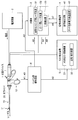
- FIG. 1 is a diagram showing a configuration example of a medical device.
- the medical device of the present embodiment includes, for example, an incision device 1, a power supply device 2, an optical housing 3, a signal processing device 4, a mist reduction device 5, and a handle unit operation circuit 6.
- the incision device 1 is an insert that is inserted into a body cavity of a subject, and is a treatment device (energy device) that can incise the subject's tissue by applying energy such as heat, light, or current to the subject.
- a treatment function for sealing the subject is provided if necessary.
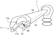
- the incision device 1 includes an insertion portion 10 to be inserted into a subject, a treatment portion 11 provided at a distal end portion of the insertion portion 10, and a handle portion 12 for operating the incision device 1.
- the optical fiber 30 is inserted from the proximal end side toward the distal end portion on the treatment section 11 side.
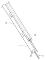
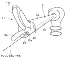
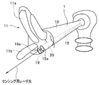
- FIG. 2 is a perspective view showing the configuration of the distal end portion of the incision device 1.
- a treatment unit 11 including an upper jaw 11a and a lower jaw 11b (see FIG. 4 and the like) for sandwiching and treating a subject is provided.
- the light emitting surface 30 a (see FIG. 5 etc.) at the tip is exposed (that is, light (for example, laser light) can be irradiated toward the subject) at the irradiation part.
- An optical fiber 30 is disposed.
- the power supply device 2 supplies treatment energy as, for example, a current to the incision device 1.
- the optical housing 3 is connected to the proximal end side of the optical fiber 30 described above, and supplies laser light to the optical fiber 30.
- the optical housing 3 includes a blood vessel sensing laser light source 31, a guide laser light source 32, and a photodetector 33.
- the blood vessel sensing laser light source 31 is configured as a semiconductor light source device, and is a light source unit that generates laser light for irradiating a subject from a light emitting surface 30a and supplies the laser light to an optical fiber 30 that is an irradiation unit. .
- the laser light generated by the blood vessel sensing laser light source 31 is transmitted through the optical fiber 30 and is irradiated onto the subject from the light exit surface 30a to detect illumination light (sensing for detection). Laser light).
- the guide laser light source 32 is a notifying unit that irradiates and detects light to a detected blood vessel when a blood vessel is detected by a blood vessel detection circuit 41 described later. Specifically, the guide laser light source 32 generates guide laser light (referred to as guide light as appropriate) as notification light for guiding the detected blood vessel. This guide light is also irradiated to the subject via the optical fiber 30. The image of the subject irradiated with the guide light is acquired by being imaged by an endoscope such as a laparoscope (Laparo) inserted into the body cavity of the subject together with the incision device 1, and an endoscopic image and various types of information. It is observed through a monitor or the like that displays.
- an endoscope such as a laparoscope (Laparo) inserted into the body cavity of the subject together with the incision device 1, and an endoscopic image and various types of information. It is observed through a monitor or the like that displays.
- the photodetector 33 is a detection unit that detects return light (reflected light) from the body cavity of the subject of the sensing laser light irradiated by the blood vessel sensing laser light source 31 that is a light source unit.
- the signal processing device 4 analyzes the sensing laser light emitted from the optical housing 3 and the return light from the subject, determines the presence or absence of the blood vessel of the subject, and further determines that there is a blood vessel.
- the optical housing 3 is controlled to emit guide light.
- the signal processing device 4 includes a blood vessel detection circuit 41 and a guide light oscillation signal transmission unit 42.
- the blood vessel detection circuit 41 is based on the scattered information (specifically, the Doppler frequency spectrum (hereinafter referred to as the blood flow velocity) of blood cells (specifically, red blood cells including hemoglobin) in the blood vessel). It is simply a blood vessel detection unit that determines the presence or absence of blood vessels based on the frequency spectrum))).
- the scattered information specifically, the Doppler frequency spectrum (hereinafter referred to as the blood flow velocity) of blood cells (specifically, red blood cells including hemoglobin) in the blood vessel). It is simply a blood vessel detection unit that determines the presence or absence of blood vessels based on the frequency spectrum)).
- the guide light oscillation signal transmission unit 42 transmits a trigger signal for oscillating guide light to the guide laser light source 32 of the optical housing 3 when the blood vessel detection circuit 41 determines that a blood vessel exists.
- the mist reducing device 5 is for reducing the adhesion of substances such as smoke and mist generated from the subject or body fluid (for example, blood) to the light emitting surface 30a of the laser.
- a substance such as smoke, mist, or body fluid (for example, blood) is subjected to treatment such as incision by applying energy to the subject with the incision device 1, for example, a subject to which energy is applied (for example, Adipose tissue).
- the mist reducing device 5 is illustrated as if it is a separate body from the incision device 1, but it may be integrated with the incision device 1, and a part of the mist reducing device 5 is incised.
- the device 1 and the other part may be separate from the lancing device 1, and are not restricted by the arrangement.
- the mist reducing device 5 is linked to the cutting operation of the cutting device 1 (for example, linked to the energy output or linked to the opening / closing operation of the upper jaw 11a and the lower jaw 11b of the treatment section 11).
- 30 is a dirt adhesion preventing unit that prevents dirt from adhering to the light emitting surface 30a of the 30, and includes, for example, at least one of a mechanical mist removing mechanism 51 and an air supply / suction device 52.
- the mechanical mist removal mechanism 51 is configured so that a substance generated from the subject by the incision operation of the incision device 1 (representing this substance, hereinafter simply referred to as mist MST (see FIG. 12 and the like) as appropriate) on the light emitting surface 30a. It is a mechanical mechanism that mechanically prevents adhesion.
- the air / suction device 52 reduces the adhesion of the mist MST to the light emitting surface 30a by sucking and discharging the mist MST by the suction mechanism, or supplies air into the subject by the air supply mechanism. By doing so, the mist concentration in the subject is reduced to reduce the mist MST from adhering to the light emitting surface 30a.
- the handle portion operation circuit 6 receives an operation signal transmitted in response to an operation of an operation member provided in the handle portion 12 and transmits a signal corresponding to the operation content to the optical housing 3 or the mist reducing device 5. Is.
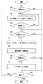
- FIG. 3 is a flowchart showing the operation of the medical device.
- the handle portion operation circuit 6 determines whether or not an operation for performing an incision by the incision device 1 has been performed on the handle portion 12 (step S1).
- an operation signal is transmitted to the handle portion operation circuit 6 as indicated by arrows A1 and A9. Based on the received operation signal, the presence / absence of the operation and the operation content are determined.
- an incision operation signal is displayed as indicated by an arrow A1.
- a signal for performing a mist reduction process is transmitted from the handle unit operation circuit 6 to the mist reducing device 5 as indicated by an arrow A2, and a signal for performing mist reduction processing is transmitted from the handle unit 12 to the handle unit operating circuit 6.
- Mitigation processing is performed.
- the blood vessel sensing laser light source 31 and the guide laser light source 32 of the optical housing 3 are locked in a power-off state (however, when the power is turned off, the laser light is stabilized again when the power is turned on thereafter. Since it takes time to do so, the supply of the laser light to the optical fiber 30 may be stopped. Then, a current is supplied from the power supply device 2 to the incision device 1, and an incision operation by the incision device 1 is executed (step S2).
- step S3 it is determined whether or not an operation for ending the incision operation by the incision device 1 has been performed from the handle portion 12 (step S3).
- step S2 if it is determined that the operation for ending the incision operation has not been performed, the process returns to step S2 and the above-described processing is performed.
- step S2 If it is determined in step S2 that an operation for ending the incision operation has been performed, or if it is determined in step S1 that an operation for incising is not performed, a blood vessel is detected from the handle portion 12.
- An operation for performing blood vessel sensing to be notified for example, an operation of continuously pressing the dial portion 17a, the first push portion 17b, the second push portion 18, the first button portion 16 as shown in FIGS. 9 to 11, or It is determined whether or not a foot switch operation has been performed (step S4).
- an operation signal as indicated by an arrow A9 is transmitted from the handle unit 12 to the handle unit operation circuit 6.
- a signal is transmitted from the handle unit operation circuit 6 to the optical housing 3 as indicated by an arrow A3, and the blood vessel sensing in the optical housing 3 is performed.
- the power sources of the laser light source 31 and the guide laser light source 32 are turned on.
- a sensing laser beam is emitted from the blood vessel sensing laser light source 31, and the sensing laser beam is transmitted through the optical fiber 30 as indicated by an arrow A4, and is irradiated onto the subject from the light emitting surface 30a.
- the return light from the body cavity of the subject is transmitted through the optical fiber 30 as indicated by the arrow A5 and detected by the photodetector 33 (step S5).
- the detection signal of the photodetector 33 is transmitted to the signal processing device 4 as indicated by an arrow A6, and the presence or absence of a blood vessel is determined by the blood vessel detection circuit 41 (step S6).
- the processing branch is performed depending on whether the determination result by the blood vessel detection circuit 41 is a blood vessel (step S7).
- the trigger signal for causing the guide light oscillation signal transmitting unit 42 to oscillate the guide light (note that this trigger signal is determined to have no blood vessel). Is not transmitted to the guide laser light source 32 as indicated by an arrow A7, and the guide laser light source 32 emits guide light. The emitted guide light is transmitted through the optical fiber 30 as indicated by an arrow A8, and is irradiated onto the subject from the light exit surface 30a (step S8).
- step S7 If the determination result in step S7 is that there is no blood vessel, or if it is determined in step S4 that an operation for performing blood vessel sensing has not been performed, an operation for ending this process is performed. (Step S9), when the operation to end is not performed, the process returns to Step S1 and the above-described processing is repeated, and when the operation to end is performed, this processing ends.
- FIG. 4 is a diagram showing a state in which the optical fiber protrudes from the distal end portion of the incision device 1 when the incision operation is not performed
- FIG. 5 is an illustration of the optical fiber of the incision device 1 when the incision operation is not performed.
- 6 is an enlarged view showing a state of protruding from the distal end portion
- FIG. 6 is a view showing a state of the dirt adhesion preventing portion when the cutting device 1 is performing the cutting operation
- FIG. 7 is a drawing showing the cutting device 1 performing the cutting operation. It is an enlarged view which shows the mode of the dirt adhesion prevention part at the time.
- an optical fiber insertion channel 15 is formed from the proximal side to the distal end side, and an optical fiber 30 is inserted into the optical fiber insertion channel 15.
- the light emitting surface 30a at the tip of the optical fiber 30 protrudes from the tip opening 15a of the optical fiber insertion channel 15 and is exposed as shown in FIGS. Yes.
- the light emitting surface 30a at the tip of the optical fiber 30 is accommodated in the tip opening 15a of the optical fiber insertion channel 15 as shown in FIGS.
- the mechanical mist removing mechanism 51 which is a dirt adhesion preventing unit, retreats the light emitting surface 30a into the incision device 1 when the incision device 1 performs an incision operation. It includes an advance / retreat mechanism that returns the light exit surface 30a to a state of projecting from the incision device 1 when the incision operation is not performed.
- the advancing / retreating mechanism may be configured to be interlocked with the opening / closing operation of the upper jaw 11a and the lower jaw 11b that are opened / closed by opening / closing operations of the first handle 12a and the second handle 12b (see FIG. 8) of the handle portion 12.
- a configuration using an appropriate drive source such as a separate motor or solenoid plunger may be used, and the configuration is not limited to a specific configuration.
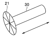
- the mechanical mist removal mechanism 51 which is a dirt adhesion prevention part in this embodiment includes the wiping part 21 provided in the tip opening 15a (however, the mechanical mist removal mechanism 51 includes the wiping part 21). However, this does not prevent the configuration including only the advance / retreat mechanism described above).
- the wiping portion 21 is configured as a rubber valve that can be opened and closed by making a plurality of cuts from the center toward the periphery, for example, on the inner surface of the rubber valve on the optical fiber insertion channel 15 side. A member for wiping off dirt such as gauze is attached.
- the wiping unit 21 substantially closes the tip opening 15a when the light emitting surface 30a is accommodated in the tip opening 15a to prevent the mist MST from adhering to the light emitting surface 30a and the light emitting surface 30a.
- the mist MST adhering to the tip opening 15a can be wiped off by gauze or the like on the inner surface. That is, the cleaning of the light emitting surface 30a with gauze or the like on the inner surface of the wiping unit 21 is performed every time the light emitting surface 30a protrudes from the tip opening 15a.
- the laser light source for blood vessel sensing 31 and the guide laser light source 32 are automatically turned off (or as described above, the supply of laser light may be stopped, and so on) (see step S2 in FIG. 3).
- the light emitting surface 30 a of the optical fiber 30 protrudes from the tip opening 15 a of the optical fiber insertion channel 15, sensing laser light is emitted.
- At least one of the signal processing device 4 and the optical housing 3 functioning as a control unit controls the light source unit so as to stop the supply of the laser light to the optical fiber 30.
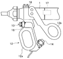
- FIG. 8 is a view showing an example of the arrangement of the operation members for preventing the adhesion of dirt in the vicinity of the handle portion 12 of the incision device 1.
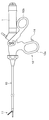
- the handle portion 12 is an operation portion that performs an operation of incising the tissue of the subject, and has a structure in which the first handle 12a and the second handle 12b each having a finger ring are opened and closed by a hinge mechanism.
- the third button portion 13 is on the insertion direction side of the proximal end portion (upper end portion) of the first handle 12a, and the second handle 12b side of the distal end portion (lower end portion) of the first handle 12a.
- Each has a second button portion 14.
- the third button part 13 and the second button part 14 are provided at positions where they can be operated (directly or indirectly) with the hand having the handle part 12.
- the third button part 13 performs an operation of pressing the operator using a finger (for example, an index finger) of the hand holding the handle part 12.
- the second button portion 14 is pushed on the surface of the second handle 12b by the operator holding the handle portion 12 with his / her hand and narrowing the distance between the first handle 12a and the second handle 12b (accordingly).
- the second button portion 14 is not directly pressed, but is indirectly operated by operating the first handle 12a and the second handle 12b).
- the light emission surface 30a of the optical fiber 30 is connected to the optical fiber insertion channel 15 in conjunction with any of the following operations (a) and (b). It is designed to move in.
- FIG. 9 is a diagram showing another example of the arrangement of the operation member related to prevention of dirt adhesion near the handle portion 12 of the incision device 1
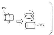
- FIG. 10 is an enlarged view of an example of the operation of the operation member related to prevention of dirt adhesion.
- FIG. 11 is an enlarged view showing another example of the operation of the operation member for preventing the adhesion of dirt.
- the first button portion 16 is supported on the side surface of the third button portion 13 of the first handle 12a, and the first handle 12a and the second handle 12b are supported.
- the first operating portion 17 may be provided on the side surface closer to the proximal side of the second handle 12b of the main body, and the second push portion 18 may be provided on the upper surface of the main body supporting the first handle 12a and the second handle 12b.
- the first operation unit 17 is configured as a rotary operation type dial unit 17a as shown in FIG. 10 or a press operation type first push unit 17b as shown in FIG.
- the 2nd pushing part 18 is comprised, for example as a pushing operation type pushing part.
- the first button portion 16, the first operation portion 17, and the second push portion 18 are also provided at positions where the hand having the handle portion 12 can be operated. Note that it is not necessary to provide all of the first button unit 16, the first operation unit 17, and the second pressing unit 18. For example, one or more buttons may be provided.
- the first button unit 16, the first operation unit 17, and the second push unit 18 are operated to irradiate sensing laser light and guide light from the optical housing 3.
- the irradiation of the sensing laser beam and the irradiation of the guide light is permitted only when the light emitting surface 30a of the optical fiber 30 protrudes from the tip opening 15a of the optical fiber insertion channel 15, and the light emission is performed. Any irradiation is prohibited when the surface 30a is housed in the optical fiber insertion channel 15.
- the light of the optical fiber 30 is further linked to the operation (c) below.
- the emission surface 30a may be moved into the optical fiber insertion channel 15 to further reduce mist.
- the mist reducing device 5 that is the dirt adhesion preventing unit prevents the dirt from adhering to the light emitting surface 30 a of the optical fiber 30 in conjunction with the incision operation of the incision device 1. For this reason, it is possible to suppress a decrease in the intensity of light emitted from the light emitting surface 30a to the subject.
- the mechanical mist removal mechanism 51 which is a dirt adhesion prevention unit, retracts the light emitting surface 30a into the incision device 1, and the incision device 1 does not perform the incision operation. Since the light emitting surface 30a is configured to include the advance / retreat mechanism that returns the light exit surface 30a to the state protruding from the incision device 1, the adhesion of dirt can be effectively reduced.
- the wiping portion 21 is further provided, when the optical fiber 30 is accommodated in the optical fiber insertion channel 15, the mist MST is prevented from adhering to the light emitting surface 30a, and the light emitting surface 30a is provided at the tip opening 15a. When protruding from the mist, the mist MST adhering to the tip opening 15a can be wiped off.
- the incision device 1 When the incision device 1 performs an incision operation, that is, when the light emitting surface 30a is accommodated in the optical fiber insertion channel 15, the supply of laser light from the optical housing 3 to the optical fiber 30 is stopped. Therefore, unnecessary laser light is not irradiated, and it is possible to prevent the laser light from being reflected in the incision device 1 to generate return light.
- the mist MST is not attached to the light emitting surface 30a. It is possible to maintain a high blood vessel detection sensitivity.
- FIG. 12 is a diagram showing the configuration of the dirt adhesion preventing portion.
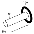
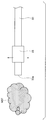
- the mechanical mist removal mechanism 51 of the present embodiment includes a vibration unit 22 that is provided at the tip of the optical fiber 30 and is configured by an ultrasonic vibration unit (actuator) or the like. As shown in FIG. 12, the vibration part 22 is bonded and fixed to the outer peripheral surface of the tip part of the optical fiber 30.
- actuator ultrasonic vibration unit
- the vibration unit 22 is driven in conjunction with the operation, as indicated by an arrow in FIG. Vibrate.
- the tip of the optical fiber 30 fixed to the vibration part 22 is also vibrated, and even if dirt due to the mist MST adheres to the light emitting surface 30a, the dirt is blown off and eliminated.
- FIG. 13 is a diagram showing an example of controlling the output of the blood vessel sensing laser light source 31 in accordance with the presence or absence of the incision operation of the incision device 1. Since the control of the guide laser light source 32 can be performed in substantially the same manner, the output control of the blood vessel sensing laser light source 31 will be described here.
- the vibration unit 22 is not driven, and when performing normal blood vessel sensing, the light intensity W is the minimum intensity WL, which is the intensity range of the sensing laser light when performing blood vessel sensing. It is set so that the intensity range WR1 is equal to or greater than the maximum intensity WH (WL ⁇ W ⁇ WH).
- the blood vessel sensing laser light source 31 is set so that the light intensity W of the sensing laser light is in the intensity range WR0 of 0 ⁇ W ⁇ WL while the vibration unit 22 is driven. Since the intensity range WR0 includes 0, that is, while the vibration unit 22 is being driven, the blood vessel sensing laser light source 31 may be turned off.
- the laser light supplied to the optical fiber 30 is used (sensing) output range (when sensing)
- the laser light supplied to the optical fiber 30 is output less than the output range during use (corresponds to the intensity range WR0). ) To be controlled.
- the mechanical mist removing mechanism 51 serving as the dirt adhesion preventing unit vibrates the light emitting surface 30a of the optical fiber 30 while having substantially the same effect as the first embodiment described above. Since the portion 22 is included, dirt can be removed by electrical control in conjunction with the input of the operation signal from the operation member.
- the laser beam supplied to the optical fiber 30 has an output value that is less than the output range during use while the vibrating unit 22 is vibrating, the consumption of the blood vessel sensing laser light source 31 and the guide laser light source 32 is reduced. Electric power can be effectively reduced.
- the output value while the vibration unit 22 is vibrating is not set to 0, it is possible to shorten the standby time until the laser light is returned to the output value in the in-use output range.
- FIGS. 14 to 18 show Embodiment 3 of the present invention
- FIG. 14 is a view showing a state of the dirt adhesion preventing portion when the incision device 1 is not performing the incision operation.
- the mechanical mist removal mechanism 51 of the present embodiment includes a shielding portion 23 provided at the distal end opening 15a of the optical fiber insertion channel 15.
- the shielding portion 23 is a mechanical mechanism that can change the tip opening 15a between an open state and a closed state, and is configured as a shutter mechanism that can be opened and closed, for example.
- the shielding part 23 is opened as shown in FIG.
- the shielding part 23 is closed as shown in FIG.
- the shielding unit 23 is closed in conjunction with the operation.
- the blood vessel sensing laser light source 31 and the guide laser light source 32 are automatically turned off in conjunction with the closing of the shielding portion 23 (see step S2 in FIG. 3). Laser light is emitted from the optical housing 3 in conjunction with the opening of the shield 23.
- FIGS. 16 is a side view showing the configuration of the incision device 1
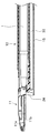
- FIG. 17 is a cross-sectional view showing the configuration of the tip when the incision device 1 is not performing the incision operation
- FIG. It is sectional drawing which shows the structure of the front-end
- the treatment section 11 provided at the distal end portion of the incision device 1 as shown in FIG. 16 is provided with the upper jaw 11a and the lower jaw 11b as shown in FIGS. 17 and 18 so as to be opened and closed as described above.
- the lower jaw 11b extends integrally (fixedly) from the insertion portion 10 of the incision device 1, but the upper jaw 11a is rotated by a hinge mechanism to open and close the lower jaw 11b. It is supposed to be.
- the operator holds the handle portion 12 by hand and narrows the distance between the first handle 12a and the second handle 12b, so that the upper jaw 11a rotates and closes in the direction approaching the lower jaw 11b. It has become.
- the shielding portion 24 of this modified example rotates in conjunction with the rotation of the upper jaw 11a (for example, integrally with the upper jaw 11a), thereby closing the tip opening 15a. It is a mechanical mechanism that makes a transition to the state. That is, with respect to the lower jaw 11b, when the upper jaw 11a is open, the shielding portion 24 also opens the tip opening 15a, and when the upper jaw 11a is closed, the shielding portion 24 also closes the tip opening 15a. To do.
- the same effects as those of the first and second embodiments described above are obtained, and when the cutting device 1 does not perform the cutting operation, the light emitting surface 30a is opened, and the cutting device 1 performs the cutting operation. Since the shielding portions 23 and 24 that can be opened and closed are provided to shield the light emitting surface 30a when performing the above, the shielding portions 23 and 24 are closed to prevent the mist MST from adhering to the light emitting surface 30a. .
- the cutting device 1 performs a cutting operation, that is, when the shielding portions 23 and 24 are closed, the supply of laser light from the optical housing 3 to the optical fiber 30 is stopped, which is unnecessary. Without irradiating the laser beam, it is possible to prevent the laser beam from being reflected in the incision device 1 to generate return light.
- FIG. 19 and 20 show the fourth embodiment of the present invention
- FIG. 19 is a diagram showing a state of the dirt adhesion preventing unit when the cutting device 1 is not performing the cutting operation.
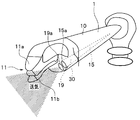
- a fluid channel 19 is formed from the proximal side to the distal side.
- the tip opening 19a of the fluid channel 19 (the opening of the fluid channel 19 at the tip of the cutting device 1) is preferably disposed close to the tip opening 15a of the optical fiber insertion channel 15.
- the fluid channel 19 can carry a fluid such as a gas or a liquid in either a sending direction or a sucking direction. Therefore, for example, when a gas is used as the fluid, the fluid channel 19 serves both as an air supply channel and a suction channel (a channel for performing intake). Alternatively, when water or the like is used as the fluid, the fluid channel 19 serves as both a water supply channel and a suction channel.
- the incision device 1 when the incision device 1 performs an incision operation, air is supplied from the fluid channel 19 to the space where the light emitting surface 30a emits light, and the light emitting surface 30a of the optical fiber 30 is supplied.
- the mist MST in the vicinity is excluded to prevent the mist MST from adhering to the light emitting surface 30a. Accordingly, the fluid channel 19 is included in the air / suction device 52 of the mist reducing device 5.
- FIG. 20 is a diagram illustrating a state of the dirt adhesion preventing unit when the incision device 1 is performing the incision operation.
- air supply from the fluid channel 19 may be further performed so as to form a so-called air curtain flow in the vicinity of the light emitting surface 30a.
- an air curtain flow is formed between the light emitting surface 30a and the upper jaw 11a and the lower jaw 11b that are the source of generation of mist or the like after being subjected to cutting or the like.
- the light exit surface 30a should not be reached.
- the tip opening 19a of the fluid channel 19 may be formed in a shape suitable for forming an air curtain flow (for example, a slit-shaped opening).
- the air supply from the fluid channel 19 is performed in conjunction with any of the operations (a), (b), and (c) of the first embodiment described above.
- the blood vessel sensing laser light source 31 and the guide laser light source 32 are automatically turned off, and in conjunction with the incision device 1 ending the incision operation.
- the laser light is emitted from the optical housing 3 in the same manner as in the first embodiment or the third embodiment described above.
- the light intensity W of the laser light is set to an intensity range WR0 of 0 ⁇ W ⁇ WL in conjunction with the incision device 1 starting the incision operation.
- the light intensity W of the laser beam may be set to an intensity range WR1 of WL ⁇ W ⁇ WH.
- one channel may be configured to serve as the optical fiber insertion channel 15 and the fluid channel 19.
- the diameter of this channel is larger than the diameter of the optical fiber 30 by a predetermined value or more. It is good to form in (the diameter which can be supplied even if it penetrates the optical fiber 30).
- the intake air guides mist to the channel, the optical fiber 30 is used when the intake air is used in the configuration serving as the optical fiber insertion channel 15 and the fluid channel 19. Is preferably removed from the channel.
- the configuration of the incision device 1 can be made simple and lightweight, and the manufacturing cost can be reduced.
- Embodiment 5 of the present invention will be described with reference to the respective drawings as appropriate.
- the description of the same parts as in the first to fourth embodiments will be omitted as appropriate, and only different points will be mainly described.
- the mist MST is sucked using the fluid channel 19 in the above-described fourth embodiment as a suction channel.
- the light emitting surface 30a performs air intake from the space where the light is emitted through the fluid channel 19, thereby discharging the mist MST, and the mist near the light emitting surface 30a.
- the concentration of MST By reducing the concentration of MST, the mist MST adhering to the light emitting surface 30a is reduced.
- the tip opening 19a of the fluid channel 19 in this embodiment is arranged so as to be separated from the tip opening 15a of the optical fiber insertion channel 15 as much as possible. Has been.
- the optical fiber insertion channel 15 and the fluid channel 19 are not used in common.
- the intake from the fluid channel 19 is performed in conjunction with any of the operations (a), (b), and (c) of the first embodiment described above, and the incision operation of the incision device 1 is performed.
- the laser light is turned off / on or the light intensity W is changed in conjunction with the start / end, as in the fourth embodiment.
- the light emitting surface 30a sucks air into the space where the light is emitted. By doing so, it is possible to reduce the adhesion of dirt to the light emitting surface 30a.
- the other embodiment E1 is provided with a heating part such as an electric heater for heating the light emitting surface 30a of the optical fiber 30 to heat the vicinity of the light emitting surface 30a, thereby preventing fat solidification. It is what you want to do.
- a heating part such as an electric heater for heating the light emitting surface 30a of the optical fiber 30 to heat the vicinity of the light emitting surface 30a, thereby preventing fat solidification. It is what you want to do.
- the temperature is adjusted so that the vicinity of the light emitting surface 30a of the optical fiber 30 is maintained at a temperature at which fat in the mist MST is not solidified (and a temperature at which the optical fiber 30 is not thermally damaged). It is made to warm by a warm part.
- the heating by the heating unit is performed in conjunction with any of the operations of (a), (b), or (c) of the first embodiment described above, and the incision operation of the incision device 1 is started / As in the above-described embodiments, the laser light is turned off / on or the light intensity W is changed in conjunction with the end.
- the heating by the heating unit may be combined with the vibration of the vibration unit 22 described in the second embodiment, for example. That is, the liquefied fat is effectively removed by vibration. Moreover, you may combine not only Embodiment 2 but the heating by a heating part with appropriate embodiment.
- the effect of removing fat can be further enhanced.
- a groove (fractal structure groove) of several hundred nm to several ⁇ m is disposed on the light emitting surface 30a of the optical fiber 30 to improve oil repellency with respect to the oil in the mist MST.
- This other embodiment E2 may be combined with an appropriate embodiment.
- an ITO transparent electrode is mounted on the light emitting surface 30a of the optical fiber 30, and a voltage is applied to the ITO transparent electrode, thereby flowing oil using electrophoresis.
- the application of the voltage to the ITO transparent electrode is performed in conjunction with any of the operations of (a), (b), and (c) of the first embodiment described above, and the incision operation of the incision device 1 is performed.
- the laser light is turned off / on or the light intensity W is changed in conjunction with the start / end, as in the above-described embodiments.
- This other embodiment E3 may be able to enhance the effect when combined with the above-described other embodiment E1 (technology for keeping fat in a liquid state). Further, the other embodiment E3 may be combined with an appropriate embodiment.
- each part mentioned above may be comprised as a circuit. Any circuit may be mounted as a single circuit or a combination of a plurality of circuits as long as it can perform the same function. Furthermore, an arbitrary circuit is not limited to being configured as a dedicated circuit for performing a target function, and may be configured to perform a target function by causing a general-purpose circuit to execute a processing program. .
- a medical device operating method for operating the medical device as described above may be used, or a processing program for causing a computer to perform the same processing as the medical device, It may be a non-temporary recording medium readable by a computer for recording the processing program.
- the present invention is not limited to the above-described embodiment as it is, and can be embodied by modifying the constituent elements without departing from the scope of the invention in the implementation stage.
- various aspects of the invention can be formed by appropriately combining a plurality of components disclosed in the embodiment. For example, you may delete some components from all the components shown by embodiment.
- the constituent elements over different embodiments may be appropriately combined.
Landscapes
- Health & Medical Sciences (AREA)
- Life Sciences & Earth Sciences (AREA)
- Surgery (AREA)
- Engineering & Computer Science (AREA)
- General Health & Medical Sciences (AREA)
- Physics & Mathematics (AREA)
- Medical Informatics (AREA)
- Animal Behavior & Ethology (AREA)
- Veterinary Medicine (AREA)
- Biomedical Technology (AREA)
- Heart & Thoracic Surgery (AREA)
- Public Health (AREA)
- Molecular Biology (AREA)
- Nuclear Medicine, Radiotherapy & Molecular Imaging (AREA)
- Pathology (AREA)
- Otolaryngology (AREA)
- Biophysics (AREA)
- Electromagnetism (AREA)
- Optics & Photonics (AREA)
- Oral & Maxillofacial Surgery (AREA)
- Vascular Medicine (AREA)
- Plasma & Fusion (AREA)
- Immunology (AREA)
- General Physics & Mathematics (AREA)
- Biochemistry (AREA)
- Analytical Chemistry (AREA)
- Chemical & Material Sciences (AREA)
- Laser Surgery Devices (AREA)
- Radiation-Therapy Devices (AREA)
- Surgical Instruments (AREA)
- Endoscopes (AREA)
Abstract
L'invention concerne un dispositif médical ayant : un dispositif d'incision (1) capable de réaliser des incisions par ajout d'énergie à l'intérieur d'un sujet, une fibre optique (30) connectée au dispositif d'incision (1) ayant une surface d'émission de lumière pour émettre de la lumière sur le sujet, et un dispositif de réduction de brouillard (5) qui, conjointement avec l'action d'incision du dispositif d'incision (1), empêche la saleté d'adhérer à la surface d'émission de lumière de la fibre optique (30).
Priority Applications (4)
| Application Number | Priority Date | Filing Date | Title |
|---|---|---|---|
| EP16782918.3A EP3195824A4 (fr) | 2015-04-22 | 2016-03-23 | Dispositif médical |
| CN201680003244.2A CN107072742B (zh) | 2015-04-22 | 2016-03-23 | 医疗装置 |
| JP2016561037A JP6076575B1 (ja) | 2015-04-22 | 2016-03-23 | 医療装置 |
| US15/585,515 US10016231B2 (en) | 2015-04-22 | 2017-05-03 | Medical apparatus |
Applications Claiming Priority (2)
| Application Number | Priority Date | Filing Date | Title |
|---|---|---|---|
| JP2015-087815 | 2015-04-22 | ||
| JP2015087815 | 2015-04-22 |
Related Child Applications (1)
| Application Number | Title | Priority Date | Filing Date |
|---|---|---|---|
| US15/585,515 Continuation US10016231B2 (en) | 2015-04-22 | 2017-05-03 | Medical apparatus |
Publications (1)
| Publication Number | Publication Date |
|---|---|
| WO2016170896A1 true WO2016170896A1 (fr) | 2016-10-27 |
Family
ID=57144424
Family Applications (1)
| Application Number | Title | Priority Date | Filing Date |
|---|---|---|---|
| PCT/JP2016/059153 Ceased WO2016170896A1 (fr) | 2015-04-22 | 2016-03-23 | Dispositif médical |
Country Status (5)
| Country | Link |
|---|---|
| US (1) | US10016231B2 (fr) |
| EP (1) | EP3195824A4 (fr) |
| JP (1) | JP6076575B1 (fr) |
| CN (1) | CN107072742B (fr) |
| WO (1) | WO2016170896A1 (fr) |
Cited By (1)
| Publication number | Priority date | Publication date | Assignee | Title |
|---|---|---|---|---|
| WO2019116947A1 (fr) * | 2017-12-15 | 2019-06-20 | Hoya株式会社 | Système d'endoscope électronique |
Families Citing this family (7)
| Publication number | Priority date | Publication date | Assignee | Title |
|---|---|---|---|---|
| US11896525B2 (en) * | 2017-02-27 | 2024-02-13 | Oregon Health & Science University | Laser thermal conjunctivoplasty |
| EP3886674A4 (fr) * | 2018-11-29 | 2022-08-03 | Board of Regents, The University of Texas System | Dispositifs, systèmes et procédés de nettoyage d'une surface d'instrument allongé |
| CN109349989B (zh) * | 2018-12-10 | 2020-11-10 | 郑州大学第一附属医院 | 一种多功能耳部硬性内窥镜 |
| US11013399B1 (en) * | 2020-01-27 | 2021-05-25 | Board Of Regents, The University Of Texas System | Wiper assembly for imaging element cleaning apparatus |
| PL3984482T3 (pl) * | 2020-10-19 | 2025-06-23 | Erbe Elektromedizin Gmbh | Urządzenie do mocowania urządzenia do rejestrowania światła na instrumencie chirurgicznym |
| CN112773413B (zh) * | 2021-03-13 | 2024-12-24 | 深圳市北扶生物医疗科技有限公司 | 一种体液采集设备 |
| EP4183357B1 (fr) | 2021-11-18 | 2025-03-19 | Erbe Elektromedizin GmbH | Instrument médical |
Citations (6)
| Publication number | Priority date | Publication date | Assignee | Title |
|---|---|---|---|---|
| JP2001212161A (ja) * | 2000-01-31 | 2001-08-07 | Matsushita Electric Ind Co Ltd | ビデオスコープ付き口腔洗浄器 |
| US6500113B2 (en) * | 1997-04-01 | 2002-12-31 | George A. Vilos | Debris aspirating resectoscope |
| JP2004057815A (ja) * | 2002-06-07 | 2004-02-26 | Olympus Corp | 内視鏡用処置具装置 |
| US20060206118A1 (en) * | 2005-03-11 | 2006-09-14 | Kim Daniel H | Percutaneous endoscopic access tools for the spinal epidural space and related methods of treatment |
| JP2006341066A (ja) * | 2005-05-13 | 2006-12-21 | Olympus Medical Systems Corp | 医療用処置具 |
| JP2014097093A (ja) * | 2012-11-13 | 2014-05-29 | Kagawa Univ | 内視鏡先端カバー |
Family Cites Families (7)
| Publication number | Priority date | Publication date | Assignee | Title |
|---|---|---|---|---|
| JP3845296B2 (ja) * | 2000-11-29 | 2006-11-15 | オリンパス株式会社 | 内視鏡用汚れ除去具 |
| DE10108655A1 (de) * | 2001-02-22 | 2002-09-26 | W & H Dentalwerk Buermoos Ges | Medizinisches Laserbehandlungsgerät |
| US20070219604A1 (en) * | 2006-03-20 | 2007-09-20 | Palomar Medical Technologies, Inc. | Treatment of tissue with radiant energy |
| US20090270686A1 (en) * | 2008-04-29 | 2009-10-29 | Ethicon Endo-Surgery, Inc. | Methods and devices for maintaining visibility during surgical procedures |
| WO2010068265A1 (fr) * | 2008-12-10 | 2010-06-17 | Minimally Invasive Devices, Llc | Systèmes et procédés permettant d'optimiser et de maintenir la visualisation du champ chirurgical pendant l'utilisation de microscopes pour chirurgie |
| EP2822484A4 (fr) | 2012-03-06 | 2015-11-18 | Briteseed Llc | Instrument chirurgical avec capteur intégré |
| WO2014064607A1 (fr) * | 2012-10-24 | 2014-05-01 | Paul Weber | Appareil et systèmes pour dissection et modification de tissus |
-
2016
- 2016-03-23 WO PCT/JP2016/059153 patent/WO2016170896A1/fr not_active Ceased
- 2016-03-23 CN CN201680003244.2A patent/CN107072742B/zh active Active
- 2016-03-23 EP EP16782918.3A patent/EP3195824A4/fr not_active Withdrawn
- 2016-03-23 JP JP2016561037A patent/JP6076575B1/ja active Active
-
2017
- 2017-05-03 US US15/585,515 patent/US10016231B2/en active Active
Patent Citations (6)
| Publication number | Priority date | Publication date | Assignee | Title |
|---|---|---|---|---|
| US6500113B2 (en) * | 1997-04-01 | 2002-12-31 | George A. Vilos | Debris aspirating resectoscope |
| JP2001212161A (ja) * | 2000-01-31 | 2001-08-07 | Matsushita Electric Ind Co Ltd | ビデオスコープ付き口腔洗浄器 |
| JP2004057815A (ja) * | 2002-06-07 | 2004-02-26 | Olympus Corp | 内視鏡用処置具装置 |
| US20060206118A1 (en) * | 2005-03-11 | 2006-09-14 | Kim Daniel H | Percutaneous endoscopic access tools for the spinal epidural space and related methods of treatment |
| JP2006341066A (ja) * | 2005-05-13 | 2006-12-21 | Olympus Medical Systems Corp | 医療用処置具 |
| JP2014097093A (ja) * | 2012-11-13 | 2014-05-29 | Kagawa Univ | 内視鏡先端カバー |
Non-Patent Citations (1)
| Title |
|---|
| See also references of EP3195824A4 * |
Cited By (1)
| Publication number | Priority date | Publication date | Assignee | Title |
|---|---|---|---|---|
| WO2019116947A1 (fr) * | 2017-12-15 | 2019-06-20 | Hoya株式会社 | Système d'endoscope électronique |
Also Published As
| Publication number | Publication date |
|---|---|
| US20170231689A1 (en) | 2017-08-17 |
| EP3195824A4 (fr) | 2018-06-13 |
| CN107072742A (zh) | 2017-08-18 |
| EP3195824A1 (fr) | 2017-07-26 |
| US10016231B2 (en) | 2018-07-10 |
| CN107072742B (zh) | 2020-01-07 |
| JP6076575B1 (ja) | 2017-02-08 |
| JPWO2016170896A1 (ja) | 2017-04-27 |
Similar Documents
| Publication | Publication Date | Title |
|---|---|---|
| JP6076575B1 (ja) | 医療装置 | |
| TWI554243B (zh) | 用於光學同調斷層掃描、照明或光凝治療的組合式外科內探針 | |
| US12193736B2 (en) | Apparatus and methods for resecting and/or ablating an undesired tissue | |
| US20090018531A1 (en) | Coaxial suction system for laser lipolysis | |
| JPWO2020054723A1 (ja) | 熱侵襲観察装置,内視鏡システム,熱侵襲観察システム,熱侵襲観察方法 | |
| JP2017534317A5 (fr) | ||
| JP5431270B2 (ja) | 内視鏡先端カバーおよび内視鏡 | |
| EP4470445A1 (fr) | Système d'endoscope fluorescent et son procédé de commande | |
| JP6246417B2 (ja) | 内視鏡システム及び内視鏡 | |
| JP5602798B2 (ja) | 処置具挿通用チューブ、内視鏡フード及び内視鏡キャップ | |
| US10827908B2 (en) | Endoscope apparatus and endoscope having valve which is opened and closed based on operation of cauterizing device | |
| JPH11137594A (ja) | プローブ型カッター付吸引装置 | |
| JP2012050512A (ja) | 内視鏡用フード及びフード付き内視鏡 | |
| WO1989011828A1 (fr) | Instrumentation pour interventions intravasculaires au laser | |
| JP5724098B2 (ja) | 医療用レーザ装置 | |
| JP2008062041A (ja) | 内視鏡、内視鏡フード、処置具挿通用チューブ及び内視鏡キャップ | |
| JP2017127516A (ja) | 噴流生成装置、及び噴流生成装置の噴流生成方法 | |
| JP2004261313A (ja) | 眼内手術装置 | |
| JP5610916B2 (ja) | レーザ治療装置およびレーザ出力制御方法 | |
| JP2012050511A (ja) | 内視鏡用フード及びフード付き内視鏡 | |
| JP2018187213A (ja) | レーザチップ、レーザ処置具、レーザ治療装置、及びレーザ治療システム | |
| JP2019076391A (ja) | レーザチップ、レーザ処置具、レーザ治療装置、及びレーザ治療システム | |
| JP6803797B2 (ja) | レーザチップ、レーザ処置具、レーザ治療装置、及びレーザ治療システム | |
| JP2003010205A (ja) | レーザ照射装置 | |
| JPS6148371B2 (fr) |
Legal Events
| Date | Code | Title | Description |
|---|---|---|---|
| ENP | Entry into the national phase |
Ref document number: 2016561037 Country of ref document: JP Kind code of ref document: A |
|
| 121 | Ep: the epo has been informed by wipo that ep was designated in this application |
Ref document number: 16782918 Country of ref document: EP Kind code of ref document: A1 |
|
| REEP | Request for entry into the european phase |
Ref document number: 2016782918 Country of ref document: EP |
|
| NENP | Non-entry into the national phase |
Ref country code: DE |