WO2016174452A1 - Moteur électrique submersible - Google Patents
Moteur électrique submersible Download PDFInfo
- Publication number
- WO2016174452A1 WO2016174452A1 PCT/GB2016/051225 GB2016051225W WO2016174452A1 WO 2016174452 A1 WO2016174452 A1 WO 2016174452A1 GB 2016051225 W GB2016051225 W GB 2016051225W WO 2016174452 A1 WO2016174452 A1 WO 2016174452A1
- Authority
- WO
- WIPO (PCT)
- Prior art keywords
- fluid
- motor
- shaft
- previous
- pump
- Prior art date
- Legal status (The legal status is an assumption and is not a legal conclusion. Google has not performed a legal analysis and makes no representation as to the accuracy of the status listed.)
- Ceased
Links
Images


Classifications
-
- F—MECHANICAL ENGINEERING; LIGHTING; HEATING; WEAPONS; BLASTING
- F04—POSITIVE - DISPLACEMENT MACHINES FOR LIQUIDS; PUMPS FOR LIQUIDS OR ELASTIC FLUIDS
- F04D—NON-POSITIVE-DISPLACEMENT PUMPS
- F04D7/00—Pumps adapted for handling specific fluids, e.g. by selection of specific materials for pumps or pump parts
- F04D7/02—Pumps adapted for handling specific fluids, e.g. by selection of specific materials for pumps or pump parts of centrifugal type
- F04D7/04—Pumps adapted for handling specific fluids, e.g. by selection of specific materials for pumps or pump parts of centrifugal type the fluids being viscous or non-homogenous
- F04D7/045—Pumps adapted for handling specific fluids, e.g. by selection of specific materials for pumps or pump parts of centrifugal type the fluids being viscous or non-homogenous with means for comminuting, mixing stirring or otherwise treating
-
- E—FIXED CONSTRUCTIONS
- E21—EARTH OR ROCK DRILLING; MINING
- E21B—EARTH OR ROCK DRILLING; OBTAINING OIL, GAS, WATER, SOLUBLE OR MELTABLE MATERIALS OR A SLURRY OF MINERALS FROM WELLS
- E21B43/00—Methods or apparatus for obtaining oil, gas, water, soluble or meltable materials or a slurry of minerals from wells
- E21B43/12—Methods or apparatus for controlling the flow of the obtained fluid to or in wells
- E21B43/121—Lifting well fluids
- E21B43/128—Adaptation of pump systems with down-hole electric drives
-
- F—MECHANICAL ENGINEERING; LIGHTING; HEATING; WEAPONS; BLASTING
- F04—POSITIVE - DISPLACEMENT MACHINES FOR LIQUIDS; PUMPS FOR LIQUIDS OR ELASTIC FLUIDS
- F04B—POSITIVE-DISPLACEMENT MACHINES FOR LIQUIDS; PUMPS
- F04B47/00—Pumps or pumping installations specially adapted for raising fluids from great depths, e.g. well pumps
- F04B47/06—Pumps or pumping installations specially adapted for raising fluids from great depths, e.g. well pumps having motor-pump units situated at great depth
-
- F—MECHANICAL ENGINEERING; LIGHTING; HEATING; WEAPONS; BLASTING
- F04—POSITIVE - DISPLACEMENT MACHINES FOR LIQUIDS; PUMPS FOR LIQUIDS OR ELASTIC FLUIDS
- F04C—ROTARY-PISTON, OR OSCILLATING-PISTON, POSITIVE-DISPLACEMENT MACHINES FOR LIQUIDS; ROTARY-PISTON, OR OSCILLATING-PISTON, POSITIVE-DISPLACEMENT PUMPS
- F04C13/00—Adaptations of machines or pumps for special use, e.g. for extremely high pressures
- F04C13/005—Removing contaminants, deposits or scale from the pump; Cleaning
-
- F—MECHANICAL ENGINEERING; LIGHTING; HEATING; WEAPONS; BLASTING
- F04—POSITIVE - DISPLACEMENT MACHINES FOR LIQUIDS; PUMPS FOR LIQUIDS OR ELASTIC FLUIDS
- F04C—ROTARY-PISTON, OR OSCILLATING-PISTON, POSITIVE-DISPLACEMENT MACHINES FOR LIQUIDS; ROTARY-PISTON, OR OSCILLATING-PISTON, POSITIVE-DISPLACEMENT PUMPS
- F04C13/00—Adaptations of machines or pumps for special use, e.g. for extremely high pressures
- F04C13/008—Pumps for submersible use, i.e. down-hole pumping
-
- F—MECHANICAL ENGINEERING; LIGHTING; HEATING; WEAPONS; BLASTING
- F04—POSITIVE - DISPLACEMENT MACHINES FOR LIQUIDS; PUMPS FOR LIQUIDS OR ELASTIC FLUIDS
- F04D—NON-POSITIVE-DISPLACEMENT PUMPS
- F04D13/00—Pumping installations or systems
- F04D13/02—Units comprising pumps and their driving means
- F04D13/06—Units comprising pumps and their driving means the pump being electrically driven
- F04D13/0606—Canned motor pumps
- F04D13/062—Canned motor pumps pressure compensation between motor- and pump- compartment
-
- F—MECHANICAL ENGINEERING; LIGHTING; HEATING; WEAPONS; BLASTING
- F04—POSITIVE - DISPLACEMENT MACHINES FOR LIQUIDS; PUMPS FOR LIQUIDS OR ELASTIC FLUIDS
- F04D—NON-POSITIVE-DISPLACEMENT PUMPS
- F04D13/00—Pumping installations or systems
- F04D13/02—Units comprising pumps and their driving means
- F04D13/06—Units comprising pumps and their driving means the pump being electrically driven
- F04D13/0606—Canned motor pumps
- F04D13/0633—Details of the bearings
-
- F—MECHANICAL ENGINEERING; LIGHTING; HEATING; WEAPONS; BLASTING
- F04—POSITIVE - DISPLACEMENT MACHINES FOR LIQUIDS; PUMPS FOR LIQUIDS OR ELASTIC FLUIDS
- F04D—NON-POSITIVE-DISPLACEMENT PUMPS
- F04D13/00—Pumping installations or systems
- F04D13/02—Units comprising pumps and their driving means
- F04D13/06—Units comprising pumps and their driving means the pump being electrically driven
- F04D13/08—Units comprising pumps and their driving means the pump being electrically driven for submerged use
- F04D13/086—Units comprising pumps and their driving means the pump being electrically driven for submerged use the pump and drive motor are both submerged
-
- F—MECHANICAL ENGINEERING; LIGHTING; HEATING; WEAPONS; BLASTING
- F04—POSITIVE - DISPLACEMENT MACHINES FOR LIQUIDS; PUMPS FOR LIQUIDS OR ELASTIC FLUIDS
- F04D—NON-POSITIVE-DISPLACEMENT PUMPS
- F04D13/00—Pumping installations or systems
- F04D13/02—Units comprising pumps and their driving means
- F04D13/06—Units comprising pumps and their driving means the pump being electrically driven
- F04D13/08—Units comprising pumps and their driving means the pump being electrically driven for submerged use
- F04D13/10—Units comprising pumps and their driving means the pump being electrically driven for submerged use adapted for use in mining bore holes
-
- F—MECHANICAL ENGINEERING; LIGHTING; HEATING; WEAPONS; BLASTING
- F04—POSITIVE - DISPLACEMENT MACHINES FOR LIQUIDS; PUMPS FOR LIQUIDS OR ELASTIC FLUIDS
- F04D—NON-POSITIVE-DISPLACEMENT PUMPS
- F04D29/00—Details, component parts, or accessories
- F04D29/06—Lubrication
- F04D29/061—Lubrication especially adapted for liquid pumps
-
- F—MECHANICAL ENGINEERING; LIGHTING; HEATING; WEAPONS; BLASTING
- F04—POSITIVE - DISPLACEMENT MACHINES FOR LIQUIDS; PUMPS FOR LIQUIDS OR ELASTIC FLUIDS
- F04D—NON-POSITIVE-DISPLACEMENT PUMPS
- F04D29/00—Details, component parts, or accessories
- F04D29/70—Suction grids; Strainers; Dust separation; Cleaning
- F04D29/708—Suction grids; Strainers; Dust separation; Cleaning specially for liquid pumps
-
- F—MECHANICAL ENGINEERING; LIGHTING; HEATING; WEAPONS; BLASTING
- F04—POSITIVE - DISPLACEMENT MACHINES FOR LIQUIDS; PUMPS FOR LIQUIDS OR ELASTIC FLUIDS
- F04C—ROTARY-PISTON, OR OSCILLATING-PISTON, POSITIVE-DISPLACEMENT MACHINES FOR LIQUIDS; ROTARY-PISTON, OR OSCILLATING-PISTON, POSITIVE-DISPLACEMENT PUMPS
- F04C2210/00—Fluid
- F04C2210/60—Condition
- F04C2210/62—Purity
-
- F—MECHANICAL ENGINEERING; LIGHTING; HEATING; WEAPONS; BLASTING
- F04—POSITIVE - DISPLACEMENT MACHINES FOR LIQUIDS; PUMPS FOR LIQUIDS OR ELASTIC FLUIDS
- F04D—NON-POSITIVE-DISPLACEMENT PUMPS
- F04D1/00—Radial-flow pumps, e.g. centrifugal pumps; Helico-centrifugal pumps
- F04D1/06—Multi-stage pumps
-
- F—MECHANICAL ENGINEERING; LIGHTING; HEATING; WEAPONS; BLASTING
- F04—POSITIVE - DISPLACEMENT MACHINES FOR LIQUIDS; PUMPS FOR LIQUIDS OR ELASTIC FLUIDS
- F04D—NON-POSITIVE-DISPLACEMENT PUMPS
- F04D29/00—Details, component parts, or accessories
- F04D29/04—Shafts or bearings, or assemblies thereof
- F04D29/043—Shafts
Definitions
- the invention relates to a fluid filter to extend the protector life or eliminate protector of a canned electrical submersible motor.
- electric submersible pumping systems are used to lift fluids from a subterranean location.
- electric submersible pumping systems can utilize a wide variety of components, examples of basic components comprise a submersible pump, a submersible motor and a motor protector.
- the submersible motor powers the submersible pump, and the motor protector seals the submersible motor from well fluid.
- the motor protector also balances the internal motor oil pressure with external pressure.
- Motor protectors often are designed with a labyrinth system and/or an elastomeric bag system.
- the labyrinth system uses the difference in specific gravity between the well fluid and internal motor oil to maintain separation between the fluids.
- the elastomeric bag system relies on an elastomeric bag to physically isolate the motor oil from the well fluid while balancing internal and external pressures.
- motor protectors often have an internal shaft that transmits power from the submersible motor to the submersible pump. The shaft is mounted in journal bearings positioned in the motor protector.
- Such protectors function well in many environments. However, in abrasive environments, the run life of the motor protector can be detrimentally affected. The abrasive sand causes wear in motor protector components, such as the journal bearings. Attempts have been made to increase run life by populating the motor protector with journal bearings made from extremely hard materials to reduce wear caused by the abrasive sand.
- the present invention relates to a motor protector for use in an electric submersible pumping system, or potentially the elimination of the protector in the event of a “canned” motor.
- the protector is designed to seal a submersible motor from well fluid and to keep the motor oil pressure generally balanced with external pressure.
- a means for preventing sand/solids from entering the motor rotor cavity is provided.
- a means for preventing sand/solids from entering the motor protector rotor cavity is provided.
- the outer most bearing is continuously flushed with filtered well bore fluid.
- the motor rotor cavity is pressure balanced by a filter medium which allows fluid to both enter and leave the rotor cavity but no solids can enter the rotor cavity.
- positive fluid flow is promoted at the use of a flow energising device.
- any sand/solid is deflected away from the top of the protector or output shaft from the motor.
- the rotor cavity will operate with filtered wellbore fluids.
- the rotor cavity will match the pressure outside of the motor instantaneously as the filter medium provides direct communication between the two.
- the pump bearings will be lubricated with filtered fluid.
- the filter is back flushed.
- This invention protects the outer seal and bearing of the protector by circulating clean filtered fluid from the inside to the outside.
- This invention for canned motors ensures only clean filtered fluid can enter the rotor cavity.
- Canned motor ensures motor windings do not fail because of protector failure.
- Figure 1 is a front elevation view of an electric submersible pumping system disclosed in a wellbore, according to an embodiment of the present invention
- Figure 2 is a longitudinal sectional view taken generally along an axis of a motor protector illustrated in figure 1
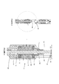
- Figure 3 is a longitudinal section side view of the flow promotion device fitted between the protector and pump inlet.
- Figure 4 is a more detailed section side view of the flow promotion device shown in figure 3.
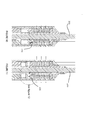
- Figure 5 is a longitudinal section side view of a canned motor with the filter inlet/outlets fitted at its upper and lower ends.
- Figure 6 is a more detailed section side view of output end of the motor shown in figure 5.
- Figure 7 is a more detailed section side view of the lower end of the motor shown in figure 5.
- Figure 8 is a similar view to figure 3 with the pump section above the flow promotion device highlighted.
- Figure 9 is a more detailed section side view of the part highlighted in figure 8.
- Figure 10 is a section side view of the back flush mechanism
- Figure 11 is a similar view to figure 9, with the back flush in operation
- Figure 12 is a more detailed of the back flush mechanism shown in the view indicated of figure 11
- the present invention generally relates to a system and method for reducing detrimental effects of sand on motor protectors.
- the system and method are useful with, for example, a variety of downhole production systems, such
- Pumping system 10 may comprise a variety of components depending on the particular application or environment in which it is used. In this example, however, pumping system 10 includes a submersible pump 12, a submersible motor 14 and a motor protector 16.
- Pumping system 10 is designed for deployment in a well 18 within a geological formation 20 containing desirable production fluids, such as water or petroleum.
- a wellbore 22 typically is drilled and lined with a wellbore casing 24.
- Wellbore casing 24 includes a plurality of openings or perforations 26 through which production fluids flow from formation 20 into wellbore 22.
- deployment system 28 may comprise tubing, such as coil tubing or production tubing, connected to pump 12 by a connector 32. Power is provided to submersible motor 14 via a power cable 34. Motor 14, in turn, powers pump 12 which draws production fluid in through a pump intake 36, and pumps the production fluid to the surface via tubing 30.
- submersible pumping system 10 is merely an example. Other components can be added to this system and other deployment systems may be implemented. Additionally, the production fluids may be pumped to the surface through tubing 30 or through the annulus formed between deployment system 28 and wellbore casing 24. In any of the many potential configurations of submersible pumping system 10, motor protector 16 is used to seal the submersible motor 14 from well fluid in wellbore 22 and to generally balance the internal pressure within submersible motor 14 with the external pressure in wellbore 22.
- Motor protector 16 comprises an outer housing 38 within which a drive shaft 40 is rotatably mounted via a plurality of bearings 42, such as journal bearings.
- Outer housing 38 may be formed of one or more housing components.
- the motor protector 16 is divided into a plurality of sections, including a head section 44 disposed generally at an upper end of the protector.
- An additional section (or sections) is disposed below head section 44 and functions as a fluid separation section to separate wellbore fluid that may enter head section 44 from internal motor oil used to lubricate submersible motor 14.
- the sections also facilitate balancing of internal and external pressures.
- a labyrinth section 46 is disposed below head section 44, and a pair of elastomeric bag sections 48 are disposed below labyrinth section 46.
- Labyrinth section 46 comprises a labyrinth 50 that uses the difference in specific gravity of the well fluid and the internal motor oil to maintain separation between the internal motor oil and the well fluid.
- Each bag section uses an elastomeric bag 52 to physically isolate the internal motor oil from the well fluid.
- the motor protector sections may comprise a variety of section types.
- the motor protector may comprise one or more labyrinth sections, one or more elastomeric bag sections, combinations of labyrinth and bag sections as well as other separation systems.
- a series of fluid ports or channels 54 connect each section with the next sequential section. In the embodiment illustrated, a port 54 is disposed between head section 44 and labyrinth section 46, between labyrinth section 46 and the next sequential bag section 48, between bag sections 48 and between the final bag section 48 and a lower end 56 of motor protector 16.
- Motor protector 16 may comprise a variety of additional features.
- a thrust bearing 58 may be deployed proximate lower end 56 to absorb axial loads placed on shaft 40 by the pumping action of submersible pump 12.
- the protector also may comprise an outward relief mechanism 60, such as an outward relief valve.
- the outward relief valve releases excessive internal pressure that may build up during, for example, the heating cycle that occurs with start-up of electric submersible pumping system 10.
- Motor protector 16 also may comprise an inward relief mechanism 62, such as an inward relief valve.
- the inward relief valve relieves excessive negative pressure within the motor protector.
- Inward relief mechanism 62 alleviates the excessive negative pressure by, for example, releasing external fluid into the motor protector to reduce or avoid mechanical damage to the system caused by this excessive negative pressure.
- the output shaft from the protector 100 passing through the assembly 101 the shaft 100 is supported in bearings 102 and 103, and drives the pump via splined output 104 via coupling 105.
- the pump inlet is shown as passages 106. In the event the pump is stopped and sand particles fall out of suspension, they will contact the deflector 107 mounted on the shaft, fall on the sloping surface 108 and fall into the annulus around the pump.
- a canned motor assembly This is where the stator 120 is physically isolated from the rotor cavity 122 by a tube 124. This is particularly advantageous with this invention, as the protector can be eliminated.
- the thrust bearing assembly 114 At the output end above the thrust bearing assembly 114 is an identical mechanism 125 described in relation to figure 4.
- the rotor cavity 115 is equalised with the fluid around the outside of the motor via a filter medium 117 and ports 118 and 119.
- the filter medium can be selected to filter any particle size and have sufficiently volume to have a predicable long life.
- the filter medium could be made of different layers with different filtering capabilities.
- the bearing inside the rotor cavity should be capable of running in either oil or water and made from a suitable material such as tungsten carbide.
- the flow outlet from the pressuring pump 112 exits from below the flow outlet protector 107 via a narrower channel 130, and also exits via port 131 into a centre bore of the pump drive shaft 132.
- the coupling 133 there are o-rings 134 and 135 which seal on respective shafts 136 and 137, so the pressurised filtered fluid is pumped into a centre bore of the pump shaft 138.
- Some of the fluid exits the bore of pump shaft 138 through a port 139.
- a passage 140 allows filtered fluid to lubricate the pump bearing 141 before passing into the discharge fluid.
- Several bearings 141 having such passages 140 are distributed along the entire pump shaft length. This feature ensures a long bearing life, and a long endurance of the pump especially in a production fluid with sand other solid particles.
- This feature could also be used to supply clear fluids to drilling assembly bearings, and other systems exposed to abrasive fluids.
- a back flushing mechanism 220 there is shown a back flushing mechanism 220.
- a cam 200 reciprocates a piston 201 in a piston bore 202, clean fluid is fed into the piston bore 202 via passage 203, on each stroke of the piston 201 a small volume of fluid is displaced past the check valve 204 into the chamber 205.
- the annular piston 206 is displaced downwards against spring 207.
- a rod 208 attached to the piston unseats a valve 209 so that the collet fingers 216 and pushed out of recess 217 which allows the fluid accumulated in the chamber 210 to back flush the filter via passage 211 and check valve 212.
- the rotor shaft may include an additional pumping means, even a simple feature formed on the rotor shaft which tends to induce a fluid flow.
Landscapes
- Engineering & Computer Science (AREA)
- Mechanical Engineering (AREA)
- General Engineering & Computer Science (AREA)
- Mining & Mineral Resources (AREA)
- Life Sciences & Earth Sciences (AREA)
- Geology (AREA)
- Physics & Mathematics (AREA)
- Environmental & Geological Engineering (AREA)
- Fluid Mechanics (AREA)
- General Life Sciences & Earth Sciences (AREA)
- Geochemistry & Mineralogy (AREA)
- Structures Of Non-Positive Displacement Pumps (AREA)
Abstract
Priority Applications (2)
| Application Number | Priority Date | Filing Date | Title |
|---|---|---|---|
| GB1719797.1A GB2554612B (en) | 2015-04-28 | 2016-04-28 | Electrical submersible motor |
| US15/569,923 US20180149173A1 (en) | 2015-04-28 | 2016-04-28 | Electrical submersible motor |
Applications Claiming Priority (2)
| Application Number | Priority Date | Filing Date | Title |
|---|---|---|---|
| GBGB1507260.6A GB201507260D0 (en) | 2015-04-28 | 2015-04-28 | Electrical submersible motor |
| GB1507260.6 | 2015-04-28 |
Publications (1)
| Publication Number | Publication Date |
|---|---|
| WO2016174452A1 true WO2016174452A1 (fr) | 2016-11-03 |
Family
ID=53488814
Family Applications (1)
| Application Number | Title | Priority Date | Filing Date |
|---|---|---|---|
| PCT/GB2016/051225 Ceased WO2016174452A1 (fr) | 2015-04-28 | 2016-04-28 | Moteur électrique submersible |
Country Status (3)
| Country | Link |
|---|---|
| US (1) | US20180149173A1 (fr) |
| GB (2) | GB201507260D0 (fr) |
| WO (1) | WO2016174452A1 (fr) |
Cited By (1)
| Publication number | Priority date | Publication date | Assignee | Title |
|---|---|---|---|---|
| RU176533U1 (ru) * | 2017-01-09 | 2018-01-22 | Открытое акционерное общество "Сургутнефтегаз" | Модуль входной перепускной для УЭЦН |
Families Citing this family (8)
| Publication number | Priority date | Publication date | Assignee | Title |
|---|---|---|---|---|
| UA118287C2 (uk) * | 2016-12-14 | 2018-12-26 | Хачатуров Дмитро Валерійович | Заглибна насосна установка з лінійним електродвигуном і насосом подвійної дії |
| US20190264550A1 (en) * | 2018-02-23 | 2019-08-29 | Extract Production Services, LLC | Electric submersible pumping unit |
| RU189152U1 (ru) * | 2018-10-01 | 2019-05-14 | Акционерное общество "Самаранефтегаз" | Входной модуль-фильтр |
| US10961829B2 (en) * | 2019-02-14 | 2021-03-30 | Halliburton Energy Services, Inc. | Fallback bearing protection system |
| JP7233963B2 (ja) * | 2019-02-26 | 2023-03-07 | 三菱重工業株式会社 | ポンプ |
| JP2020197139A (ja) * | 2019-05-31 | 2020-12-10 | 三菱重工業株式会社 | 油田用ポンプ |
| CN112546694B (zh) * | 2020-11-23 | 2022-08-05 | 深圳市优贝尔科技有限公司 | 一种微型水过滤器 |
| WO2025213166A1 (fr) * | 2024-04-05 | 2025-10-09 | Schlumberger Technology Corporation | Conception d'élément de protection à grande vitesse |
Citations (3)
| Publication number | Priority date | Publication date | Assignee | Title |
|---|---|---|---|---|
| US5494109A (en) * | 1995-01-19 | 1996-02-27 | Stren Company | Backflush filter system for downhole pumps |
| US20090304526A1 (en) * | 2008-06-09 | 2009-12-10 | Michael Brent Ford | Debris removal apparatus for a pump and method |
| US20150064034A1 (en) * | 2013-08-27 | 2015-03-05 | Summit Esp, Llc | Modular intake filter system, apparatus and method |
-
2015
- 2015-04-28 GB GBGB1507260.6A patent/GB201507260D0/en not_active Ceased
-
2016
- 2016-04-28 US US15/569,923 patent/US20180149173A1/en not_active Abandoned
- 2016-04-28 GB GB1719797.1A patent/GB2554612B/en active Active
- 2016-04-28 WO PCT/GB2016/051225 patent/WO2016174452A1/fr not_active Ceased
Patent Citations (3)
| Publication number | Priority date | Publication date | Assignee | Title |
|---|---|---|---|---|
| US5494109A (en) * | 1995-01-19 | 1996-02-27 | Stren Company | Backflush filter system for downhole pumps |
| US20090304526A1 (en) * | 2008-06-09 | 2009-12-10 | Michael Brent Ford | Debris removal apparatus for a pump and method |
| US20150064034A1 (en) * | 2013-08-27 | 2015-03-05 | Summit Esp, Llc | Modular intake filter system, apparatus and method |
Cited By (1)
| Publication number | Priority date | Publication date | Assignee | Title |
|---|---|---|---|---|
| RU176533U1 (ru) * | 2017-01-09 | 2018-01-22 | Открытое акционерное общество "Сургутнефтегаз" | Модуль входной перепускной для УЭЦН |
Also Published As
| Publication number | Publication date |
|---|---|
| GB201719797D0 (en) | 2018-01-10 |
| US20180149173A1 (en) | 2018-05-31 |
| GB2554612A (en) | 2018-04-04 |
| GB201507260D0 (en) | 2015-06-10 |
| GB2554612B (en) | 2021-12-29 |
Similar Documents
| Publication | Publication Date | Title |
|---|---|---|
| WO2016174452A1 (fr) | Moteur électrique submersible | |
| US10711575B2 (en) | Well debris handling system | |
| US10683895B2 (en) | Systems and devices using hard bearings | |
| EP3449131B1 (fr) | Pompe d'injection d'eau lubrifiée de traitement sous-marine | |
| CA2414685C (fr) | Chambre de dissipation des gaz pour systemes de pompage a pompe submersible a tubage traversant | |
| US10801313B2 (en) | Motor and pump parts | |
| US9359875B2 (en) | Artificial lift tool | |
| US9777560B2 (en) | Auxiliary face seal for submersible well pump seal section | |
| US9303648B2 (en) | Compliant radial bearing for electrical submersible pump | |
| US10480522B2 (en) | Abrasion-resistant thrust ring for use with a downhole electrical submersible pump | |
| AU2016251882B2 (en) | Circulation pump for cooling mechanical face seal of submersible well pump assembly | |
| CA3078439C (fr) | Separateur de solides pour reduire ou eliminer la quantite de matieres en suspension | |
| US2733663A (en) | Deep well pumping apparatus | |
| RU2686811C1 (ru) | Погружная насосная установка | |
| RU2725202C1 (ru) | Погружная насосная установка для закачки жидкости |
Legal Events
| Date | Code | Title | Description |
|---|---|---|---|
| 121 | Ep: the epo has been informed by wipo that ep was designated in this application |
Ref document number: 16722921 Country of ref document: EP Kind code of ref document: A1 |
|
| WWE | Wipo information: entry into national phase |
Ref document number: 15569923 Country of ref document: US |
|
| NENP | Non-entry into the national phase |
Ref country code: DE |
|
| ENP | Entry into the national phase |
Ref document number: 201719797 Country of ref document: GB Kind code of ref document: A Free format text: PCT FILING DATE = 20160428 |
|
| 122 | Ep: pct application non-entry in european phase |
Ref document number: 16722921 Country of ref document: EP Kind code of ref document: A1 |