WO2016174703A1 - Dispositif de détection de défaut de câble métallique - Google Patents
Dispositif de détection de défaut de câble métallique Download PDFInfo
- Publication number
- WO2016174703A1 WO2016174703A1 PCT/JP2015/062648 JP2015062648W WO2016174703A1 WO 2016174703 A1 WO2016174703 A1 WO 2016174703A1 JP 2015062648 W JP2015062648 W JP 2015062648W WO 2016174703 A1 WO2016174703 A1 WO 2016174703A1
- Authority
- WO
- WIPO (PCT)
- Prior art keywords
- wire rope
- guide
- flaw detector
- guide member
- guide plate
- Prior art date
- Legal status (The legal status is an assumption and is not a legal conclusion. Google has not performed a legal analysis and makes no representation as to the accuracy of the status listed.)
- Ceased
Links
Images





Classifications
-
- G—PHYSICS
- G01—MEASURING; TESTING
- G01N—INVESTIGATING OR ANALYSING MATERIALS BY DETERMINING THEIR CHEMICAL OR PHYSICAL PROPERTIES
- G01N27/00—Investigating or analysing materials by the use of electric, electrochemical, or magnetic means
- G01N27/72—Investigating or analysing materials by the use of electric, electrochemical, or magnetic means by investigating magnetic variables
- G01N27/82—Investigating or analysing materials by the use of electric, electrochemical, or magnetic means by investigating magnetic variables for investigating the presence of flaws
- G01N27/83—Investigating or analysing materials by the use of electric, electrochemical, or magnetic means by investigating magnetic variables for investigating the presence of flaws by investigating stray magnetic fields
- G01N27/87—Investigating or analysing materials by the use of electric, electrochemical, or magnetic means by investigating magnetic variables for investigating the presence of flaws by investigating stray magnetic fields using probes
-
- G—PHYSICS
- G01—MEASURING; TESTING
- G01N—INVESTIGATING OR ANALYSING MATERIALS BY DETERMINING THEIR CHEMICAL OR PHYSICAL PROPERTIES
- G01N27/00—Investigating or analysing materials by the use of electric, electrochemical, or magnetic means
- G01N27/72—Investigating or analysing materials by the use of electric, electrochemical, or magnetic means by investigating magnetic variables
- G01N27/82—Investigating or analysing materials by the use of electric, electrochemical, or magnetic means by investigating magnetic variables for investigating the presence of flaws
- G01N27/83—Investigating or analysing materials by the use of electric, electrochemical, or magnetic means by investigating magnetic variables for investigating the presence of flaws by investigating stray magnetic fields
Definitions
- the present invention relates to a wire rope flaw detector that detects damage to a wire rope that suspends a passenger car such as an elevator.
- a wire rope flaw detector for detecting breakage of a wire rope such as an elevator and disconnection of an element wire
- a leakage magnetic flux generated in a damaged portion is detected by a detection coil when the wire rope is magnetically saturated.
- a wire rope including a magnet plate, a magnetic path material that bypasses the leakage flux to the outside of the wire rope, and a detection coil in order to efficiently supplement the leakage flux, and a guide plate having a U-shaped portion for the wire rope to travel.
- a flaw detection device is disclosed (for example, Patent Document 1).
- a positioning mechanism having a rotating contact portion that comes into contact with the wire rope so as to surround the outer periphery of the wire rope at three locations, and a force generating means that generates a force for the contact portion to closely contact the wire rope.
- a wire rope flaw detector provided with (for example, Patent Document 2).
- Patent Document 1 if the use is continued, a notch is generated at the end portion of the guide plate due to rubbing with the wire rope, causing a vibration of the wire rope and causing a problem in detecting a damaged portion.
- the invention disclosed in Patent Document 2 includes a mechanism for reducing the vibration of the wire rope.
- the structure is complicated, there is a problem that a great deal of labor is required to replace parts when the mechanism is damaged.
- the present invention has been made to solve the above-described problems, and it is an object of the present invention to provide a wire rope flaw detector that can suppress vibration of a wire rope with a simple configuration and that can easily replace consumable parts. To do.
- a wire rope flaw detector includes a magnetizer that forms a main magnetic path in the axial direction of a wire rope and a magnetic sensor that detects a leakage magnetic flux generated by a damaged portion of the wire rope magnetized by the magnetizer. And a guide member and a guide plate formed in a U-shape so as to follow the outer periphery of the wire rope on the side facing the wire rope, the guide plate being disposed above the magnetizer and the magnetic sensor, Is arranged on both outer sides in the wire rope axial direction of the guide plate, the guide member is constituted by a guide unit fixed to the guide plate, and the guide unit is fixed to the base unit by fixing means.
- the guide member and the guide plate are formed in a U shape so as to follow the outer periphery of the wire rope, and the guide unit is fixed to the base unit by the fixing means.
- the configuration can suppress the vibration of the wire rope and can easily replace the consumable parts.
- Embodiment 1 FIG.
- a magnetizer that forms a main magnetic path in a wire rope
- a base unit that includes a magnetic sensor that detects a leakage magnetic flux generated by a damaged portion of the wire rope
- a U-shape along the outer periphery of the wire rope The present invention relates to a wire rope flaw detector comprising a guide member and a guide unit comprising a guide plate. Furthermore, the U-shaped part of the guide member is formed of a thick member, the inner side surface is formed so as to spread outward, and the guide unit is fixed to the base unit with bolts.
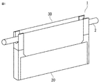
- FIG. 1 is a perspective view of a wire rope flaw detector 1 according to Embodiment 1 of the present invention, and also shows a wire rope 2 to be inspected.
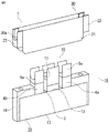
- FIG. 2 is a perspective view showing a state in which the guide unit 30 at the top of the wire rope flaw detector 1 is removed.
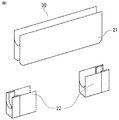
- FIG. 3 is a perspective view in which the guide unit 30 is separated into a guide plate 21 and a guide member 22.
- 4 and 5 are a structural view and a cross-sectional view for explaining the structure of the guide member 22.
- FIG. 6 is a drawing for explaining a method of assembling and fixing the wire rope flaw detector 1.
- FIG. 7 is a structural diagram for explaining the positioning structure of the guide member 22.
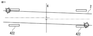
- 8 to 11 are diagrams for explaining the effects of the wire rope flaw detector 1 according to the first embodiment, and are schematic views of a wire rope flaw detector of a reference example.
- the wire rope flaw detector 1 includes a base unit 20 and a guide unit 30, and the guide unit 30 is fixed to the base unit 20 with bolts as will be described later.
- the wire rope 2 to be inspected travels in a substantially U-shaped portion 30 a at the top of the guide unit 30.
- the guide unit 30 includes a guide plate 21 and a guide member 22.
- the base unit 20 includes a main circuit unit 15, a support column 16, and a base cover 17.
- the main circuit unit 15 includes a magnetizer 10, a magnetic sensor 11, and a support base 12 for the magnetic sensor 11.
- the magnetizer 10 includes a back yoke 3, permanent magnets 4a and 4b, and magnetic pole pieces 5a and 5b.
- the wire rope flaw detector 1 of the first embodiment forms a main magnetic path in a predetermined axial section of the wire rope 2 traveling by the magnetizer 10, and breaks the wire rope 2 and breaks the wire (hereinafter referred to as wire).
- the magnetic flux detected by the magnetic sensor 11 is detected by the magnetic sensor 11.
- the magnetizer 10 is disposed on the both ends of the back yoke 3 made of a ferromagnetic material such as iron and with opposite polarities.
- a pair of exciting permanent magnets 4a and 4b and magnetic pole pieces 5a and 5b made of a ferromagnetic material disposed on the magnetic pole surface opposite to the back yoke 3 of each permanent magnet 4a and 4b are provided.
- the pole pieces 5 a and 5 b are substantially U-shaped so that the upper portions thereof are along the outer periphery of the wire rope 2.
- Support columns 16 are disposed at both ends of the back yoke 3 of the magnetizer 10, and guide members 22 are disposed above the support columns 16.
- the support column 16 and the back yoke 3 of the main circuit portion 15 are fitted into each other and fixed with bolts.
- the base cover 17 is provided to protect a signal processing circuit unit (not shown) that processes a signal detected by the magnetic sensor 11 provided in the main circuit unit 15.
- the guide unit 30 will be described.
- the guide member 22 is disposed outside the magnetic pole pieces 5a and 5b in the wire rope axial direction. Similar to the magnetic pole pieces 5a and 5b, the upper portion of the guide member 22 is formed in a substantially U shape so as to follow the outer periphery of the wire rope 2 as with the magnetic pole pieces 5a and 5b.
- the guide plate 21 is made of a non-magnetic material such as stainless steel, and is disposed so as to be in close contact with the U-shaped section of the magnetic pole pieces 5a and 5b.
- the guide plate 21 is disposed above the magnetizer 10 and the magnetic sensor 11 and has a function of protecting the magnetic pole pieces 5 a and 5 b and the magnetic sensor 11. Furthermore, the guide plate 21 fulfills a guide function for smoothly running the wire rope 2.
- the substantially U-shaped portion formed along the outer periphery of the wire rope 2 on the upper portion of the guide plate 21 and the guide member 22 is collectively referred to as 30 a.
- FIG. 4A is a front view of the guide member 22
- FIG. 4B is a side view
- FIG. 4C is a top view
- FIG. 5A is a diagram for explaining the arrangement relationship with the guide plate 21, and
- FIG. 5B is a cross-sectional view taken along the line AA of FIG. Is shown.
- the upper portion 22d of the substantially U-shaped portion of the guide member 22 is formed of a member (thickness t1) thicker than the plate thickness (t2) of the guide plate 21. Further, the inner side surface 22e of the end portion in the wire rope axial direction of the guide member 22 is formed so as to spread outward in the wire rope radial direction.
- the thickness (t3) of the portion where the guide member 22 is in contact with the wire rope 2 is formed in a predetermined amount (1 mm to 2 mm) in consideration of the entire size of the wire rope flaw detector 1.
- the guide member 22 includes a cover storing step 22 a.
- the depth of the cover storing step 22 a is set slightly deeper than the thickness of the guide plate 21. As shown in FIG.
- the guide plate 21 is disposed in contact with the cover storing step 22 a of the guide member 22. For this reason, the guide member 22 is disposed in a state of protruding outward in the wire rope axial direction from the guide plate 21. Specifically, in FIG. 5A, the guide member 22 is arranged in a state of projecting outward in the wire rope axial direction on the right side of the guide plate 21. Further, as shown in FIG. 5B, a fixing bolt hole 22 b and a positioning hole 22 c are provided in the lower portion of the guide member 22.
- the assembly procedure of the wire rope flaw detector 1, specifically, the assembly and fixing procedure of the base unit 20 and the guide unit 30 will be described with reference to FIG. 6.
- the base cover 17 of the base unit 20 and the guide plate 21 of the guide unit 30 are omitted for easy understanding.
- FIG. 6A is a front view showing a state when the guide member 22 of the guide unit 30 and the support column 16 of the base unit 20 are removed.
- FIG. 6B is a front view showing a state in which the support column 16 is fixed to the back yoke 3 of the main circuit unit 15 from the state of FIG.
- the concave portion 16 a provided in the support column 16 is fitted into the convex portion 3 a of the back yoke 3 of the main circuit portion 15 and fixed with a bolt. Since the post 16 is counterbored, the head of the bolt is located closer to the back yoke 3 than another bolt hole that is orthogonal.
- the guide member 22 of the guide unit 30 is fixed to the support column 16 of the base unit 20 by bolts from below. Thereby, the guide unit 30 is fixed to the main circuit unit 15 including the magnetizer 10, the magnetic sensor 11, the support 12 of the magnetic sensor 11, and the back yoke 3.
- the guide member 22 of the guide unit 30 and the column 16 of the base unit 20 are positioned by the positioning hole 22c of the guide member 22 and the positioning pin 16c of the column 16.
- the column 16 is provided with a recess and the back circuit 3 of the main circuit unit 15 is provided with a projection.
- the column 16 is provided with a projection and the back part 3 of the main circuit unit 15 is provided with a projection. You may provide a recessed part in.
- the positioning hole is provided in the guide member 22 of the guide unit 30 and the positioning pin is provided in the support column 16 of the base unit 20, the positioning pin may be provided in the guide member 22 and the positioning hole may be provided in the support column 16. .
- the bolts fixing the support column 16 and the back yoke 3 of the main circuit portion 15 The guide member 22 of the guide unit 30 and the bolt fixing the support column 16 of the base unit 20 do not interfere with each other.
- pillar 16, and the guide member 22 of the guide unit 30 are comprised as mentioned above, the base unit 20 provided with the guide unit 30 and the main circuit part 15 is bolted. It becomes possible to fix with. For this reason, even if the guide member 22 and the guide plate 21 are rubbed and worn against the wire rope 2, only the guide unit 30 may be replaced by removing the bolts.
- the bolt is used as the means for fixing the guide unit 30 to the base unit 20.
- the bolt may be used. It is not limited.
- FIG. 7 shows an example in which another means is used for positioning the guide member 22 of the guide unit 30 according to the first embodiment and the support column 16 of the base unit 20.
- positioning structures 122 d and 116 e are formed on the guide member 122 and the column 116. Specifically, a convex portion 122 d is formed at the lower portion of the guide member 122, and a concave portion 116 e is formed at the upper portion of the support column 116.
- the guide member 122 of the guide unit is provided with a protrusion and the support 116 of the base unit is provided with a recess.
- the guide member 122 is provided with a recess and the support 116 is provided with a protrusion. May be.
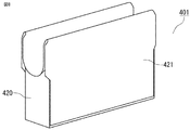
- FIG. 8 is a perspective view showing a wire rope flaw detector 401 of a reference example
- FIG. 9 is a perspective view showing a state in which the guide plate 421 of the wire rope flaw detector 401 is removed.
- the guide plate 421 of the wire rope flaw detector 401 of the reference example is disposed so as to cover the base unit 420 and is fixed to the base unit 420 with an adhesive.
- the guide plate 421 is formed to extend outward in the wire rope axial direction from the base unit 420. For this reason, the guide plate 421 receives all contact between the wire rope and the wire rope flaw detector 401. Further, the end portion of the guide plate 421 is flared to avoid the wire rope strand from being caught.
- the end of the guide plate 421 in the wire rope axial direction is worn by sliding with the wire rope, and a notch 450 as shown in FIG. 10 is formed.
- the notch 450 becomes larger, the edge portion of the notch 450 bites into the valleys of the wire rope strands. This causes vibration and adversely affects detection of leakage magnetic flux.
- vibration increases, there is a moment when the distance between the wire rope and the magnetic sensor increases. At this moment, the magnetic flux leakage becomes small and normal detection of the damaged portion of the wire rope becomes impossible.
- the wire rope flaw detector 1 of the present invention on the problems of the wire rope flaw detector of the reference example described above will be described.
- the portion where the wire rope 2 and the guide unit 30 are in contact is formed so that the guide member 22 is an end. For this reason, even if wear due to sliding of the wire rope 2 occurs, the guide plate 21 is not cut out. For this reason, generation
- the guide member 22 includes a cover storing step 22 a, and the depth of the cover storing step 22 a is set slightly deeper than the thickness of the guide plate 21. For this reason, the level
- the wire rope flaw detector 1 according to Embodiment 1 is used for a wire rope 2 that suspends a passenger car such as an elevator. Since the end portions of the two guide members 22 arranged at both ends of the wire rope flaw detector 1 are formed so as to spread outward, there is no problem even if the wire rope 2 travels in either direction. It has no structure.
- the wire rope 2 is not strongly pressed against the end of the guide unit 30.
- the guide member 22 of the guide unit 30 when the guide member 22 of the guide unit 30 is worn as a result of installing the wire rope flaw detector 1 for inspection with respect to the wire rope 2 for suspending the elevator car or the like and conducting the wire rope flaw inspection, the guide The guide unit 30 can be replaced as a consumable part by removing only the unit 30 from the bolt.
- the wire rope flaw detector according to Embodiment 1 includes a magnetizer that forms a main magnetic path in the wire rope, and a base unit that includes a magnetic sensor that detects leakage magnetic flux generated by the damaged portion of the wire rope. It is comprised from the guide unit provided with the guide member formed in U shape so that the outer periphery of a wire rope may be followed, and a guide plate. Further, the upper portion of the U-shaped portion of the guide member is formed of a thick member, the inner side surface is formed so as to spread outward, and the guide unit is fixed to the base unit with bolts. Therefore, the wire rope flaw detector according to Embodiment 1 can suppress the vibration of the wire rope with a simple configuration and can easily replace the consumable parts.
- the wire rope flaw detector of Embodiment 1 has a simple configuration, and the guide unit is fixed to the base unit with bolts, so that it is possible to extend the life and facilitate disassembly.
- Embodiment 2 In the wire rope flaw detector according to Embodiment 2, a guide plate and a guide member are fixed by welding.
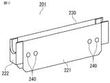
- FIG. 12 is a perspective view of a guide unit of the wire rope flaw detector.
- the wire rope flaw detector 201 includes a guide unit 230 and a base unit (not shown).
- the guide unit 230 includes a guide plate 221 and a guide member 222.
- the guide plate 221 and the guide member 222 are fixed by welding 240.
- the guide plate 21 and the guide member 22 are fixed by bonding.
- the same effect as the wire rope flaw detector 1 of the first embodiment is obtained.
- the fixing strength between the guide plate 221 and the guide member 222 is higher than that in the case of bonding, and the wire rope flaw detector 201 with high mechanical rigidity is obtained.
- the wire rope flaw detector according to Embodiment 2 configures the guide unit 230 by fixing the guide plate and the guide member by welding. Therefore, similarly to the wire rope flaw detector according to the first embodiment, vibration of the wire rope can be suppressed with a simple configuration, and consumable parts can be easily replaced. Moreover, the wire rope flaw detector according to Embodiment 2 can increase the mechanical rigidity of the guide unit.
- Embodiment 3 In the wire rope flaw detector according to Embodiment 3, a guide plate and a guide member are fixed with bolts.
- FIG. 13 is a perspective view of a guide unit of the wire rope flaw detector.
- a wire rope flaw detector 301 includes a guide unit 330 and a base unit (not shown).
- the guide unit 330 includes a guide plate 321 and a guide member 322.
- the guide plate 321 and the guide member 322 are fixed with bolts 340.
- the guide plate 21 and the guide member 22 are fixed by bonding.
- the same effect as the wire rope flaw detector 1 of the first embodiment is obtained. Can be obtained.
- the guide plate 321 and the guide member 322 are simply fixed by the bolt, the productivity of the wire rope flaw detector 301 can be increased.
- the guide plate 321 and the guide member 322 can be separated by removing the bolt 340, for example, only the worn guide member 322 can be replaced.
- the wire rope flaw detector according to Embodiment 3 has a guide plate and a guide member fixed with bolts. Therefore, similarly to the wire rope flaw detector according to the first embodiment, vibration of the wire rope can be suppressed with a simple configuration, and consumable parts can be easily replaced. Further, since the wire rope flaw detector of Embodiment 3 can easily fix and remove the guide plate and the guide member, the productivity of the wire rope flaw detector can be further improved and disassembly can be facilitated.
- the present invention relates to a wire rope flaw detector that can suppress vibration of a wire rope with a simple configuration and can easily replace consumable parts, and can be widely applied to a wire rope inspection device.
Landscapes
- Chemical & Material Sciences (AREA)
- Chemical Kinetics & Catalysis (AREA)
- Electrochemistry (AREA)
- Physics & Mathematics (AREA)
- Health & Medical Sciences (AREA)
- Life Sciences & Earth Sciences (AREA)
- Analytical Chemistry (AREA)
- Biochemistry (AREA)
- General Health & Medical Sciences (AREA)
- General Physics & Mathematics (AREA)
- Immunology (AREA)
- Pathology (AREA)
- Investigating Or Analyzing Materials By The Use Of Magnetic Means (AREA)
Abstract
Priority Applications (6)
| Application Number | Priority Date | Filing Date | Title |
|---|---|---|---|
| JP2017515295A JP6381791B2 (ja) | 2015-04-27 | 2015-04-27 | ワイヤロープ探傷装置 |
| CN201580079255.4A CN107636456B (zh) | 2015-04-27 | 2015-04-27 | 缆绳探伤装置 |
| KR1020177030798A KR101970096B1 (ko) | 2015-04-27 | 2015-04-27 | 와이어 로프 탐상 장치 |
| PCT/JP2015/062648 WO2016174703A1 (fr) | 2015-04-27 | 2015-04-27 | Dispositif de détection de défaut de câble métallique |
| US15/564,113 US10571429B2 (en) | 2015-04-27 | 2015-04-27 | Wire rope flaw detection device |
| DE112015006493.1T DE112015006493B4 (de) | 2015-04-27 | 2015-04-27 | Vorrichtung zum detektieren von drahtseilbeschädigungen |
Applications Claiming Priority (1)
| Application Number | Priority Date | Filing Date | Title |
|---|---|---|---|
| PCT/JP2015/062648 WO2016174703A1 (fr) | 2015-04-27 | 2015-04-27 | Dispositif de détection de défaut de câble métallique |
Publications (1)
| Publication Number | Publication Date |
|---|---|
| WO2016174703A1 true WO2016174703A1 (fr) | 2016-11-03 |
Family
ID=57198220
Family Applications (1)
| Application Number | Title | Priority Date | Filing Date |
|---|---|---|---|
| PCT/JP2015/062648 Ceased WO2016174703A1 (fr) | 2015-04-27 | 2015-04-27 | Dispositif de détection de défaut de câble métallique |
Country Status (6)
| Country | Link |
|---|---|
| US (1) | US10571429B2 (fr) |
| JP (1) | JP6381791B2 (fr) |
| KR (1) | KR101970096B1 (fr) |
| CN (1) | CN107636456B (fr) |
| DE (1) | DE112015006493B4 (fr) |
| WO (1) | WO2016174703A1 (fr) |
Cited By (1)
| Publication number | Priority date | Publication date | Assignee | Title |
|---|---|---|---|---|
| WO2018110039A1 (fr) * | 2016-12-13 | 2018-06-21 | 三菱電機株式会社 | Détecteur de défauts de câble métallique |
Families Citing this family (7)
| Publication number | Priority date | Publication date | Assignee | Title |
|---|---|---|---|---|
| KR102322952B1 (ko) * | 2018-01-29 | 2021-11-05 | 미쓰비시덴키 가부시키가이샤 | 와이어 로프 탐상 장치의 출력 확인 장치 |
| KR102403602B1 (ko) * | 2020-08-19 | 2022-05-31 | (주)엔키아 | 배터리팩을 이용하여 체결 가능한 와이어로프 진단 장치 |
| CN112326781A (zh) * | 2021-01-04 | 2021-02-05 | 四川大学 | 一种轴承滚针漏磁检测装置 |
| KR102278029B1 (ko) * | 2021-02-19 | 2021-07-15 | 김민성 | 제강 산업의 비파괴 검사용 자속 탐상장치 |
| USD1011208S1 (en) * | 2021-10-08 | 2024-01-16 | Nkia Co., Ltd. | Movable wire rope safety diagnostic device |
| USD1018328S1 (en) * | 2022-04-11 | 2024-03-19 | Hach Company | Sensor cleaning and calibration system housing |
| WO2026067976A1 (fr) * | 2024-09-26 | 2026-04-02 | Dywidag-Systems International Gmbh | Dispositif d'inspection de défauts de câble métallique |
Citations (7)
| Publication number | Priority date | Publication date | Assignee | Title |
|---|---|---|---|---|
| JPS50156089U (fr) * | 1974-06-11 | 1975-12-24 | ||
| JPS61146763U (fr) * | 1985-03-05 | 1986-09-10 | ||
| JPH0518939A (ja) * | 1991-07-08 | 1993-01-26 | Hitachi Building Syst Eng & Service Co Ltd | ワイヤーロープの磁気探傷装置 |
| JP2002181792A (ja) * | 2000-12-15 | 2002-06-26 | Hitachi Building Systems Co Ltd | ワイヤーロープの損傷検出装置 |
| JP2005089172A (ja) * | 2003-09-19 | 2005-04-07 | Toshiba Elevator Co Ltd | ロープテスタ |
| JP2010256110A (ja) * | 2009-04-23 | 2010-11-11 | Mitsubishi Electric Corp | ロープテスター |
| JP2012021857A (ja) * | 2010-07-14 | 2012-02-02 | Mitsubishi Electric Corp | ロープテスタ |
Family Cites Families (9)
| Publication number | Priority date | Publication date | Assignee | Title |
|---|---|---|---|---|
| JPS56148052A (en) * | 1980-04-21 | 1981-11-17 | Hitachi Elevator Eng & Serv Co Ltd | Electromagnetic flaw detector for continuous magnetic material |
| JPH09210968A (ja) | 1996-02-06 | 1997-08-15 | Electron Kiyooto:Kk | ワイヤーロープの損傷検出器 |
| US8536861B2 (en) * | 2007-01-31 | 2013-09-17 | Mitsubishi Electric Corporation | Wire rope flaw detector |
| DE112007003297B4 (de) * | 2007-01-31 | 2015-05-21 | Mitsubishi Electric Corp. | Drahtseildefektdetektor |
| JP5031528B2 (ja) * | 2007-11-19 | 2012-09-19 | 株式会社日立製作所 | ワイヤーロープの探傷装置 |
| JP4638935B2 (ja) | 2008-12-03 | 2011-02-23 | 株式会社日立ビルシステム | ワイヤーロープの探傷装置 |
| JP4686612B2 (ja) * | 2009-01-22 | 2011-05-25 | 三菱電機株式会社 | ワイヤロープ探傷装置 |
| US9075023B2 (en) * | 2011-06-07 | 2015-07-07 | Mitsubishi Electric Corporation | Wire rope flaw detector |
| WO2014016978A1 (fr) * | 2012-07-27 | 2014-01-30 | 東京製綱株式会社 | Dispositif de détection de dommage |
-
2015
- 2015-04-27 KR KR1020177030798A patent/KR101970096B1/ko active Active
- 2015-04-27 WO PCT/JP2015/062648 patent/WO2016174703A1/fr not_active Ceased
- 2015-04-27 CN CN201580079255.4A patent/CN107636456B/zh active Active
- 2015-04-27 DE DE112015006493.1T patent/DE112015006493B4/de active Active
- 2015-04-27 JP JP2017515295A patent/JP6381791B2/ja active Active
- 2015-04-27 US US15/564,113 patent/US10571429B2/en not_active Expired - Fee Related
Patent Citations (7)
| Publication number | Priority date | Publication date | Assignee | Title |
|---|---|---|---|---|
| JPS50156089U (fr) * | 1974-06-11 | 1975-12-24 | ||
| JPS61146763U (fr) * | 1985-03-05 | 1986-09-10 | ||
| JPH0518939A (ja) * | 1991-07-08 | 1993-01-26 | Hitachi Building Syst Eng & Service Co Ltd | ワイヤーロープの磁気探傷装置 |
| JP2002181792A (ja) * | 2000-12-15 | 2002-06-26 | Hitachi Building Systems Co Ltd | ワイヤーロープの損傷検出装置 |
| JP2005089172A (ja) * | 2003-09-19 | 2005-04-07 | Toshiba Elevator Co Ltd | ロープテスタ |
| JP2010256110A (ja) * | 2009-04-23 | 2010-11-11 | Mitsubishi Electric Corp | ロープテスター |
| JP2012021857A (ja) * | 2010-07-14 | 2012-02-02 | Mitsubishi Electric Corp | ロープテスタ |
Cited By (6)
| Publication number | Priority date | Publication date | Assignee | Title |
|---|---|---|---|---|
| WO2018110039A1 (fr) * | 2016-12-13 | 2018-06-21 | 三菱電機株式会社 | Détecteur de défauts de câble métallique |
| JPWO2018110039A1 (ja) * | 2016-12-13 | 2019-06-24 | 三菱電機株式会社 | ワイヤーロープ探傷装置 |
| KR20190077497A (ko) * | 2016-12-13 | 2019-07-03 | 미쓰비시덴키 가부시키가이샤 | 와이어 로프 탐상 장치 |
| CN110073209A (zh) * | 2016-12-13 | 2019-07-30 | 三菱电机株式会社 | 缆绳探伤装置 |
| KR102180650B1 (ko) | 2016-12-13 | 2020-11-19 | 미쓰비시덴키 가부시키가이샤 | 와이어 로프 탐상 장치 |
| US11117785B2 (en) | 2016-12-13 | 2021-09-14 | Mitsubishi Electric Corporation | Wire rope flaw detector |
Also Published As
| Publication number | Publication date |
|---|---|
| JP6381791B2 (ja) | 2018-08-29 |
| US20180080901A1 (en) | 2018-03-22 |
| KR101970096B1 (ko) | 2019-04-17 |
| KR20170136547A (ko) | 2017-12-11 |
| CN107636456B (zh) | 2020-11-17 |
| JPWO2016174703A1 (ja) | 2017-09-14 |
| DE112015006493B4 (de) | 2023-08-03 |
| US10571429B2 (en) | 2020-02-25 |
| CN107636456A (zh) | 2018-01-26 |
| DE112015006493T5 (de) | 2018-01-18 |
Similar Documents
| Publication | Publication Date | Title |
|---|---|---|
| JP6381791B2 (ja) | ワイヤロープ探傷装置 | |
| JP4968859B2 (ja) | ワイヤロープ探傷装置 | |
| KR20160140355A (ko) | 로터 코어의 제조 방법, 로터의 제조 방법, 로터, 및 모터 | |
| US11117785B2 (en) | Wire rope flaw detector | |
| KR102027102B1 (ko) | 와이어 로프 탐상 장치 | |
| US20150236558A1 (en) | Electric motor having embedded permanent magnets | |
| WO2008093410A1 (fr) | Détecteur de défauts dans un câble en acier | |
| JPWO2012105261A1 (ja) | モータのステータおよびモータ | |
| US9780612B2 (en) | Rotor structure for electric rotating machine | |
| JP2016207687A (ja) | 磁気エンコーダの着磁装置 | |
| US20140354385A1 (en) | Magnetic circuit | |
| JP5982776B2 (ja) | 永久磁石形回転電機の回転子 | |
| JP6123716B2 (ja) | ロータ | |
| JP2010256110A (ja) | ロープテスター | |
| JP2011135728A (ja) | 磁石埋め込み型回転子 | |
| CN103314512A (zh) | 直线电动机的包装/安装夹具 | |
| JP6639688B2 (ja) | 永久磁石励磁型同期機の回転子および回転子のための磁極間スペーサ部材 | |
| TWI495228B (zh) | 磁鐵埋設型轉子 | |
| JP2020039231A (ja) | 締結構造 | |
| JP2017168707A (ja) | 磁気エンコーダの着磁装置および着磁方法 | |
| JP2014220968A (ja) | 永久磁石式電動機の回転子 | |
| HK1135182B (en) | Wire rope flaw detector | |
| JP2015228718A (ja) | 回転電機の固定子 |
Legal Events
| Date | Code | Title | Description |
|---|---|---|---|
| 121 | Ep: the epo has been informed by wipo that ep was designated in this application |
Ref document number: 15890687 Country of ref document: EP Kind code of ref document: A1 |
|
| ENP | Entry into the national phase |
Ref document number: 2017515295 Country of ref document: JP Kind code of ref document: A |
|
| WWE | Wipo information: entry into national phase |
Ref document number: 15564113 Country of ref document: US |
|
| ENP | Entry into the national phase |
Ref document number: 20177030798 Country of ref document: KR Kind code of ref document: A |
|
| WWE | Wipo information: entry into national phase |
Ref document number: 112015006493 Country of ref document: DE |
|
| 122 | Ep: pct application non-entry in european phase |
Ref document number: 15890687 Country of ref document: EP Kind code of ref document: A1 |