WO2016174912A1 - 金属ナトリウム封入エンジンバルブの製造方法及びその装置 - Google Patents
金属ナトリウム封入エンジンバルブの製造方法及びその装置 Download PDFInfo
- Publication number
- WO2016174912A1 WO2016174912A1 PCT/JP2016/055748 JP2016055748W WO2016174912A1 WO 2016174912 A1 WO2016174912 A1 WO 2016174912A1 JP 2016055748 W JP2016055748 W JP 2016055748W WO 2016174912 A1 WO2016174912 A1 WO 2016174912A1
- Authority
- WO
- WIPO (PCT)
- Prior art keywords
- hollow
- sodium
- metal sodium
- valve
- umbrella
- Prior art date
- Legal status (The legal status is an assumption and is not a legal conclusion. Google has not performed a legal analysis and makes no representation as to the accuracy of the status listed.)
- Ceased
Links
Images



Classifications
-
- F—MECHANICAL ENGINEERING; LIGHTING; HEATING; WEAPONS; BLASTING
- F01—MACHINES OR ENGINES IN GENERAL; ENGINE PLANTS IN GENERAL; STEAM ENGINES
- F01L—CYCLICALLY OPERATING VALVES FOR MACHINES OR ENGINES
- F01L3/00—Lift-valve, i.e. cut-off apparatus with closure members having at least a component of their opening and closing motion perpendicular to the closing faces; Parts or accessories thereof
- F01L3/12—Cooling of valves
- F01L3/14—Cooling of valves by means of a liquid or solid coolant, e.g. sodium, in a closed chamber in a valve
-
- B—PERFORMING OPERATIONS; TRANSPORTING
- B23—MACHINE TOOLS; METAL-WORKING NOT OTHERWISE PROVIDED FOR
- B23P—METAL-WORKING NOT OTHERWISE PROVIDED FOR; COMBINED OPERATIONS; UNIVERSAL MACHINE TOOLS
- B23P15/00—Making specific metal objects by operations not covered by a single other subclass or a group in this subclass
- B23P15/001—Making specific metal objects by operations not covered by a single other subclass or a group in this subclass valves or valve housings
- B23P15/002—Making specific metal objects by operations not covered by a single other subclass or a group in this subclass valves or valve housings poppet valves
-
- F—MECHANICAL ENGINEERING; LIGHTING; HEATING; WEAPONS; BLASTING
- F04—POSITIVE - DISPLACEMENT MACHINES FOR LIQUIDS; PUMPS FOR LIQUIDS OR ELASTIC FLUIDS
- F04B—POSITIVE-DISPLACEMENT MACHINES FOR LIQUIDS; PUMPS
- F04B37/00—Pumps having pertinent characteristics not provided for in, or of interest apart from, groups F04B25/00 - F04B35/00
- F04B37/02—Pumps having pertinent characteristics not provided for in, or of interest apart from, groups F04B25/00 - F04B35/00 for evacuating by absorption or adsorption
- F04B37/04—Selection of specific absorption or adsorption materials
-
- H—ELECTRICITY
- H05—ELECTRIC TECHNIQUES NOT OTHERWISE PROVIDED FOR
- H05B—ELECTRIC HEATING; ELECTRIC LIGHT SOURCES NOT OTHERWISE PROVIDED FOR; CIRCUIT ARRANGEMENTS FOR ELECTRIC LIGHT SOURCES, IN GENERAL
- H05B6/00—Heating by electric, magnetic or electromagnetic fields
- H05B6/02—Induction heating
- H05B6/10—Induction heating apparatus, other than furnaces, for specific applications
- H05B6/101—Induction heating apparatus, other than furnaces, for specific applications for local heating of metal pieces
-
- F—MECHANICAL ENGINEERING; LIGHTING; HEATING; WEAPONS; BLASTING
- F01—MACHINES OR ENGINES IN GENERAL; ENGINE PLANTS IN GENERAL; STEAM ENGINES
- F01L—CYCLICALLY OPERATING VALVES FOR MACHINES OR ENGINES
- F01L2303/00—Manufacturing of components used in valve arrangements
- F01L2303/01—Tools for producing, mounting or adjusting, e.g. some part of the distribution
Definitions
- the present invention relates to a method and an apparatus for manufacturing an engine valve in which metallic sodium is enclosed.
- Such an engine valve holds the umbrella portion at a temperature at which the metallic sodium is melted, while the wire-shaped metallic sodium is introduced into the hollow portion from the opening at the upper end of the stem portion. It has been proposed that metal sodium be supplied while being liquefied in the hollow portion by being fed into the container.
- an object of the present invention is to provide a manufacturing method and an apparatus for a metallic sodium filled engine valve that can be efficiently and continuously produced while facilitating temperature control.
- a method for manufacturing a metallic sodium-enclosed engine valve according to the first invention includes a hollow portion having a hollow portion inside a stem portion and an umbrella portion and having an opening at an upper end of the stem portion.
- a metal sodium-encapsulated engine valve manufacturing method in which metal sodium is sealed in the hollow portion by filling the hollow portion with metallic sodium from the opening of the stem portion of the stem portion. Inserting a rod-shaped metal sodium into the hollow portion of the hollow portion, and inserting a pressing rod from the opening into the hollow portion of the hollow valve into which the metal sodium has been inserted in the umbrella portion metallic sodium insertion step.
- the temperature is set to a temperature at which the metal sodium is melted.
- a melting step for melting the metallic sodium in the hollow portion by heating the portion, and a stem for cooling the stem portion of the hollow valve in which the metallic sodium is melted in the melting step to a temperature below the melting temperature for the metallic sodium A partial cooling step, and a stem sodium metal sodium insertion step of inserting rod-shaped metal sodium into the hollow portion of the hollow valve cooled in the stem cooling step.
- the method for manufacturing a metal sodium-enclosed engine valve according to the second aspect of the invention is the first aspect of the invention, in the hollow part of the hollow valve before the metal sodium is inserted in the metal sodium insertion step for the umbrella part.
- a getter material addition step of adding a getter material to the substrate is performed.
- the melting step heats the umbrella part of the hollow valve by high frequency induction heating. It is characterized by.
- the metal sodium-enclosed engine valve manufacturing apparatus for solving the above-described problem has a hollow portion inside the stem portion and the umbrella portion and has an opening at the upper end of the stem portion.
- the temperature at which the metal sodium is melted while inserting the rod and pressing the rod-shaped metal sodium in the hollow portion By heating the umbrella part, the melting means for melting the metallic sodium in the hollow part and the stem part of the hollow valve in which the metallic sodium is melted by the melting means are cooled to below the temperature for melting the metallic sodium.
- An apparatus for manufacturing a metal sodium-enclosed engine valve according to a fifth aspect of the present invention is the fourth aspect of the invention, wherein the metal portion is inserted into the hollow portion of the hollow valve before the metal sodium is inserted by the metal sodium insertion means for the umbrella portion. Further, a getter material adding means for adding a getter material is provided.
- the apparatus for manufacturing a metal sodium-enclosed engine valve according to a sixth aspect of the present invention is the fourth or fifth aspect of the invention, wherein the melting means supports the hollow valve so that the umbrella portion of the hollow valve is supported.
- a metallic sodium pressing means for moving up and down.
- the metal sodium-enclosed engine valve manufacturing apparatus is characterized in that, in the sixth invention, the heating means is a high-frequency induction heating apparatus.
- a rod-shaped metal sodium is inserted into the hollow portion of the hollow valve, and a pressing rod is inserted into the hollow portion of the hollow valve from the opening.
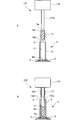
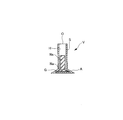
- FIG. 1 It is a block diagram showing the schematic structure of the principal part of main embodiment of the manufacturing apparatus of the metal sodium enclosure engine valve which concerns on this invention. It is a schematic structure figure of a hollow valve. It is a schematic block diagram of the principal part of the getter material addition apparatus of the manufacturing apparatus of FIG. It is a schematic block diagram of the principal part of the metal sodium shaping
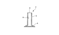
- the hollow valve for sealing metal sodium has a hollow portion H inside the stem portion S and the umbrella portion A and an opening O at the upper end of the stem portion S.
- the opening O is sealed to manufacture a metal sodium-enclosed engine valve in which metal sodium Na is sealed. be able to.
- the manufacturing apparatus inserts a metallic sodium Na for an umbrella part into which a rod-shaped metal sodium Na is inserted into a hollow part H of a hollow valve V.
- Umbrella metal sodium insertion device 130 as a means, and hollow rod H inserted with metal sodium Na by the umbrella metal sodium insertion device 130 into the hollow portion H of the hollow valve V through the opening O, the hollow portion H A melting device 140 that is a melting means for melting the metallic sodium Na in the hollow portion H by heating the umbrella portion A to a temperature at which the metallic sodium Na is melted while pressing the rod-shaped metallic sodium Na inside,
- the stem portion S of the hollow valve V in which the metallic sodium Na is melted by the melting device 140 is less than the temperature at which the metallic sodium Na is melted.
- Stem portion cooling device 150 which is a stem portion cooling means for cooling, and metal sodium insertion means for stem portion for inserting rod-shaped metal sodium Na into hollow portion H of hollow valve V cooled by stem portion cooling device 150
- a getter material which includes a metal sodium insertion device 170 for a stem portion and adds a getter material G into the hollow portion H of the hollow valve V before the metal sodium Na is inserted by the metal sodium insertion device 130 for an umbrella.
- a getter material adding device 110 as an adding means is provided.
- the manufacturing apparatus 100 includes an umbrella metal sodium forming apparatus 120 which is a metal sodium forming means for an umbrella part for forming rod-shaped metal sodium Na to be inserted into the hollow valve V by the metal sodium insertion apparatus 130 for the umbrella part;
- the stem portion sodium metal insertion device 160 is a stem portion metal sodium forming device 160 which is a stem portion metal sodium forming means for forming rod-shaped metal sodium Na to be inserted into the hollow valve V by the stem portion metal sodium insertion device 170.
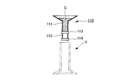
- the getter material adding device 110 has a storage pipe 111 for storing a getter material G made of titanium powder or the like, and a fixed amount whose upper portion is connected to the lower portion of the storage pipe 111 to quantify the getter material G.
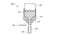
- the metallic sodium forming apparatus 120 for the umbrella part includes an injection cylinder 121 into which block-shaped metallic sodium Na can be put from the base end side, and a pressing piston 122 that can reciprocate inside the injection cylinder 121. And an injection nozzle 123 that is connected to the tip of the injection cylinder 121 and injects the block-shaped metallic sodium Na into a rod shape, and is movably disposed on the tip side of the injection nozzle 123 to quantify the rod-shaped metallic sodium Na.
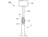
- the umbrella part metallic sodium insertion device 130 moves the metering tube 124 and the shutter 126 while holding the metering tube 124 of the umbrella part metallic sodium forming device 120 detachably.
- a metering tube moving device 131 and an extruding device 132 that reciprocally moves the extruding rod 132a so that the extruding rod 132a can be inserted into and removed from the metering tube 124 are provided.
- the melting device 140 is a high-frequency induction that is a heating unit that places the umbrella part A of the hollow valve V so as to support the hollow valve V and heats the umbrella part A by high-frequency induction heating.
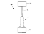
- the pressure rod 142a is moved up and down so that the pressure rod 142a can be inserted into and removed from the inside of the hollow portion H through the opening O of the hollow valve V disposed above the heating device 141 and the high frequency induction heating device 141.
- a metal sodium pressing device 142 which is a metal sodium pressing means.
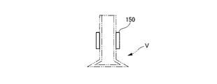
- the stem portion cooling device 150 can detachably hold the stem portion S of the hollow valve V so as to convey and move the hollow valve V, and the coolant flows through the inside.
- the stem portion S can be cooled.
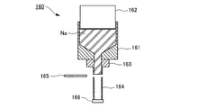
- the stem sodium metal forming device 160 includes an injection cylinder 161 into which block-shaped metal sodium Na is placed from the base end side, and a pressing piston 162 that can reciprocate within the injection cylinder 161. And an injection nozzle 163 that is connected to the tip of the injection cylinder 161 and injects block-shaped metallic sodium Na into a rod shape, and is movably disposed on the tip side of the injection nozzle 163 to quantify the rod-shaped metallic sodium Na.
- a metering tube 164 a cutter 165 disposed so as to move forward and backward between the tip of the injection nozzle 163 and the base end of the metering tube 164, and an openable / closable provided at the tip of the metering tube 164 And a shutter 166.
- the stem sodium metal insertion device 170 detachably holds the metering tube 164 of the stem metal sodium forming device 160 and moves the metering tube 164 and the shutter 166.
- a metering tube moving device 171 and an extruding device 172 that reciprocates the pushing rod 172a so that the pushing rod 172a can be inserted into and removed from the metering tube 164 are provided.
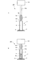
- the hollow valve V When the hollow valve V is disposed at a specified position of the getter material adding device 110 of the manufacturing apparatus 100 and the second shutter 114 is closed and the first shutter 113 is opened as shown in FIG.
- the getter material G in the tube 111 is supplied to the metering tube 112 so as to fill the inside of the metering tube 112.
- the getter material G in the metering tube 112 is added into the hollow portion H from the opening O of the hollow valve V. (Getter material adding step). As a result, a specified amount of getter material G is supplied to the inside of the hollow valve V, and the oxygen concentration in the atmosphere (air) inside the hollow portion H is reduced.
- the hollow valve V to which the getter material G is added by the getter material adding device 110 is transferred to the metallic sodium insertion device 130 for the umbrella portion, and the metallic sodium forming device for the umbrella portion.
- 120 of the metering tubes 124 are held by the metering tube moving device 131 and moved to a specified position of the metallic sodium insertion device 130 for umbrella.
- the extrusion device 132 is operated so as to extrude the metallic sodium Na in the metering tube 124 with the extrusion rod 132a.
- the rod-shaped metallic sodium Na is inserted into the hollow portion H in a specified amount (the metallic sodium inserting step for the umbrella portion).
- the hollow valve V into which the rod-shaped metal sodium Na is inserted in a specified amount by the metallic sodium insertion device 130 for the umbrella is transferred onto the high-frequency induction heating device 141 of the melting device 140.
- the metal sodium pressing device 142 is placed so that the tip of the pressing rod 142a abuts from the opening O on the upper end of the rod-shaped metal sodium Na in the hollow portion H of the hollow valve V. Operate.
- the umbrella portion A of the hollow valve V is brought to a temperature (about 98 ° C. or higher) at which the metallic sodium is melted.
- a temperature about 98 ° C. or higher
- the pressing rod 142a of the metallic sodium pressing device 142 is inserted into the hollow portion H of the hollow valve V to a specified length, the pressing of the metallic sodium Na by the pressing rod 142a is terminated, and the pressing rod 142a
- the metal sodium pressing device 142 is operated so as to be extracted from the hollow portion H of the hollow valve V, and the operation of the high-frequency induction heating device 141 is stopped so as to stop the heating of the umbrella portion A of the hollow valve V ( The melting process).
- the stem portion cooling device 150 holds the stem portion S of the hollow valve V in which the metallic sodium Na is melted by the melting device 140 and inserted into the umbrella portion A.
- the hollow valve V is transferred to the prescribed position of the metallic sodium insertion device 170 for the stem portion while cooling the stem portion S of the hollow valve V below the temperature (about 98 ° C.) for melting the metallic sodium Na. , Stem portion cooling step).
- the cutter 165 is advanced between the distal end of the injection nozzle 163 and the proximal end of the metering tube 164, thereby cutting the metallic sodium Na therebetween, and the metering tube A prescribed amount of metallic sodium Na is molded into a rod shape inside 164 (the metallic sodium molding process for the stem portion).
- the metering tube moving device 171 of the stem metal sodium insertion device 170 holds the metering tube 164 of the stem metal sodium forming device 160 to hold the stem metal sodium.
- the insertion device 170 is moved to a specified position.
- the extrusion device 172 is operated so that the metallic sodium Na in the metering tube 164 is pushed out by the extrusion rod 172a.
- the rod-shaped metallic sodium Na is inserted into the hollow portion H in a specified amount (the metallic sodium insertion step for the stem portion).
- rod-shaped metallic sodium Na is inserted into the hollow portion H of the hollow valve V, and the pressing rod 142a is inserted into the hollow portion H of the hollow valve V from the opening O, so that the hollow portion H
- the umbrella A is heated to a temperature at which the metallic sodium Na is melted while pressing the rod-shaped metallic sodium Na, so that the metallic sodium Na in the hollow portion H is rapidly melted and inserted into the umbrella A part.
- the stem portion S is cooled below the temperature at which the metallic sodium Na is melted, and then inserted into the hollow portion H of the hollow valve V to insert the metallic sodium Na into the stem portion S portion. I tried to put it in.
- the rod-shaped metallic sodium Na is inserted after the getter material G is added into the hollow portion H of the hollow valve V.
- oxygen in the ambient atmosphere Depending on conditions such as concentration and humidity, the addition of the getter material G into the hollow portion H of the hollow valve V can be omitted.
- the manufacturing apparatus 100 including the metal sodium forming apparatuses 120 and 160 for forming rod-shaped metal sodium Na has been described.
- the metal sodium forming apparatuses 120 and 160 are described.
- the umbrella portion A of the hollow valve V is heated by the high frequency induction heating device 141.
- the umbrella portion A of the hollow valve V is heated by an electric heater or the like. It is also possible to do so.
- the umbrella part A of the hollow valve V is heated by the high frequency induction heating device 141, the umbrella part A can be rapidly heated and easily raised to the target temperature in a short time. In this case, it is very suitable.
- the stem portion S of the hollow valve V can be detachably gripped, the hollow valve V can be conveyed and moved, and the hollow portion V can be transferred by the stem portion cooling device 150 that circulates the coolant inside.
- the stem portion cooling device 150 for example, by transporting the hollow valve V by a conveyor or the like, the stem portion S of the hollow valve V is allowed to cool or air is sprayed thereon. It is also possible to cool by air.
- the stem portion cooling device 150 as in the above-described embodiment is applied, the stem portion S of the hollow valve V can be quickly cooled, which is very suitable for continuous production.
- the method and apparatus for manufacturing a metal sodium-enclosed engine valve according to the present invention can be efficiently and continuously produced as a metal sodium-enclosed engine valve while facilitating temperature control, and can be used extremely beneficially industrially. .
Landscapes
- Engineering & Computer Science (AREA)
- Mechanical Engineering (AREA)
- General Engineering & Computer Science (AREA)
- Physics & Mathematics (AREA)
- Electromagnetism (AREA)
- Manufacture Of Electron Tubes, Discharge Lamp Vessels, Lead-In Wires, And The Like (AREA)
- Pressure Welding/Diffusion-Bonding (AREA)
Abstract
中空バルブ(V)の中空部(H)内に棒状の金属ナトリウム(Na)を挿入する傘部用金属ナトリウム挿入装置(130)と、前記装置(130)で金属ナトリウム(Na)を挿入された中空バルブ(V)の中空部(H)内に開口(O)から押圧ロッド(142a)を差し込んで中空部(H)内の棒状の金属ナトリウム(Na)を押圧しながら、金属ナトリウム(Na)を溶融させる温度に傘部(A)を加熱することにより、中空部(H)内の金属ナトリウム(Na)を溶融させる溶融装置(140)と、溶融装置(140)で金属ナトリウム(Na)を溶融された中空バルブ(V)のステム部(S)を、金属ナトリウム(Na)を溶融させる温度未満に冷却するステム部冷却装置(150)と、前記装置(150)で冷却された中空部(H)内に棒状の金属ナトリウム(Na)を挿入するステム部用金属ナトリウム挿入装置(170)とを備える。
Description
本発明は、内部に金属ナトリウムを封入したエンジンバルブを製造する方法及びその装置に関する。
自動車等のエンジンバルブにおいては、エンジンの高性能化や低燃費化等に対応するため、エンジンバルブの内部に中空部を設けて金属ナトリウムを封入することにより、軽量化及び高熱伝達化を図ることが行われている。
このようなエンジンバルブは、例えば、下記特許文献1に記載されているように、金属ナトリウムを溶融させる温度で傘部を保持しつつ、ワイヤ状の金属ナトリウムをステム部の上端の開口から中空部内に繰り入れることにより、金属ナトリウムを中空部内で液化させながら供給して製造することが提案されている。
また、例えば、下記特許文献2に記載されているように、ステム部の上端の開口から傘部の中空部までノズルを挿入して、溶融した金属ナトリウムを当該ノズルから供給することにより、金属ナトリウムを中空部内に注入して製造することが提案されている。
しかしながら、前記特許文献1に記載されている製造方法では、傘部の加熱に伴ってステム部も加熱されてしまうと、ワイヤ状の金属ナトリウムがステム部の中空部内で溶融して、表面張力によりそのままステム部の中空部内に滞留してしまい、傘部の中空部内に金属ナトリウムを供給しにくくなってしまうことから、金属ナトリウムの挿入中、ステム部を金属ナトリウムの融点よりも低い温度で常に保持しなければならず、温度管理に手間がかかってしまう。
また、前記特許文献2に記載されている製造方法では、直径の小さいステム部に対応してノズルの直径を小さくしたとき、溶融した金属ナトリウムの中空部内への注入を何回か繰り返すと、金属ナトリウムがノズルの先端で目詰まりを起こし易く、比較的頻繁にノズルを洗浄しなければならず、連続生産するのに手間がかかってしまう。
そこで、本発明は、温度管理を容易にしながら効率よく連続生産することができる金属ナトリウム封入エンジンバルブの製造方法及びその装置を提供することを目的とする。
前述した課題を解決するための、第一番目の発明に係る金属ナトリウム封入エンジンバルブの製造方法は、ステム部及び傘部の内側に中空部を有すると共に当該ステム部の上端に開口を有する中空バルブの当該ステム部の当該開口から当該中空部内に金属ナトリウムを入れた後、当該開口を封止することにより、内部に金属ナトリウムを封入した金属ナトリウム封入エンジンバルブの製造方法であって、前記中空バルブの前記中空部内に棒状の金属ナトリウムを挿入する傘部用金属ナトリウム挿入工程と、前記傘部用金属ナトリウム挿入工程で金属ナトリウムを挿入された前記中空バルブの前記中空部内に前記開口から押圧ロッドを差し込んで当該中空部内の棒状の金属ナトリウムを押圧しながら、金属ナトリウムを溶融させる温度に前記傘部を加熱することにより、当該中空部内の金属ナトリウムを溶融させる溶融工程と、前記溶融工程で金属ナトリウムを溶融された前記中空バルブの前記ステム部を、金属ナトリウムを溶融させる温度未満に冷却するステム部冷却工程と、前記ステム部冷却工程で冷却された前記中空バルブの前記中空部内に棒状の金属ナトリウムを挿入するステム部用金属ナトリウム挿入工程とを行うことを特徴とする。
また、第二番目の発明に係る金属ナトリウム封入エンジンバルブの製造方法は、第一番目の発明において、前記傘部用金属ナトリウム挿入工程で金属ナトリウムを挿入される前の前記中空バルブの前記中空部内にゲッタ材を添加するゲッタ材添加工程を行うことを特徴とする。
また、第三番目の発明に係る金属ナトリウム封入エンジンバルブの製造方法は、第一番目又は第二番目の発明において、前記溶融工程が、前記中空バルブの前記傘部を高周波誘導加熱によって加熱することを特徴とする。
他方、前述した課題を解決するための、第四番目の発明に係る金属ナトリウム封入エンジンバルブの製造装置は、ステム部及び傘部の内側に中空部を有すると共に当該ステム部の上端に開口を有する中空バルブの当該ステム部の当該開口から当該中空部内に金属ナトリウムを入れた後、当該開口を封止することにより、内部に金属ナトリウムを封入した金属ナトリウム封入エンジンバルブの製造装置であって、前記中空バルブの前記中空部内に棒状の金属ナトリウムを挿入する傘部用金属ナトリウム挿入手段と、前記傘部用金属ナトリウム挿入手段で金属ナトリウムを挿入された前記中空バルブの前記中空部内に前記開口から押圧ロッドを差し込んで当該中空部内の棒状の金属ナトリウムを押圧しながら、金属ナトリウムを溶融させる温度に前記傘部を加熱することにより、当該中空部内の金属ナトリウムを溶融させる溶融手段と、前記溶融手段で金属ナトリウムを溶融された前記中空バルブの前記ステム部を、金属ナトリウムを溶融させる温度未満に冷却するステム部冷却手段と、前記ステム部冷却手段で冷却された前記中空バルブの前記中空部内に棒状の金属ナトリウムを挿入するステム部用金属ナトリウム挿入手段とを備えていることを特徴とする。
また、第五番目の発明に係る金属ナトリウム封入エンジンバルブの製造装置は、第四番目の発明において、前記傘部用金属ナトリウム挿入手段で金属ナトリウムを挿入される前の前記中空バルブの前記中空部内にゲッタ材を添加するゲッタ材添加手段を備えていることを特徴とする。
また、第六番目の発明に係る金属ナトリウム封入エンジンバルブの製造装置は、第四番目又は第五番目の発明において、前記溶融手段が、前記中空バルブを支持するように当該中空バルブの前記傘部を載せられて当該傘部を加熱する加熱手段と、前記加熱手段の上方に配設されて前記中空バルブの前記開口を介して前記中空部内に対して前記押圧ロッドを挿抜できるように当該押圧ロッドを昇降移動させる金属ナトリウム押圧手段とを備えていることを特徴とする。
また、第七番目の発明に係る金属ナトリウム封入エンジンバルブの製造装置は、第六番目の発明において、前記加熱手段が、高周波誘導加熱装置であることを特徴とする。
本発明に係る金属ナトリウム封入エンジンバルブの製造方法及びその装置によれば、中空バルブの中空部内に棒状の金属ナトリウムを挿入して、中空バルブ中空部内に開口から押圧ロッドを差し込んで中空部内の棒状の金属ナトリウムを押圧しながら、金属ナトリウムを溶融させる温度に傘部を加熱することにより、中空部内の金属ナトリウムを迅速に溶融させて傘部部分に入れ込んだ後に、金属ナトリウムを溶融させる温度未満にステム部を冷却してから、中空バルブの中空部内に棒状の金属ナトリウムを挿入することにより、ステム部部分に金属ナトリウムを入れ込むようにしたことから、溶融させた金属ナトリウムを中空バルブの開口から中空部内に供給する必要がないのはもちろんのこと、中空バルブの傘部の加熱に伴ってステム部が高温に加熱されてしまう前に、中空部内の傘部部分に目的とする量の金属ナトリウムNaを迅速に入れ込むことができるので、温度管理を容易にしながら金属ナトリウム封入エンジンバルブを効率よく連続生産することができる。
本発明に係る金属ナトリウム封入エンジンバルブの製造方法及びその装置の実施形態を図面に基づいて説明するが、本発明は図面に基づいて説明する実施形態のみに限定されるものではない。
〈主な実施形態〉
本発明に係る金属ナトリウム封入エンジンバルブの製造方法及びその装置の主な実施形態を図1~17に基づいて説明する。
本発明に係る金属ナトリウム封入エンジンバルブの製造方法及びその装置の主な実施形態を図1~17に基づいて説明する。
まず、金属ナトリウムを封入する中空バルブは、図2に示すように、ステム部S及び傘部Aの内側に中空部Hを有すると共にステム部Sの上端に開口Oを有するものである。この中空バルブVのステム部Sの開口Oから中空部H内に金属ナトリウムNaを入れた後、開口Oを封止することにより、内部に金属ナトリウムNaを封入した金属ナトリウム封入エンジンバルブを製造することができる。
このような金属ナトリウム封入エンジンバルブを製造する本実施形態に係る製造装置は、図1に示すように、中空バルブVの中空部H内に棒状の金属ナトリウムNaを挿入する傘部用金属ナトリウム挿入手段である傘部用金属ナトリウム挿入装置130と、前記傘部用金属ナトリウム挿入装置130で金属ナトリウムNaを挿入された中空バルブVの中空部H内に開口Oから押圧ロッドを差し込んで中空部H内の棒状の金属ナトリウムNaを押圧しながら、金属ナトリウムNaを溶融させる温度に傘部Aを加熱することにより、中空部H内の金属ナトリウムNaを溶融させる溶融手段である溶融装置140と、前記溶融装置140で金属ナトリウムNaを溶融された中空バルブVのステム部Sを、金属ナトリウムNaを溶融させる温度未満に冷却するステム部冷却手段であるステム部冷却装置150と、前記ステム部冷却装置150で冷却された中空バルブVの中空部H内に棒状の金属ナトリウムNaを挿入するステム部用金属ナトリウム挿入手段であるステム部用金属ナトリウム挿入装置170とを備えると共に、前記傘部用金属ナトリウム挿入装置130で金属ナトリウムNaを挿入される前の中空バルブVの中空部H内にゲッタ材Gを添加するゲッタ材添加手段であるゲッタ材添加装置110とを備えている。
さらに、上記製造装置100は、前記傘部用金属ナトリウム挿入装置130で中空バルブVに挿入する棒状の金属ナトリウムNaを成形する傘部用金属ナトリウム成形手段である傘部用金属ナトリウム成形装置120と、前記ステム部用金属ナトリウム挿入装置170で中空バルブVに挿入する棒状の金属ナトリウムNaを成形するステム部用金属ナトリウム成形手段であるステム部用金属ナトリウム成形装置160とを備えている。
前記ゲッタ材添加装置110は、図3に示すように、チタン粉末等からなるゲッタ材Gを貯留する貯留管111と、前記貯留管111の下部に上部を連結されてゲッタ材Gを定量する定量管112と、前記貯留管111と前記定量管112との間を仕切るように設けられた開閉可能な第一シャッタ113と、前記定量管112の下部に設けられた開閉可能な第二シャッタ114とを備えている。
前記傘部用金属ナトリウム成形装置120は、図4に示すように、ブロック形の金属ナトリウムNaを基端側から入れられる射出シリンダ121と、前記射出シリンダ121の内部を往復移動可能な押圧ピストン122と、前記射出シリンダ121の先端に連結されてブロック形の金属ナトリウムNaを棒状に射出する射出ノズル123と、前記射出ノズル123の先端側に移動可能に配設されて棒状の金属ナトリウムNaを定量する定量管124と、前記射出ノズル123の先端と前記定量管124の基端との間で進退移動できるように配設されたカッタ125と、前記定量管124の先端に設けられた開閉可能なシャッタ126とを備えている。
前記傘部用金属ナトリウム挿入装置130は、図5に示すように、前記傘部用金属ナトリウム成形装置120の前記定量管124を着脱可能に保持して当該定量管124及び前記シャッタ126を移動させる定量管移動装置131と、前記定量管124内に対して押出ロッド132aを挿抜できるように当該押出ロッド132aを往復移動させる押出装置132とを備えている。
前記溶融装置140は、図6に示すように、中空バルブVを支持するように当該中空バルブVの傘部Aを載せられて当該傘部Aを高周波誘導加熱によって加熱する加熱手段である高周波誘導加熱装置141と、前記高周波誘導加熱装置141の上方に配設されて中空バルブVの開口Oを介して中空部H内に対して押圧ロッド142aを挿抜できるように当該押圧ロッド142aを昇降移動させる金属ナトリウム押圧手段である金属ナトリウム押圧装置142とを備えている。
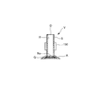
前記ステム部冷却装置150は、図7に示すように、中空バルブVのステム部Sを着脱可能に把持して当該中空バルブVを搬送移動させることができると共に内部に冷却液が流通して当該ステム部Sを冷却することができるようになっている。
前記ステム部用金属ナトリウム成形装置160は、図8に示すように、ブロック形の金属ナトリウムNaを基端側から入れられる射出シリンダ161と、前記射出シリンダ161の内部を往復移動可能な押圧ピストン162と、前記射出シリンダ161の先端に連結されてブロック形の金属ナトリウムNaを棒状に射出する射出ノズル163と、前記射出ノズル163の先端側に移動可能に配設されて棒状の金属ナトリウムNaを定量する定量管164と、前記射出ノズル163の先端と前記定量管164の基端との間で進退移動できるように配設されたカッタ165と、前記定量管164の先端に設けられた開閉可能なシャッタ166とを備えている。
前記ステム部用金属ナトリウム挿入装置170は、図9に示すように、前記ステム部用金属ナトリウム成形装置160の前記定量管164を着脱可能に保持して当該定量管164及び前記シャッタ166を移動させる定量管移動装置171と、前記定量管164内に対して押出ロッド172aを挿抜できるように当該押出ロッド172aを往復移動させる押出装置172とを備えている。
このような本実施形態に係る上記製造装置100を使用する金属ナトリウム封入エンジンバルブの製造方法を次に説明する。
前記中空バルブVを前記製造装置100の前記ゲッタ材添加装置110の規定位置に配設し、図10Aに示すように、前記第二シャッタ114を閉じると共に前記第一シャッタ113を開けると、前記貯留管111内のゲッタ材Gが前記定量管112の内部を満たすように当該定量管112に供給される。
続いて、図10Bに示すように、前記第一シャッタ113を閉じて前記第二シャッタ114を開けると、前記定量管112内のゲッタ材Gが中空バルブVの開口Oから中空部H内に添加される(以上、ゲッタ材添加工程)。これにより、中空バルブVの内部にゲッタ材Gが規定量供給され、中空部H内部の雰囲気(空気)中の酸素濃度が低減される。
また、図11Aに示すように、前記傘部用金属ナトリウム成形装置120の前記射出シリンダ121内のブロック形の金属ナトリウムNaを前記押圧ピストン122で押圧すると、上記金属ナトリウムNaが前記射出ノズル123から棒状となって押し出されて前記定量管124内に供給される。
続いて、図11Bに示すように、前記射出ノズル123の先端と前記定量管124の基端との間に前記カッタ125を進出させることにより、当該間の金属ナトリウムNaを切断し、上記定量管124の内部に規定量の金属ナトリウムNaを棒状に成形する(以上、傘部用金属ナトリウム成形工程)。
そして、図12Aに示すように、前記ゲッタ材添加装置110でゲッタ材Gを添加された中空バルブVを前記傘部用金属ナトリウム挿入装置130に移載すると共に、前記傘部用金属ナトリウム成形装置120の前記定量管124を前記定量管移動装置131で保持して上記傘部用金属ナトリウム挿入装置130の規定位置に移動させる。
続いて、図12Bに示すように、前記シャッタ126を開けた後に、前記定量管124内の金属ナトリウムNaを前記押出ロッド132aで押し出すように前記押出装置132を作動させることにより、中空バルブVの中空部H内に棒状の金属ナトリウムNaを規定量で挿入する(以上、傘部用金属ナトリウム挿入工程)。
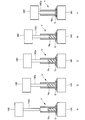
次に、図13Aに示すように、前記傘部用金属ナトリウム挿入装置130で棒状の金属ナトリウムNaを規定量で挿入された中空バルブVを前記溶融装置140の前記高周波誘導加熱装置141上に移載した後、図13Bに示すように、中空バルブVの中空部H内の棒状の金属ナトリウムNaの上端に前記押圧ロッド142aの先端を開口Oから当接させるように前記金属ナトリウム押圧装置142を作動させる。
続いて、図13C~Eに示すように、前記押圧ロッド142aの先端で棒状の金属ナトリウムNaを押圧しながら、金属ナトリウムを溶融させる温度(約98℃以上)に中空バルブVの傘部Aを加熱するように、前記金属ナトリウム押圧装置142及び前記高周波誘導加熱装置141を作動させることにより、中空バルブVの中空部H内の金属ナトリウムNaを溶融させて、傘部A内に入れ込む。
そして、前記金属ナトリウム押圧装置142の前記押圧ロッド142aが中空バルブVの中空部H内に規定長まで挿入されると、当該押圧ロッド142aによる金属ナトリウムNaの押圧を終了して、当該押圧ロッド142aを中空バルブVの中空部H内から引き抜くように当該金属ナトリウム押圧装置142を作動させると共に、中空バルブVの傘部Aの加熱を停止させるように前記高周波誘導加熱装置141の作動を停止させる(以上、溶融工程)。
次に、図14に示すように、前記ステム部冷却装置150が、前記溶融装置140で金属ナトリウムNaを溶融されて傘部A内に入れ込まれた中空バルブVのステム部Sを保持することにより、金属ナトリウムNaを溶融させる温度(約98℃)未満に中空バルブVのステム部Sを冷却しながら、前記ステム部用金属ナトリウム挿入装置170の規定位置に中空バルブVを移載する(以上、ステム部冷却工程)。
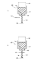
他方、図15Aに示すように、前記ステム部用金属ナトリウム成形装置160の前記射出シリンダ161内のブロック形の金属ナトリウムNaを前記押圧ピストン162で押圧すると、上記金属ナトリウムNaが前記射出ノズル163から棒状となって押し出されて前記定量管164内に供給される。
続いて、図15Bに示すように、前記射出ノズル163の先端と前記定量管164の基端との間に前記カッタ165を進出させることにより、当該間の金属ナトリウムNaを切断し、上記定量管164の内部に規定量の金属ナトリウムNaを棒状に成形する(以上、ステム部用金属ナトリウム成形工程)。
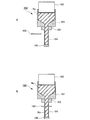
そして、図16Aに示すように、前記ステム部用金属ナトリウム挿入装置170の前記定量管移動装置171で前記ステム部用金属ナトリウム成形装置160の前記定量管164を保持して当該ステム部用金属ナトリウム挿入装置170の規定位置に移動させる。
続いて、図16Bに示すように、前記シャッタ166を開けた後に、前記定量管164内の金属ナトリウムNaを前記押出ロッド172aで押し出すように前記押出装置172を作動させることにより、中空バルブVの中空部H内に棒状の金属ナトリウムNaを規定量で挿入する(以上、ステム部用金属ナトリウム挿入工程)。
これにより、中空バルブVの中空部H内の傘部A部分及びステム部S部分に金属ナトリウムNaが規定量入れ込まれる。その後、中空バルブVの開口Oを封止することにより、金属ナトリウム封入エンジンバルブが製造される。
つまり、本実施形態においては、まず、中空バルブVの中空部H内に棒状の金属ナトリウムNaを挿入して、中空バルブVの中空部H内に開口Oから押圧ロッド142aを差し込んで中空部H内の棒状の金属ナトリウムNaを押圧しながら、金属ナトリウムNaを溶融させる温度に傘部Aを加熱することにより、中空部H内の金属ナトリウムNaを迅速に溶融させて傘部A部分に入れ込んだ後に、金属ナトリウムNaを溶融させる温度未満にステム部Sを冷却してから、中空バルブVの中空部H内に棒状の金属ナトリウムNaを挿入することにより、ステム部S部分に金属ナトリウムNaを入れ込むようにしたのである。
このため、本実施形態では、溶融させた金属ナトリウムNaを中空バルブVの開口Oから中空部H内に供給する必要がないのはもちろんのこと、中空バルブVの傘部Aの加熱に伴ってステム部Sが高温に加熱されてしまう前に、中空部H内の傘部A部分に目的とする量の金属ナトリウムNaを迅速に入れ込むことができる。
したがって、本実施形態によれば、温度管理を容易にしながら金属ナトリウム封入エンジンバルブを効率よく連続生産することができる。
〈他の実施形態〉
なお、前述した実施形態では、中空バルブVの中空部H内にゲッタ材Gを添加してから棒状の金属ナトリウムNaを挿入するようにしたが、他の実施形態として、例えば、周辺雰囲気の酸素濃度や湿度等の条件によっては、中空バルブVの中空部H内へのゲッタ材Gの添加を省略することも可能である。
なお、前述した実施形態では、中空バルブVの中空部H内にゲッタ材Gを添加してから棒状の金属ナトリウムNaを挿入するようにしたが、他の実施形態として、例えば、周辺雰囲気の酸素濃度や湿度等の条件によっては、中空バルブVの中空部H内へのゲッタ材Gの添加を省略することも可能である。
また、前述した実施形態では、棒状の金属ナトリウムNaを成形する金属ナトリウム成形装置120,160を備えた製造装置100の場合について説明したが、他の実施形態として、前記金属ナトリウム成形装置120,160を省略して、例えば、予め成形された棒状の金属ナトリウムNaを容器内に格納しておき、これを金属ナトリウム挿入手段で中空バルブVの中空部H内へ挿入するようにすることも可能である。
また、前述した実施形態では、中空バルブVの傘部Aを高周波誘導加熱装置141で加熱するようにしたが、他の実施形態として、例えば、電熱ヒータ等によって中空バルブVの傘部Aを加熱するようにすることも可能である。しかしながら、高周波誘導加熱装置141によって中空バルブVの傘部Aを加熱するようにすると、傘部Aを急速に加熱して目的とする温度まで短時間で上昇させることが容易にできるので、連続生産に際して非常に好適である。
また、前述した実施形態では、中空バルブVのステム部Sを着脱可能に把持して当該中空バルブVを搬送移動させることができると共に内部に冷却液を流通させるステム部冷却装置150で中空バルブVのステム部Sを冷却するようにしたが、他の実施形態として、例えば、中空バルブVをコンベア等で搬送することにより当該中空バルブVのステム部Sを放冷したり、さらにエアを吹き掛けて空冷するようにすることも可能である。しかしながら、前述した実施形態のようなステム部冷却装置150を適用すると、中空バルブVのステム部Sの冷却を迅速に行うことができるので、連続生産に際して非常に好適である。
本発明に係る金属ナトリウム封入エンジンバルブの製造方法及びその装置は、温度管理を容易にしながら金属ナトリウム封入エンジンバルブを効率よく連続生産することができるので、産業上、極めて有益に利用することができる。
100 製造装置
110 ゲッタ材添加装置
111 貯留管
112 定量管
113 第一シャッタ
114 第二シャッタ
120 傘部用金属ナトリウム成形装置
121 射出シリンダ
122 押圧ピストン
123 射出ノズル
124 定量管
125 カッタ
126 シャッタ
130 傘部用金属ナトリウム挿入装置
131 定量管移動装置
132 押出装置
132a 押出ロッド
140 溶融装置
141 高周波誘導加熱装置
142 金属ナトリウム押圧装置
142a 押圧ロッド
150 ステム部冷却装置
160 ステム部用金属ナトリウム成形装置
161 射出シリンダ
162 押圧ピストン
163 射出ノズル
164 定量管
165 カッタ
166 シャッタ
170 ステム部用金属ナトリウム挿入装置
171 定量管移動装置
172 押出装置
172a 押出ロッド
V 中空バルブ
A 傘部
S ステム部
H 中空部
O 開口
G ゲッタ材
Na 金属ナトリウム
110 ゲッタ材添加装置
111 貯留管
112 定量管
113 第一シャッタ
114 第二シャッタ
120 傘部用金属ナトリウム成形装置
121 射出シリンダ
122 押圧ピストン
123 射出ノズル
124 定量管
125 カッタ
126 シャッタ
130 傘部用金属ナトリウム挿入装置
131 定量管移動装置
132 押出装置
132a 押出ロッド
140 溶融装置
141 高周波誘導加熱装置
142 金属ナトリウム押圧装置
142a 押圧ロッド
150 ステム部冷却装置
160 ステム部用金属ナトリウム成形装置
161 射出シリンダ
162 押圧ピストン
163 射出ノズル
164 定量管
165 カッタ
166 シャッタ
170 ステム部用金属ナトリウム挿入装置
171 定量管移動装置
172 押出装置
172a 押出ロッド
V 中空バルブ
A 傘部
S ステム部
H 中空部
O 開口
G ゲッタ材
Na 金属ナトリウム
Claims (7)
- ステム部及び傘部の内側に中空部を有すると共に当該ステム部の上端に開口を有する中空バルブの当該ステム部の当該開口から当該中空部内に金属ナトリウムを入れた後、当該開口を封止することにより、内部に金属ナトリウムを封入した金属ナトリウム封入エンジンバルブの製造方法であって、
前記中空バルブの前記中空部内に棒状の金属ナトリウムを挿入する傘部用金属ナトリウム挿入工程と、
前記傘部用金属ナトリウム挿入工程で金属ナトリウムを挿入された前記中空バルブの前記中空部内に前記開口から押圧ロッドを差し込んで当該中空部内の棒状の金属ナトリウムを押圧しながら、金属ナトリウムを溶融させる温度に前記傘部を加熱することにより、当該中空部内の金属ナトリウムを溶融させる溶融工程と、
前記溶融工程で金属ナトリウムを溶融された前記中空バルブの前記ステム部を、金属ナトリウムを溶融させる温度未満に冷却するステム部冷却工程と、
前記ステム部冷却工程で冷却された前記中空バルブの前記中空部内に棒状の金属ナトリウムを挿入するステム部用金属ナトリウム挿入工程と
を行うことを特徴とする金属ナトリウム封入エンジンバルブの製造方法。 - 請求項1に記載の金属ナトリウム封入エンジンバルブの製造方法において、
前記傘部用金属ナトリウム挿入工程で金属ナトリウムを挿入される前の前記中空バルブの前記中空部内にゲッタ材を添加するゲッタ材添加工程を行う
ことを特徴とする金属ナトリウム封入エンジンバルブの製造方法。 - 請求項1又は請求項2に記載の金属ナトリウム封入エンジンバルブの製造方法において、
前記溶融工程が、前記中空バルブの前記傘部を高周波誘導加熱によって加熱する
ことを特徴とする金属ナトリウム封入エンジンバルブの製造方法。 - ステム部及び傘部の内側に中空部を有すると共に当該ステム部の上端に開口を有する中空バルブの当該ステム部の当該開口から当該中空部内に金属ナトリウムを入れた後、当該開口を封止することにより、内部に金属ナトリウムを封入した金属ナトリウム封入エンジンバルブの製造装置であって、
前記中空バルブの前記中空部内に棒状の金属ナトリウムを挿入する傘部用金属ナトリウム挿入手段と、
前記傘部用金属ナトリウム挿入手段で金属ナトリウムを挿入された前記中空バルブの前記中空部内に前記開口から押圧ロッドを差し込んで当該中空部内の棒状の金属ナトリウムを押圧しながら、金属ナトリウムを溶融させる温度に前記傘部を加熱することにより、当該中空部内の金属ナトリウムを溶融させる溶融手段と、
前記溶融手段で金属ナトリウムを溶融された前記中空バルブの前記ステム部を、金属ナトリウムを溶融させる温度未満に冷却するステム部冷却手段と、
前記ステム部冷却手段で冷却された前記中空バルブの前記中空部内に棒状の金属ナトリウムを挿入するステム部用金属ナトリウム挿入手段と
を備えていることを特徴とする金属ナトリウム封入エンジンバルブの製造装置。 - 請求項4に記載の金属ナトリウム封入エンジンバルブの製造装置において、
前記傘部用金属ナトリウム挿入手段で金属ナトリウムを挿入される前の前記中空バルブの前記中空部内にゲッタ材を添加するゲッタ材添加手段を備えている
ことを特徴とする金属ナトリウム封入エンジンバルブの製造装置。 - 請求項4又は請求項5に記載の金属ナトリウム封入エンジンバルブの製造装置において、
前記溶融手段が、
前記中空バルブを支持するように当該中空バルブの前記傘部を載せられて当該傘部を加熱する加熱手段と、
前記加熱手段の上方に配設されて前記中空バルブの前記開口を介して前記中空部内に対して前記押圧ロッドを挿抜できるように当該押圧ロッドを昇降移動させる金属ナトリウム押圧手段と
を備えていることを特徴とする金属ナトリウム封入エンジンバルブの製造装置。 - 請求項6に記載の金属ナトリウム封入エンジンバルブの製造装置において、
前記加熱手段が、高周波誘導加熱装置である
ことを特徴とする金属ナトリウム封入エンジンバルブの製造装置。
Priority Applications (4)
| Application Number | Priority Date | Filing Date | Title |
|---|---|---|---|
| CN201680024164.5A CN107532486A (zh) | 2015-04-28 | 2016-02-26 | 封入金属钠发动机气门的制造方法及其装置 |
| PL16786189T PL3290664T3 (pl) | 2015-04-28 | 2016-02-26 | Sposób i urządzenie do wytwarzania zaworu silnikowego wypełnionego sodem metalicznym |
| EP16786189.7A EP3290664B1 (en) | 2015-04-28 | 2016-02-26 | Method and device for manufacturing metallic-sodium-filled engine valve |
| US15/569,606 US10677110B2 (en) | 2015-04-28 | 2016-02-26 | Method and device for manufacturing metallic-sodium-filled engine valve |
Applications Claiming Priority (2)
| Application Number | Priority Date | Filing Date | Title |
|---|---|---|---|
| JP2015-091109 | 2015-04-28 | ||
| JP2015091109A JP5843991B1 (ja) | 2015-04-28 | 2015-04-28 | 金属ナトリウム封入エンジンバルブの製造方法及びその装置 |
Publications (1)
| Publication Number | Publication Date |
|---|---|
| WO2016174912A1 true WO2016174912A1 (ja) | 2016-11-03 |
Family
ID=55073339
Family Applications (1)
| Application Number | Title | Priority Date | Filing Date |
|---|---|---|---|
| PCT/JP2016/055748 Ceased WO2016174912A1 (ja) | 2015-04-28 | 2016-02-26 | 金属ナトリウム封入エンジンバルブの製造方法及びその装置 |
Country Status (6)
| Country | Link |
|---|---|
| US (1) | US10677110B2 (ja) |
| EP (1) | EP3290664B1 (ja) |
| JP (1) | JP5843991B1 (ja) |
| CN (1) | CN107532486A (ja) |
| PL (1) | PL3290664T3 (ja) |
| WO (1) | WO2016174912A1 (ja) |
Cited By (1)
| Publication number | Priority date | Publication date | Assignee | Title |
|---|---|---|---|---|
| CN115003899A (zh) * | 2020-07-14 | 2022-09-02 | 富士乌兹克斯株式会社 | 伞中空发动机气门的冷却材料填充装置以及冷却材料的填充方法 |
Families Citing this family (2)
| Publication number | Priority date | Publication date | Assignee | Title |
|---|---|---|---|---|
| DE102019132085A1 (de) * | 2019-11-27 | 2021-05-27 | Federal-Mogul Valvetrain Gmbh | Verfahren und Vorrichtung zum Herstellen von hohlen, innengekühlten Ventilen |
| DE102023200287A1 (de) * | 2023-01-16 | 2024-08-01 | Mahle International Gmbh | Ventil für eine Brennkraftmaschine und Herstellungsverfahren |
Citations (5)
| Publication number | Priority date | Publication date | Assignee | Title |
|---|---|---|---|---|
| JP2002224812A (ja) * | 2001-01-29 | 2002-08-13 | Ube Machinery Corporation Ltd | 金属溶解装置及び金属溶解方法 |
| JP2006519952A (ja) * | 2003-02-18 | 2006-08-31 | ハーヨットエス ファールツォイクテクニック ゲーエムベーハー ウント コー カーゲー | 内燃機関の排気系統に組み込まれた還元型触媒コンバータにアンモニアを供給する装置 |
| JP2011236839A (ja) * | 2010-05-12 | 2011-11-24 | Mitsubishi Heavy Ind Ltd | 金属ナトリウム封入エンジンバルブの製造方法 |
| JP2012136979A (ja) * | 2010-12-24 | 2012-07-19 | Mitsubishi Heavy Ind Ltd | 金属ナトリウム含有エンジンバルブの製造方法、金属ナトリウム供給装置 |
| JP2014152636A (ja) * | 2013-02-05 | 2014-08-25 | Mitsubishi Heavy Ind Ltd | バルブの製造方法、及びNa供給装置 |
Family Cites Families (8)
| Publication number | Priority date | Publication date | Assignee | Title |
|---|---|---|---|---|
| US4459949A (en) * | 1982-02-12 | 1984-07-17 | Teves-Thompson Gmbh | Liquid metal cooled internal combustion engine valves with getter |
| JP2711301B2 (ja) | 1990-03-09 | 1998-02-10 | フジオーゼックス株式会社 | 内燃機関用流体冷却弁 |
| JP2832756B2 (ja) * | 1990-12-28 | 1998-12-09 | フジオーゼックス株式会社 | 中空弁への金属ナトリウムの挿入方法及びその装置 |
| JPH07119421A (ja) | 1993-10-25 | 1995-05-09 | Mitsubishi Heavy Ind Ltd | Na封入中空エンジンバルブの製造方法 |
| EP1626797A1 (de) | 2003-05-26 | 2006-02-22 | HJS Fahrzeugtechnik GmbH & Co. KG | VORRRICHTUNG ZUM BEFREIEN EINER EIN AUS EINER ERSTEN PHASE IN EINE ZWEITE PHASE GEBRACHTES EDUKTIONSMITTEL F HRENDEN ZUFÜ ;HRLEITUNG VON IN DIE ERSTE PHASE ZUR CKGEBILDETEM REDUKTION SMITTEL |
| JP4688145B2 (ja) | 2005-06-09 | 2011-05-25 | 日本碍子株式会社 | ダイキャスト装置及びダイキャスト方法 |
| JP4526097B1 (ja) * | 2009-12-24 | 2010-08-18 | 株式会社 吉村カンパニー | 中空エンジンバルブの弁傘部の製造方法及び中空エンジンバルブの弁傘部のプレス装置及び中空エンジンバルブ |
| JP2012136978A (ja) | 2010-12-24 | 2012-07-19 | Mitsubishi Heavy Ind Ltd | 金属ナトリウム供給装置 |
-
2015
- 2015-04-28 JP JP2015091109A patent/JP5843991B1/ja not_active Expired - Fee Related
-
2016
- 2016-02-26 EP EP16786189.7A patent/EP3290664B1/en not_active Not-in-force
- 2016-02-26 PL PL16786189T patent/PL3290664T3/pl unknown
- 2016-02-26 WO PCT/JP2016/055748 patent/WO2016174912A1/ja not_active Ceased
- 2016-02-26 US US15/569,606 patent/US10677110B2/en not_active Expired - Fee Related
- 2016-02-26 CN CN201680024164.5A patent/CN107532486A/zh active Pending
Patent Citations (5)
| Publication number | Priority date | Publication date | Assignee | Title |
|---|---|---|---|---|
| JP2002224812A (ja) * | 2001-01-29 | 2002-08-13 | Ube Machinery Corporation Ltd | 金属溶解装置及び金属溶解方法 |
| JP2006519952A (ja) * | 2003-02-18 | 2006-08-31 | ハーヨットエス ファールツォイクテクニック ゲーエムベーハー ウント コー カーゲー | 内燃機関の排気系統に組み込まれた還元型触媒コンバータにアンモニアを供給する装置 |
| JP2011236839A (ja) * | 2010-05-12 | 2011-11-24 | Mitsubishi Heavy Ind Ltd | 金属ナトリウム封入エンジンバルブの製造方法 |
| JP2012136979A (ja) * | 2010-12-24 | 2012-07-19 | Mitsubishi Heavy Ind Ltd | 金属ナトリウム含有エンジンバルブの製造方法、金属ナトリウム供給装置 |
| JP2014152636A (ja) * | 2013-02-05 | 2014-08-25 | Mitsubishi Heavy Ind Ltd | バルブの製造方法、及びNa供給装置 |
Cited By (2)
| Publication number | Priority date | Publication date | Assignee | Title |
|---|---|---|---|---|
| CN115003899A (zh) * | 2020-07-14 | 2022-09-02 | 富士乌兹克斯株式会社 | 伞中空发动机气门的冷却材料填充装置以及冷却材料的填充方法 |
| CN115003899B (zh) * | 2020-07-14 | 2024-03-08 | 富士乌兹克斯株式会社 | 伞中空发动机气门的冷却材料填充装置以及冷却材料的填充方法 |
Also Published As
| Publication number | Publication date |
|---|---|
| US10677110B2 (en) | 2020-06-09 |
| PL3290664T3 (pl) | 2020-09-21 |
| JP5843991B1 (ja) | 2016-01-13 |
| EP3290664A1 (en) | 2018-03-07 |
| EP3290664B1 (en) | 2020-04-22 |
| EP3290664A4 (en) | 2019-01-02 |
| CN107532486A (zh) | 2018-01-02 |
| JP2016205331A (ja) | 2016-12-08 |
| US20180298793A1 (en) | 2018-10-18 |
Similar Documents
| Publication | Publication Date | Title |
|---|---|---|
| JP5843991B1 (ja) | 金属ナトリウム封入エンジンバルブの製造方法及びその装置 | |
| CN106457346B (zh) | 成型装置及成型方法 | |
| CN1876278B (zh) | 压铸机和压铸方法 | |
| CN102762825A (zh) | 金属钠封入发动机气门的制造方法 | |
| CN105648257B (zh) | 一种制备大尺寸碳铜复合材料的连续化热等静压浸渍方法 | |
| US9044883B2 (en) | Method for making containers comprising an intermediate depressuring operation | |
| AU2015280958A1 (en) | Apparatus and method for melting and molding metal in vacuum environment | |
| CN104550822A (zh) | 成形装置、半凝固金属的制造装置、成形方法及制造方法 | |
| CN110508777A (zh) | 一种非晶合金立式压铸机和压铸方法 | |
| JPH0318605A (ja) | 中空エンジンバルブヘの金属ナトリウム注入方法及びその装置 | |
| JP5215667B2 (ja) | 一体的に形成された成型部分およびその作成方法 | |
| EP3167977B1 (en) | Mold apparatus for molding metal in high vacuum environment | |
| CN101834103B (zh) | 一种双螺旋节能荧光灯管的加工方法 | |
| US7244388B2 (en) | Process for producing hollow bodies of thermoplastic material and apparatus for same | |
| CN105567991A (zh) | 熔炼设备 | |
| US20150202684A1 (en) | Method for molding amorphous alloy, and molded object prouduced by said molding method | |
| CN208601937U (zh) | 胶管熔接装置 | |
| CN107225374B (zh) | 一种薄壁注塑模芯的制造方法 | |
| JP2011236839A (ja) | 金属ナトリウム封入エンジンバルブの製造方法 | |
| KR20180094519A (ko) | 폴리케톤 바 제작방법 | |
| EP3646966B1 (en) | Injection unit for diecasting machines and method | |
| CN118181666B (zh) | 一种高分子焊丝盘注塑成型装置及其成型工艺 | |
| CN108115140A (zh) | 生产热变形磁体的方法和设备 | |
| CN206230863U (zh) | 一种3d、2d吹塑加工模具 | |
| JP4290497B2 (ja) | 還元鋳造方法および還元鋳造装置 |
Legal Events
| Date | Code | Title | Description |
|---|---|---|---|
| 121 | Ep: the epo has been informed by wipo that ep was designated in this application |
Ref document number: 16786189 Country of ref document: EP Kind code of ref document: A1 |
|
| WWE | Wipo information: entry into national phase |
Ref document number: 15569606 Country of ref document: US |
|
| NENP | Non-entry into the national phase |
Ref country code: DE |