WO2016174936A1 - 燃料タンク - Google Patents
燃料タンク Download PDFInfo
- Publication number
- WO2016174936A1 WO2016174936A1 PCT/JP2016/057308 JP2016057308W WO2016174936A1 WO 2016174936 A1 WO2016174936 A1 WO 2016174936A1 JP 2016057308 W JP2016057308 W JP 2016057308W WO 2016174936 A1 WO2016174936 A1 WO 2016174936A1
- Authority
- WO
- WIPO (PCT)
- Prior art keywords
- fuel tank
- tank body
- base
- extending
- protrusion
- Prior art date
- Legal status (The legal status is an assumption and is not a legal conclusion. Google has not performed a legal analysis and makes no representation as to the accuracy of the status listed.)
- Ceased
Links
Images


Classifications
-
- B—PERFORMING OPERATIONS; TRANSPORTING
- B60—VEHICLES IN GENERAL
- B60K—ARRANGEMENT OR MOUNTING OF PROPULSION UNITS OR OF TRANSMISSIONS IN VEHICLES; ARRANGEMENT OR MOUNTING OF PLURAL DIVERSE PRIME-MOVERS IN VEHICLES; AUXILIARY DRIVES FOR VEHICLES; INSTRUMENTATION OR DASHBOARDS FOR VEHICLES; ARRANGEMENTS IN CONNECTION WITH COOLING, AIR INTAKE, GAS EXHAUST OR FUEL SUPPLY OF PROPULSION UNITS IN VEHICLES
- B60K15/00—Arrangement in connection with fuel supply of combustion engines or other fuel consuming energy converters, e.g. fuel cells; Mounting or construction of fuel tanks
- B60K15/03—Fuel tanks
-
- B—PERFORMING OPERATIONS; TRANSPORTING
- B29—WORKING OF PLASTICS; WORKING OF SUBSTANCES IN A PLASTIC STATE IN GENERAL
- B29C—SHAPING OR JOINING OF PLASTICS; SHAPING OF MATERIAL IN A PLASTIC STATE, NOT OTHERWISE PROVIDED FOR; AFTER-TREATMENT OF THE SHAPED PRODUCTS, e.g. REPAIRING
- B29C48/00—Extrusion moulding, i.e. expressing the moulding material through a die or nozzle which imparts the desired form; Apparatus therefor
- B29C48/022—Extrusion moulding, i.e. expressing the moulding material through a die or nozzle which imparts the desired form; Apparatus therefor characterised by the choice of material
-
- B—PERFORMING OPERATIONS; TRANSPORTING
- B29—WORKING OF PLASTICS; WORKING OF SUBSTANCES IN A PLASTIC STATE IN GENERAL
- B29C—SHAPING OR JOINING OF PLASTICS; SHAPING OF MATERIAL IN A PLASTIC STATE, NOT OTHERWISE PROVIDED FOR; AFTER-TREATMENT OF THE SHAPED PRODUCTS, e.g. REPAIRING
- B29C49/00—Blow-moulding, i.e. blowing a preform or parison to a desired shape within a mould; Apparatus therefor
- B29C49/20—Blow-moulding, i.e. blowing a preform or parison to a desired shape within a mould; Apparatus therefor of articles having inserts or reinforcements ; Handling of inserts or reinforcements
-
- B—PERFORMING OPERATIONS; TRANSPORTING
- B29—WORKING OF PLASTICS; WORKING OF SUBSTANCES IN A PLASTIC STATE IN GENERAL
- B29C—SHAPING OR JOINING OF PLASTICS; SHAPING OF MATERIAL IN A PLASTIC STATE, NOT OTHERWISE PROVIDED FOR; AFTER-TREATMENT OF THE SHAPED PRODUCTS, e.g. REPAIRING
- B29C49/00—Blow-moulding, i.e. blowing a preform or parison to a desired shape within a mould; Apparatus therefor
- B29C49/42—Component parts, details or accessories; Auxiliary operations
- B29C49/48—Moulds
-
- B—PERFORMING OPERATIONS; TRANSPORTING
- B29—WORKING OF PLASTICS; WORKING OF SUBSTANCES IN A PLASTIC STATE IN GENERAL
- B29C—SHAPING OR JOINING OF PLASTICS; SHAPING OF MATERIAL IN A PLASTIC STATE, NOT OTHERWISE PROVIDED FOR; AFTER-TREATMENT OF THE SHAPED PRODUCTS, e.g. REPAIRING
- B29C51/00—Shaping by thermoforming, i.e. shaping sheets or sheet like preforms after heating, e.g. shaping sheets in matched moulds or by deep-drawing; Apparatus therefor
- B29C51/02—Combined thermoforming and manufacture of the preform
-
- B—PERFORMING OPERATIONS; TRANSPORTING
- B29—WORKING OF PLASTICS; WORKING OF SUBSTANCES IN A PLASTIC STATE IN GENERAL
- B29C—SHAPING OR JOINING OF PLASTICS; SHAPING OF MATERIAL IN A PLASTIC STATE, NOT OTHERWISE PROVIDED FOR; AFTER-TREATMENT OF THE SHAPED PRODUCTS, e.g. REPAIRING
- B29C51/00—Shaping by thermoforming, i.e. shaping sheets or sheet like preforms after heating, e.g. shaping sheets in matched moulds or by deep-drawing; Apparatus therefor
- B29C51/12—Shaping by thermoforming, i.e. shaping sheets or sheet like preforms after heating, e.g. shaping sheets in matched moulds or by deep-drawing; Apparatus therefor of articles having inserts or reinforcements
-
- B—PERFORMING OPERATIONS; TRANSPORTING
- B29—WORKING OF PLASTICS; WORKING OF SUBSTANCES IN A PLASTIC STATE IN GENERAL
- B29C—SHAPING OR JOINING OF PLASTICS; SHAPING OF MATERIAL IN A PLASTIC STATE, NOT OTHERWISE PROVIDED FOR; AFTER-TREATMENT OF THE SHAPED PRODUCTS, e.g. REPAIRING
- B29C51/00—Shaping by thermoforming, i.e. shaping sheets or sheet like preforms after heating, e.g. shaping sheets in matched moulds or by deep-drawing; Apparatus therefor
- B29C51/26—Component parts, details or accessories; Auxiliary operations
- B29C51/30—Moulds
-
- F—MECHANICAL ENGINEERING; LIGHTING; HEATING; WEAPONS; BLASTING
- F02—COMBUSTION ENGINES; HOT-GAS OR COMBUSTION-PRODUCT ENGINE PLANTS
- F02M—SUPPLYING COMBUSTION ENGINES IN GENERAL WITH COMBUSTIBLE MIXTURES OR CONSTITUENTS THEREOF
- F02M37/00—Apparatus or systems for feeding liquid fuel from storage containers to carburettors or fuel-injection apparatus; Arrangements for purifying liquid fuel specially adapted for, or arranged on, internal-combustion engines
-
- B—PERFORMING OPERATIONS; TRANSPORTING
- B29—WORKING OF PLASTICS; WORKING OF SUBSTANCES IN A PLASTIC STATE IN GENERAL
- B29C—SHAPING OR JOINING OF PLASTICS; SHAPING OF MATERIAL IN A PLASTIC STATE, NOT OTHERWISE PROVIDED FOR; AFTER-TREATMENT OF THE SHAPED PRODUCTS, e.g. REPAIRING
- B29C49/00—Blow-moulding, i.e. blowing a preform or parison to a desired shape within a mould; Apparatus therefor
- B29C49/20—Blow-moulding, i.e. blowing a preform or parison to a desired shape within a mould; Apparatus therefor of articles having inserts or reinforcements ; Handling of inserts or reinforcements
- B29C2049/2008—Blow-moulding, i.e. blowing a preform or parison to a desired shape within a mould; Apparatus therefor of articles having inserts or reinforcements ; Handling of inserts or reinforcements inside the article
- B29C2049/2013—Blow-moulding, i.e. blowing a preform or parison to a desired shape within a mould; Apparatus therefor of articles having inserts or reinforcements ; Handling of inserts or reinforcements inside the article for connecting opposite walls, e.g. baffles in a fuel tank
-
- B—PERFORMING OPERATIONS; TRANSPORTING
- B29—WORKING OF PLASTICS; WORKING OF SUBSTANCES IN A PLASTIC STATE IN GENERAL
- B29C—SHAPING OR JOINING OF PLASTICS; SHAPING OF MATERIAL IN A PLASTIC STATE, NOT OTHERWISE PROVIDED FOR; AFTER-TREATMENT OF THE SHAPED PRODUCTS, e.g. REPAIRING
- B29C2948/00—Indexing scheme relating to extrusion moulding
- B29C2948/92—Measuring, controlling or regulating
- B29C2948/92504—Controlled parameter
- B29C2948/92704—Temperature
-
- B—PERFORMING OPERATIONS; TRANSPORTING
- B29—WORKING OF PLASTICS; WORKING OF SUBSTANCES IN A PLASTIC STATE IN GENERAL
- B29C—SHAPING OR JOINING OF PLASTICS; SHAPING OF MATERIAL IN A PLASTIC STATE, NOT OTHERWISE PROVIDED FOR; AFTER-TREATMENT OF THE SHAPED PRODUCTS, e.g. REPAIRING
- B29C2948/00—Indexing scheme relating to extrusion moulding
- B29C2948/92—Measuring, controlling or regulating
- B29C2948/92819—Location or phase of control
- B29C2948/92828—Raw material handling or dosing, e.g. active hopper or feeding device
-
- B—PERFORMING OPERATIONS; TRANSPORTING
- B29—WORKING OF PLASTICS; WORKING OF SUBSTANCES IN A PLASTIC STATE IN GENERAL
- B29C—SHAPING OR JOINING OF PLASTICS; SHAPING OF MATERIAL IN A PLASTIC STATE, NOT OTHERWISE PROVIDED FOR; AFTER-TREATMENT OF THE SHAPED PRODUCTS, e.g. REPAIRING
- B29C48/00—Extrusion moulding, i.e. expressing the moulding material through a die or nozzle which imparts the desired form; Apparatus therefor
- B29C48/03—Extrusion moulding, i.e. expressing the moulding material through a die or nozzle which imparts the desired form; Apparatus therefor characterised by the shape of the extruded material at extrusion
-
- B—PERFORMING OPERATIONS; TRANSPORTING
- B29—WORKING OF PLASTICS; WORKING OF SUBSTANCES IN A PLASTIC STATE IN GENERAL
- B29C—SHAPING OR JOINING OF PLASTICS; SHAPING OF MATERIAL IN A PLASTIC STATE, NOT OTHERWISE PROVIDED FOR; AFTER-TREATMENT OF THE SHAPED PRODUCTS, e.g. REPAIRING
- B29C48/00—Extrusion moulding, i.e. expressing the moulding material through a die or nozzle which imparts the desired form; Apparatus therefor
- B29C48/25—Component parts, details or accessories; Auxiliary operations
- B29C48/285—Feeding the extrusion material to the extruder
- B29C48/29—Feeding the extrusion material to the extruder in liquid form
-
- B—PERFORMING OPERATIONS; TRANSPORTING
- B29—WORKING OF PLASTICS; WORKING OF SUBSTANCES IN A PLASTIC STATE IN GENERAL
- B29K—INDEXING SCHEME ASSOCIATED WITH SUBCLASSES B29B, B29C OR B29D, RELATING TO MOULDING MATERIALS OR TO MATERIALS FOR MOULDS, REINFORCEMENTS, FILLERS OR PREFORMED PARTS, e.g. INSERTS
- B29K2075/00—Use of PU, i.e. polyureas or polyurethanes or derivatives thereof, as moulding material
-
- B—PERFORMING OPERATIONS; TRANSPORTING
- B29—WORKING OF PLASTICS; WORKING OF SUBSTANCES IN A PLASTIC STATE IN GENERAL
- B29K—INDEXING SCHEME ASSOCIATED WITH SUBCLASSES B29B, B29C OR B29D, RELATING TO MOULDING MATERIALS OR TO MATERIALS FOR MOULDS, REINFORCEMENTS, FILLERS OR PREFORMED PARTS, e.g. INSERTS
- B29K2083/00—Use of polymers having silicon, with or without sulfur, nitrogen, oxygen, or carbon only, in the main chain, as moulding material
- B29K2083/005—LSR, i.e. liquid silicone rubbers, or derivatives thereof
-
- B—PERFORMING OPERATIONS; TRANSPORTING
- B29—WORKING OF PLASTICS; WORKING OF SUBSTANCES IN A PLASTIC STATE IN GENERAL
- B29K—INDEXING SCHEME ASSOCIATED WITH SUBCLASSES B29B, B29C OR B29D, RELATING TO MOULDING MATERIALS OR TO MATERIALS FOR MOULDS, REINFORCEMENTS, FILLERS OR PREFORMED PARTS, e.g. INSERTS
- B29K2105/00—Condition, form or state of moulded material or of the material to be shaped
- B29K2105/0094—Condition, form or state of moulded material or of the material to be shaped having particular viscosity
-
- B—PERFORMING OPERATIONS; TRANSPORTING
- B29—WORKING OF PLASTICS; WORKING OF SUBSTANCES IN A PLASTIC STATE IN GENERAL
- B29K—INDEXING SCHEME ASSOCIATED WITH SUBCLASSES B29B, B29C OR B29D, RELATING TO MOULDING MATERIALS OR TO MATERIALS FOR MOULDS, REINFORCEMENTS, FILLERS OR PREFORMED PARTS, e.g. INSERTS
- B29K2105/00—Condition, form or state of moulded material or of the material to be shaped
- B29K2105/24—Condition, form or state of moulded material or of the material to be shaped crosslinked or vulcanised
- B29K2105/243—Partially cured
-
- B—PERFORMING OPERATIONS; TRANSPORTING
- B29—WORKING OF PLASTICS; WORKING OF SUBSTANCES IN A PLASTIC STATE IN GENERAL
- B29L—INDEXING SCHEME ASSOCIATED WITH SUBCLASS B29C, RELATING TO PARTICULAR ARTICLES
- B29L2031/00—Other particular articles
- B29L2031/712—Containers; Packaging elements or accessories, Packages
- B29L2031/7172—Fuel tanks, jerry cans
-
- B—PERFORMING OPERATIONS; TRANSPORTING
- B60—VEHICLES IN GENERAL
- B60K—ARRANGEMENT OR MOUNTING OF PROPULSION UNITS OR OF TRANSMISSIONS IN VEHICLES; ARRANGEMENT OR MOUNTING OF PLURAL DIVERSE PRIME-MOVERS IN VEHICLES; AUXILIARY DRIVES FOR VEHICLES; INSTRUMENTATION OR DASHBOARDS FOR VEHICLES; ARRANGEMENTS IN CONNECTION WITH COOLING, AIR INTAKE, GAS EXHAUST OR FUEL SUPPLY OF PROPULSION UNITS IN VEHICLES
- B60K15/00—Arrangement in connection with fuel supply of combustion engines or other fuel consuming energy converters, e.g. fuel cells; Mounting or construction of fuel tanks
- B60K15/03—Fuel tanks
- B60K15/03177—Fuel tanks made of non-metallic material, e.g. plastics, or of a combination of non-metallic and metallic material
-
- B—PERFORMING OPERATIONS; TRANSPORTING
- B60—VEHICLES IN GENERAL
- B60K—ARRANGEMENT OR MOUNTING OF PROPULSION UNITS OR OF TRANSMISSIONS IN VEHICLES; ARRANGEMENT OR MOUNTING OF PLURAL DIVERSE PRIME-MOVERS IN VEHICLES; AUXILIARY DRIVES FOR VEHICLES; INSTRUMENTATION OR DASHBOARDS FOR VEHICLES; ARRANGEMENTS IN CONNECTION WITH COOLING, AIR INTAKE, GAS EXHAUST OR FUEL SUPPLY OF PROPULSION UNITS IN VEHICLES
- B60K15/00—Arrangement in connection with fuel supply of combustion engines or other fuel consuming energy converters, e.g. fuel cells; Mounting or construction of fuel tanks
- B60K15/03—Fuel tanks
- B60K2015/03032—Manufacturing of fuel tanks
-
- B—PERFORMING OPERATIONS; TRANSPORTING
- B60—VEHICLES IN GENERAL
- B60K—ARRANGEMENT OR MOUNTING OF PROPULSION UNITS OR OF TRANSMISSIONS IN VEHICLES; ARRANGEMENT OR MOUNTING OF PLURAL DIVERSE PRIME-MOVERS IN VEHICLES; AUXILIARY DRIVES FOR VEHICLES; INSTRUMENTATION OR DASHBOARDS FOR VEHICLES; ARRANGEMENTS IN CONNECTION WITH COOLING, AIR INTAKE, GAS EXHAUST OR FUEL SUPPLY OF PROPULSION UNITS IN VEHICLES
- B60K15/00—Arrangement in connection with fuel supply of combustion engines or other fuel consuming energy converters, e.g. fuel cells; Mounting or construction of fuel tanks
- B60K15/03—Fuel tanks
- B60K2015/03486—Fuel tanks characterised by the materials the tank or parts thereof are essentially made from
- B60K2015/03493—Fuel tanks characterised by the materials the tank or parts thereof are essentially made from made of plastics
Definitions
- the present invention relates to a fuel tank.
- Patent Document 1 As a fuel tank mounted on an automobile, one described in Patent Document 1 is known.
- the fuel tank of Patent Document 1 describes a structure in which a frame member is provided on the outer peripheral surface of a resin fuel tank main body. According to this fuel tank, the fuel tank can be reinforced by the frame member.
- the fuel tank undergoes positive pressure deformation or negative pressure deformation due to a change in internal pressure caused by a change in the outside air temperature or a temperature change due to the heat of the exhaust system.
- a resin fuel tank is easily affected by such external factors.
- the positive pressure deformation of the fuel tank body can be suppressed by the frame member, but there is a problem that it cannot cope with the negative pressure deformation.
- the fuel tank main body is deformed by negative pressure, there is a problem that a valve, a pump and the like disposed inside the fuel tank main body are adversely affected.
- the frame member since the frame member surrounds the fuel tank main body from the whole, the frame member is large, and it is said to be an aspect that effectively suppresses deformation of the fuel tank main body. hard.
- the present invention was created to solve such problems, and provides a fuel tank that can increase the rigidity of the fuel tank body and can effectively suppress deformation of the fuel tank body. This is the issue.
- the present invention provides a fuel tank body and a connecting member that partially connects the opposed inner wall surfaces of the fuel tank body and / or the opposed inner wall surfaces of the fuel tank body. And a reinforcing member that is integrally provided on the outer wall surface of the fuel tank body and reinforces the outer wall surface, and the reinforcing member is provided on the connecting member and / or the abutting portion.
- a base portion arranged at a corresponding position and an extending portion extending from the base portion along the outer wall surface are provided.
- the rigidity of the fuel tank main body is increased.
- a base portion of the reinforcing member is disposed outside the connecting member and / or the abutting portion, and an extending portion extending from the base portion is provided.
- a plurality of the connecting members or / and the abutting portions are arranged, and the base portions are arranged in a plurality corresponding to the plurality of connecting members or / and the abutting portions, and at least two of the base portions are It is preferable that it is connected via the extension part.
- the rigidity of the fuel tank body can be improved as compared with the case where the connection member or / and the abutting portion and the corresponding base portion are arranged one by one. Can be further suppressed. Moreover, since at least two base parts are connected via the extension part, the deformation between the base parts can be suitably suppressed by the extension part.
- the extending portion includes a protruding portion that protrudes toward the inside of the fuel tank body.
- the inner wall surface of the fuel tank body protrudes inward, so that it is possible to achieve a function of eliminating the fuel. Further, the rigidity of the reinforcing member itself is also improved.
- a buffer member is provided on the outer wall surface of the fuel tank body, and the extending portion extends to a position corresponding to the buffer member.
- a pair of the reinforcing members is disposed on the opposing outer wall surfaces of the fuel tank body. According to such a configuration, the rigidity of the fuel tank body can be improved with a good balance.
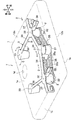
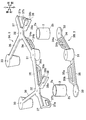
- FIG. 1 is a perspective view showing a fuel tank according to an embodiment of the present invention. It is the perspective view which similarly saw through the inside of a fuel tank. It is a disassembled perspective view which shows the correspondence of a connection member and a pair of upper and lower reinforcement members.
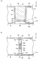
- 2A is a cross-sectional view taken along line AA in FIG. 2
- FIG. 2B is a cross-sectional view taken along line BB in FIG. 2A is a sectional view taken along the line CC of FIG. 2
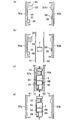
- FIG. 2B is a sectional view taken along the line DD of FIG. (A)-(d) is explanatory drawing which shows the assembly method of a connection member and a reinforcement member.
- FIGS. 1 to 3 are used as a reference. Each direction is set for convenience in describing the fuel tank T, and is not intended to limit the direction when the fuel tank T is mounted on the vehicle.
- a fuel tank T shown in FIGS. 1 and 2 is mounted on a moving means such as an automobile, a motorcycle, and a ship, and includes a fuel tank main body 1 and a connecting member 2 disposed inside the fuel tank main body 1 (FIG. 1). 2), and a reinforcing member 3 disposed outside the fuel tank main body 1.
- the fuel tank body 1 is a hollow container for storing fuel such as gasoline, and is formed of, for example, a thermoplastic resin including a barrier layer.
- the fuel tank body 1 is manufactured by, for example, blow molding.
- the fuel tank main body 1 includes an upper wall portion 1a, a lower wall portion 1b, and a side wall portion 1c that connects the upper wall portion 1a and the lower wall portion 1b.
- a pump mounting hole 1d is formed in the upper wall portion 1a of the fuel tank body 1 so as to penetrate therethrough.
- a pump (not shown) for pumping fuel out of the tank is mounted in the pump mounting hole 1d.
- buffer members 38A and 38A are arranged on the outer wall surface 12a of the upper wall portion 1a of the fuel tank body 1.
- the buffer members 38 ⁇ / b> A and 38 ⁇ / b> A have, for example, a cylindrical shape and are interposed between a vehicle body (not shown) and the fuel tank T.
- the buffer member 38A is formed of a material capable of absorbing an impact such as rubber.
- the connecting member 2 is a member that is attached to the inside of the fuel tank main body 1 when it is manufactured, and is formed of, for example, a thermoplastic resin. As shown in FIG. 4B, the connecting member 2 is welded to the upper end 2a welded to the inner wall 11a of the upper wall 1a and the inner wall 11b of the lower wall 1b. And a lower end 2b.
- the connecting member 2 is a member that partially connects and reinforces the opposing inner wall surfaces 11a and 11b. As shown in FIG. 2, in the present embodiment, two connection members 2 are arranged inside the fuel tank main body 1 with a gap therebetween.
- the reinforcing member 3 is a member that is inserted and attached from the outside when the fuel tank body 1 is manufactured.
- the reinforcing member 3 is preferably a member that is lightweight and can increase the rigidity of the fuel tank body 1.
- the reinforcing member 3 is formed of an aluminum alloy in this embodiment.
- the reinforcing member 3 may be formed by welding, but is integrally formed by die casting in this embodiment.
- a pair of reinforcing members 3 are disposed on the upper wall portion 1a and the lower wall portion 1b facing each other.
- the upper reinforcing member 3A has a shape along the outer wall surface 12a of the upper wall portion 1a
- the lower reinforcing member 3B has a shape along the outer surface 12b of the lower wall portion 1b. Since the reinforcing member 3A and the reinforcing member 3B have a common portion, the upper reinforcing member 3A will be described below with reference to FIG. 3 and the like, and then the lower reinforcing member 3B will be described.
- the reinforcing member 3A includes a first base portion 31, a second base portion 32, and a third base portion 33 having different shapes, and extending portions 34 to 38 extending along the outer wall surface 12a.
- the first base portion 31 is disposed at a substantially central portion in the left-right direction on the front side of the fuel tank body 1 (see FIGS. 1 and 2).
- the first base portion 31 has a substantially truncated cone shape whose diameter is reduced downward.
- the first base portion 31 is connected to an extending portion 34 extending to the right side and an extending portion 35 extending to the left side.
- the first base portion 31 of the reinforcing member 3A is integrated with a first protrusion 111 protruding inside the upper wall portion 1a. Since the first base portion 31 and the first protrusion 111 are integrated, the peripheral wall portion 1 a 1 and the bottom portion 1 a 2 of the first protrusion 111 have a shape along the shape of the first base portion 31.
- the second base portion 32 of the reinforcing member 3A has a circular flat plate shape.
- the second base portion 32 is disposed one by one on the left side and the right side of the first base portion 31 at positions corresponding to the connection members 2 and 2.
- the left second base portion 32 is connected to the first base portion 31 via the extending portion 35.
- the left second base portion 32 is connected to an extending portion 36 extending rearward, an extending portion 37 extending leftward, and an extending portion 38 extending frontward.
- the right second base portion 32 is connected to the first base portion 31 via the extending portion 34.
- an extension portion 36 extending rearward, an extension portion 37 extending rightward, and an extension portion 38 extending frontward are connected to the right second base portion 32.
- the second base portion 32 of the reinforcing member 3A is integrated with a second protrusion 121 protruding inside the upper wall portion 1a. Since the second base portion 32 and the second protrusion 121 are integrated, the step portion 1a3 and the bottom portion 1a4 of the second protrusion 121 have a concave shape along the shape of the second base portion 32.
- the upper end portion 2a of the connection member 2 is welded to the lower surface (the inner wall surface 11a of the upper wall portion 1a) of the bottom portion 1a4 of the second protrusion 121.
- the third base portion 33 is arranged one by one on the left side and the right side on the rear side of the fuel tank body 1.
- the third base portion 33 has a substantially truncated cone shape whose diameter is reduced downward.
- the left third base portion 33 is connected to the left second base portion 32 via an extending portion 36.
- the right third base portion 33 is connected to the right second base portion 32 via an extending portion 36.
- the third base portion 33 is integrated with a third protrusion 131 protruding inside the upper wall portion 1a. Since the third base portion 33 and the third protrusion portion 131 are integrated, the peripheral wall portion 1a5 and the bottom portion 1a6 of the third protrusion portion 131 are shaped along the shape of the third base portion 33.
- the third protrusion 131 faces the fourth protrusion 141 that protrudes inside the lower wall portion 1b.
- the fourth protrusion 141 includes a step 1b5 and a bottom 1b6.
- the lower surface of the bottom portion 1a6 of the third protrusion 131 is abutted against and welded to the upper surface of the bottom portion 1b6 of the fourth protrusion 141.
- the extending portion 35 connects the first base portion 31 and the left-side second base portion 32.
- the extending portion 35 includes a protruding portion 35 a that protrudes toward the inside (downward) of the fuel tank body 1.
- a hole 35b having a substantially trapezoidal cross section is formed inside the protrusion 35a.
- the extending portion 35 is integrated with a fifth protrusion 151 that protrudes inside the upper wall portion 1a. Since the extending part 35 and the fifth protruding part 151 are integrated, the fifth protruding part 151 has a shape along the shape of the extending part 35.
- the fifth protrusion 151 includes a bottom portion 15 a and a wall portion 15 b along the shape of the extending portion 35.
- the wall portion 15b is formed by the resin entering the hole portion 35b of the extending portion 35.
- the extending portion 34 connects the first base portion 31 and the second base portion 32 on the right side.
- the extending part 34 includes a projecting part 34 a that projects toward the inside (downward) of the fuel tank body 1.
- a hole 34b having a substantially square cross section is formed inside the protrusion 34a.
- Two hole portions 34 b are arranged in parallel in the extending direction of the extending portion 34.
- the extension part 34 is integrated with the fifth protrusion 151 that protrudes to the inside of the upper wall part 1a in the same manner as the extension part 35 described above (see FIG. 5B). That is, the fifth protrusion 151 includes a bottom portion 15 a and a wall portion 15 b along the shape of the extending portion 34.
- the wall portion 15b is formed by the resin entering the hole 34b of the extending portion 34.
- the extending portion 36 connects the second base portion 32 and the third base portion 33 on each of the left side and the right side of the fuel tank body 1.
- the extending part 36 has a flat plate shape.
- the extending portion 37 is connected to the left second base portion 32 and the right second base portion 32 of the fuel tank body 1.
- the extending portion 37 includes a protruding portion 37 a that protrudes toward the inside (downward) of the fuel tank body 1.
- a hole 37b having a substantially square cross section is formed in the protruding portion 37a.
- the extending portion 37 is integrated with a not-shown protruding portion that protrudes inside the upper wall portion 1a. Similar to the fifth protrusion 151 described above, the protrusion is formed by fixing the resin along the shape of the protrusion 37a during molding and entering the resin into the hole 37b.
- the extending portion 38 is connected to the left second base portion 32 and the right second base portion 32 of the fuel tank body 1, respectively.
- the extending portion 38 includes a plate-like protruding portion 38a connected to the second base portion 32, and a horizontal plate portion 38b provided at the tip end portion of the protruding portion 38a.
- the horizontal plate portion 38b is formed wider than the plate thickness of the protruding portion 38a.
- the extending portions 38 and 38 are extended to positions corresponding to the buffer members 38 ⁇ / b> A and 38 ⁇ / b> A. That is, the buffer member 38 ⁇ / b> A is disposed on the horizontal plate portion 38 b of the extending portion 38.
- the reinforcing member 3 ⁇ / b> B includes a first base portion 31, second base portions 32 and 32, and extending portions 34 and 35.
- the first base portion 31, the second base portions 32 and 32, and the extending portions 34 and 35 of the reinforcing member 3B are formed substantially the same as the respective portions of the reinforcing member 3A, and are symmetrical with respect to the reinforcing member 3A in the vertical direction. It is arranged to become.
- the first base portion 31 has a substantially truncated cone shape whose diameter is reduced upward, and faces the first base portion 31 of the reinforcing member 3A.
- the first base portion 31 of the reinforcing member 3B includes an extending portion 34 and an extending portion 35, similarly to the first base portion 31 of the reinforcing member 3A.
- the first base portion 31 of the reinforcing member 3B is integrated with a second protrusion 112 protruding inside the lower wall portion 1b. Since the 1st base 31 and the 2nd protrusion 112 are integrated, the surrounding wall part 1b1 and the bottom part 1b2 of the 2nd protrusion 112 become a shape along the shape of the 1st base 31.
- FIG. The bottom 1a2 of the first protrusion 111 and the bottom 1b2 of the second protrusion 112 are abutted and fixed by welding.
- the second base 32 of the reinforcing member 3B is disposed at a position corresponding to the connecting members 2 and 2 as shown in FIG.
- the left second base portion 32 is connected to the first base portion 31 via the extending portion 35
- the right second base portion 32 is connected to the first base portion 31 via the extending portion 34.
- the reinforcing member 3B does not have the extending portions 36 to 38 described above. However, the extending portions 36 to 38 may be provided on the second base portion 32.
- the second base portion 32 of the reinforcing member 3B is integrated with a second protrusion 122 that protrudes inside the lower wall portion 1b. Since the second base portion 32 and the second protrusion portion 122 are integrated, the step portion 1b3 and the bottom portion 1b4 of the second protrusion portion 122 have a concave shape along the shape of the second base portion 32.
- the lower end 2b of the connection member 2 is welded to the upper surface of the bottom 1b4 of the second protrusion 122 (the inner wall 11b of the lower wall 1b).
- the extending portion 35 of the reinforcing member 3B is integrated with a fifth protrusion 151 protruding inside the lower wall portion 1b as shown in FIG. 5 (b).
- the tip (lower end) of the fifth protrusion 151 on the upper wall 1a side and the tip (upper end) of the fifth protrusion 151 on the lower wall 1b side are welded together.
- the extension part 34 of the reinforcing member 3B is integrated with the fifth protrusion 151 protruding inside the lower wall part 1b, like the extension part 35.
- the tip (lower end) of the fifth protrusion 151 on the upper wall 1a side and the tip (upper end) of the fifth protrusion 151 on the lower wall 1b side are welded together.
- the extending portions 34 and the extending portions 35 of the reinforcing members 3A and 3B are welded so as to face each other up and down. Can play a function.
- FIG. 6 is a schematic cross-sectional view showing a manufacturing procedure, where (a) is a view showing a pair of molds 50a and 50b for manufacturing the fuel tank T, as seen from the direction of the arrow X shown in FIG. (Reinforcing members A and B are shown in cross section).
- FIG. 6B is a view showing the parison arranged between the molds
- FIG. 6C is a view showing a state in which the molds are clamped.
- FIG. 6D is a view showing a state where a fuel tank molded product is taken out from each mold.
- the manufacturing method of the fuel tank T includes a preparation process, a parison arrangement process, a suction process, a connecting member attachment process, a blow process, and a demolding process.
- the reinforcing member 3A is held in one mold 50a, and the reinforcing member 3B is held in the other mold 50b.
- the molds 50a and 50b are united together to form the fuel tank T.
- the concave portion of the mold 50a and the concave portion of the mold 50b are arranged in an opposing state.
- the molding die 50b is provided with a projecting mold part 50b1 for forming the fourth projecting part 141.
- the preparation step is a step of setting the reinforcing member 3A in the mold 50a and setting the reinforcing member 3B in the mold 50b.
- the mold 50a has holding means (not shown) that holds the reinforcing member 3A
- the mold 50b has holding means (not shown) that holds the reinforcing member 3B.
- the surface of the reinforcing member 3A is in surface contact with the molding surface of the molding die 50a.
- the surface of the reinforcing member 3B is in surface contact with the molding surface of the molding die 50b.
- the holding means may be configured by providing magnets in the molding dies 50a and 50b, or by providing convex portions on the molding dies 50a and 50b and fitting concave members in the reinforcing members 3A and 3B. May be.
- the parison placement step is a step of placing a parison between the molds 50a and 50b.
- the parison 61 and the parison 62 are arranged between the respective molds 50a and 50b using a chuck (not shown) or the like.
- the reinforcing member 3 ⁇ / b> A is disposed outside one parison 61, and the reinforcing member 3 ⁇ / b> B is disposed outside the other parison 62.
- the suction step is a step of transferring the parisons 61 and 62 to the molds 50a and 50b by suction.
- the connecting member attaching step is a step of attaching the connecting members 2 and 2 to the parisons 61 and 62 transferred to the molding dies 50a and 50b.
- the connecting member attaching step for example, the upper end portions of the connecting members 2 and 2 are pushed into the parison 61 and attached using attaching means such as a robot arm.
- the method of attaching the connection member 2 is not particularly limited.
- a center mold (not shown) is installed between the molds 50a and 50b, and the connection member 2 is attached to the parison 61 using the center mold. (Or parison 62).
- the molds 50a and 50b are moved in the opposite direction and clamped. Then, air is blown into the molds 50a and 50b by blow means (not shown) to completely transfer the parisons 61 and 62 to the molds 50a and 50b.
- the parison 61 is transferred along the outer periphery of the reinforcing member 3A, and the parison 61 is mixed into the holes 34b and 35b.
- the parison 62 is transferred along the outer periphery of the reinforcing member 3B and the protruding portion 50b1, and the parison 62 enters the holes 34b and 35b.
- the connecting member 2 is welded to the parisons 61 and 62.
- the demolding step is a step of taking out the transferred parisons 61 and 62 from the molds 50a and 50b. As shown in FIG. 6D, in the demolding step, the molds 50a and 50b are opened to take out the molded product, and the burrs protruding from the upper and lower ends are cut. As shown in FIG. 1, the fuel tank T is completed when the pump mounting hole 1d is opened on the upper surface.
- the rigidity of the fuel tank main body 1 can be increased.
- the second base portions 32 and 32 of the reinforcing members 3 ⁇ / b> A and 3 ⁇ / b> B are disposed outside the connection member 2, and extending portions 34, 35, 36, 37 and 38 extending from the second base portions 32 and 32 are provided. ing.
- the second base portion 32 is also arranged in two sets corresponding to the connecting members 2.
- the rigidity of the fuel tank main body 1 can be improved as compared with the case where the connecting member 2 and the second base portion 32 are arranged one by one. Therefore, deformation of the fuel tank body 1 can be more effectively suppressed.
- the deformation between the first base 31 and the second base 32 is caused to extend to the extending portions 34 and 35. It can suppress suitably.
- the extension part 36 since the 2nd base 32 and the 3rd base 33 are connected by the extension part 36, the deformation
- the extending portions 34, 35, 37, and 38 are provided with protruding portions 34a, 35a, 37a, and 38a, respectively.
- the extending part 38 is extended to the position corresponding to the buffer member 38A, the rigidity in the vicinity of the buffer member 38A that easily receives an external force can be improved. For this reason, deformation of the fuel tank body 1 can be more effectively suppressed.
- the protrusion part 38a is arrange
- the reinforcing members 3A and 3B are disposed in pairs on the outer wall surfaces 12a and 12b facing each other, the rigidity of the fuel tank body 1 can be improved in a balanced manner.
- the reinforcing members 3A and 3B are inserted from the outside of the fuel tank body 1, they can be firmly fixed without rattling. Further, in the prior art, an assembling process for assembling the frame member to the fuel tank main body is required separately from the molding process of the fuel tank main body. On the other hand, in this embodiment, since the reinforcing members 3A and 3B can be inserted when the fuel tank body 1 is molded, the manufacturing cycle can be shortened.
- the outer wall surfaces 12a and 12b of the fuel tank main body 1 and the outer surfaces of the reinforcing members 3A and 3B can be flush with each other.
- the 1st base part 31 of the reinforcement member 3A and the 1st base part 31 of the reinforcement member 3B are faced
- a butt portion 115 is formed. That is, the inner wall surfaces 11 a and 11 b of the fuel tank body 1 can be connected to each other by the first protrusion 111 and the second protrusion 112. Thereby, the rigidity of the fuel tank body 1 can be further increased, and a wave eliminating function can be achieved.
- matching part 115 is formed by welding the 3rd protrusion 131 and the 4th protrusion 141 by the 3rd base 33 of the reinforcement member 3A. Yes. That is, the inner wall surfaces 11 a and 11 b of the fuel tank body 1 can be connected to each other by the third protrusion 131 and the fourth protrusion 141. Thereby, the rigidity of the fuel tank body 1 can be further increased, and a wave eliminating function can be achieved.
- first base portion 31 and the third base portion 33 disposed at positions corresponding to the abutting portions 115, and the extended portions 34 to 34 extending from the first base portion 31 and the third base portion 33 along the outer wall surfaces 12a and 12b. Since it has 36, the rigidity of the fuel tank main body 1 can be improved more similarly to the above-mentioned 2nd base 32. Therefore, the deformation of the fuel tank body 1 can be suppressed regardless of the positive pressure deformation and the negative pressure deformation of the fuel tank body 1.
- the connection member 2 and the abutting part 115 were provided, the structure provided with at least one may be sufficient.
- the present invention is not limited to the above-described embodiments, and can be variously modified as follows, for example.
- the first base 31, the second base 32, and the third base 33 are all connected by the extending portions 35, 34, etc., but the present invention is not limited to this, and only a part thereof is connected. It is good also as a structure which connects, It is good also as a structure which is not connected at all.
- the first base 31 and the third base 33 have a substantially truncated cone shape, and the second base 32 has a circular flat plate shape.
- the present invention is not limited to this, and various shapes can be adopted.
- the reinforcing member 3 is constituted by the pair of reinforcing members 3A and the reinforcing member 3B, it is not limited to this and may be constituted by only one of them. Further, the pair of reinforcing members 3A and the reinforcing member 3B may be symmetrical in the vertical direction (the same shape in the vertical direction).
Landscapes
- Engineering & Computer Science (AREA)
- Mechanical Engineering (AREA)
- Manufacturing & Machinery (AREA)
- Chemical & Material Sciences (AREA)
- Combustion & Propulsion (AREA)
- Life Sciences & Earth Sciences (AREA)
- Sustainable Development (AREA)
- Sustainable Energy (AREA)
- Transportation (AREA)
- General Engineering & Computer Science (AREA)
- Cooling, Air Intake And Gas Exhaust, And Fuel Tank Arrangements In Propulsion Units (AREA)
- Blow-Moulding Or Thermoforming Of Plastics Or The Like (AREA)
Abstract
燃料タンク本体の変形を効果的に抑制することができ、耐久性に優れる燃料タンクを提供する。燃料タンク本体(1)と、燃料タンク本体(1)の対向する内壁面(11a,11b)同士を部分的に接続する接続部材(2)または/および燃料タンク本体(1)の対向する内壁面(11a,11b)同士が部分的に突き合わされる突合部(115)と、燃料タンク本体(1)の外壁面(12a,12b)に一体的に設けられ、外壁面(12a,12b)を補強する補強部材(3A,3B)と、を備え、補強部材(3A,3B)は、接続部材(2)または/および突合部(115)に対応する位置に配置される基部(32,32)と、基部(32)から外壁面(12a,12b)に沿って延在する延在部(34,35)と、を備えている構成とした。
Description
本発明は、燃料タンクに関する。
自動車に搭載される燃料タンクとして、特許文献1に記載されたものが知られている。特許文献1の燃料タンクでは、樹脂燃料タンク本体の外周面に枠部材を設けた構造が記載されている。この燃料タンクによれば、枠部材によって燃料タンクの補強を図ることができる。
ところで、燃料タンクは、外気温の変化や排気系統の熱による温度変化などに起因する内圧変化によって正圧変形または負圧変形を起こす。特に、樹脂製の燃料タンクの場合、このような外的要因の影響を受けやすい。特許文献1の燃料タンクでは、枠部材によって燃料タンク本体の正圧変形を抑制することはできるが、負圧変形に対応することができないという問題があった。燃料タンク本体が負圧変形すると、燃料タンク本体の内部に配置されたバルブやポンプ等に悪影響が及ぶという問題がある。また、特許文献1の燃料タンクでは、枠部材が燃料タンク本体を周りから全体的に囲う態様であるため、枠部材が大型であり、燃料タンク本体の変形を効果的に抑制する態様とは言い難い。
本発明は、このような課題を解決するために創作されたものであり、燃料タンク本体の剛性を高めることができ、燃料タンク本体の変形を効果的に抑制することができる燃料タンクを提供することを課題とする。
前記課題を解決するため、本発明は、燃料タンク本体と、前記燃料タンク本体の対向する内壁面同士を部分的に接続する接続部材または/および前記燃料タンク本体の対向する内壁面同士が部分的に突き合わされる突合部と、前記燃料タンク本体の外壁面に一体的に設けられ、前記外壁面を補強する補強部材と、を備え、前記補強部材は、前記接続部材または/および前記突合部に対応する位置に配置される基部と、前記基部から前記外壁面に沿って延在する延在部と、を備えていることを特徴とする。
本発明によれば、対向する内壁面同士が接続部材によって部分的に接続されているため、または/および対向する内壁面同士が突合部によって部分的に突き合わされているため、燃料タンク本体の剛性を高めることができる。また、接続部材または/および突合部の外側に補強部材の基部が配置されるとともに、基部から延在する延在部を備えている。これにより、正圧変形または負圧変形の際に応力が作用する部位を効果的に補強できるため、剛性をより高めることができる。よって、燃料タンク本体の正圧変形および負圧変形に関わらず、燃料タンク本体の変形を効果的に抑制することができる。
また、前記接続部材または/および前記突合部は複数配置されており、前記基部は前記複数の接続部材または/および前記突合部に対応して複数配置されており、少なくとも二つの前記基部は、前記延在部を介して連結されていることが好ましい。
かかる構成によれば、接続部材または/および突合部とそれに対応する基部とが一つずつ配置されている場合に比べて、燃料タンク本体の剛性を向上させることができるため、燃料タンク本体の変形をより抑制することができる。また、少なくとも二つの基部が延在部を介して連結されるため、基部間の変形を延在部によって好適に抑制することができる。
また、前記延在部は、前記燃料タンク本体の内側に向けて突出する突出部を備えていることが好ましい。かかる構成によれば、燃料タンク本体の内壁面が内側に突出するため、燃料の波消し機能を奏することができる。また、補強部材自体の剛性も向上する。
また、前記燃料タンク本体の外壁面には、緩衝部材が設けられており、前記延在部は前記緩衝部材に対応する位置まで延設されていることが好ましい。
かかる構成によれば、外力を受け易い緩衝部材付近の剛性を向上させることができるため、燃料タンク本体の変形をより効果的に抑制することができる。
また、前記補強部材は、前記燃料タンク本体の対向する外壁面に一対配置されていることが好ましい。かかる構成によれば、燃料タンク本体の剛性をバランスよく向上させることができる。
本発明の燃料タンクによれば、燃料タンク本体の変形を効果的に抑制することができる。
以下、本発明の実施形態を、図面を参照して説明する。以下の説明において、「前後」、「左右」、「上下」を言うときは、図1~図3に示した方向を基準とする。なお、各方向は、燃料タンクTを説明する上で便宜上設定したものであり、燃料タンクTを車両に搭載したときの方向を限定する趣旨ではない。
図1,図2に示す燃料タンクTは、自動車やバイク並びに船舶等の移動手段に搭載されるものであり、燃料タンク本体1と、燃料タンク本体1の内側に配置される接続部材2(図2参照)と、燃料タンク本体1の外側に配置される補強部材3と、を備えている。
燃料タンク本体1は、ガソリン等の燃料を貯溜する中空容器であり、例えばバリア層を含んだ熱可塑性樹脂で形成されている。燃料タンク本体1は、例えばブロー成形等によって製造される。燃料タンク本体1は、図1に示すように、上壁部1aと、下壁部1bと、上壁部1aおよび下壁部1bを接続する側壁部1cと、を備え、幅広で上下方向に薄い形状を呈する。燃料タンク本体1の上壁部1aには、ポンプ取付穴1dが貫通して形成されている。ポンプ取付穴1dには、燃料をタンク外へ汲み出すポンプ(図示せず)が取り付けられる。
燃料タンク本体1の上壁部1aの外壁面12aには、図1に示すように、緩衝部材38A,38Aが配置されている。緩衝部材38A,38Aは、例えば円柱状を呈し、図示しない車体と燃料タンクTとの間に介設される部材である。緩衝部材38Aは、例えばゴム等の衝撃を吸収することができる材料で形成されている。
接続部材2は、燃料タンク本体1の製造時にその内側に取り付けられる部材であり、例えば熱可塑性樹脂で形成されている。接続部材2は円筒状を呈しており、図4(b)に示すように、上壁部1aの内壁面11aに溶着される上端部2aと、下壁部1bの内壁面11bに溶着される下端部2bとを備えている。接続部材2は、対向する内壁面11a,11b同士を部分的に接続して補強する部材である。図2に示すように、接続部材2は、本実施形態では、燃料タンク本体1の内部に間隔を空けて2つ配置されている。
補強部材3は、図2および図3に示すように、燃料タンク本体1の製造時にその外側からインサートされて取り付けられる部材である。補強部材3は、軽量であり、かつ、燃料タンク本体1の剛性を高めることができる部材であることが好ましい。補強部材3は、本実施形態ではアルミニウム合金で形成されている。補強部材3は、溶接により形成してもよいが、本実施形態ではダイキャストで一体成形されている。
補強部材3は、対向する上壁部1aおよび下壁部1bに一対配置されている。上側の補強部材3Aは、上壁部1aの外壁面12aに沿う形状を呈し、また、下側の補強部材3Bは、下壁部1bの外面12bに沿う形状を呈している。補強部材3Aおよび補強部材3Bは、共通する部分を備えているので、以下では、図3等を参照して上側の補強部材3Aについて説明し、その後、下側の補強部材3Bについて説明する。
補強部材3Aは、相互に形状の異なる第一基部31、第二基部32および第三基部33と、外壁面12aに沿って延在する延在部34~38と、を備えている。第一基部31は、燃料タンク本体1の前側において左右方向の略中央部に配置されている(図1,図2参照)。第一基部31は、下方へ向けて縮径された略円錐台形状を呈している。第一基部31には、右側に延びる延在部34および左側に延びる延在部35が接続されている。
補強部材3Aの第一基部31は、図4(a)に示すように、上壁部1aの内側に突出する第一突部111に一体化されている。第一基部31と第一突部111とが一体化されているため、第一突部111の周壁部1a1および底部1a2は、第一基部31の形状に沿った形状となる。
補強部材3Aの第二基部32は、円形平板形状を呈している。第二基部32は、接続部材2,2に対応する位置となる、第一基部31の左側および右側に一つずつ配置されている。左側の第二基部32は、延在部35を介して第一基部31に連結されている。左側の第二基部32には、後側に延びる延在部36、左側に延びる延在部37、および前側に延びる延在部38が接続されている。右側の第二基部32は、延在部34を介して第一基部31に連結されている。右側の第二基部32には、左側の第二基部32と同様に、後側に延びる延在部36、右側に延びる延在部37、および前側に延びる延在部38が接続されている。
補強部材3Aの第二基部32は、図4(b)に示すように、上壁部1aの内側に突出する第二突部121に一体化されている。第二基部32と第二突部121とが一体化されているため、第二突部121の段部1a3と底部1a4とは、第二基部32の形状に沿った凹形状となる。接続部材2の上端部2aは、第二突部121の底部1a4の下面(上壁部1aの内壁面11a)に溶着されている。
第三基部33は、図2に示すように、燃料タンク本体1の後側において左側および右側に一つずつ配置されている。第三基部33は、下方へ向けて縮径された略円錐台形状を呈している。左側の第三基部33は、延在部36を介して左側の第二基部32に連結されている。右側の第三基部33は、延在部36を介して右側の第二基部32に連結されている。
第三基部33は、図5(a)に示すように、上壁部1aの内側に突出する第三突部131に一体化されている。第三基部33と第三突部131とが一体化されているため、第三突部131の周壁部1a5および底部1a6は、第三基部33の形状に沿った形状となる。第三突部131は、下壁部1bの内側に突出する第四突部141に対向している。第四突部141は、段部1b5と底部1b6とを備えている。第三突部131の底部1a6の下面は、第四突部141の底部1b6の上面に突き合わされて溶着されている。
延在部35は、図2,図3に示すように、第一基部31と左側の第二基部32とを連結している。延在部35は、燃料タンク本体1の内側に向けて(下方へ向けて)突出する突出部35aを備えている。突出部35aの内側には、断面略台形状の孔部35bが形成されている。延在部35は、図5(b)に示すように、上壁部1aの内側に突出する第五突部151に一体化されている。延在部35と第五突部151とが一体化されているため、第五突部151は、延在部35の形状に沿った形状となる。すなわち、第五突部151は、延在部35の形状に沿って、底部15aと、壁部15bとを備えている。後記する成形時に、延在部35の孔部35bに樹脂が入り込むことにより、壁部15bが形成される。
延在部34は、図2,図3に示すように、第一基部31と右側の第二基部32とを連結している。延在部34は、燃料タンク本体1の内側に向けて(下方へ向けて)突出する突出部34aを備えている。突出部34aの内側には、断面略四角形状の孔部34bが形成されている。孔部34bは、延在部34の延在方向に二つ並設されている。延在部34は、前記した延在部35と同様に、上壁部1aの内側に突出する第五突部151に一体化されている(図5(b)参照)。すなわち、第五突部151は、延在部34の形状に沿って、底部15aと、壁部15bとを備えている。後記する成形時に、延在部34の孔部34bに樹脂が入り込むことにより、壁部15bが形成される。
延在部36は、燃料タンク本体1の左側および右側のそれぞれにおいて、第二基部32と第三基部33とを連結している。延在部36は、扁平板形状を呈している。
延在部37は、図3に示すように、燃料タンク本体1の左側の第二基部32、および右側の第二基部32にそれぞれ接続されている。延在部37は、燃料タンク本体1の内側に向けて(下方へ向けて)突出する突出部37aを備えている。突出部37aには、断面略四角形状の孔部37bが形成されている。延在部37は、上壁部1aの内側に突出する図示しない突部に一体化されている。突部は、前記した第五突部151と同様に、成形時に突出部37aの形状に沿って樹脂が定着するとともに、孔部37bに樹脂が入り込むことにより成形される。
延在部38は、燃料タンク本体1の左側の第二基部32、および右側の第二基部32にそれぞれ接続されている。延在部38は、第二基部32に接続される板状の突出部38aと、突出部38aの先端部に設けられた横板部38bと、を備えている。横板部38bは、突出部38aの板厚よりも幅広に形成されている。延在部38,38は、図1に示すように、緩衝部材38A,38Aに対応する位置まで延設されている。つまり、緩衝部材38Aは、延在部38の横板部38bの上に配置されている。
補強部材3Bは、第一基部31と、第二基部32,32と、延在部34,35とで構成されている。補強部材3Bの第一基部31、第二基部32,32及び延在部34,35は、補強部材3Aの各部位と略同等に形成されており、補強部材3Aに対して上下方向に線対称となるように配置されている。
補強部材3Bにおいて、第一基部31は、上方へ向けて縮径された略円錐台形状を呈しており、補強部材3Aの第一基部31に対向している。補強部材3Bの第一基部31は、補強部材3Aの第一基部31と同様に、延在部34および延在部35を備えている。
補強部材3Bの第一基部31は、図4(a)に示すように、下壁部1bの内側に突出する第二突部112に一体化されている。第一基部31と第二突部112とが一体化されているため、第二突部112の周壁部1b1と底部1b2とは、第一基部31の形状に沿った形状となる。第一突部111の底部1a2と第二突部112の底部1b2とは、突き合わされて溶着により固定されている。
補強部材3Bの第二基部32は、図4(b)に示すように、接続部材2,2に対応する位置に配置されている。左側の第二基部32は、延在部35を介して第一基部31に連結され、また、右側の第二基部32は、延在部34を介して第一基部31に連結されている。なお、補強部材3Bは、前記した延在部36~38を有していないが、これらの延在部36~38を第二基部32に設けても差し支えない。
補強部材3Bの第二基部32は、下壁部1bの内側に突出する第二突部122に一体化されている。第二基部32と第二突部122とが一体化されているため、第二突部122の段部1b3と底部1b4とは、第二基部32の形状に沿った凹形状となる。接続部材2の下端部2bは、第二突部122の底部1b4の上面(下壁部1bの内壁面11b)に溶着されている。
補強部材3Bの延在部35は、図5(b)に示すように、下壁部1bの内側に突出する第五突部151に一体化されている。上壁部1a側の第五突部151の先端(下端)と下壁部1b側の第五突部151の先端(上端)とは溶着されている。
補強部材3Bの延在部34は、延在部35と同様に、下壁部1bの内側に突出する第五突部151に一体化されている。上壁部1a側の第五突部151の先端(下端)と下壁部1b側の第五突部151の先端(上端)とは溶着されている。このように、補強部材3A,3Bの延在部34同士および延在部35同士は、上下に突き合わされて溶着されているので、燃料タンク本体1の剛性をより高めることができるとともに、波消し機能を奏することができる。
次に、燃料タンクTの製造手順を図6を参照して説明する。図6は製造手順を示した模式平断面図であって、(a)は燃料タンクTを製造する一対の成形型50a,50bを示す図であり、図2に示す矢印X方向から見た状態に対応している(補強部材A,Bは断面で図示している)。図6(b)は成形型間に配置されたパリソンを示す図であり、図6(c)は各成形型を型締めした状態を示す図である。図6(d)は各成形型から燃料タンク成形品を取り出した状態を示す図である。
燃料タンクTの製造方法は、準備工程、パリソン配置工程、吸引工程、接続部材取付工程、ブロー工程、脱型工程を含んでいる。図6(a)に示すように、一方の成形型50aには、補強部材3Aが保持され、他方の成形型50bには、補強部材3Bが保持される。各成形型50a,50bは、一体に合わさって、燃料タンクTを形成するものである。図のように、成形型50aの凹部と成形型50bの凹部とが対向状態に配置される。なお、成形型50bには、第四突部141を形成するための突型部50b1が設けられている。
準備工程は、成形型50aに補強部材3Aをセットし、成形型50bに補強部材3Bをセットする工程である。成形型50aは、補強部材3Aを保持する保持手段(図示省略)を有しており、また、成形型50bは、補強部材3Bを保持する保持手段(図示省略)を有している。補強部材3Aの表面は、成形型50aの成形面と面接触する。補強部材3Bの表面は成形型50bの成形面と面接触する。
補強部材3A,3Bを保持手段を介してセットすることにより、成形時における補強部材3A,3Bの傾倒や位置ずれを防ぐことができる。なお、保持手段は、成形型50a,50bに磁石を設けて構成したり、成形型50a,50bに凸部を設けるとともに、補強部材3A,3Bに凹部を設けて嵌め合わせることで構成したりしてもよい。
パリソン配置工程は、各成形型50a,50bの間にパリソンを配置する工程である。図6(b)に示すように、パリソン配置工程では、各成形型50a,50bの間に、チャック(不図示)等を用いてパリソン61およびパリソン62を配置する。一方のパリソン61の外側には補強部材3Aが配置され、他方のパリソン62の外側には補強部材3Bが配置される。
吸引工程は、吸引により成形型50a,50bにパリソン61,62を転写させる工程である。接続部材取付工程は、成形型50a,50bに転写されたパリソン61,62に接続部材2,2を取り付ける工程である。接続部材取付工程では、例えば、ロボットアーム等の取付手段を用いて接続部材2,2の上端部をパリソン61に押し込んで取り付ける。なお、接続部材2を取り付ける方法は、特に制限されるものではなく、例えば、成形型50a,50bの間にセンター型(図示省略)を設置し、センター型を利用して接続部材2をパリソン61(又はパリソン62)に取り付けてもよい。
ブロー工程は、各成形型50a,50bを対向方向に移動させて型締めする。そして、図示しないブロー手段によって成形型50a,50bの内部にエアーを吹き付けて、パリソン61,62を成形型50a,50bに完全に転写させる。この際、補強部材3Aの外周に沿うようにしてパリソン61が転写されるとともに、孔部34b,35bにパリソン61が入り混む。また、補強部材3Bおよび突型部50b1の外周に沿うようにしてパリソン62が転写されるとともに、孔部34b,35bにパリソン62が入り込む。また、接続部材2がパリソン61,62に対して溶着される。
脱型工程は、転写されたパリソン61,62を成形型50a,50bから取り出す工程である。図6(d)に示すように、脱型工程では、各成形型50a,50bを開いて成形品を取り出し、上下端に突き出たバリを切断する。そして、図1に示すように、上面にポンプ取付穴1dを開口すれば燃料タンクTが完成する。
以上説明した本実施形態の燃料タンクTによれば、対向する内壁面11a,11b同士が接続部材2によって接続されているため、燃料タンク本体1の剛性を高めることができる。また、接続部材2の外側に補強部材3A,3Bの第二基部32,32が配置されるとともに、第二基部32,32から延在する延在部34,35,36,37,38を備えている。これにより、正圧変形または負圧変形の際に応力が作用する部位を効果的に補強できるため、燃料タンク本体1の剛性をより高めることができる。よって、燃料タンク本体1の正圧変形および負圧変形に関わらず、燃料タンク本体1の変形を抑制することができる。
また、接続部材2は二つ配置されるとともに、第二基部32も接続部材2に対応して二組ずつ配置されている。これによって、接続部材2および第二基部32が一つずつ配置されている場合に比べて、燃料タンク本体1の剛性を向上させることができる。したがって、燃料タンク本体1の変形をより効果的に抑制することができる。また、例えば、第一基部31と第二基部32とが延在部34,35を介して連結されるため、第一基部31と第二基部32との間の変形を延在部34,35によって好適に抑制することができる。
なお、第二基部32と第三基部33とが延在部36によって連結されるため、第二基部32と第三基部33との間の変形を延在部36によって好適に抑制することができる。この場合、第一基部31と第三基部33とを図示しない延在部を用いて連結するように構成してもよい。また、第三基部33同士を図示しない延在部を用いて連結するように構成してもよい。
また、延在部34,35,37,38は、それぞれ突出部34a,35a,37a,38a備えている。これにより、燃料タンク本体1の内壁面11a,11bが内側に突出するため、燃料の波消し機能を奏することができる。また、補強部材3A,3B自体の剛性も向上する。さらに、成形時に補強部材3A,3Bの形状に沿うようにパリソン61,62を転写させることにより、補強部材3A,3Bと燃料タンク本体1とを強固に一体化することができる。
また、延在部38は緩衝部材38Aに対応する位置まで延設されているので、外力を受け易い緩衝部材38A付近の剛性を向上させることができる。このため、燃料タンク本体1の変形をより効果的に抑制することができる。また、突出部38aは、横板部38bに対して垂直に配置されているため、延在部38の剛性を高めることができる。
また、補強部材3A,3Bは、燃料タンク本体1の対向する外壁面12a,12bに一対配置されているので、燃料タンク本体1の剛性をバランスよく向上させることができる。
また、従来技術では、燃料タンク本体と枠部材との成形誤差等により、枠部材の内部で燃料タンク本体がガタつくおそれがある。しかし、本実施形態では、補強部材3A,3Bを燃料タンク本体1の外側から挿入するため、ガタつくことなく強固に固着することができる。また、従来技術では、燃料タンク本体の成形工程とは別に、燃料タンク本体に枠部材を組み付ける組付工程を要する。これに対し、本実施形態では、燃料タンク本体1の成形時に補強部材3A,3Bをインサートできるため、製造サイクルの短縮化を図ることができる。また、燃料タンク本体1に補強部材3A,3Bを挿入できるため、燃料タンク本体1の外壁面12a,12bと補強部材3A,3Bとの外面とを面一にすることができる。
また、本実施形態では、図4(a)に示すように、補強部材3Aの第一基部31と、補強部材3Bの第一基部31とを突き合わせて第一突部111,112を溶着させることで突合部115が形成されている。つまり、第一突部111と第二突部112とで燃料タンク本体1の内壁面11a,11b同士を接続することができる。これにより、燃料タンク本体1の剛性をより高めることができるとともに、波消し機能を奏することができる。
また、本実施形態では、図5(a)に示すように、補強部材3Aの第三基部33によって第三突部131と第四突部141とを溶着させることで突合部115が形成されている。つまり、第三突部131と第四突部141とで燃料タンク本体1の内壁面11a,11b同士を接続することができる。これにより、燃料タンク本体1の剛性をより高めることができるとともに、波消し機能を奏することができる。また、突合部115に対応する位置に配置される第一基部31,第三基部33と、第一基部31,第三基部33から外壁面12a,12bに沿って延在する延在部34~36を有しているので、前記した第二基部32と同様に、燃料タンク本体1の剛性をより高めることができる。よって、燃料タンク本体1の正圧変形および負圧変形に関わらず、燃料タンク本体1の変形を抑制することができる。なお、本実施形態では、接続部材2と突合部115との両方を設けたが、少なくとも一方が備わる構成であってもよい。
以上本発明の実施形態について説明したが、本発明は、上記した実施形態に限定されることはなく、例えば、以下のように種々変形することができる。
例えば、前記実施形態では、第一基部31、第二基部32および第三基部33を延在部35,34等ですべて連結する構成としたが、これに限られることはなく、一部のみを連結する構成としてもよいし、全く連結しない構成としてもよい。
例えば、前記実施形態では、第一基部31、第二基部32および第三基部33を延在部35,34等ですべて連結する構成としたが、これに限られることはなく、一部のみを連結する構成としてもよいし、全く連結しない構成としてもよい。
また、第一基部31および第三基部33は略円錐台形状とし、第二基部32は円形平板形状としたが、これに限られることはなく、種々の形状のものを採用し得る。
また、補強部材3は、一対の補強部材3Aと補強部材3Bとで構成したが、これに限られることはなく、一方のみで構成してもよい。また、一対の補強部材3Aと補強部材3Bとを上下で対称形状(上下で同一形状)としてもよい。
1 燃料タンク本体
2 接続部材
3 補強部材
3A,3B 補強部材
11a,11b 内壁面
12a,12b 外壁面
31 第一基部
32 第二基部
33 第三基部
34~38 延在部
34a,35a 枠部(突出部)
37a 突出部
38a 突出部
38A 緩衝部材
T 燃料タンク
2 接続部材
3 補強部材
3A,3B 補強部材
11a,11b 内壁面
12a,12b 外壁面
31 第一基部
32 第二基部
33 第三基部
34~38 延在部
34a,35a 枠部(突出部)
37a 突出部
38a 突出部
38A 緩衝部材
T 燃料タンク
Claims (6)
- 燃料タンク本体と、
前記燃料タンク本体の対向する内壁面同士を部分的に接続する接続部材または/および前記燃料タンク本体の対向する内壁面同士が部分的に突き合わされる突合部と、
前記燃料タンク本体の外壁面に一体的に設けられ、前記外壁面を補強する補強部材と、
を備え、
前記補強部材は、
前記接続部材または/および前記突合部に対応する位置に配置される基部と、
前記基部から前記外壁面に沿って延在する延在部と、を備えていることを特徴とする燃料タンク。 - 前記接続部材または/および前記突合部は複数配置されており、
前記基部は前記複数の接続部材または/および前記突合部に対応して複数配置されており、
少なくとも二つの前記基部は、前記延在部を介して連結されていることを特徴とする請求項1に記載の燃料タンク。 - 前記延在部は、前記燃料タンク本体の内側に向けて突出する突出部を備えていることを特徴とする請求項1または請求項2に記載の燃料タンク。
- 前記突出部は凹部または孔部を備えていることを特徴とする請求項3に記載の燃料タンク。
- 前記燃料タンク本体の前記外壁面には、緩衝部材が設けられており、
前記延在部は、前記緩衝部材に対応する位置まで延設されていることを特徴とする請求項1に記載の燃料タンク。 - 前記補強部材は、前記燃料タンク本体の対向する前記外壁面に一対配置されていることを特徴とする請求項1に記載の燃料タンク。
Priority Applications (4)
| Application Number | Priority Date | Filing Date | Title |
|---|---|---|---|
| US15/569,823 US10322630B2 (en) | 2015-04-27 | 2016-03-09 | Fuel tank |
| JP2017515424A JP6298931B2 (ja) | 2015-04-27 | 2016-03-09 | 燃料タンク |
| CN201680023867.6A CN107531145B (zh) | 2015-04-27 | 2016-03-09 | 一种燃料箱 |
| EP16786213.5A EP3290249B1 (en) | 2015-04-27 | 2016-03-09 | Fuel tank |
Applications Claiming Priority (2)
| Application Number | Priority Date | Filing Date | Title |
|---|---|---|---|
| JP2015090204 | 2015-04-27 | ||
| JP2015-090204 | 2015-04-27 |
Publications (1)
| Publication Number | Publication Date |
|---|---|
| WO2016174936A1 true WO2016174936A1 (ja) | 2016-11-03 |
Family
ID=57198282
Family Applications (1)
| Application Number | Title | Priority Date | Filing Date |
|---|---|---|---|
| PCT/JP2016/057308 Ceased WO2016174936A1 (ja) | 2015-04-27 | 2016-03-09 | 燃料タンク |
Country Status (5)
| Country | Link |
|---|---|
| US (1) | US10322630B2 (ja) |
| EP (1) | EP3290249B1 (ja) |
| JP (1) | JP6298931B2 (ja) |
| CN (1) | CN107531145B (ja) |
| WO (1) | WO2016174936A1 (ja) |
Cited By (1)
| Publication number | Priority date | Publication date | Assignee | Title |
|---|---|---|---|---|
| WO2023008206A1 (ja) * | 2021-07-26 | 2023-02-02 | 八千代工業株式会社 | 燃料タンク |
Families Citing this family (4)
| Publication number | Priority date | Publication date | Assignee | Title |
|---|---|---|---|---|
| CN110722980A (zh) * | 2018-07-17 | 2020-01-24 | 泽菲罗斯有限公司 | 用于燃料箱的结构增强件 |
| EP3744551B1 (de) * | 2019-05-31 | 2022-04-13 | TI Automotive Technology Center GmbH | Kraftstoffbehälter mit versteifungseinrichtung |
| KR102703386B1 (ko) | 2019-11-07 | 2024-09-04 | 현대자동차주식회사 | 자동차용 연료탱크 강성 보강 장치 |
| BE1031806B1 (fr) * | 2023-07-17 | 2025-02-17 | Plastic Omnium Advanced Innovation & Res | Réservoir d'essence équipé d'un renfort de sa paroi périphérique |
Citations (2)
| Publication number | Priority date | Publication date | Assignee | Title |
|---|---|---|---|---|
| JPS63258750A (ja) * | 1987-04-16 | 1988-10-26 | 東燃化学株式会社 | バツフル付きプラスチツクタンク |
| JP2014148227A (ja) * | 2013-01-31 | 2014-08-21 | Yachiyo Industry Co Ltd | 燃料タンクの車体取付構造 |
Family Cites Families (27)
| Publication number | Priority date | Publication date | Assignee | Title |
|---|---|---|---|---|
| US2724418A (en) * | 1953-03-02 | 1955-11-22 | Goodrich Co B F | Fluid-receiving container with volumeresponsive pressure-relief and overflow valve assembly |
| US3596794A (en) * | 1969-11-18 | 1971-08-03 | Phillips Petroleum Co | Supporting apparatus |
| GB1573510A (en) * | 1977-01-11 | 1980-08-28 | Northern Eng Ind | Liquid storage tanks made of panels |
| IT8153149U1 (it) * | 1981-04-16 | 1982-10-16 | Fiat Auto Spa | Serbatoio per combustibile particolarmente per autoveicoli |
| US6294127B1 (en) * | 1998-05-15 | 2001-09-25 | The Moore Company | Fuel tank having molded reinforcements and method of making same |
| US6338420B1 (en) * | 1999-06-08 | 2002-01-15 | Delphi Technologies, Inc. | Motor vehicle fuel tank and method |
| DE10008985A1 (de) * | 2000-02-25 | 2001-08-30 | Linde Ag | Speicherbehälter |
| JP4014907B2 (ja) * | 2002-03-27 | 2007-11-28 | 日新製鋼株式会社 | 耐食性に優れたステンレス鋼製の自動車用燃料タンクおよび給油管 |
| DE10329990B3 (de) * | 2003-07-02 | 2005-04-21 | Benteler Automobiltechnik Gmbh | Druckgastank |
| JP2006192919A (ja) * | 2005-01-11 | 2006-07-27 | Fts:Kk | 自動車用燃料タンクおよびその製造方法 |
| US7284417B2 (en) * | 2005-07-28 | 2007-10-23 | Reynolds Charles W | Tire monitor |
| JP4775080B2 (ja) * | 2006-04-03 | 2011-09-21 | 日産自動車株式会社 | 燃料タンク構造 |
| JP2009166753A (ja) | 2008-01-18 | 2009-07-30 | Yamaha Motor Co Ltd | 燃料タンク,該燃料タンクを備えた自動二輪車及び該燃料タンクの製造方法 |
| KR100967815B1 (ko) * | 2008-02-26 | 2010-07-05 | 대우조선해양 주식회사 | 부유식 해상구조물의 lng 저장탱크 |
| JP4832480B2 (ja) | 2008-08-08 | 2011-12-07 | 八千代工業株式会社 | 燃料タンクの保護板取付構造 |
| DE102009036911B4 (de) * | 2009-08-11 | 2016-03-03 | Magna Steyr Fuel Systems Gmbh | Treibstoffbehälter für Kraftfahrzeuge mit Zuganker |
| DE102009039888A1 (de) | 2009-09-03 | 2011-03-10 | Volkswagen Ag | Druckbehälter aus Kunststoff und Verfahren zu seiner Herstellung |
| DE102010036683A1 (de) * | 2010-07-28 | 2012-02-02 | Dr. Ing. H.C. F. Porsche Aktiengesellschaft | Kraftstofftank |
| FR2970776B1 (fr) * | 2011-01-24 | 2014-05-02 | Onera (Off Nat Aerospatiale) | Dispositif de mesure de la temperature d'une poutre vibrante et application a l'amelioration de la precision de mesure d'un capteur a poutre vibrante |
| EP2537696B1 (de) * | 2011-06-24 | 2013-12-25 | Magna Steyr Fuel Systems GesmbH | Kraftstoffreservoir für ein Kraftfahrzeug |
| JP5646413B2 (ja) * | 2011-08-24 | 2014-12-24 | 株式会社神戸製鋼所 | 圧力容器 |
| JP5750406B2 (ja) * | 2012-06-20 | 2015-07-22 | 株式会社神戸製鋼所 | 圧力容器 |
| DE102012108851A1 (de) | 2012-09-20 | 2014-03-20 | Veritas Ag | Flüssigkeitstank mit einer Schwallwand |
| US20140166664A1 (en) * | 2012-12-17 | 2014-06-19 | The Curators Of The University Of Missouri | Conformal Tank For Adsorbant Natural Gas Storage |
| JP5932854B2 (ja) * | 2013-09-18 | 2016-06-08 | トヨタ自動車株式会社 | 燃料タンク |
| DE102014222145B4 (de) * | 2014-10-30 | 2025-01-16 | Volkswagen Aktiengesellschaft | Kraftstoffbehälter für ein Kraftfahrzeug |
| EP3284625B1 (en) * | 2015-04-15 | 2020-04-08 | Yachiyo Industry Co., Ltd. | Fuel tank |
-
2016
- 2016-03-09 WO PCT/JP2016/057308 patent/WO2016174936A1/ja not_active Ceased
- 2016-03-09 US US15/569,823 patent/US10322630B2/en active Active
- 2016-03-09 EP EP16786213.5A patent/EP3290249B1/en active Active
- 2016-03-09 CN CN201680023867.6A patent/CN107531145B/zh active Active
- 2016-03-09 JP JP2017515424A patent/JP6298931B2/ja active Active
Patent Citations (2)
| Publication number | Priority date | Publication date | Assignee | Title |
|---|---|---|---|---|
| JPS63258750A (ja) * | 1987-04-16 | 1988-10-26 | 東燃化学株式会社 | バツフル付きプラスチツクタンク |
| JP2014148227A (ja) * | 2013-01-31 | 2014-08-21 | Yachiyo Industry Co Ltd | 燃料タンクの車体取付構造 |
Non-Patent Citations (1)
| Title |
|---|
| See also references of EP3290249A4 * |
Cited By (4)
| Publication number | Priority date | Publication date | Assignee | Title |
|---|---|---|---|---|
| WO2023008206A1 (ja) * | 2021-07-26 | 2023-02-02 | 八千代工業株式会社 | 燃料タンク |
| JPWO2023008206A1 (ja) * | 2021-07-26 | 2023-02-02 | ||
| JP7445825B2 (ja) | 2021-07-26 | 2024-03-07 | 八千代工業株式会社 | 燃料タンク |
| US12049132B1 (en) | 2021-07-26 | 2024-07-30 | Yachiyo Industry Co., Ltd. | Fuel tank |
Also Published As
| Publication number | Publication date |
|---|---|
| EP3290249B1 (en) | 2020-08-05 |
| JP6298931B2 (ja) | 2018-03-28 |
| EP3290249A1 (en) | 2018-03-07 |
| JPWO2016174936A1 (ja) | 2018-02-01 |
| CN107531145B (zh) | 2019-03-15 |
| US20180134150A1 (en) | 2018-05-17 |
| CN107531145A (zh) | 2018-01-02 |
| EP3290249A4 (en) | 2018-08-29 |
| US10322630B2 (en) | 2019-06-18 |
Similar Documents
| Publication | Publication Date | Title |
|---|---|---|
| JP6298931B2 (ja) | 燃料タンク | |
| CN102271934B (zh) | 车辆用l型悬架臂 | |
| CN110382263A (zh) | 车辆用混合悬架臂 | |
| KR20160083879A (ko) | 터보팬 | |
| CN111163953A (zh) | 利用固定销的车辆用混合悬架臂制造方法及利用此制造的混合悬架臂 | |
| JP5464745B2 (ja) | 車両搭載の合成樹脂製燃料タンク | |
| JP2016128277A (ja) | 自動車用燃料タンクの内蔵部品の取付構造 | |
| KR101949666B1 (ko) | 차량용 서브프레임 | |
| KR101925134B1 (ko) | 플라스틱 재질의 모터마운트 브라켓 | |
| JP4046073B2 (ja) | トルクロッド | |
| CN108312843B (zh) | 树脂燃料箱和用于使树脂燃料箱成型的吹塑成型模具 | |
| JP4607938B2 (ja) | 防振連結ロッド | |
| KR102304801B1 (ko) | 하이브리드 카울크로스 멤버 | |
| KR101836730B1 (ko) | 차량용 프론트 사이드멤버 | |
| JP6381633B2 (ja) | サスペンションメンバ及びその製造方法 | |
| US12611902B2 (en) | Suspension structure for vehicle and method of manufacturing the same | |
| JP5802482B2 (ja) | 防振装置及びその製造方法 | |
| KR102750312B1 (ko) | 랙하우징 일체형 서브프레임의 제조방법 | |
| KR101949665B1 (ko) | 차량용 서브프레임 | |
| KR20090039349A (ko) | 자동차용 크로스멤버의 제조방법 | |
| KR101949663B1 (ko) | 차량용 서브프레임 | |
| JP2008238967A (ja) | ステアリングシャフトの防振装置 | |
| KR102026813B1 (ko) | 자동차용 필러트림과 플로어 접합부의 보강구조 | |
| KR101949662B1 (ko) | 차량용 서브프레임 | |
| JP2023169561A (ja) | サスペンションアーム |
Legal Events
| Date | Code | Title | Description |
|---|---|---|---|
| 121 | Ep: the epo has been informed by wipo that ep was designated in this application |
Ref document number: 16786213 Country of ref document: EP Kind code of ref document: A1 |
|
| ENP | Entry into the national phase |
Ref document number: 2017515424 Country of ref document: JP Kind code of ref document: A |
|
| WWE | Wipo information: entry into national phase |
Ref document number: 15569823 Country of ref document: US |
|
| NENP | Non-entry into the national phase |
Ref country code: DE |