WO2016175018A1 - 滑り軸受 - Google Patents
滑り軸受 Download PDFInfo
- Publication number
- WO2016175018A1 WO2016175018A1 PCT/JP2016/061716 JP2016061716W WO2016175018A1 WO 2016175018 A1 WO2016175018 A1 WO 2016175018A1 JP 2016061716 W JP2016061716 W JP 2016061716W WO 2016175018 A1 WO2016175018 A1 WO 2016175018A1
- Authority
- WO
- WIPO (PCT)
- Prior art keywords
- upper case
- center plate
- bearing
- case
- lower case
- Prior art date
- Legal status (The legal status is an assumption and is not a legal conclusion. Google has not performed a legal analysis and makes no representation as to the accuracy of the status listed.)
- Ceased
Links
Images

Classifications
-
- F—MECHANICAL ENGINEERING; LIGHTING; HEATING; WEAPONS; BLASTING
- F16—ENGINEERING ELEMENTS AND UNITS; GENERAL MEASURES FOR PRODUCING AND MAINTAINING EFFECTIVE FUNCTIONING OF MACHINES OR INSTALLATIONS; THERMAL INSULATION IN GENERAL
- F16C—SHAFTS; FLEXIBLE SHAFTS; ELEMENTS OR CRANKSHAFT MECHANISMS; ROTARY BODIES OTHER THAN GEARING ELEMENTS; BEARINGS
- F16C17/00—Sliding-contact bearings for exclusively rotary movement
- F16C17/04—Sliding-contact bearings for exclusively rotary movement for axial load only
- F16C17/08—Sliding-contact bearings for exclusively rotary movement for axial load only for supporting the end face of a shaft or other member, e.g. footstep bearings
-
- F—MECHANICAL ENGINEERING; LIGHTING; HEATING; WEAPONS; BLASTING
- F16—ENGINEERING ELEMENTS AND UNITS; GENERAL MEASURES FOR PRODUCING AND MAINTAINING EFFECTIVE FUNCTIONING OF MACHINES OR INSTALLATIONS; THERMAL INSULATION IN GENERAL
- F16C—SHAFTS; FLEXIBLE SHAFTS; ELEMENTS OR CRANKSHAFT MECHANISMS; ROTARY BODIES OTHER THAN GEARING ELEMENTS; BEARINGS
- F16C17/00—Sliding-contact bearings for exclusively rotary movement
- F16C17/10—Sliding-contact bearings for exclusively rotary movement for both radial and axial load
-
- F—MECHANICAL ENGINEERING; LIGHTING; HEATING; WEAPONS; BLASTING
- F16—ENGINEERING ELEMENTS AND UNITS; GENERAL MEASURES FOR PRODUCING AND MAINTAINING EFFECTIVE FUNCTIONING OF MACHINES OR INSTALLATIONS; THERMAL INSULATION IN GENERAL
- F16C—SHAFTS; FLEXIBLE SHAFTS; ELEMENTS OR CRANKSHAFT MECHANISMS; ROTARY BODIES OTHER THAN GEARING ELEMENTS; BEARINGS
- F16C17/00—Sliding-contact bearings for exclusively rotary movement
- F16C17/12—Sliding-contact bearings for exclusively rotary movement characterised by features not related to the direction of the load
- F16C17/18—Sliding-contact bearings for exclusively rotary movement characterised by features not related to the direction of the load with floating brasses or brushing, rotatable at a reduced speed
-
- F—MECHANICAL ENGINEERING; LIGHTING; HEATING; WEAPONS; BLASTING
- F16—ENGINEERING ELEMENTS AND UNITS; GENERAL MEASURES FOR PRODUCING AND MAINTAINING EFFECTIVE FUNCTIONING OF MACHINES OR INSTALLATIONS; THERMAL INSULATION IN GENERAL
- F16C—SHAFTS; FLEXIBLE SHAFTS; ELEMENTS OR CRANKSHAFT MECHANISMS; ROTARY BODIES OTHER THAN GEARING ELEMENTS; BEARINGS
- F16C33/00—Parts of bearings; Special methods for making bearings or parts thereof
- F16C33/02—Parts of sliding-contact bearings
- F16C33/04—Brasses; Bushes; Linings
- F16C33/06—Sliding surface mainly made of metal
- F16C33/10—Construction relative to lubrication
- F16C33/102—Construction relative to lubrication with grease as lubricant
-
- F—MECHANICAL ENGINEERING; LIGHTING; HEATING; WEAPONS; BLASTING
- F16—ENGINEERING ELEMENTS AND UNITS; GENERAL MEASURES FOR PRODUCING AND MAINTAINING EFFECTIVE FUNCTIONING OF MACHINES OR INSTALLATIONS; THERMAL INSULATION IN GENERAL
- F16C—SHAFTS; FLEXIBLE SHAFTS; ELEMENTS OR CRANKSHAFT MECHANISMS; ROTARY BODIES OTHER THAN GEARING ELEMENTS; BEARINGS
- F16C33/00—Parts of bearings; Special methods for making bearings or parts thereof
- F16C33/02—Parts of sliding-contact bearings
- F16C33/04—Brasses; Bushes; Linings
- F16C33/20—Sliding surface consisting mainly of plastics
-
- B—PERFORMING OPERATIONS; TRANSPORTING
- B60—VEHICLES IN GENERAL
- B60G—VEHICLE SUSPENSION ARRANGEMENTS
- B60G2204/00—Indexing codes related to suspensions per se or to auxiliary parts
- B60G2204/40—Auxiliary suspension parts; Adjustment of suspensions
- B60G2204/418—Bearings, e.g. ball or roller bearings
-
- F—MECHANICAL ENGINEERING; LIGHTING; HEATING; WEAPONS; BLASTING
- F16—ENGINEERING ELEMENTS AND UNITS; GENERAL MEASURES FOR PRODUCING AND MAINTAINING EFFECTIVE FUNCTIONING OF MACHINES OR INSTALLATIONS; THERMAL INSULATION IN GENERAL
- F16C—SHAFTS; FLEXIBLE SHAFTS; ELEMENTS OR CRANKSHAFT MECHANISMS; ROTARY BODIES OTHER THAN GEARING ELEMENTS; BEARINGS
- F16C2208/00—Plastics; Synthetic resins, e.g. rubbers
- F16C2208/20—Thermoplastic resins
- F16C2208/60—Polyamides [PA]
-
- F—MECHANICAL ENGINEERING; LIGHTING; HEATING; WEAPONS; BLASTING
- F16—ENGINEERING ELEMENTS AND UNITS; GENERAL MEASURES FOR PRODUCING AND MAINTAINING EFFECTIVE FUNCTIONING OF MACHINES OR INSTALLATIONS; THERMAL INSULATION IN GENERAL
- F16C—SHAFTS; FLEXIBLE SHAFTS; ELEMENTS OR CRANKSHAFT MECHANISMS; ROTARY BODIES OTHER THAN GEARING ELEMENTS; BEARINGS
- F16C2208/00—Plastics; Synthetic resins, e.g. rubbers
- F16C2208/20—Thermoplastic resins
- F16C2208/66—Acetals, e.g. polyoxymethylene [POM]
-
- F—MECHANICAL ENGINEERING; LIGHTING; HEATING; WEAPONS; BLASTING
- F16—ENGINEERING ELEMENTS AND UNITS; GENERAL MEASURES FOR PRODUCING AND MAINTAINING EFFECTIVE FUNCTIONING OF MACHINES OR INSTALLATIONS; THERMAL INSULATION IN GENERAL
- F16C—SHAFTS; FLEXIBLE SHAFTS; ELEMENTS OR CRANKSHAFT MECHANISMS; ROTARY BODIES OTHER THAN GEARING ELEMENTS; BEARINGS
- F16C2326/00—Articles relating to transporting
- F16C2326/01—Parts of vehicles in general
- F16C2326/05—Vehicle suspensions, e.g. bearings, pivots or connecting rods used therein
Definitions
- the present invention relates to a sliding bearing that supports a load to be supported, and particularly to a sliding bearing that supports a load applied to a shaft member while allowing the shaft member to rotate.
- a strut suspension (MacPherson strut) used for the front wheels of automobiles has a structure in which a coil spring is combined with a strut assembly having a piston rod and a hydraulic shock absorber. Rotate. For this reason, in order to allow smooth rotation of the strut assembly, a bearing is usually disposed between the upper mount, which is a mechanism for attaching the strut assembly to the vehicle body, and the upper spring seat, which is a spring seat at the upper end of the coil spring. Has been.
- Patent Document 1 discloses a sliding bearing made of synthetic resin as a bearing for a strut suspension.
- This plain bearing is composed of a synthetic resin upper case attached to the upper mount side, a synthetic resin lower case attached to the upper spring seat side and rotatably combined with the upper case, and the upper case and the lower case.
- an annular center plate made of a synthetic resin which is disposed in an annular space formed by combination and realizes smooth rotation between the upper case and the lower case.
- the center plate includes a ring portion having a thrust bearing surface formed on the surface, and a cylindrical portion having a radial bearing surface formed on the inner peripheral surface and connected to the inner peripheral edge portion of the back surface of the ring portion. It is an L-shaped ring member.
- the upper case is inserted into the thrust bearing surface formed on the surface of the ring portion of the center plate and slides on the annular thrust load transmission surface, and the cylindrical portion of the center plate, and is formed on the inner peripheral surface of the cylindrical portion.
- a radial radial load transmission surface that slides and a cylindrical radial load transmission surface.
- the sliding bearing configured as described above supports the thrust load applied to the strut suspension by the thrust bearing surface formed on the surface of the ring portion of the center plate via the thrust load transmission surface of the upper case, while the strut bearing A radial load applied to the suspension is supported by a radial bearing surface formed on the inner peripheral surface of the cylindrical portion of the center plate via the radial load transmission surface of the upper case.
- the upper case, the lower case, and the center plate are set with dimensional tolerances for ensuring that these components can be combined. For this reason, when a sliding bearing is produced by combining these components, a clearance is generated between the radial load transmission surface of the upper case and the radial bearing surface formed on the inner peripheral surface of the cylindrical portion of the center plate. Therefore, when this sliding bearing is incorporated in a strut suspension, radial sliding may occur in the sliding bearing, which may cause uncomfortable steering operation.
- the present invention has been made in view of the above circumstances, and an object of the present invention is to provide a sliding bearing capable of preventing radial play.
- a conical surface includes a bearing surface of an annular center plate and a load transmission surface formed on the upper case or the lower case and sliding with the bearing surface of the center plate.
- the present invention is a sliding bearing for supporting a load to be supported, An upper case that receives the load of the support object; A lower case that is rotatably combined with the upper case to form an annular space with the upper case; An annular center plate that is disposed in the annular space and realizes rotation between the upper case and the lower case, The center plate has a conical bearing surface, The upper case or the lower case is It has a conical load transmitting surface that slides with the bearing surface of the center plate.
- the sliding bearing supports the load of the support target applied to the shaft member while allowing the shaft member to rotate.
- the upper case is attached to a mechanism for attaching the shaft member to the support target in a state where the shaft member is inserted,
- the lower case supports a coil spring combined with the shaft member in a state where the shaft member is inserted,
- the center plate may be disposed in the annular space with the shaft member inserted.
- the bearing surface of the center plate and the load transmission surface of the upper case or the lower case are conical, and the thrust and radial loads applied to the upper case are transmitted to the same bearing via the same load transmission surface. It is supported by the surface. Therefore, no radial clearance is generated between the bearing surface and the load transmission surface when the bearing surface and the load transmission surface are in contact with each other so as to support the thrust and radial loads applied to the upper case. Therefore, radial play of the slide bearing can be prevented.
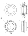
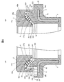
- FIG. 1A, FIG. 1B, and FIG. 1C are a front view, a rear view, and a side view of a plain bearing 1 according to an embodiment of the present invention
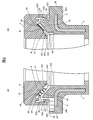
- FIG. FIG. 2 is a cross-sectional view taken along the line AA of the plain bearing 1 shown in FIG. 2A is an enlarged view of a portion B of the plain bearing 1 shown in FIG. 1D
- FIG. 2B is an enlarged view of a portion C of the plain bearing 1 shown in FIG. 3A, 3B, and 3C are a front view, a rear view, and a side view of the upper case 2
- FIG. 3D is an upper case shown in FIG. FIG.
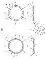
- FIG. 4 (A), 4 (B) and 4 (C) are a front view, a rear view and a side view of the lower case 3, and FIG. 4 (D) is a lower case shown in FIG. 4 (A).
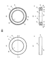
- 3 is a sectional view taken along line EE of FIG. 5A, 5B, and 5C are a front view, a back surface, and a side view of the center plate 4, and FIG. 5D is a center plate 4 shown in FIG. 5A.
- FIG. 5 (E) is an enlarged view of the G portion of the center plate 4 shown in FIG. 5 (A).
- 6 (A) and 6 (B) are diagrams for explaining a modified example of the sliding bearing 1, and correspond to FIGS. 2 (A) and 2 (B).
- FIG. 1A, 1B, and 1C are a front view, a rear view, and a side view of the plain bearing 1 according to the present embodiment
- FIG. FIG. 2 is a cross-sectional view taken along the line AA of the plain bearing 1 shown in FIG. 2A is an enlarged view of a portion B of the plain bearing 1 shown in FIG. 1D
- FIG. 2B is an enlarged view of a portion C of the plain bearing 1 shown in FIG. 1D. is there.
- the sliding bearing 1 includes a housing hole 10 for housing a strut assembly (not shown) of a strut suspension, and allows the strut assembly housed in the housing hole 10 to rotate. Supports the load applied to the strut suspension.
- the plain bearing 1 includes an upper case 2, a lower case 3 that is rotatably combined with the upper case 2, and forms an annular space 5 between the upper case 2 and the annular space 5.
- An annular center plate 4 arranged and a lubricating grease (not shown) filled in the annular space 5 are provided.
- the upper case 2 is formed of a thermoplastic resin having excellent sliding characteristics such as a polyacetal resin impregnated with a lubricating oil if necessary, and an upper mount (not shown) in a state where a strut assembly of a strut suspension is inserted. Attached to.
- FIG. 3A, 3B, and 3C are a front view, a rear view, and a side view of the upper case 2, and FIG. 3D is an upper case shown in FIG. FIG.
- the upper case 2 is formed on an annular upper case main body 21 having an insertion hole 20 for inserting a strut assembly, and an upper surface 22 of the upper case main body 21, and the sliding bearing 1 is attached to the upper mount.
- an annular groove 25 is formed on the lower surface 24 of the upper case body 21 and is rotatably combined with the lower case 3 so as to form the annular space 5
- the lower surface 23 side is opened and the upper surface 22 side is closed.
- an annular groove 25 is formed on the lower surface 24 of the upper case body 21 and is rotatably combined with the lower case 3 so as to form the annular space 5
- the lower surface 23 side is opened and the upper surface 22 side is closed.
- an annular groove 25 is formed on the lower surface 24 of the upper case body 21 and is rotatably combined with the
- the groove bottom 26 of the annular groove 25 is formed in a conical surface with the upper surface 22 side of the upper case body 21 as the bottom surface and the lower surface 23 side as the top portion, with the axis O of the insertion hole 20 as the center line,
- the groove bottom 26 is formed with a load transmission surface 27 that slides on a bearing surface 42 described later of the center plate 4.
- annular convex portion 28 protruding from the groove bottom 26 toward the lower surface 23 side of the upper case main body 21 is formed on the outer peripheral edge side of the load transmitting surface 27.
- the annular projection 28 surrounds the center plate 4 disposed in the annular groove 25, and when a load is applied to the strut suspension, the lubricating grease supplied onto the bearing surface 42 of the center plate 4 is centered. It is prevented from being pushed radially outward from the bearing surface 42 of the plate 4.
- the lower case 3 is an insert-molded product in which a steel plate 6 as a reinforcing material is embedded in a resin molded body using a thermoplastic resin such as a polyamide resin, and the strut in a state in which a strut assembly of a strut suspension is inserted.
- a coil spring (not shown) of the suspension is supported.
- FIG. 4 (A), 4 (B) and 4 (C) are a front view, a rear view and a side view of the lower case 3, and FIG. 4 (D) is a lower case shown in FIG. 4 (A).
- 3 is a sectional view taken along line EE of FIG.
- the lower case 3 is formed on a cylindrical lower case main body 31 having an insertion hole 30 for inserting a strut assembly, and an upper end portion 38 side of the lower case main body 31.
- An upper case of the upper case 2 is formed when the lower case 3 is rotatably combined with the upper case 2 and is formed on a flange portion 36 projecting radially outward from the outer peripheral surface 35 and the upper surface 32 of the flange portion 36.
- An annular protrusion 33 protruding toward the upper case 2 that is inserted into an annular groove 25 formed in the lower surface 23 of the main body 21 to form the annular space 5, and an elastic body such as urethane resin attached to the protrusion 33
- a dust seal 34 made of
- An upper spring seat (not shown), which is a spring seat at the upper end of a coil spring (not shown) of the strut suspension, is attached to the lower surface 360 of the flange portion 36 in a state where the strut assembly of the strut suspension is inserted.
- a mounting surface 331 for mounting the center plate 4 is formed on the upper surface 330 of the annular convex portion 33.
- the mounting surface 331 is a conical surface having the upper end 38 side of the lower case body 31 as the bottom surface and the lower surface 37 side as the top portion, with the axis O of the insertion hole 30 as the center line. Is formed.
- the shape of the mounting surface 331 may be any shape that matches the shape of the center plate 4 and can mount the center plate 4.
- a detent 332 for preventing rotation of the center plate 4 placed on the placement surface 331 is formed in an annular shape on the outer peripheral side of the placement surface 331.
- the rotation stopper 332 is configured by alternately arranging flat portions 3321 and convex portions 3320 protruding from the flat portion 3321 toward the upper case 2 side.
- the dust seal 34 is for preventing foreign matters such as dust from entering the annular space 5, and as shown in FIGS. 2 (A) and 2 (B), the convex portion 33 of the lower case 3 is formed as an upper portion.
- a lip 340 that closes the gap between the outer peripheral surface 333 of the convex portion 33 and the outer peripheral side inner wall 250 of the annular groove 25 when inserted into the annular groove 25 formed in the lower surface 24 of the upper case body 21 of the case 2;
- a lip 341 that closes the gap between the inner peripheral surface 334 of the portion 33 and the inner peripheral side inner wall 251 of the annular groove 25 is provided.
- the center plate 4 is formed of a thermoplastic resin having excellent sliding characteristics such as a polyolefin resin impregnated with a lubricating oil if necessary.
- the center plate 4 is fixed to the mounting surface 331 of the annular convex portion 33 formed on the upper surface 32 of the flange portion 36 of the lower case 3 and formed on the lower surface 23 of the upper case body 21 of the upper case 2. It slides with the load transmitting surface 27 of the annular groove 24. Thereby, it functions as a bearing body that realizes free rotation between the upper case 2 and the lower case 3.
- FIG. 5A, 5B, and 5C are a front view, a back surface, and a side view of the center plate 4, and FIG. 5D is a center plate 4 shown in FIG. 5A.
- FIG. 5 (E) is an enlarged view of the G portion of the center plate 4 shown in FIG. 5 (A).
- the center plate 4 includes a ring-shaped center plate body 40 into which a groove bottom 26 formed in a conical surface shape of the ring-shaped groove 25 of the upper case 2 is inserted, and a radial direction from the side surface 47 of the center plate body 40. And a plurality of convex detents 45 projecting outward.
- the upper surface 41 of the center plate body 40 is formed in a conical surface shape with the upper case 2 side as a bottom surface and the lower case 3 side as a top portion, with an axis O as a center line.
- a bearing surface 42 that slides on the load transmission surface 27 formed on the groove bottom 26 of the annular groove 25 of the case 2 is formed. Note that a burr may be provided on the inner diameter side of the center plate body 40.
- the rotation stopper 45 is formed so that the lower surface 42 of the center plate main body 40 comes into contact with the mounting surface 331 of the annular convex portion 33 formed on the upper surface 32 of the lower case main body 31 of the lower case 3.
- it When placed on the case 3, it is disposed on the flat portion 3321 of the rotation stopper 332 formed on the outer peripheral side of the placement surface 331, and is engaged with the convex portions 3320 located on both sides of the flat portion 3321.
- the center plate 4 is prevented from rotating relative to the lower case 3.
- the bearing surface 42 has a large number of recesses 46 that function as a lubricating grease reservoir. Accordingly, more lubricating grease is interposed between the bearing surface 42 of the center plate body 40 of the center plate 4 and the load transmission surface 27 formed on the groove bottom 26 of the annular groove 25 of the upper case 2. The sliding characteristics between the bearing surface 42 and the load transmission surface 27 can be improved.
- the center plate 4 is fixed to the mounting surface 331 of the annular convex portion 33 formed on the upper surface 32 of the flange portion 36 of the lower case 3, and the bearing surface 42 of the center plate 4 is the upper surface. It slides on a load transmission surface 27 formed on the groove bottom 26 of the annular groove 25 of the case 2.
- the upper case 2 and the lower case 3 are combined with each other via the center plate 4 so as to be rotatable.
- the bearing surface 42 of the center plate 4 and the load transmitting surface 27 of the upper case 2 are formed in a conical shape, and for this reason, the axial direction of the sliding bearing 1 shown in the thrust direction of the strut suspension (FIG. 1D).
- the slide bearing 1 allows the thrust and radial loads applied to the strut suspension to be applied to the strut suspension via the same load transmission surface 27 while allowing the strut assembly of the strut suspension inserted into the receiving hole 10 to rotate. And can be supported by the same bearing surface 42.
- the bearing surface 42 of the center plate 4 and the load transmission surface 27 of the upper case 2 are conical, so that the bearing surface 42 and the load transmission surface support the load applied to the strut suspension. In the state in which the two contact each other, there is no radial clearance between the bearing surface 42 and the load transmitting surface 27. Therefore, the radial play of the sliding bearing 1 can be prevented.
- the preferred inclination angle of the bearing surface 42 and the load transmission surface 27 (the angle formed by the plane perpendicular to the axis O) is 5 degrees to 20 degrees, and more preferably 10 degrees to 15 degrees.
- the inclination angle of the bearing surface 42 and the load transmission surface 27 is smaller than 5 degrees, the play between the two becomes large, and when the inclination angle is larger than 20 degrees, the sliding force between the both becomes large.
- the thrust slide bearing 1 has an annular space 5 formed by combining the upper case 2 and the lower case 3 with the groove bottom 26 of the annular groove 25 formed on the lower surface 24 of the upper case 2.
- An annular convex portion 28 that protrudes from the groove bottom 26 toward the lower case 3 side is provided so as to surround the outer peripheral side of the center plate 4 that is disposed on the center plate 4. The convex portion 28 can prevent the lubricating grease filled in the annular space 5 from being pushed radially outward from the bearing surface 42 of the center plate 4 when a load is applied to the strut suspension.
- the bearing surface 42 can be more reliably covered with the lubricating grease film, and the load applied in the thrust direction of the strut suspension can be supported for a longer period while allowing the strut assembly of the strut suspension to rotate smoothly. It becomes possible to do.
- the center plate 4 is mounted and fixed on the lower case 3, but the center plate 4 may be mounted so as to be rotatable with respect to the lower case 3. That is, like the upper surface 41 of the center plate 4, a bearing surface is also formed on the lower surface 43 of the center plate 4, and this bearing surface is formed on the upper surface 32 of the lower case body 31 of the lower case 3.
- the mounting surface 331 may be slidably contacted.
- a plurality of concave portions functioning as a lubricating grease reservoir may be formed on the bearing surface formed on the lower surface 43 of the center plate 4.
- the cross-sectional shapes of the bearing surface 42 and the load transmission surface 27 formed in a conical shape (the shape of the bearing surface 42 in the cross-section in the axis O direction of the center plate 4 and the axis O of the upper case 2).
- the shape of the load transmission surface 27 in the direction cross section is linear (see FIGS. 2A and 2B)
- the present invention is not limited to this.
- the angle of inclination of the bearing surface 42 and the load transmission surface 27 may be changed so that the cross-sectional shape thereof is a polygonal line formed by combining two or more straight lines.
- FIGS. 6 (A) and 6 (B) are diagrams for explaining a modified example of the sliding bearing 1, and correspond to FIGS. 2 (A) and 2 (B).
- the load transmission surface 27a is formed on a conical surface groove bottom 26a of an annular groove 25 provided on the lower surface 24 of the upper case body 21 of the upper case 2, and the cross-sectional shape thereof is the upper case.
- the main body 21 has an arc shape that is recessed toward the upper surface 22 side.
- the bearing surface 42a is formed on the conical surface 41a of the center plate 4, and its cross-sectional shape has a smaller diameter than the load transmission surface 27a and is an arc shape protruding toward the upper case 2 side. ing.
- the cross-sectional shapes of the bearing surface 42 and the load transmitting surface 27 formed in a conical surface are linear, so the bearing surface When the inclinations of 42 and the load transmission surface 27 coincide with each other, they are in surface contact.
- the line contact positions of the two vary. For this reason, the sliding characteristics of the sliding bearing 1 may not be stable.
- FIGS. 1 in the modification shown in FIGS.
- the cross-sectional shapes of the bearing surface 42a and the load transmission surface 27a formed in a conical surface are arc shapes (bearing surfaces) having different diameters. Since the diameter of 42a ⁇ the diameter of the load transmission surface 27a), the bearing surface 42a and the load transmission surface 27a are always in line contact with each other at a location where their tangents coincide with each other in the cross section. For this reason, it becomes possible to reduce the dispersion
- the bearing surface 42 of the center plate 4 and the load transmission surface 27 of the upper case 2 are respectively the shaft center O with the upper case 2 side as the bottom and the lower case 3 side as the top.
- it is formed in a conical surface shape as a center line, the present invention is not limited to this.
- the bearing surface 42 and the load transmission surface 27 may each be formed in a conical surface with the axis O as the center line, with the lower case 3 side as the bottom and the upper case 2 side as the top.
- the mounting surface 23 formed on the upper surface 22 of the upper case body 21 of the upper case 2 is perpendicular to the strut shaft of the strut suspension.
- the angle of the mounting surface 23 of the upper case 2 with respect to the strut shaft of the strut suspension may be appropriately determined according to the performance required for the vehicle.
- the mounting surface 23 of the upper case 2 may be inclined with respect to the strut shaft of the strut suspension.
- the upper spring seat that supports the upper end portion of the coil spring of the strut suspension is attached to the lower surface 360 of the flange portion 36 of the lower case 3.
- the lower surface 360 itself may function as an upper spring seat.
- the present invention is widely applied to a sliding bearing that supports a load to be supported, and particularly to a sliding bearing that supports a load applied to the shaft member while allowing the shaft member to rotate in various mechanisms including a strut suspension. Is possible.
Landscapes
- Engineering & Computer Science (AREA)
- General Engineering & Computer Science (AREA)
- Mechanical Engineering (AREA)
- Vehicle Body Suspensions (AREA)
- Fluid-Damping Devices (AREA)
- Sliding-Contact Bearings (AREA)
Priority Applications (3)
| Application Number | Priority Date | Filing Date | Title |
|---|---|---|---|
| US15/567,461 US10344799B2 (en) | 2015-04-28 | 2016-04-11 | Sliding bearing |
| EP16786295.2A EP3290726B1 (de) | 2015-04-28 | 2016-04-11 | Gleitlager |
| CN201680024045.XA CN107532642B (zh) | 2015-04-28 | 2016-04-11 | 滑动轴承 |
Applications Claiming Priority (2)
| Application Number | Priority Date | Filing Date | Title |
|---|---|---|---|
| JP2015092423A JP6602042B2 (ja) | 2015-04-28 | 2015-04-28 | 滑り軸受 |
| JP2015-092423 | 2015-04-28 |
Publications (1)
| Publication Number | Publication Date |
|---|---|
| WO2016175018A1 true WO2016175018A1 (ja) | 2016-11-03 |
Family
ID=57199151
Family Applications (1)
| Application Number | Title | Priority Date | Filing Date |
|---|---|---|---|
| PCT/JP2016/061716 Ceased WO2016175018A1 (ja) | 2015-04-28 | 2016-04-11 | 滑り軸受 |
Country Status (5)
| Country | Link |
|---|---|
| US (1) | US10344799B2 (de) |
| EP (1) | EP3290726B1 (de) |
| JP (1) | JP6602042B2 (de) |
| CN (1) | CN107532642B (de) |
| WO (1) | WO2016175018A1 (de) |
Families Citing this family (9)
| Publication number | Priority date | Publication date | Assignee | Title |
|---|---|---|---|---|
| JP6479444B2 (ja) * | 2014-12-03 | 2019-03-06 | オイレス工業株式会社 | 滑り軸受およびストラット式サスペンション |
| US10718375B2 (en) * | 2016-05-16 | 2020-07-21 | Roller Bearing Company Of America, Inc. | Bearing system with self-lubrication features, seals, grooves and slots for maintenance-free operation |
| JP7177074B2 (ja) * | 2017-10-06 | 2022-11-22 | オイレス工業株式会社 | 滑り軸受 |
| JP2020091031A (ja) * | 2018-12-07 | 2020-06-11 | オイレス工業株式会社 | 滑り軸受およびステアリングシャフト支持構造 |
| FR3094425B1 (fr) * | 2019-03-27 | 2021-04-23 | Poclain Hydraulics Ind | Machine hydraulique comportant un palier perfectionné |
| DE102020200586A1 (de) * | 2020-01-20 | 2021-07-22 | Aktiebolaget Skf | Aufhängungsaxiallagervorrichtung |
| FR3117938B1 (fr) * | 2020-12-17 | 2023-02-17 | Skf Svenska Kullagerfab Ab | Dispositif de butée de suspension à joint d’étanchéité |
| KR102939794B1 (ko) * | 2022-07-15 | 2026-03-16 | 주식회사 일진 | 차량용 스트럿 베어링 어셈블리 |
| US20240044363A1 (en) * | 2022-08-03 | 2024-02-08 | Schaeffler Technologies AG & Co. KG | Sliding strut bearing with polygonal annular thrust disk |
Citations (3)
| Publication number | Priority date | Publication date | Assignee | Title |
|---|---|---|---|---|
| JPH08159160A (ja) * | 1994-12-01 | 1996-06-18 | Oiles Ind Co Ltd | 合成樹脂スラスト軸受 |
| JPH10122233A (ja) * | 1996-10-21 | 1998-05-12 | Oiles Ind Co Ltd | 合成樹脂製のスラスト軸受 |
| JP2010223411A (ja) * | 2009-03-25 | 2010-10-07 | Showa Corp | ストラットダンパ |
Family Cites Families (33)
| Publication number | Priority date | Publication date | Assignee | Title |
|---|---|---|---|---|
| FR915604A (fr) * | 1944-09-11 | 1946-11-13 | Perfectionnements apportés aux paliers ou coussinets | |
| US2872256A (en) * | 1955-02-24 | 1959-02-03 | John B Thomson | Thrust bearing |
| US3989322A (en) * | 1974-04-26 | 1976-11-02 | The Heim Universal Company | Spherical bearing assembly |
| US4024616A (en) * | 1975-06-23 | 1977-05-24 | Heim Universal Corporation | Self-aligning bearing with a split inner member |
| US4395142A (en) * | 1981-03-18 | 1983-07-26 | The Torrington Company | Self-adjusting angular contact spherical bearing |
| US5106930A (en) | 1988-09-28 | 1992-04-21 | Ioptex Research Inc. | Contact lenses |
| JPH02141722U (de) * | 1989-04-28 | 1990-11-29 | ||
| US5052824A (en) * | 1990-02-08 | 1991-10-01 | Mpb Corporation | Compliant spherical bearing |
| JP2598449Y2 (ja) * | 1993-08-06 | 1999-08-09 | 株式会社ソミック石川 | ボールジョイント |
| JP2526371B2 (ja) | 1994-04-07 | 1996-08-21 | 北栄工業株式会社 | 合成樹脂スラスト軸受 |
| JP4099996B2 (ja) | 2002-01-22 | 2008-06-11 | オイレス工業株式会社 | スラスト滑り軸受 |
| US20040024076A1 (en) * | 2002-04-20 | 2004-02-05 | Davis Clyde Edward | Polymerization of various silicic acids on biological templates |
| JP4103501B2 (ja) * | 2002-08-27 | 2008-06-18 | 株式会社ジェイテクト | 円錐ころ軸受 |
| US7993061B2 (en) * | 2002-10-03 | 2011-08-09 | Oiles Corporation | Sliding bearing |
| EP1585904B1 (de) * | 2002-12-20 | 2010-10-27 | Schaeffler Technologies AG & Co. KG | Kunststoffringlager, insbesondere zur verwendung in einem macpherson-federbein |
| JP2005003185A (ja) * | 2003-06-16 | 2005-01-06 | Miki Pulley Co Ltd | 摩擦摺動体 |
| JP2006200672A (ja) * | 2005-01-21 | 2006-08-03 | Jtekt Corp | スラストころ軸受 |
| JP5561660B2 (ja) * | 2006-05-12 | 2014-07-30 | オイレス工業株式会社 | 滑り軸受 |
| JP2008175349A (ja) * | 2007-01-22 | 2008-07-31 | Jtekt Corp | ストラット軸受 |
| DE102008057590A1 (de) * | 2008-08-13 | 2010-02-18 | Schaeffler Kg | Federbeingleitlager |
| WO2010038588A1 (ja) * | 2008-10-03 | 2010-04-08 | 大豊工業株式会社 | すべり軸受とその製造方法 |
| FR2966084A1 (fr) * | 2010-10-14 | 2012-04-20 | Skf Ab | Dispositif de butee de suspension |
| FR2966086A1 (fr) * | 2010-10-14 | 2012-04-20 | Skf Ab | Dispositif de butee de suspension |
| JP5444270B2 (ja) | 2011-02-23 | 2014-03-19 | オイレス工業株式会社 | 合成樹脂製のスラスト滑り軸受 |
| JP5644636B2 (ja) * | 2011-03-30 | 2014-12-24 | オイレス工業株式会社 | スラスト滑り軸受及びこのスラスト滑り軸受とピストンロッドとの組合せ機構 |
| JP5906590B2 (ja) * | 2011-06-09 | 2016-04-20 | オイレス工業株式会社 | 合成樹脂製の滑り軸受 |
| JP2013148132A (ja) * | 2012-01-17 | 2013-08-01 | Oiles Corp | スラスト滑り軸受 |
| JP5950623B2 (ja) * | 2012-02-28 | 2016-07-13 | オイレス工業株式会社 | スラスト滑り軸受、およびスラスト滑り軸受とピストンロッドとの組合せ機構 |
| JP2014040899A (ja) * | 2012-08-23 | 2014-03-06 | Taiho Kogyo Co Ltd | テーパランド軸受 |
| JP6194586B2 (ja) * | 2013-01-29 | 2017-09-13 | オイレス工業株式会社 | 合成樹脂製の滑り軸受 |
| DE102013201965A1 (de) * | 2013-02-07 | 2014-08-07 | Schaeffler Technologies Gmbh & Co. Kg | Federbeinlager |
| JP6017340B2 (ja) * | 2013-02-15 | 2016-10-26 | オイレス工業株式会社 | 合成樹脂製の滑り軸受 |
| JP6322889B2 (ja) * | 2013-02-15 | 2018-05-16 | オイレス工業株式会社 | 合成樹脂製の滑り軸受 |
-
2015
- 2015-04-28 JP JP2015092423A patent/JP6602042B2/ja active Active
-
2016
- 2016-04-11 US US15/567,461 patent/US10344799B2/en active Active
- 2016-04-11 WO PCT/JP2016/061716 patent/WO2016175018A1/ja not_active Ceased
- 2016-04-11 CN CN201680024045.XA patent/CN107532642B/zh active Active
- 2016-04-11 EP EP16786295.2A patent/EP3290726B1/de active Active
Patent Citations (3)
| Publication number | Priority date | Publication date | Assignee | Title |
|---|---|---|---|---|
| JPH08159160A (ja) * | 1994-12-01 | 1996-06-18 | Oiles Ind Co Ltd | 合成樹脂スラスト軸受 |
| JPH10122233A (ja) * | 1996-10-21 | 1998-05-12 | Oiles Ind Co Ltd | 合成樹脂製のスラスト軸受 |
| JP2010223411A (ja) * | 2009-03-25 | 2010-10-07 | Showa Corp | ストラットダンパ |
Non-Patent Citations (1)
| Title |
|---|
| See also references of EP3290726A4 * |
Also Published As
| Publication number | Publication date |
|---|---|
| CN107532642A (zh) | 2018-01-02 |
| US20180106292A1 (en) | 2018-04-19 |
| JP6602042B2 (ja) | 2019-11-06 |
| EP3290726B1 (de) | 2021-01-27 |
| EP3290726A4 (de) | 2018-11-07 |
| US10344799B2 (en) | 2019-07-09 |
| JP2016211592A (ja) | 2016-12-15 |
| EP3290726A1 (de) | 2018-03-07 |
| CN107532642B (zh) | 2020-09-18 |
Similar Documents
| Publication | Publication Date | Title |
|---|---|---|
| JP6602042B2 (ja) | 滑り軸受 | |
| EP3404275B1 (de) | Gleitlager | |
| WO2016024472A1 (ja) | スラスト滑り軸受 | |
| JP6909789B2 (ja) | 滑り軸受 | |
| WO2016088782A1 (ja) | 滑り軸受およびストラット式サスペンション | |
| JP6917290B2 (ja) | 滑り軸受 | |
| WO2015170586A1 (ja) | スラスト滑り軸受 | |
| JP6581448B2 (ja) | 滑り軸受 | |
| WO2019069795A1 (ja) | 滑り軸受 | |
| JP2004263771A (ja) | スラスト滑り軸受 | |
| JP7288759B2 (ja) | 滑り軸受 | |
| JP6496614B2 (ja) | 滑り軸受 | |
| WO2018074254A1 (ja) | 滑り軸受 | |
| JP2017044226A (ja) | 滑り軸受 | |
| JP2008039182A (ja) | 軸受 | |
| JP4788803B2 (ja) | スラスト滑り軸受 | |
| JPWO2019138949A1 (ja) | 滑り軸受 | |
| WO2016163445A1 (ja) | 車両用スラスト軸受 | |
| JP2019138435A (ja) | 滑り軸受 | |
| JP2018123955A (ja) | 軸受 |
Legal Events
| Date | Code | Title | Description |
|---|---|---|---|
| 121 | Ep: the epo has been informed by wipo that ep was designated in this application |
Ref document number: 16786295 Country of ref document: EP Kind code of ref document: A1 |
|
| WWE | Wipo information: entry into national phase |
Ref document number: 15567461 Country of ref document: US |
|
| NENP | Non-entry into the national phase |
Ref country code: DE |