WO2016175037A1 - 装飾装置 - Google Patents
装飾装置 Download PDFInfo
- Publication number
- WO2016175037A1 WO2016175037A1 PCT/JP2016/061989 JP2016061989W WO2016175037A1 WO 2016175037 A1 WO2016175037 A1 WO 2016175037A1 JP 2016061989 W JP2016061989 W JP 2016061989W WO 2016175037 A1 WO2016175037 A1 WO 2016175037A1
- Authority
- WO
- WIPO (PCT)
- Prior art keywords
- lenticular lens
- lens sheet
- light
- smartphone
- light emission
- Prior art date
- Legal status (The legal status is an assumption and is not a legal conclusion. Google has not performed a legal analysis and makes no representation as to the accuracy of the status listed.)
- Ceased
Links
Images




Classifications
-
- G—PHYSICS
- G09—EDUCATION; CRYPTOGRAPHY; DISPLAY; ADVERTISING; SEALS
- G09F—DISPLAYING; ADVERTISING; SIGNS; LABELS OR NAME-PLATES; SEALS
- G09F13/00—Illuminated signs; Luminous advertising
- G09F13/04—Signs, boards or panels, illuminated from behind the insignia
-
- A—HUMAN NECESSITIES
- A45—HAND OR TRAVELLING ARTICLES
- A45C—PURSES; LUGGAGE; HAND CARRIED BAGS
- A45C11/00—Receptacles for purposes not provided for in groups A45C1/00-A45C9/00
-
- G—PHYSICS
- G09—EDUCATION; CRYPTOGRAPHY; DISPLAY; ADVERTISING; SEALS
- G09F—DISPLAYING; ADVERTISING; SIGNS; LABELS OR NAME-PLATES; SEALS
- G09F13/00—Illuminated signs; Luminous advertising
- G09F13/04—Signs, boards or panels, illuminated from behind the insignia
- G09F13/0413—Frames or casing structures therefor
-
- G—PHYSICS
- G09—EDUCATION; CRYPTOGRAPHY; DISPLAY; ADVERTISING; SEALS
- G09F—DISPLAYING; ADVERTISING; SIGNS; LABELS OR NAME-PLATES; SEALS
- G09F13/00—Illuminated signs; Luminous advertising
- G09F13/20—Illuminated signs; Luminous advertising with luminescent surfaces or parts
-
- G—PHYSICS
- G09—EDUCATION; CRYPTOGRAPHY; DISPLAY; ADVERTISING; SEALS
- G09F—DISPLAYING; ADVERTISING; SIGNS; LABELS OR NAME-PLATES; SEALS
- G09F19/00—Advertising or display means not otherwise provided for
- G09F19/12—Advertising or display means not otherwise provided for using special optical effects
-
- G—PHYSICS
- G09—EDUCATION; CRYPTOGRAPHY; DISPLAY; ADVERTISING; SEALS
- G09F—DISPLAYING; ADVERTISING; SIGNS; LABELS OR NAME-PLATES; SEALS
- G09F23/00—Advertising on or in specific articles, e.g. ashtrays, letter-boxes
- G09F23/0093—Advertising on or in specific articles, e.g. ashtrays, letter-boxes on phone-carried indicia
-
- H—ELECTRICITY
- H04—ELECTRIC COMMUNICATION TECHNIQUE
- H04M—TELEPHONIC COMMUNICATION
- H04M1/00—Substation equipment, e.g. for use by subscribers
- H04M1/02—Constructional features of telephone sets
- H04M1/11—Supports for sets, e.g. incorporating armrests
-
- A—HUMAN NECESSITIES
- A45—HAND OR TRAVELLING ARTICLES
- A45C—PURSES; LUGGAGE; HAND CARRIED BAGS
- A45C11/00—Receptacles for purposes not provided for in groups A45C1/00-A45C9/00
- A45C11/002—Receptacles for purposes not provided for in groups A45C1/00-A45C9/00 for storing portable handheld communication devices, e.g. pagers or smart phones
-
- G—PHYSICS
- G09—EDUCATION; CRYPTOGRAPHY; DISPLAY; ADVERTISING; SEALS
- G09F—DISPLAYING; ADVERTISING; SIGNS; LABELS OR NAME-PLATES; SEALS
- G09F13/00—Illuminated signs; Luminous advertising
- G09F13/20—Illuminated signs; Luminous advertising with luminescent surfaces or parts
- G09F13/22—Illuminated signs; Luminous advertising with luminescent surfaces or parts electroluminescent
- G09F2013/222—Illuminated signs; Luminous advertising with luminescent surfaces or parts electroluminescent with LEDs
Definitions
- the present invention relates to a decoration device for decorating the appearance of a smartphone or the like.
- Decorative covers for decorating the appearance of smartphones and tablet computers are known.
- the decorative cover described in Patent Document 1 is provided on an engagement portion that engages with the outer peripheral edge of a smartphone, a cover portion that is provided integrally with the engagement portion, and a surface of the cover portion. And a decorative part having a shape.
- This decorative cover is detachably attached to the smartphone.
- the cover portion is formed by laminating sheet materials of different colors, and is decorated by forming a notch in the sheet material on the upper surface side to expose the sheet material on the lower surface side.
- the element that decorates the smartphone is a decorative part, a cutout formed in the cover part, etc., and a finger or the like may be caught, which may hinder the operation.
- small light sources such as LEDs (Light Emitting Diodes) have been widely used as decorative elements.
- light sources such as LEDs have a narrow range of light emission, and a large number of light sources are required to obtain highly decorative illumination light.
- the applicant is studying to create a decoration device that is safe and does not hinder the operation and can provide highly decorative illumination light with a small number of light sources and has improved decoration.
- An object of the present invention is to provide a decoration device that has a decorative property improved by a safe and highly decorative illumination light.
- the decoration device of the present invention is a decoration device that decorates an operating device, and includes a lenticular lens sheet, a light source, and a drive unit.
- a lenticular lens sheet a plurality of cylindrical lenses having a convex shape are arranged, and a flat surface is formed on the side opposite to the convex shape.
- the light source is arranged on the flat surface side.
- a drive part changes the light emission state of a light source according to the operating state of an operating device, or the information which an operating device has.
- one lenticular lens sheet is inclined with respect to other lenticular lens sheets.
- One lenticular lens sheet is preferably provided so as to be slidable with respect to another lenticular lens sheet.
- the drive unit changes the light emission pattern of the light source according to the operating state of the operating device or information held by the operating device.
- One lenticular lens sheet is preferably provided with an image forming layer on which a pattern is formed on the flat surface side.
- the light source is arranged on the flat surface side of the lenticular lens sheet in which a plurality of cylindrical lenses are arranged, and the light emitting state is changed according to the operating state of the operating device or information held by the operating device.
- the decorativeness can be improved by illumination light that is safe and has high decorativeness without obstructing.
- FIGS. As an example of the decorative device of the present invention, a decorative cover 10 is shown in FIGS. As shown in FIG. 1, the decorative cover 10 is attached to a smartphone 11 as an operating device and decorates the appearance of the smartphone 11.
- the smartphone 11 has a display input unit 12 on the surface 11A.
- a predetermined instruction is given to the control unit 15 (see FIG. 4) by operating the display input unit 12 with a finger or the like.
- a known touch panel display is used as the display input unit 12.
- the smartphone 11 is provided with a camera module 13 on the back surface 11B side to which the decorative cover 10 is attached.
- the camera module 13 is used to shoot still images and moving images. Still images and moving images shot by the camera module 13 are displayed on the display input unit 12.
- the smartphone 11 is provided with a power switch 14 and the like.
- the smartphone 11 includes a control unit 15, a communication unit 16, a contact point 17 and the like.
- the control unit 15 controls each unit of the smartphone 11 and executes various processes corresponding to the input instructions.
- the communication unit 16 communicates with a telephone company base station.
- the control unit 15 communicates with the base station via the communication unit 16 in response to an input from the display input unit 12 or the like. And it can talk with another telephone via the microphone and speaker (not shown) which were incorporated in the smart phone 11.
- the control unit 15 is connected to the Internet via the communication unit 16, thereby displaying a web page on the display input unit 12, sending / receiving mails, and the like.
- the contact 17 electrically connects the control unit 15 and the decorative cover 10 by contacting a contact 23 of the decorative cover 10 described later.
- the decorative cover 10 includes a lenticular lens sheet 21, an outer frame 22, contacts 23, a plurality of LED chips 24, and a substrate 25.
- the outer frame 22 is a rectangular frame that is fitted on the outer peripheral edge of the smartphone 11.
- the outer frame 22 has a notch 22a that exposes the power switch 14.
- the lenticular lens sheet 21 is provided integrally with the outer frame 22.
- the lenticular lens sheet 21 covers the back surface 11 ⁇ / b> B of the smartphone 11 when the outer frame 22 is fitted on the outer peripheral edge of the smartphone 11.
- the lenticular lens sheet 21 is composed of a plurality of cylindrical lenses 26.
- Each cylindrical lens 26 has a semi-cylindrical convex shape 26A, and the side opposite to the convex shape 26A is flat.
- Each cylindrical lens 26 extends in the Y direction and is arranged in parallel with the adjacent cylindrical lens 26. That is, the cylindrical lenses 26 are arranged at a constant pitch in the X direction orthogonal to the Y direction.
- the lenticular lens sheet 21 has a flat surface 21A on the side opposite to the convex shape 26A.
- a transparent resin material such as PET (polyethylene terephthalate), PP (polypropylene), PETG (glycol-modified polyethylene terephthalate), polycarbonate, acrylic, acrylate resin or the like is used.
- the substrate 25 is attached to a position facing the flat surface 21 ⁇ / b> A of the lenticular lens sheet 21 inside the outer frame 22.
- a plurality of LED chips 24 are provided on the substrate 25 as a light source of the decorative cover 10.
- the LED chip 24 is arranged on the flat surface 21 ⁇ / b> A side of the lenticular lens sheet 21 in parallel with the longitudinal direction (Y direction) of the cylindrical lens 26.
- the LED chip 24 is controlled to emit light by a drive unit 27 provided on the substrate 25.
- the drive unit 27 is connected to the control unit 15 of the smartphone 11 via the contact points 17 and 23.
- the drive unit 27 changes the light emission state of the LED chip 24 in conjunction with the operation state of the smartphone 11 by the control unit 15.
- This light emission state includes light emission and non-light emission timings, light emission patterns, and the like.
- the LED chip 24 As the LED chip 24, a red LED, a green LED, a blue LED, a white LED, or the like is used.
- the plurality of LED chips 24 provided on the substrate 25 may all be the same color, or may be a combination of a plurality of colors.
- the operating state of the smartphone 11 includes a call state in which a call is made with another telephone, a net browsing state in which a web page is displayed on the display input unit 12 by connecting to the Internet, a mail transmission / reception state in which mail is transmitted / received, and the like. .
- the control unit 15 outputs a light emission control signal that causes the LED chip 24 to emit light.
- the light emission control signal controls a light emission pattern for causing each of the plurality of LED chips 24 to emit light. This light emission pattern is preferably different for each operating state.
- the driving unit 27 receives a light emission control signal from the smartphone 11 via the contacts 17 and 23.
- the drive unit 27 sets each LED chip 24 to a light emitting state or a non-light emitting state based on the received light emission control signal.
- FIG. 5 shows a state where all the LED chips 24 emit light.
- the light emitted from each LED chip 24 passes through the lenticular lens sheet 21, the light is diffused in the arrangement direction (X direction) of the cylindrical lenses 26 to become linear light.
- the decorative cover 10 line-shaped light is generated for each LED chip 24 arranged in parallel with the longitudinal direction (Y direction) of the cylindrical lens 26, so that the decorative cover 10 is striped over substantially the entire surface of the lenticular lens sheet 21.
- highly decorative illumination light can be obtained.
- each LED chip 24 is made into a light emission state or a non-light emission state based on the light emission control signal according to the operation state of the smart phone 11, a user changes the operation state of the smart phone 11 with the light emission pattern of illumination light. Can be recognized.
- the LED chip 24, the substrate 25, and the like are covered with the lenticular lens sheet 21 and the outer frame 22, and a finger or the like is not caught. it can. Further, when the smartphone 11 is activated, the decorative cover 10 causes each LED chip 24 to be in a light emitting state or a non-light emitting state depending on the operating state. And since linear light is emitted via the lenticular lens sheet 21, illumination light with high decoration property is obtained, and the decoration property of the smartphone 11 is improved.
- the light emission pattern of each LED chip 24 by the light emission control signal is changed according to the operating state of the smart phone 11, you may change a light emission pattern according to the information which the smart phone 11 has.
- the light emission pattern may be changed in accordance with incoming information on incoming calls or mails (whether there is an incoming call), remaining battery information, current time, weather information such as weather and temperature, and the like.
- the decorative cover 30 of the second embodiment includes a first lenticular lens sheet 31 and a second lenticular lens sheet 32.
- the first lenticular lens sheet 31 and the second lenticular lens sheet 32 are laminated. Similar to the lenticular lens sheet 21 of the first embodiment, the first lenticular lens sheet 31 is provided integrally with the outer frame 22.
- the first lenticular lens sheet 31 covers the back surface 11 ⁇ / b> B of the smartphone 11 when the outer frame 22 is fitted on the outer peripheral edge of the smartphone 11.
- the first lenticular lens sheet 31 is formed with an opening 31 ⁇ / b> A that exposes the camera module 13.
- the second lenticular lens sheet 32 has the same configuration as the first lenticular lens sheet 31 except that the second lenticular lens sheet 32 is smaller than the first lenticular lens sheet 31, and is attached between the first lenticular lens sheet 31 and the substrate 25. ing.
- the first lenticular lens sheet 31 and the second lenticular lens sheet 32 are bonded using a method such as adhesion or adhesion.
- a bonding agent adheresive or adhesive
- illumination light can be observed through the first and second lenticular lens sheets 31 and 32.
- a material having optical transparency is used.
- the first and second lenticular lens sheets 31 and 32 are arranged non-parallel to each other. That is, the longitudinal direction (Y2 direction) of the cylindrical lens 26 of the second lenticular lens sheet 32 has an inclination ⁇ with respect to the longitudinal direction (Y1 direction) of the cylindrical lens 26 of the first lenticular lens sheet 31.
- the two lenticular lens sheet 32 is inclined with respect to the first lenticular lens sheet 31. Thereby, the illumination light emitted from the LED chip 24 is diffused in different directions when passing through the first lenticular lens sheet 31 and when passing through the second lenticular lens sheet 32.
- each LED chip 24 is arranged in the arrangement direction (X1 direction) of the cylindrical lens 26 of the first lenticular lens sheet 31 and the arrangement direction of the cylindrical lens 26 of the second lenticular lens sheet 32.
- Each of the light beams diffuses in the (X2 direction) and crosses each other to form line-shaped light. That is, moire is generated in the illumination light according to the inclination ⁇ , and a special visual effect is obtained.
- illumination light with higher decorativeness can be obtained.
- the second lenticular lens sheet 32 is joined and fixed to the first lenticular lens sheet 31.
- the present invention is not limited to this, and the second lenticular lens sheet 32 is rotatably provided.
- a rotation mechanism (not shown) for changing the longitudinal inclination of the cylindrical lens 26 by rotating the second lenticular lens sheet 32 with respect to the first lenticular lens sheet 31 may be provided.
- the drive unit 27 may operate the rotation mechanism in accordance with the control signal of the smartphone 11 and rotate the second lenticular lens sheet 32 in accordance with the operation state of the smartphone 11 or information held by the smartphone 11.
- the lenticular lens sheet is transparent, but an image may be formed on the flat surface side of the lenticular lens sheet.
- the decorative cover 40 of the third embodiment shown in FIGS. 9 and 10 is provided with an image forming layer 41 integrally with the lenticular lens sheet 21.
- the decorative cover 40 has the same configuration as the decorative cover 10 of the first embodiment except that the decorative cover 40 includes the image forming layer 41.
- the image forming layer 41 is provided on the flat surface 21A side of the lenticular lens sheet 21.
- the image forming layer 41 is formed by printing or transferring an image directly on the flat surface 21A.
- the material of the image forming layer 41 may be any material that can be in close contact with the flat surface 21A of the lenticular lens sheet 21 and has light transmittance, and a known paint or the like is used.
- a pattern is formed on the image forming layer 41.
- a twill pattern formed when carbon fibers are twilled is formed on the image forming layer 41.
- the LED chip 24 emits light
- line-shaped light is emitted through the lenticular lens sheet 21, and the pattern formed on the image forming layer 41 appears in the illumination light.
- illumination light with higher decorativeness can be obtained.
- the image forming layer 41 is directly formed on the flat surface 21A of the lenticular lens sheet 21, but the image forming layer 41 is formed on an image forming medium (not shown) that is a transparent resin sheet.
- the image forming medium may be bonded to the lenticular lens sheet 21.
- a bonding agent adheresive or adhesive
- FIG. 11 shows an example in which the decoration device of the present invention is applied to the lighting device 50.
- the illumination device 50 includes first and second lenticular lens sheets 51 and 52, a pedestal 53, a plurality of light sources 54, and a drive unit 55 that changes the light emission state of the light sources 54.
- the first lenticular lens sheet 51 is provided with the same image forming layer 41 as in the third embodiment.
- the lighting device 50 is attached to, for example, a desktop computer as an operating device.
- the drive unit 55 is electrically connected to the control unit of the computer.
- the drive unit 55 changes the light emission state of the light source 54 in conjunction with the operating state of the computer.
- This light emission state includes light emission and non-light emission timings, light emission patterns, and the like.
- the first lenticular lens sheet 51 is curved in a cylindrical shape with the convex shape 26A of the cylindrical lens 26 as the outer peripheral surface side.
- the bending direction is a direction orthogonal to the longitudinal direction (Y1 direction) of the cylindrical lens 26.
- the first lenticular lens sheet 51 is supported by the pedestal 53.
- the second lenticular lens sheet 52 is curved in a cylindrical shape so that the inner peripheral surface surrounds the outer peripheral surface of the first lenticular lens sheet 51.
- the longitudinal directions of the cylindrical lenses 26 are orthogonal to each other.
- the longitudinal direction (Y2 direction) of the cylindrical lens 26 of the second lenticular lens sheet 32 is orthogonal to the longitudinal direction (Y1 direction) of the cylindrical lens 26 of the first lenticular lens sheet 51.
- Each light source 54 is made of an LED, for example, and is supported by a support (not shown). Each light source 54 is disposed in a cylindrical internal space formed by the first lenticular lens sheet 51 at a predetermined interval in parallel with the longitudinal direction of the cylindrical lens 26 of the first lenticular lens sheet 51.
- the light source 54 a red LED, a green LED, a blue LED, a white LED, or the like is used.
- the plurality of light sources 54 provided in the illumination device 50 may all be the same color, or may be a combination of a plurality of colors.
- the second lenticular lens sheet 52 is slidable with respect to the first lenticular lens sheet 51.
- the first lenticular lens sheet 51 When the light emitted from each light source 54 passes through the first lenticular lens sheet 51, it is diffused in the arrangement direction (Y2 direction) of the cylindrical lenses 26 to become ring-shaped light. Further, when the light emitted from each light source 54 passes through the second lenticular lens sheet 52, it is diffused in the longitudinal direction (Y1 direction) of the cylindrical lens 26 to become linear light.
- the light emitted from the light source 54 is diffused in the direction orthogonal to the longitudinal direction of the cylindrical lens 26 when passing through the first lenticular lens sheet 51 and the second lenticular lens sheet 52. High-quality illumination light can be obtained.
- the second lenticular lens sheet 52 is slidable with respect to the first lenticular lens sheet 51, the user can change the direction in which light is diffused by manually sliding the second lenticular lens sheet 52. it can.
- the second lenticular lens sheet 52 is manually slidable with respect to the first lenticular lens sheet 51, but the present invention is not limited to this, and the second lenticular lens sheet 52 is electrically moved.
- a moving mechanism (not shown) may be provided. In this case, it is preferable that the drive unit 55 operates the moving mechanism according to the control signal of the computer and slides the second lenticular lens sheet 52 according to the operating state of the computer.
- FIG. 12 shows an example in which the decoration device 60 of the present invention is applied to an interior product of an automobile 61 as an operating device.
- the decoration device 60 is attached so as to be embedded in a part of the interior product.
- the decoration device 60 includes a lenticular lens sheet 21 similar to the decoration cover 10 of the first embodiment, a plurality of LED chips 24, and a substrate 25.
- the lenticular lens sheet 21 is integrally provided with the same image forming layer 41 as in the third embodiment.
- the decoration device 60 is attached to the steering wheel 62, the door panel 63, the dashboard 64, etc. of the motor vehicle 61, for example. Since the decoration device 60 has flexibility, it is affixed in a state of being curved in accordance with the curved surface of the affixed portion.
- the drive unit 27 provided on the substrate 25 is electrically connected to the control unit of the automobile 61 via a wiring (not shown), and outputs a light emission control signal for causing the LED chip 24 to emit light when the engine is started, for example. To do.
- the driving unit 27 changes the light emission state of each LED chip 24 based on the light emission control signal.
- This light emission state includes light emission and non-light emission timings, light emission patterns, and the like.
- the light emission state of each LED chip 24 is changed by the light emission control signal transmitted from the control unit of the automobile 61.
- the car navigation device attached to the automobile 61 emits light.
- the timing of non-light emission, the light emission pattern, and the like can be set, and the light emission control signal may be transmitted to the drive unit 27 based on this setting.
- the light emission pattern or the like may be set from a communication terminal such as a smartphone or a tablet computer.
- the light emission pattern set for the drive unit 27 from the car navigation device or the communication terminal for example, the light emission pattern is changed according to the current time, weather information such as weather and temperature, music of the car stereo of the car 61, and the like. Also good.
- an LED is used as a light source, but a light source other than an LED may be used. Further, the color of the light source may be variable, and the color of the light source may be changed based on the light emission control signal.
- smartphones, automobiles, and lighting devices are cited as operating devices to which the decoration device of the present invention is applied. It is also possible to apply the device.
- Decorative cover (decoration device) 11 Smartphone (operating device) 11A Front surface 11B Back surface 12 Display input unit 13 Camera module 14 Power switch 15 Control unit 16 Communication unit 17, 23 Contact 21 Lenticular lens sheet 21A Flat surface 22 Outer frame 22a Notch 24 LED chip 25 Substrate 26 Cylindrical lens 26A Convex 27 Drive Portions 31 and 51 First lenticular lens sheet 31A Openings 32 and 52 Second lenticular lens sheet 41 Image forming layer 50 Illuminating device (decorating device) 53 pedestal 54 light source 55 drive unit 60 decoration device 61 automobile (operating device) 62 Steering wheel 63 Door panel 64 Dashboard
Landscapes
- Engineering & Computer Science (AREA)
- Physics & Mathematics (AREA)
- General Physics & Mathematics (AREA)
- Theoretical Computer Science (AREA)
- Signal Processing (AREA)
- Business, Economics & Management (AREA)
- Accounting & Taxation (AREA)
- Marketing (AREA)
- Illuminated Signs And Luminous Advertising (AREA)
- Telephone Set Structure (AREA)
- Circuit Arrangement For Electric Light Sources In General (AREA)
- Arrangements Of Lighting Devices For Vehicle Interiors, Mounting And Supporting Thereof, Circuits Therefore (AREA)
Abstract
安全で、かつ装飾性の高い照明光により装飾性を向上させた装飾装置を提供する。 装飾カバー(10)は、レンチキュラレンズシート(21)と、外枠(22)と、接点(23)と、複数のLEDチップ(24)とを備える。外枠(22)は、スマートフォン(11)の外周縁に外嵌される。レンチキュラレンズシート(21)は、外枠(22)と一体に設けられ、スマートフォン(11)の裏面(11B)を覆う。LEDチップ(24)は、レンチキュラレンズシート(21)の平坦面(21A)側に、シリンドリカルレンズ(26)の長手方向と平行に複数配されている。複数のLEDチップ(24)は、駆動部(27)によって発光状態が変更される。駆動部(27)は、接点(17)、(23)を介してスマートフォン(11)の制御部(15)と接続され、制御部(15)によるスマートフォン(11)の作動状態に連動してLEDチップ(24)の発光状態を変更する。
Description
本発明は、スマートフォン等の外観を装飾する装飾装置に関する。
スマートフォンやタブレット型コンピュータ等の外観を装飾するための装飾カバーが知られている。例えば、特許文献1記載の装飾カバーは、スマートフォンの外周縁に係合する係合部と、係合部と一体に設けられたカバー部と、カバー部の表面に設けられ、絵柄や文字等の形状をした装飾部品とを有している。この装飾カバーは、スマートフォンに対して着脱自在に取り付けられる。また、カバー部は、色の異なるシート材を積層して形成され、上面側のシート材に切り欠きを形成して下面側のシート材を露呈させることで装飾している。
上記特許文献1記載の装飾カバーでは、スマートフォンを装飾する要素としては、装飾部品や、カバー部に形成された切り欠き等であり、指等が引っ掛かり、操作の妨げになる場合がある。また、最近では、装飾要素として、LED(Light Emitting Diode)等の小型の光源が広く用いられている。しかしながら、LED等の光源は、発光する範囲が狭く、装飾性の高い照明光を得るためには、多数の光源を必要としていた。
そこで、出願人は、操作の妨げにならずに安全で、かつ少ない光源で装飾性の高い照明光が得られ、装飾性を向上させた装飾装置を作成することを検討している。
本発明は、安全で、かつ装飾性の高い照明光により装飾性を向上させた装飾装置を提供することを目的とする。
本発明の装飾装置は、作動機器を装飾する装飾装置であって、レンチキュラレンズシートと、光源と、駆動部とを備える。レンチキュラレンズシートは、凸形状を有するシリンドリカルレンズが複数配列され、凸形状とは反対側に平坦面が形成されている。光源は、平坦面側に配されている。駆動部は、作動機器の作動状態又は作動機器が有する情報に応じて、光源の発光状態を変化させる
光源を複数有し、複数の光源は、シリンドリカルレンズの長手方向と平行に配列されていることが好ましい。レンチキュラレンズシートを複数有し、複数のレンチキュラレンズシートは積層されていることが好ましい。
1つのレンチキュラレンズシートは、他のレンチキュラレンズシートに対して傾斜していることが好ましい。1つのレンチキュラレンズシートは、他のレンチキュラレンズシートに対してスライド自在に設けられていることが好ましい。
駆動部は、作動機器の作動状態又は作動機器が有する情報に応じて、光源の発光パターンを変更することが好ましい。1つのレンチキュラレンズシートには、平坦面側に、絵柄が形成された画像形成層が設けられていることが好ましい。
本発明によれば、シリンドリカルレンズが複数配列されたレンチキュラレンズシートの平坦面側に光源を配し、作動機器の作動状態又は作動機器が有する情報に応じて、発光状態を変化させるので、操作の妨げにならずに安全で、かつ装飾性の高い照明光により装飾性を向上させることができる。
[第1実施形態]
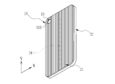
本発明の装飾装置の一例として、図1~図3に装飾カバー10を示す。図1に示すように、装飾カバー10は、作動機器としてのスマートフォン11に取り付けられて、スマートフォン11の外観を装飾するものである。スマートフォン11は、表面11Aに表示入力部12を有する。スマートフォン11は、表示入力部12が指等で操作されることで所定の指示が制御部15(図4参照)に与えられる。表示入力部12としては、公知のタッチパネルディスプレイが用いられる。
本発明の装飾装置の一例として、図1~図3に装飾カバー10を示す。図1に示すように、装飾カバー10は、作動機器としてのスマートフォン11に取り付けられて、スマートフォン11の外観を装飾するものである。スマートフォン11は、表面11Aに表示入力部12を有する。スマートフォン11は、表示入力部12が指等で操作されることで所定の指示が制御部15(図4参照)に与えられる。表示入力部12としては、公知のタッチパネルディスプレイが用いられる。
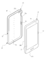
図2及び図3に示すように、スマートフォン11には、装飾カバー10が取り付けられる裏面11B側にカメラモジュール13が設けられている。このカメラモジュール13を用いて静止画や動画の撮影が行われる。カメラモジュール13で撮影された静止画や動画は、表示入力部12に表示される。また、スマートフォン11には、電源スイッチ14等が設けられている。
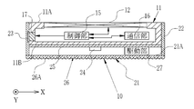
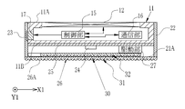
図4に示すように、スマートフォン11は、制御部15、通信部16、接点17等を備える。制御部15は、表示入力部12等の操作に応答して、スマートフォン11の各部を統括的に制御し、入力された指示に対応する各種処理を実行する。通信部16は、電話会社の基地局と通信を行う。
制御部15は、表示入力部12等の入力に応じて、通信部16を介し、基地局と通信を行う。そして、スマートフォン11に内蔵されたマイク及びスピーカ(図示せず)を介して、他の電話と通話を行うことができる。また、制御部15は、通信部16を介し、インターネットと接続することにより、ウェブページの表示入力部12への表示や、メールの送受信等を行う。接点17は、後述する装飾カバー10の接点23と接触することにより、制御部15と装飾カバー10とを電気的に接続する。
図3に示すように、装飾カバー10は、レンチキュラレンズシート21と、外枠22と、接点23と、複数のLEDチップ24と、基板25とを備える。外枠22は、スマートフォン11の外周縁に外嵌される長方形の枠体である。外枠22には、電源スイッチ14を露呈させる切り欠き22aが形成されている。
レンチキュラレンズシート21は、外枠22と一体に設けられている。レンチキュラレンズシート21は、外枠22がスマートフォン11の外周縁に外嵌された場合に、スマートフォン11の裏面11Bを覆う。
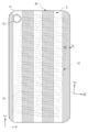
レンチキュラレンズシート21は、複数のシリンドリカルレンズ26により構成されている。各シリンドリカルレンズ26は、半円柱形の凸形状26Aを有し、この凸形状26Aとは反対側は平坦状である。各シリンドリカルレンズ26は、Y方向に延伸しており、隣接するシリンドリカルレンズ26と平行に配置されている。すなわち、シリンドリカルレンズ26は、Y方向と直交するX方向に一定のピッチで配置されている。レンチキュラレンズシート21は、凸形状26Aとは反対側に平坦面21Aを有する。
レンチキュラレンズシート21の材料としては、PET(ポリエチレンテレフタレート)、PP(ポリプロピレン)、PETG(グリコール変性ポリエチレンテレフタレート)、ポリカーボネート、アクリル、アクリレート系樹脂等の透明な樹脂材料が用いられる。
基板25は、外枠22の内部で、レンチキュラレンズシート21の平坦面21Aと対面する位置に取り付けられている。LEDチップ24は、装飾カバー10の光源として、基板25上に複数設けられている。LEDチップ24は、レンチキュラレンズシート21の平坦面21A側に、シリンドリカルレンズ26の長手方向(Y方向)と平行に配列されている。LEDチップ24は、基板25に設けられた駆動部27によって発光制御される。駆動部27は、接点17、23を介してスマートフォン11の制御部15と接続される。駆動部27は、制御部15によるスマートフォン11の作動状態に連動してLEDチップ24の発光状態を変化させる。この発光状態には、発光及び非発光のタイミングや、発光パターン等が含まれる。
LEDチップ24としては、赤色LED、緑色LED、青色LED、白色LED等が用いられる。基板25に設ける複数のLEDチップ24は、全て同一色であっても良いが、複数色を組み合わせたものであっても良い。
スマートフォン11に装飾カバー10を取り付ける場合、例えば、スマートフォン11に専用のアプリケーションソフトをインストールする。このアプリケーションソフトを実行することにより、スマートフォン11は、その作動状態に応じて接点17から制御信号を出力する。
スマートフォン11の作動状態には、他の電話機との通話を行う通話状態、インターネットと接続してウェブページ等を表示入力部12に表示するネット閲覧状態、メールの送受信を行うメール送受信状態等がある。これらの各状態において、制御部15は、LEDチップ24を発光させる発光制御信号を出力する。この発光制御信号は、複数のLEDチップ24のそれぞれを発光させる発光パターンを制御するものである。この発光パターンは、作動状態ごとに異なることが好ましい。
駆動部27は、接点17、23を介してスマートフォン11から発光制御信号を受信する。駆動部27は、受信した発光制御信号に基づいて、各LEDチップ24を発光状態または非発光状態とする。
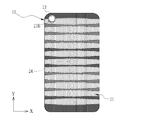
図5は、全てのLEDチップ24が発光した状態を示している。各LEDチップ24から射出された光は、レンチキュラレンズシート21を通過する際に、シリンドリカルレンズ26の配列方向(X方向)に拡散してライン状の光となる。装飾カバー10では、シリンドリカルレンズ26の長手方向(Y方向)と平行に配されたLEDチップ24ごとにライン状の光が生成されるので、レンチキュラレンズシート21の略全面に渡って縞状となった、装飾性の高い照明光が得られる。
また、各LEDチップ24が、スマートフォン11の作動状態に応じた発光制御信号に基づいて、発光状態または非発光状態とされるので、ユーザは、照明光の発光パターンにより、スマートフォン11の作動状態を認識することができる。
以上のように、本発明の装飾カバー10では、LEDチップ24、及び基板25等がレンチキュラレンズシート21、外枠22で覆われ、指等が引っ掛かることが無いため、安全に操作を行うことができる。さらに、装飾カバー10は、スマートフォン11が作動した場合に、その作動状態に応じて、各LEDチップ24が発光状態または非発光状態とされる。そして、レンチキュラレンズシート21を介してライン状の光が発せられるので、装飾性の高い照明光が得られ、スマートフォン11の装飾性が向上する。
なお、上記実施形態では、スマートフォン11の作動状態に応じて発光制御信号による各LEDチップ24の発光パターンを変更しているが、スマートフォン11が有する情報に応じて発光パターンを変更しても良い。例えば、電話やメールの着信情報(着信の有無)や、バッテリの残量情報、現在時刻、天気や気温等の気象情報等に応じて発光パターンを変更しても良い。
[第2実施形態]
上記第1実施形態では、装飾カバー10にレンチキュラレンズシート21を1枚だけ設けているが、本発明はこれに限定するものではなく、複数枚のレンチキュラレンズシートを積層することも好ましい。
上記第1実施形態では、装飾カバー10にレンチキュラレンズシート21を1枚だけ設けているが、本発明はこれに限定するものではなく、複数枚のレンチキュラレンズシートを積層することも好ましい。
図6及び図7において、第2実施形態の装飾カバー30は、第1レンチキュラレンズシート31、第2レンチキュラレンズシート32を有する。第1レンチキュラレンズシート31及び第2レンチキュラレンズシート32は積層されている。第1レンチキュラレンズシート31は、第1実施形態のレンチキュラレンズシート21と同様に、外枠22と一体に設けられる。第1レンチキュラレンズシート31は、外枠22がスマートフォン11の外周縁に外嵌された場合、スマートフォン11の裏面11Bを覆う。また、第1レンチキュラレンズシート31には、カメラモジュール13を露呈させる開口部31Aが形成されている。
第2レンチキュラレンズシート32は、第1レンチキュラレンズシート31よりも小さいこと以外は、第1レンチキュラレンズシート31と同様の構成であり、第1レンチキュラレンズシート31と、基板25との間に取り付けられている。
第1レンチキュラレンズシート31と、第2レンチキュラレンズシート32とは、接着や粘着等の方法を用いて接合されている。第1レンチキュラレンズシート31と、第2レンチキュラレンズシート32とを接合させる接合剤(接着剤や粘着剤)としては、第1及び第2レンチキュラレンズシート31、32を介して照明光が観察可能なように、光透過性を有する材料が用いられる。
第1及び第2レンチキュラレンズシート31、32は、互いに非平行に配されている。すなわち、第1レンチキュラレンズシート31のシリンドリカルレンズ26の長手方向(Y1方向)に対して第2レンチキュラレンズシート32のシリンドリカルレンズ26の長手方向(Y2方向)は、傾きαを有しており、第2レンチキュラレンズシート32は、第1レンチキュラレンズシート31に対して傾斜している。これにより、LEDチップ24から発する照明光は、第1レンチキュラレンズシート31を通過する際と、第2レンチキュラレンズシート32を通過する際とで、それぞれ異なる方向に拡散する。
図8に示すように、各LEDチップ24から射出された光は、第1レンチキュラレンズシート31のシリンドリカルレンズ26の配列方向(X1方向)と、第2レンチキュラレンズシート32のシリンドリカルレンズ26の配列方向(X2方向)とにそれぞれ拡散して、互いに交差したライン状の光となる。すなわち、照明光には、傾きαに応じてモアレが生じ、特殊な視覚効果が得られる。このように、本実施形態では、さらに装飾性の高い照明光が得られる。
なお、上記第2実施形態では、第1レンチキュラレンズシート31に対して第2レンチキュラレンズシート32を接合して固定させているが、これに限らず、第2レンチキュラレンズシート32を回転自在に設け、かつ第2レンチキュラレンズシート32を第1レンチキュラレンズシート31に対して回転させることにより、シリンドリカルレンズ26の長手方向の傾きを変える回転機構(図示せず)を設けてもよい。
この場合、駆動部27は、スマートフォン11の制御信号に応じて回転機構を作動させ、スマートフォン11の作動状態や、スマートフォン11が有する情報に応じて第2レンチキュラレンズシート32を回転させてもよい。
[第3実施形態]
上記第1及び第2実施形態では、レンチキュラレンズシートは透明であるが、レンチキュラレンズシートの平坦面側に画像を形成しても良い。
上記第1及び第2実施形態では、レンチキュラレンズシートは透明であるが、レンチキュラレンズシートの平坦面側に画像を形成しても良い。
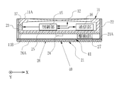
図9及び図10に示す第3実施形態の装飾カバー40は、レンチキュラレンズシート21と一体に画像形成層41が設けられている。装飾カバー40は、画像形成層41を有すること以外は、第1実施形態の装飾カバー10と同一の構成である。
画像形成層41は、レンチキュラレンズシート21の平坦面21A側に設けられている。画像形成層41は、平坦面21Aに画像を直接印刷または転写することにより形成されている。この場合、画像形成層41の材料としては、レンチキュラレンズシート21の平坦面21Aに密着可能で、かつ光透過性を有する材料であればよく、公知の塗料等が用いられる。
画像形成層41には、絵柄が形成されている。本実施形態では、絵柄として、カーボン繊維を綾織した場合に生じる綾織パターンが画像形成層41に形成されている。LEDチップ24が発光すると、レンチキュラレンズシート21を介してライン状の光が発せられ、画像形成層41に形成された絵柄が、照明光中に現れる。このように、本実施形態では、さらに装飾性の高い照明光が得られる。
なお、本実施形態では、レンチキュラレンズシート21の平坦面21Aに画像形成層41を直接形成しているが、画像形成層41を、透明な樹脂シートである画像形成媒体(図示せず)に形成したうえで、この画像形成媒体をレンチキュラレンズシート21に接合しても良い。この場合、レンチキュラレンズシート21と画像形成媒体とを接合させる接合剤(接着剤や粘着剤)としては、レンチキュラレンズシート21を介して画像形成層41が観察可能なように、透明性を有する材料が用いられる。
[第4実施形態]
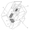
次に、図11は、本発明の装飾装置を照明装置50に適用した例を示す。照明装置50は、第1及び第2レンチキュラレンズシート51、52と、台座53と、複数の光源54と、光源54の発光状態を変化させる駆動部55とを備える。レンチキュラレンズシート51、52のうち、第1レンチキュラレンズシート51には、第3実施形態と同様の画像形成層41が設けられている。
次に、図11は、本発明の装飾装置を照明装置50に適用した例を示す。照明装置50は、第1及び第2レンチキュラレンズシート51、52と、台座53と、複数の光源54と、光源54の発光状態を変化させる駆動部55とを備える。レンチキュラレンズシート51、52のうち、第1レンチキュラレンズシート51には、第3実施形態と同様の画像形成層41が設けられている。
照明装置50は、例えば、作動機器としてのデスクトップ型コンピュータに取り付けられる。駆動部55は、コンピュータの制御部と電気的に接続される。駆動部55は、コンピュータの作動状態に連動して光源54の発光状態を変化させる。この発光状態には、発光及び非発光のタイミングや、発光パターン等が含まれる。
第1レンチキュラレンズシート51は、シリンドリカルレンズ26の凸形状26Aを外周面側にして円筒状に湾曲されている。湾曲方向は、シリンドリカルレンズ26の長手方向(Y1方向)と直交する方向である。第1レンチキュラレンズシート51は、台座53に支持されている。
第2レンチキュラレンズシート52は、内周面が、第1レンチキュラレンズシート51の外周面を囲うように円筒状に湾曲されている。第1及び第2レンチキュラレンズシート51、52は、互いにシリンドリカルレンズ26の長手方向が直交している。第1レンチキュラレンズシート51のシリンドリカルレンズ26の長手方向(Y1方向)に対して第2レンチキュラレンズシート32のシリンドリカルレンズ26の長手方向(Y2方向)は、直交している。
各光源54は、例えば、LEDからなり、図示しない支柱に支持されている。各光源54は、第1レンチキュラレンズシート51が形成する円筒状の内部空間に、第1レンチキュラレンズシート51のシリンドリカルレンズ26の長手方向と平行に、所定の間隔で配されている。
光源54としては、赤色LED、緑色LED、青色LED、白色LED等が用いられる。照明装置50に設ける複数の光源54は、全て同一色であっても良いが、複数色を組み合わせたものであっても良い。
第2レンチキュラレンズシート52は、第1レンチキュラレンズシート51に対してスライド自在である。各光源54から射出された光は、第1レンチキュラレンズシート51を通過する際に、シリンドリカルレンズ26の配列方向(Y2方向)に拡散してリング状の光となる。また、各光源54から射出された光は、第2レンチキュラレンズシート52を通過する際に、シリンドリカルレンズ26の長手方向(Y1方向)に拡散してライン状の光となる。
このように、光源54から射出された光は、第1レンチキュラレンズシート51と、第2レンチキュラレンズシート52とを通過する際にそれぞれシリンドリカルレンズ26の長手方向に直交する方向に拡散するので、装飾性の高い照明光が得られる。
また、第2レンチキュラレンズシート52を第1レンチキュラレンズシート51に対してスライド自在であるので、ユーザが第2レンチキュラレンズシート52を手動でスライドさせることにより、光を拡散させる方向を変化させることができる。
なお、図11に示す例では、第2レンチキュラレンズシート52を第1レンチキュラレンズシート51に対して手動でスライド可能としているが、これに限定されず、第2レンチキュラレンズシート52を電気的に移動させる移動機構(図示せず)を設けてもよい。この場合、駆動部55は、コンピュータの制御信号に応じて移動機構を作動させ、コンピュータの作動状態に応じて第2レンチキュラレンズシート52をスライド移動させることが好ましい。
[第5実施形態]
図12は、本発明の装飾装置60を、作動機器としての自動車61の内装品に適用した例を示している。装飾装置60は、内装品の一部に埋め込むように取り付けられる。装飾装置60は、第1実施形態の装飾カバー10と同様のレンチキュラレンズシート21と、複数のLEDチップ24と、基板25とを備える。レンチキュラレンズシート21には、第3実施形態と同様の画像形成層41が一体に設けられている。
図12は、本発明の装飾装置60を、作動機器としての自動車61の内装品に適用した例を示している。装飾装置60は、内装品の一部に埋め込むように取り付けられる。装飾装置60は、第1実施形態の装飾カバー10と同様のレンチキュラレンズシート21と、複数のLEDチップ24と、基板25とを備える。レンチキュラレンズシート21には、第3実施形態と同様の画像形成層41が一体に設けられている。
装飾装置60は、例えば、自動車61のステアリングホイール62、ドアパネル63、ダッシュボード64等に取り付けられる。装飾装置60は、可撓性を有するので、貼り付け箇所の曲面に合わせて湾曲させた状態で貼り付けられる。
基板25に設けられた駆動部27は、図示しない配線を介して自動車61の制御部に電気的に接続され、例えばエンジンを始動した場合に、LEDチップ24を発光させるための発光制御信号を出力する。
駆動部27は、自動車61の制御部から発光制御信号が送信された場合に、発光制御信号に基づいて、各LEDチップ24の発光状態を変化させる。この発光状態には、発光及び非発光のタイミングや、発光パターン等が含まれる。
なお、上記第5実施形態では、自動車61の制御部から送信された発光制御信号により各LEDチップ24の発光状態を変化させているが、例えば、自動車61に取り付けられたカーナビゲーション装置により、発光及び非発光のタイミングや、発光パターン等を設定可能とし、この設定に基づいて駆動部27に発光制御信号を送信するようにしてもよい。あるいは、スマートフォンやタブレット型コンピュータ等の通信端末から、発光パターン等を設定可能としてもよい。駆動部27に対してカーナビゲーション装置や通信端末から設定する発光パターンとしては、例えば、現在時刻、天気や気温等の気象情報、自動車61のカーステレオの音楽等に応じて発光パターンを変更しても良い。
なお、上記各実施形態では、光源としてLEDを用いているが、LED以外の光源を用いても良い。また、光源を、色を可変なものとし、発光制御信号に基づいて光源の色を変化させても良い。
上記実施形態では、本発明の装飾装置を適用する作動機器として、スマートフォン、自動車、照明装置を挙げているが、これらに限定されず、コンピュータ、オーディオ装置、カメラ等の作動機器に本発明の装飾装置を適用することも可能である。
10、30、40 装飾カバー(装飾装置)
11 スマートフォン(作動機器)
11A 表面
11B 裏面
12 表示入力部
13 カメラモジュール
14 電源スイッチ
15 制御部
16 通信部
17、23 接点
21 レンチキュラレンズシート
21A 平坦面
22 外枠
22a 切り欠き
24 LEDチップ
25 基板
26 シリンドリカルレンズ
26A 凸形状
27 駆動部
31、51 第1レンチキュラレンズシート
31A 開口部
32、52 第2レンチキュラレンズシート
41 画像形成層
50 照明装置(装飾装置)
53 台座
54 光源
55 駆動部
60 装飾装置
61 自動車(作動機器)
62 ステアリングホイール
63 ドアパネル
64 ダッシュボード
11 スマートフォン(作動機器)
11A 表面
11B 裏面
12 表示入力部
13 カメラモジュール
14 電源スイッチ
15 制御部
16 通信部
17、23 接点
21 レンチキュラレンズシート
21A 平坦面
22 外枠
22a 切り欠き
24 LEDチップ
25 基板
26 シリンドリカルレンズ
26A 凸形状
27 駆動部
31、51 第1レンチキュラレンズシート
31A 開口部
32、52 第2レンチキュラレンズシート
41 画像形成層
50 照明装置(装飾装置)
53 台座
54 光源
55 駆動部
60 装飾装置
61 自動車(作動機器)
62 ステアリングホイール
63 ドアパネル
64 ダッシュボード
Claims (7)
- 作動機器を装飾する装飾装置であって、
凸形状を有するシリンドリカルレンズが複数配列され、前記凸形状とは反対側に平坦面が形成されたレンチキュラレンズシートと、
前記平坦面側に配された光源と、
前記作動機器の作動状態又は前記作動機器が有する情報に応じて、前記光源の発光状態を変化させる駆動部と、
を備える装飾装置。 - 前記光源を複数有し、複数の前記光源は、前記シリンドリカルレンズの長手方向と平行に配列されている請求項1記載の装飾装置。
- 前記レンチキュラレンズシートを複数有し、複数の前記レンチキュラレンズシートは積層されている請求項2記載の装飾装置。
- 1つの前記レンチキュラレンズシートは、他の前記レンチキュラレンズシートに対して傾斜している請求項3記載の装飾装置。
- 1つの前記レンチキュラレンズシートは、他の前記レンチキュラレンズシートに対してスライド自在に設けられている請求項3または4記載の装飾装置。
- 前記駆動部は、前記作動機器の作動状態又は前記作動機器が有する情報に応じて、前記光源の発光パターンを変更する請求項1から5いずれか1項記載の装飾装置。
- 1つの前記レンチキュラレンズシートには、前記平坦面側に、絵柄が形成された画像形成層が設けられている請求項1から6いずれか1項記載の装飾装置。
Priority Applications (4)
| Application Number | Priority Date | Filing Date | Title |
|---|---|---|---|
| EP16786314.1A EP3291519B1 (en) | 2015-04-30 | 2016-04-14 | Decorative device |
| CN201680024361.7A CN107534696B (zh) | 2015-04-30 | 2016-04-14 | 装饰壳 |
| JP2017515474A JPWO2016175037A1 (ja) | 2015-04-30 | 2016-04-14 | 装飾装置 |
| US15/790,143 US10134309B2 (en) | 2015-04-30 | 2017-10-23 | Decorative device |
Applications Claiming Priority (2)
| Application Number | Priority Date | Filing Date | Title |
|---|---|---|---|
| JP2015092622 | 2015-04-30 | ||
| JP2015-092622 | 2015-04-30 |
Related Child Applications (1)
| Application Number | Title | Priority Date | Filing Date |
|---|---|---|---|
| US15/790,143 Continuation US10134309B2 (en) | 2015-04-30 | 2017-10-23 | Decorative device |
Publications (1)
| Publication Number | Publication Date |
|---|---|
| WO2016175037A1 true WO2016175037A1 (ja) | 2016-11-03 |
Family
ID=57199696
Family Applications (1)
| Application Number | Title | Priority Date | Filing Date |
|---|---|---|---|
| PCT/JP2016/061989 Ceased WO2016175037A1 (ja) | 2015-04-30 | 2016-04-14 | 装飾装置 |
Country Status (5)
| Country | Link |
|---|---|
| US (1) | US10134309B2 (ja) |
| EP (1) | EP3291519B1 (ja) |
| JP (1) | JPWO2016175037A1 (ja) |
| CN (1) | CN107534696B (ja) |
| WO (1) | WO2016175037A1 (ja) |
Cited By (5)
| Publication number | Priority date | Publication date | Assignee | Title |
|---|---|---|---|---|
| JP2018142467A (ja) * | 2017-02-28 | 2018-09-13 | 株式会社ルミカ | 発光具 |
| JP2019077325A (ja) * | 2017-10-24 | 2019-05-23 | パイオニア株式会社 | 発光装置、車両、発光の制御方法、及びプログラム |
| JP2022102709A (ja) * | 2020-12-25 | 2022-07-07 | 株式会社豊田中央研究所 | 光演出装置 |
| JP2024102555A (ja) * | 2023-01-19 | 2024-07-31 | 株式会社豊田中央研究所 | 光照射システム |
| KR20250049628A (ko) * | 2023-10-05 | 2025-04-14 | 이피네트시스템즈 주식회사 | 디스플레이 장치용 데코 모듈 |
Families Citing this family (5)
| Publication number | Priority date | Publication date | Assignee | Title |
|---|---|---|---|---|
| GB2565765B (en) * | 2017-08-14 | 2019-09-11 | Lidan Ltd | Decorative tablet computer cover |
| CN208522804U (zh) * | 2018-07-02 | 2019-02-19 | Oppo广东移动通信有限公司 | 摄像头装饰框和电子装置 |
| KR20200101708A (ko) * | 2019-02-20 | 2020-08-28 | 삼성전자주식회사 | 커버 액세서리 및 이를 포함하는 전자장치 |
| USD961572S1 (en) | 2020-11-11 | 2022-08-23 | Case-Mate, Inc. | Case for mobile device |
| CN115499525A (zh) * | 2021-06-18 | 2022-12-20 | 西安中诺通讯有限公司 | 一种移动通信设备 |
Citations (4)
| Publication number | Priority date | Publication date | Assignee | Title |
|---|---|---|---|---|
| JP2005103877A (ja) * | 2003-09-30 | 2005-04-21 | Nissha Printing Co Ltd | 絵付け成形品とその製造方法 |
| JP2007206659A (ja) * | 2006-01-31 | 2007-08-16 | Nippon Detox Kk | 複合画像プリント、その形成方法及びその表示方法 |
| JP3179842U (ja) * | 2012-07-10 | 2012-11-22 | ▲東▼莞市▲シン▼都▲塑▼▲膠▼制品有限公司 | 携帯電話機用保護カバー |
| JP2014207245A (ja) * | 2008-06-30 | 2014-10-30 | 富士通株式会社 | 照明装置 |
Family Cites Families (17)
| Publication number | Priority date | Publication date | Assignee | Title |
|---|---|---|---|---|
| JP4367258B2 (ja) * | 2004-06-18 | 2009-11-18 | 日本電気株式会社 | 入出力装置及び端末装置 |
| US7697201B2 (en) * | 2006-05-24 | 2010-04-13 | Seiko Epson Corporation | Screen, rear projector, projection system, and image display unit |
| EP2048523A4 (en) * | 2006-08-02 | 2013-10-16 | Asahi Glass Co Ltd | COATING SOLUTION FOR FORMING A LIGHT DIFFUSION LAYER AND LIGHT DIFFUSION PLATE |
| JP5479179B2 (ja) * | 2009-11-30 | 2014-04-23 | 富士フイルム株式会社 | 液晶表示装置 |
| JP5761522B2 (ja) * | 2009-12-04 | 2015-08-12 | Nltテクノロジー株式会社 | 立体表示装置、立体表示用画像データ生成方法、及びそのプログラム |
| JP5345082B2 (ja) * | 2010-02-01 | 2013-11-20 | 三菱電機株式会社 | スクリーンユニット及び投写型表示装置 |
| JP2012125466A (ja) | 2010-12-16 | 2012-07-05 | Tamai Co Ltd | 平板状携帯端末カバー |
| JPWO2012096032A1 (ja) * | 2011-01-12 | 2014-06-09 | 株式会社有沢製作所 | 立体画像表示装置 |
| US9007691B2 (en) * | 2011-04-22 | 2015-04-14 | Grapac Japan Co., Inc. | Image display sheet and image display body |
| KR101248529B1 (ko) * | 2011-07-25 | 2013-04-03 | 한국과학기술연구원 | 선광원을 사용한 입체영상 표시장치 |
| KR101909602B1 (ko) * | 2011-08-17 | 2018-10-18 | 엘지전자 주식회사 | 이동 단말기 |
| CN202276566U (zh) * | 2011-09-01 | 2012-06-13 | 深圳富泰宏精密工业有限公司 | 便携式电子装置及其壳体组件 |
| CN102394957B (zh) * | 2011-11-09 | 2017-05-10 | 中兴通讯股份有限公司 | 一种电子设备终端以及设置电子终端外壳颜色的方法 |
| US8583198B1 (en) * | 2012-04-18 | 2013-11-12 | Thomas E. Coverstone | Active cover for electronic device |
| US8926158B2 (en) * | 2012-04-30 | 2015-01-06 | Qualcomm Mems Technologies, Inc. | Array illumination system |
| PL403496A1 (pl) * | 2013-04-10 | 2014-10-13 | Sławomir Strojnowski | Gablota prezentacyjna do arkuszy z obrazem wywierającym na obserwatorze wrażenie obrazu trójwymiarowego |
| CN103345283B (zh) * | 2013-05-27 | 2015-09-09 | 上海鼎为电子科技(集团)有限公司 | 移动终端及其外壳颜色控制方法 |
-
2016
- 2016-04-14 EP EP16786314.1A patent/EP3291519B1/en active Active
- 2016-04-14 CN CN201680024361.7A patent/CN107534696B/zh not_active Expired - Fee Related
- 2016-04-14 JP JP2017515474A patent/JPWO2016175037A1/ja active Pending
- 2016-04-14 WO PCT/JP2016/061989 patent/WO2016175037A1/ja not_active Ceased
-
2017
- 2017-10-23 US US15/790,143 patent/US10134309B2/en active Active
Patent Citations (4)
| Publication number | Priority date | Publication date | Assignee | Title |
|---|---|---|---|---|
| JP2005103877A (ja) * | 2003-09-30 | 2005-04-21 | Nissha Printing Co Ltd | 絵付け成形品とその製造方法 |
| JP2007206659A (ja) * | 2006-01-31 | 2007-08-16 | Nippon Detox Kk | 複合画像プリント、その形成方法及びその表示方法 |
| JP2014207245A (ja) * | 2008-06-30 | 2014-10-30 | 富士通株式会社 | 照明装置 |
| JP3179842U (ja) * | 2012-07-10 | 2012-11-22 | ▲東▼莞市▲シン▼都▲塑▼▲膠▼制品有限公司 | 携帯電話機用保護カバー |
Non-Patent Citations (1)
| Title |
|---|
| See also references of EP3291519A4 * |
Cited By (7)
| Publication number | Priority date | Publication date | Assignee | Title |
|---|---|---|---|---|
| JP2018142467A (ja) * | 2017-02-28 | 2018-09-13 | 株式会社ルミカ | 発光具 |
| JP2019077325A (ja) * | 2017-10-24 | 2019-05-23 | パイオニア株式会社 | 発光装置、車両、発光の制御方法、及びプログラム |
| JP2022102709A (ja) * | 2020-12-25 | 2022-07-07 | 株式会社豊田中央研究所 | 光演出装置 |
| JP7537276B2 (ja) | 2020-12-25 | 2024-08-21 | 株式会社豊田中央研究所 | 光演出装置 |
| JP2024102555A (ja) * | 2023-01-19 | 2024-07-31 | 株式会社豊田中央研究所 | 光照射システム |
| KR20250049628A (ko) * | 2023-10-05 | 2025-04-14 | 이피네트시스템즈 주식회사 | 디스플레이 장치용 데코 모듈 |
| KR102925338B1 (ko) * | 2023-10-05 | 2026-02-10 | 이피네트시스템즈 주식회사 | 디스플레이 장치용 데코 모듈 |
Also Published As
| Publication number | Publication date |
|---|---|
| US10134309B2 (en) | 2018-11-20 |
| US20180047318A1 (en) | 2018-02-15 |
| EP3291519A4 (en) | 2018-05-30 |
| CN107534696B (zh) | 2020-07-14 |
| EP3291519A1 (en) | 2018-03-07 |
| EP3291519B1 (en) | 2021-06-30 |
| JPWO2016175037A1 (ja) | 2018-03-01 |
| CN107534696A (zh) | 2018-01-02 |
Similar Documents
| Publication | Publication Date | Title |
|---|---|---|
| WO2016175037A1 (ja) | 装飾装置 | |
| US10696218B1 (en) | Illumination device | |
| JP7016546B2 (ja) | 電子デバイスの一部を形成するアセンブリおよび電子デバイス | |
| CN115056563B (zh) | 装饰膜片、发光模组以及电子设备 | |
| CN107757515B (zh) | 用于车辆的被照明的车标 | |
| JP6434135B2 (ja) | 装飾シート | |
| WO2018083217A1 (en) | Display arrangement | |
| TW201642719A (zh) | 增強發光提醒效果的保護殼及其製造方法 | |
| CN209607739U (zh) | 显示模组及电子设备 | |
| CN108278567A (zh) | 具有灯具的车用窗户 | |
| JP2019040864A (ja) | 車両用ランプモジュール | |
| CN105335035B (zh) | 一种带按键背光源的电容式触摸屏 | |
| KR20170002583A (ko) | 발광 장치 | |
| KR102293599B1 (ko) | 전자제품 | |
| CN110998173A (zh) | 柔性发光系统 | |
| CN215186969U (zh) | 摄像头装饰组件及终端 | |
| JP2019076248A (ja) | 操作ユニット及び遊技機 | |
| CN118696364A (zh) | 显示装置 | |
| JP3182109U (ja) | 照光表示装置 | |
| CN207880719U (zh) | 具有灯具的车用窗户 | |
| CN208237757U (zh) | 具有灯具的车用窗户 | |
| CN204026526U (zh) | 增强光源传导的结构 | |
| CN207880718U (zh) | 具有灯具的车用窗户 | |
| CN105468219B (zh) | 一种盖板和柔性线路板上均有反射涂层的电容式触摸屏 | |
| JP2013179418A (ja) | 携帯端末、カバー、カバー付携帯端末、および携帯端末の電飾方法 |
Legal Events
| Date | Code | Title | Description |
|---|---|---|---|
| 121 | Ep: the epo has been informed by wipo that ep was designated in this application |
Ref document number: 16786314 Country of ref document: EP Kind code of ref document: A1 |
|
| DPE1 | Request for preliminary examination filed after expiration of 19th month from priority date (pct application filed from 20040101) | ||
| ENP | Entry into the national phase |
Ref document number: 2017515474 Country of ref document: JP Kind code of ref document: A |
|
| NENP | Non-entry into the national phase |
Ref country code: DE |