WO2016175181A1 - 電動モータ - Google Patents
電動モータ Download PDFInfo
- Publication number
- WO2016175181A1 WO2016175181A1 PCT/JP2016/062937 JP2016062937W WO2016175181A1 WO 2016175181 A1 WO2016175181 A1 WO 2016175181A1 JP 2016062937 W JP2016062937 W JP 2016062937W WO 2016175181 A1 WO2016175181 A1 WO 2016175181A1
- Authority
- WO
- WIPO (PCT)
- Prior art keywords
- permanent magnet
- teeth
- arc
- armature
- yoke
- Prior art date
- Legal status (The legal status is an assumption and is not a legal conclusion. Google has not performed a legal analysis and makes no representation as to the accuracy of the status listed.)
- Ceased
Links
Images






Classifications
-
- H—ELECTRICITY
- H02—GENERATION; CONVERSION OR DISTRIBUTION OF ELECTRIC POWER
- H02K—DYNAMO-ELECTRIC MACHINES
- H02K1/00—Details of the magnetic circuit
- H02K1/06—Details of the magnetic circuit characterised by the shape, form or construction
- H02K1/22—Rotating parts of the magnetic circuit
- H02K1/26—Rotor cores with slots for windings
-
- H—ELECTRICITY
- H02—GENERATION; CONVERSION OR DISTRIBUTION OF ELECTRIC POWER
- H02K—DYNAMO-ELECTRIC MACHINES
- H02K1/00—Details of the magnetic circuit
- H02K1/06—Details of the magnetic circuit characterised by the shape, form or construction
- H02K1/12—Stationary parts of the magnetic circuit
- H02K1/17—Stator cores with permanent magnets
-
- H—ELECTRICITY
- H02—GENERATION; CONVERSION OR DISTRIBUTION OF ELECTRIC POWER
- H02K—DYNAMO-ELECTRIC MACHINES
- H02K13/00—Structural associations of current collectors with motors or generators, e.g. brush mounting plates or connections to windings; Disposition of current collectors in motors or generators; Arrangements for improving commutation
- H02K13/006—Structural associations of commutators
-
- H—ELECTRICITY
- H02—GENERATION; CONVERSION OR DISTRIBUTION OF ELECTRIC POWER
- H02K—DYNAMO-ELECTRIC MACHINES
- H02K23/00—DC commutator motors or generators having mechanical commutator; Universal AC/DC commutator motors
- H02K23/40—DC commutator motors or generators having mechanical commutator; Universal AC/DC commutator motors characterised by the arrangement of the magnet circuits
-
- H—ELECTRICITY
- H02—GENERATION; CONVERSION OR DISTRIBUTION OF ELECTRIC POWER
- H02K—DYNAMO-ELECTRIC MACHINES
- H02K23/00—DC commutator motors or generators having mechanical commutator; Universal AC/DC commutator motors
- H02K23/40—DC commutator motors or generators having mechanical commutator; Universal AC/DC commutator motors characterised by the arrangement of the magnet circuits
- H02K23/405—Machines with a special form of the pole shoes
-
- H—ELECTRICITY
- H02—GENERATION; CONVERSION OR DISTRIBUTION OF ELECTRIC POWER
- H02K—DYNAMO-ELECTRIC MACHINES
- H02K29/00—Motors or generators having non-mechanical commutating devices, e.g. discharge tubes or semiconductor devices
- H02K29/03—Motors or generators having non-mechanical commutating devices, e.g. discharge tubes or semiconductor devices with a magnetic circuit specially adapted for avoiding torque ripples or self-starting problems
-
- H—ELECTRICITY
- H02—GENERATION; CONVERSION OR DISTRIBUTION OF ELECTRIC POWER
- H02K—DYNAMO-ELECTRIC MACHINES
- H02K2201/00—Specific aspects not provided for in the other groups of this subclass relating to the magnetic circuits
- H02K2201/03—Machines characterised by aspects of the air-gap between rotor and stator
-
- H—ELECTRICITY
- H02—GENERATION; CONVERSION OR DISTRIBUTION OF ELECTRIC POWER
- H02K—DYNAMO-ELECTRIC MACHINES
- H02K2201/00—Specific aspects not provided for in the other groups of this subclass relating to the magnetic circuits
- H02K2201/06—Magnetic cores, or permanent magnets characterised by their skew
-
- H—ELECTRICITY
- H02—GENERATION; CONVERSION OR DISTRIBUTION OF ELECTRIC POWER
- H02K—DYNAMO-ELECTRIC MACHINES
- H02K2213/00—Specific aspects, not otherwise provided for and not covered by codes H02K2201/00 - H02K2211/00
- H02K2213/03—Machines characterised by numerical values, ranges, mathematical expressions or similar information
-
- H—ELECTRICITY
- H02—GENERATION; CONVERSION OR DISTRIBUTION OF ELECTRIC POWER
- H02K—DYNAMO-ELECTRIC MACHINES
- H02K23/00—DC commutator motors or generators having mechanical commutator; Universal AC/DC commutator motors
- H02K23/02—DC commutator motors or generators having mechanical commutator; Universal AC/DC commutator motors characterised by arrangement for exciting
- H02K23/04—DC commutator motors or generators having mechanical commutator; Universal AC/DC commutator motors characterised by arrangement for exciting having permanent magnet excitation
Definitions
- the present invention relates to an electric motor.
- This application claims priority based on Japanese Patent Application No. 2015-091834 filed in Japan on April 28, 2015, the contents of which are incorporated herein by reference.
- an electric motor with a brush is often used as a wiper motor for an automobile.
- a plurality of permanent magnets are arranged at equal intervals in the circumferential direction on the inner peripheral surface of a cylindrical yoke, and an armature is rotatably supported inside these permanent magnets.
- the permanent magnet a so-called segment-type permanent magnet formed in a substantially tile shape (substantially arc shape) is used.
- the armature has an armature core in which a plurality of teeth are formed radially. A plurality of slots that are long in the axial direction are formed between the teeth, and windings are wound around the teeth via the slots. The winding is electrically connected to a commutator that is externally fixed to the rotating shaft so as to be adjacent to the armature core.
- the commutator is arranged in the circumferential direction in a state where a plurality of segments that are metal pieces are insulated from each other, and a winding start end and a winding end end of the winding are respectively connected to these segments.
- Each segment is slidably connected to the brush, and power is supplied to each winding through the brush.
- a magnetic field is formed in the teeth by the supplied winding, and the armature is rotated by a magnetic attractive force or a repulsive force generated between the permanent magnet provided on the yoke.
- the optimal skew angle can be derived from the least common multiple of the number of magnetic poles and the number of slots. That is, the optimum skew angle is obtained by dividing 360 ° by the least common multiple of the number of magnetic poles and the number of slots. For example, when the number of magnetic poles is 4 and the number of slots is 6, the least common multiple is 12, and when 360 ° is divided by 12, 30 ° is obtained. Therefore, when the number of magnetic poles is 4 and the number of slots is 6, the optimum skew angle is 30 °.
- JP 2000-253604 A Japanese Unexamined Patent Publication No. 2013-31284 JP 2011-166868 A JP 2002-315237 A
- the present invention provides an electric motor capable of minimizing cogging torque and torque ripple without deteriorating work efficiency.
- an electric motor includes a yoke having a cylindrical portion, four segment-type permanent magnets provided on an inner peripheral surface of the cylindrical portion, and rotating radially inward of the yoke.
- An armature freely supported, and the permanent magnet has an outer surface and an inner surface formed in an arc shape so that the wall thickness is uniform, and the armature has a rotation shaft and a rotation shaft.
- the teeth and the slots are axes of the rotating shaft.
- the permanent magnet is formed with a skew angle so as to extend obliquely with respect to the direction, and when the polar arc angle of the permanent magnet is ⁇ 1 and the skew angle is ⁇ 2, the polar arc angle ⁇ 1 and the skew angle ⁇ 2 Are respectively 50 ° ⁇ ⁇ 1 ⁇ 70 ° 0 ° ⁇ 2 ⁇ 20 ° It is set to satisfy.
- the electric motor includes a yoke having a cylindrical portion, four segment-type permanent magnets provided on the inner peripheral surface of the cylindrical portion, and rotating radially inward of the yoke.
- An armature that is freely supported, and the permanent magnet has an outer surface and an inner surface each formed in an arc shape, and the arc center of the inner surface is the center in the circumferential direction of the permanent magnet with respect to the arc center of the outer surface.
- the armature is decentered in a direction away from the permanent magnet along the thickness direction of the armature, and the armature includes a rotation shaft, an armature core fixed to the rotation shaft, and the armature core adjacent to the rotation shaft.
- a commutator provided with a plurality of segments arranged in the circumferential direction, the armature core extending radially along a radial direction, and six teeth for winding a coil; 6 slots formed between the teeth and extending along the axial direction, and two grooves having different groove widths are formed over the entire axial direction of the rotating shaft on the surface of the teeth facing the permanent magnet.
- the teeth and the slots are formed with a skew angle so as to extend obliquely with respect to the axial direction, and the amount of eccentricity of the arc center of the inner surface of the permanent magnet is ⁇
- the eccentricity ⁇ , the polar arc angle ⁇ 1, and the skew angle ⁇ 2 are respectively 0 mm ⁇ ⁇ 3 mm 70 ° ⁇ ⁇ 1 ⁇ 80 ° 0 ° ⁇ 2 ⁇ 20 ° It is set to satisfy.
- the electric motor includes a yoke having a cylindrical part, four segment-type permanent magnets provided on the inner peripheral surface of the cylindrical part, and rotating radially inward of the yoke.
- An armature that is freely supported, and the permanent magnet has an outer surface and an inner surface each formed in an arc shape, and the arc center of the inner surface is the center in the circumferential direction of the permanent magnet with respect to the arc center of the outer surface.
- the armature is decentered in a direction away from the permanent magnet along the thickness direction of the armature, and the armature includes a rotation shaft, an armature core fixed to the rotation shaft, and the armature core adjacent to the rotation shaft.
- a commutator provided with a plurality of segments arranged in the circumferential direction, the armature core extending radially along a radial direction, and six teeth for winding a coil; And six slots extending along the axial direction.
- the teeth and the slots are formed with a skew angle so as to extend obliquely with respect to the axial direction of the rotating shaft.
- the eccentric amount of the arc center of the inner surface of the permanent magnet is ⁇
- the polar arc angle of the permanent magnet is ⁇ 1
- the skew angle is ⁇ 2
- the eccentric amount ⁇ , the polar arc angle ⁇ 1, and the skew angle ⁇ 2 is 3mm ⁇ ⁇ ⁇ 4mm respectively 80 ° ⁇ ⁇ 1 ⁇ 90 ° 0 ° ⁇ 2 ⁇ 20 ° It is set to satisfy.
- FIG. 2 is a cross-sectional view taken along line AA in FIG. It is a side view of the armature in 1st Embodiment of this invention. It is the top view which looked at the armature core in 1st Embodiment of this invention from the axial direction. It is a graph which shows the change of the torque ripple of the electric motor in 1st Embodiment of this invention. It is a graph which shows the change of the cogging torque of the electric motor in 1st Embodiment of this invention. It is sectional drawing of the electric motor in 2nd Embodiment of this invention.
- FIG. 1 is a plan view of a motor 1 with a speed reducer to which an electric motor 2 according to the present invention is applied.
- the motor 1 with a reduction gear is used as, for example, a wiper motor of an automobile.
- the motor 1 with a speed reducer includes an electric motor 2 and a speed reduction mechanism 3 connected to the electric motor 2.
- the speed reduction mechanism 3 includes a casing 4, a worm speed reducer provided in the casing 4, and an output shaft 5 integrated with a worm wheel (not shown) constituting the worm speed reducer. And the rotational force output from the electric motor 2 is output from the output shaft 5 via a worm reduction gear.
- the output shaft 5 is connected to a wiper mechanism (not shown), and the wiper mechanism is driven when the motor 1 with a speed reducer is driven.
- a connector 6 is provided integrally with the casing 4. The connector 6 is connected to a connector of an external power source (not shown). Then, electric power is supplied to the electric motor 2 via the connector 6.
- FIG. 2 is a cross-sectional view taken along line AA in FIG. As shown in FIGS. 1 and 2, the electric motor 2 is a so-called brush motor.
- the electric motor 2 includes a cylindrical yoke 7 with a bottom, and an armature 8 that is rotatably disposed inside the yoke 7 in the radial direction.
- the bottom 7a of the yoke 7 is formed with a boss portion 9 projecting outward in the axial direction at the radial center, and a bearing (not shown) for supporting one end of the rotary shaft 13 of the armature 8 is provided here. It has been.
- An outer flange portion 10 is provided in the opening 7 b of the yoke 7.
- Bolt holes (not shown) are formed in the outer flange portion 10. The bolt 11 is inserted into the bolt hole and screwed into a bolt hole (not shown) formed in the casing 4 of the speed reduction mechanism 3, whereby the yoke 7 is fastened and fixed to the casing 4.
- segment type permanent magnets 12 are arranged on the inner peripheral surface of the cylindrical portion 7c of the yoke 7 at equal intervals in the circumferential direction and in order of magnetic poles. That is, the permanent magnet 12 provided on the yoke 7 is set to have four magnetic poles.
- the segment-type permanent magnet 12 is formed in a tile shape so as to correspond to the inner surface arcuate portion 12a facing the radially inner side and the inner surface of the cylindrical portion 7c of the yoke 7 facing the radially outer side. It has the formed outer surface arc portion 12b and a pair of side surfaces 12c that form both ends in the circumferential direction.
- the permanent magnet 12 is formed so as to have a substantially uniform thickness. That is, the arc center P1 of the inner surface arc portion 12a and the arc center P2 of the outer surface arc portion 12b are not decentered and are located at the same position, that is, at the radial center of the yoke 7. Furthermore, the polar arc angle ⁇ 11 of the permanent magnet 12 is 50 ° ⁇ ⁇ 11 ⁇ 70 ° (1) It is set to satisfy.
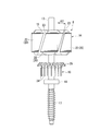
- FIG. 3 is a side view of the armature 8
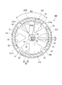
- FIG. 4 is a plan view of the armature core 14 seen from the axial direction.
- the armature 8 includes an armature core 14 fitted and fixed to the rotary shaft 13, a winding 15 wound around the armature core 14, and one end side of the rotary shaft 13 (FIG. 3). And a commutator 16 that is externally fitted and fixed to the lower end side.
- a worm shaft 17 constituting a worm speed reducer is integrally formed at one end of the rotating shaft 13.
- the worm shaft 17 is meshed with a worm wheel (not shown).
- the other end (upper end in FIG. 3) of the rotating shaft 13 is rotatably supported by a bearing (not shown) provided on the boss portion 9 of the yoke 7.
- a bearing 19 is provided at one end of the rotating shaft 13.
- the bearing 19 is attached to a brush holder (not shown) for supplying power to the winding 15.
- the brush holder is fixed to the casing 4. That is, one end of the rotating shaft 13 is rotatably supported by the casing 4 via the bearing 19 and the brush holder.
- the armature core 14 is formed by laminating a plate of magnetic material punched by pressing or the like in the axial direction (laminated core) or pressure-molding soft magnetic powder (a dust core). Thus, it has a substantially annular core body 18.
- the rotary shaft 13 is press-fitted and fixed at the center of the core body 18.
- the outer peripheral portion of the core body 18 is provided with six teeth 20 that are substantially T-shaped in a plan view in the axial direction, radially at equal intervals along the circumferential direction.
- Each tooth 20 extends in the radial direction so as to be symmetrical with respect to the winding drum portion 21 provided at the tip of the winding drum portion 21 and the winding drum portion 21 around which the winding 15 is wound.
- Part 22 That is, the flange portion 22 provided at the tip of the tooth 20 forms the outer peripheral surface of the armature core 14, and the flange portion 22 faces the permanent magnet 12.
- each dovetail-shaped slot 23 is formed between adjacent teeth 20.
- the slots 23 extend along the axial direction, and a plurality of slots 23 are formed at equal intervals along the circumferential direction.
- the enamel-wrapped winding 15 is inserted between the slots 23, and the winding 15 is wound on the winding body 21 of the teeth 20 via an insulator (not shown) as an insulating material.
- the teeth 20 and the slots 23 are formed with a skew angle ⁇ 2 so as to extend obliquely with respect to the axial direction of the rotating shaft 13.
- This skew angle ⁇ 2 is 0 ° ⁇ 2 ⁇ 20 ° (2) It is set to satisfy.
- the commutator 16 fitted and fixed to one end of the rotary shaft 13 is formed in a substantially cylindrical shape.
- a plurality of segments 24 made of a conductive material are attached to the outer peripheral surface of the commutator 16.
- the segments 24 are made of plate-like metal pieces that are long in the axial direction, and are fixed in parallel at equal intervals along the circumferential direction in a state of being insulated from each other.
- a riser 25 is integrally formed at the end portion of each segment 24 on the armature core 14 side so as to be folded back to the outer diameter side.
- a winding start end portion and a winding end end portion of the winding 15 are wound around the riser 25.
- the winding 15 is fixed to the riser 25 by fusing or the like. Thereby, the segment 24 and the coil
- the commutator 16 configured as described above is in a state of being exposed to the casing 4 when the electric motor 2 is attached to the speed reduction mechanism 3. Then, a brush (not shown) of a brush holder fixed to the casing 4 is brought into sliding contact with the segment 24 of the commutator 16. The brush is electrically connected to the connector 6 of the casing 4. As a result, power from the external power source is supplied to the winding 15 via the brush and the segment 24.
- FIG. 5 is a graph showing changes in torque ripple when the vertical axis is the torque ripple [mN ⁇ m] of the electric motor 2 and the horizontal axis is the skew angle ⁇ 2 [°] of the armature core 14.
- the vertical axis represents the cogging torque [mN ⁇ m] of the electric motor 2
- the horizontal axis represents the eccentric amount ⁇ [of the arc center P 1 of the inner surface arc portion 12 a and the arc center P 2 of the outer surface arc portion 12 b of the permanent magnet 12.
- mm] is a graph showing a change in cogging torque. 5 and 6, the polar arc angle ⁇ 11 of the permanent magnet 12 is assumed to satisfy the formula (1).
- the skew angle ⁇ 2 is 15 ° ⁇ ⁇ 2 ⁇ 20 ° In this range, it can be confirmed that the decrease gradient of the torque ripple becomes slightly gentle. For this reason, in the electric motor 2, the skew angle ⁇ 2 is set so as to satisfy the expression (2). In this case, as shown in FIG. 6, it can be confirmed that as the eccentricity ⁇ is increased, the cogging torque is hardly reduced, but the restraining torque is greatly reduced. For this reason, in the electric motor 2, the eccentricity ⁇ is set to 0 mm, that is, the thickness of the permanent magnet 12 is set to be substantially uniform.
- FIG. 7 is a cross-sectional view orthogonal to the axial direction of the electric motor 202 in the second embodiment, and corresponds to FIG. 2 described above.
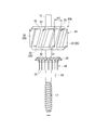
- FIG. 8 is a side view of the armature 208 and corresponds to FIG. 3 described above.
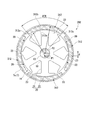
- FIG. 9 is a plan view of the armature core 14 viewed from the axial direction, and corresponds to FIG. 4 described above.
- the difference between the first embodiment and the second embodiment is that the shape of the permanent magnet 212 of the yoke 7 and the shape of the teeth 20 of the armature core 14 are different. is there.
- the four segment-type permanent magnets 212 provided on the inner peripheral surface of the cylindrical portion 7c of the yoke 7 are formed in a tile shape, and the inner surface arc portion 212a facing radially inward, It has an outer surface arcuate portion 212b that faces outward in the direction and corresponds to the shape of the inner peripheral surface of the cylindrical portion 7c of the yoke 7, and a pair of side surfaces 212c that form both ends in the circumferential direction.
- the arc center P1 of the inner surface arc portion 212a is eccentric with respect to the arc center P2 of the outer surface arc portion 212b.
- the eccentric direction is a direction away from the permanent magnet 212 along the thickness direction of the permanent magnet 212 from the arc center P2 of the outer arc portion 212b. That is, the arc center P2 of the outer surface arc portion 212b is located at the radial center of the yoke 7, while the arc center P1 of the inner surface arc portion 212a is shifted from the radial center of the yoke 7 downward in FIG. Exists.
- the amount of eccentricity ⁇ between the arc center P1 of the inner surface arc portion 212a and the arc center P2 of the outer surface arc portion 212b is: 0mm ⁇ ⁇ 3mm (3) It is set to satisfy.
- the polar arc angle ⁇ 21 of the permanent magnet 212 is 70 ° ⁇ ⁇ 21 ⁇ 80 ° (4) It is set to satisfy.
- each groove 31 and 32 is formed on the outer peripheral surface of the flange portion 22 over the entire axial direction.
- channel 31 and 32 is arrange
- Each groove 31 and 32 is formed with a skew angle ⁇ 2 along the extending direction of the teeth 20.
- the grooves 31 and 32 are formed so as to have different groove widths. That is, of the two grooves 31 and 32, the groove width of the first groove 31 is set to be narrower than the groove width of the second groove 32. Note that the skew angle ⁇ 2 of the teeth 20 and the slot 23 satisfies the above-described equation (2).
- the cogging torque gradually increases.
- the amount of eccentricity ⁇ is greater than 2.5 mm, the cogging torque increases. That is, the vertical axis is cogging torque [mN ⁇ m] of the electric motor 202, and the horizontal axis is the eccentric amount ⁇ [mm] between the arc center P1 of the inner surface arc portion 212a and the arc center P2 of the outer surface arc portion 212b of the permanent magnet 212.
- the amount of eccentricity ⁇ between the arc center P1 of the inner surface arc portion 212a and the arc center P2 of the outer surface arc portion 212b in the permanent magnet 212 satisfies the above equation (3).
- the polar arc angle ⁇ 21 of the permanent magnet 212 is set so as to satisfy the above formula (4), and the two grooves 31 and 32 are formed on the outer peripheral surface of the collar portion 22 of the tooth 20.
- FIG. 10 is a cross-sectional view orthogonal to the axial direction of the electric motor 302 in the third embodiment, and corresponds to FIG. 2 described above.
- the difference between the first embodiment and the third embodiment is that the shape of the permanent magnet 312 of the yoke 7 is different.
- the four segment-type permanent magnets 312 provided on the inner peripheral surface of the cylindrical portion 7c of the yoke 7 are formed in a tile shape, and the inner surface arc portion 312a facing radially inward, It has an outer surface arc portion 312b that faces outward in the direction and corresponds to the shape of the inner peripheral surface of the cylindrical portion 7c of the yoke 7, and a pair of side surfaces 312c that form both ends in the circumferential direction.
- the arc center P1 of the inner surface arc portion 312a is eccentric with respect to the arc center P2 of the outer surface arc portion 312b.
- the eccentric direction is a direction away from the permanent magnet 312 along the thickness direction of the permanent magnet 312 from the arc center P2 of the outer arc portion 312b. That is, the arc center P2 of the outer surface arc portion 312b is located at the radial center of the yoke 7, while the arc center P1 of the inner surface arc portion 312a is shifted from the radial center of the yoke 7 downward in FIG. Exists.
- the amount of eccentricity ⁇ between the arc center P1 of the inner surface arc portion 312a and the arc center P2 of the outer surface arc portion 312b is: 3 mm ⁇ ⁇ ⁇ 4 mm (5) It is set to satisfy.
- the polar arc angle ⁇ 31 of the permanent magnet 312 is 80 ° ⁇ ⁇ 31 ⁇ 90 ° (6) It is set to satisfy.
- the skew angle ⁇ 2 of the teeth 20 and the slots 23 satisfies the above-described equation (2).
- the vertical axis represents the cogging torque [mN ⁇ m] of the electric motor 302, and the horizontal axis represents the amount of eccentricity ⁇ [between the arc center P1 of the inner arc portion 312a and the arc center P2 of the outer arc portion 312b of the permanent magnet 312.
- mm is a graph showing a change in cogging torque.
- the polar arc angle ⁇ 31 of the permanent magnet 312 satisfies the formula (6). As shown in the figure, it can be confirmed that the cogging torque decreases as the amount of eccentricity ⁇ increases.
- the constraining torque does not substantially decrease until the eccentricity is close to 2.5 mm, but it can be confirmed that the decreasing gradient gradually increases when it exceeds 2.5 mm.
- the amount of eccentricity ⁇ is set so as to satisfy Expression (5).
- the eccentric amount ⁇ between the arc center P1 of the inner surface arc portion 312a and the arc center P2 of the outer surface arc portion 312b in the permanent magnet 312 satisfies the above-described equation (5).
- the polar arc angle ⁇ 31 of the permanent magnet 312 so as to satisfy the above-described formula (6), the same effects as those of the above-described first embodiment can be obtained.
- the present invention is not limited to the above-described embodiment, and includes various modifications made to the above-described embodiment without departing from the spirit of the present invention.
- the case where the electric motors 2, 202, 302 are connected to the speed reduction mechanism 3 to form the motor 1 with a speed reducer, and the motor 1 with the speed reducer is used as a wiper motor of an automobile has been described.
- the present invention is not limited to this, and the electric motors 2, 202, 302 can be used in various devices.
- the motor 1 with a reduction gear can also be used for various devices.
Landscapes
- Engineering & Computer Science (AREA)
- Power Engineering (AREA)
- Dc Machiner (AREA)
- Iron Core Of Rotating Electric Machines (AREA)
- Permanent Field Magnets Of Synchronous Machinery (AREA)
Abstract
永久磁石(12)を4つ備え、ティース(20)およびスロット(23)の数が6に設定された電動モータ(2)において、永久磁石(12)の極弧角をθ1とし、ティース(20)およびスロット(23)のスキュー角をθ2としたとき、極弧角θ1およびスキュー角θ2は、それぞれ50°≦θ1<70°,0°<θ2≦20°を満たすように設定されている。
Description
本発明は、電動モータに関するものである。
本願は、2015年4月28日に、日本に出願された特願2015-091834号に基づき優先権を主張し、その内容をここに援用する。
本願は、2015年4月28日に、日本に出願された特願2015-091834号に基づき優先権を主張し、その内容をここに援用する。
例えば、自動車用のワイパーモータとしては、ブラシ付きの電動モータを用いる場合が多い。この種の電動モータは、円筒状のヨークの内周面に複数の永久磁石を周方向に等間隔で配置し、これら永久磁石の内側にアーマチュアが回転自在に支持されている。永久磁石としては、略瓦状(略アーク状)に形成されたいわゆるセグメント型の永久磁石が用いられる。
アーマチュアは、複数のティースが放射状に形成されたアーマチュアコアを有している。各ティース間には、軸線方向に長いスロットが複数形成され、このスロットを介してティースに巻線が巻装されている。巻線は、アーマチュアコアと隣接するように回転軸に外嵌固定されたコンミテータに導通している。
アーマチュアは、複数のティースが放射状に形成されたアーマチュアコアを有している。各ティース間には、軸線方向に長いスロットが複数形成され、このスロットを介してティースに巻線が巻装されている。巻線は、アーマチュアコアと隣接するように回転軸に外嵌固定されたコンミテータに導通している。
コンミテータは、金属片である複数のセグメントが互いに絶縁された状態で周方向に配設されたものであって、これらセグメントにそれぞれ巻線の巻き始め端、および巻き終わり端が接続される。また、各セグメントはブラシに摺接可能に接続されており、このブラシを介してそれぞれの巻線に給電される。そして、給電された巻線によってティースに磁界が形成され、ヨークに設けられた永久磁石との間に生じる磁気的な吸引力や反発力によってアーマチュアが回転する。
ここで、コギングトルクやトルクリップルといったモータの作動音にかかる要因を低減するために、さまざまな技術が開示されている。
例えば、瓦状の永久磁石の外面の円弧中心の位置に対して内面の円弧中心の位置を偏心させ、ヨーク側の周方向における急激な磁束の変化を防止する技術が開示されている(例えば、特許文献1参照)。
例えば、瓦状の永久磁石の外面の円弧中心の位置に対して内面の円弧中心の位置を偏心させ、ヨーク側の周方向における急激な磁束の変化を防止する技術が開示されている(例えば、特許文献1参照)。
また、ティースの永久磁石の対向面に加工を施し、ティースに生じる磁束の粗密変化を低減する技術が開示されている(例えば、特許文献2参照)。
さらに、永久磁石の極弧角を限定することで、コギングトルクを低減する技術が開示されている(例えば、特許文献3参照)。
さらに、永久磁石の極弧角を限定することで、コギングトルクを低減する技術が開示されている(例えば、特許文献3参照)。
また、ティースやスロットを、軸方向に対して斜めに延在するようにスキュー角をつけて形成する技術が開示されている(例えば、特許文献4参照)。
このように構成することで、巻線による磁界とヨークに設けられた永久磁石との間に生じる磁気的な吸引力や反発力の発生タイミングを、軸方向でずらすことができる。
このように構成することで、巻線による磁界とヨークに設けられた永久磁石との間に生じる磁気的な吸引力や反発力の発生タイミングを、軸方向でずらすことができる。
ところで、ティースやスロットにスキュー角を持たせる場合、最適なスキュー角は、磁極数とスロット数との最小公倍数から導き出すことができる。すなわち、360°を磁極数とスロット数との最小公倍数で割った値が最適なスキュー角となる。例えば、磁極数が4極、スロット数が6の場合、最小公倍数は12であり、360°を12で割ると30°となる。したがって、磁極数が4極、スロット数が6の場合、最適なスキュー角は、30°となる。
しかしながら、上述の特許文献4のように、最適なスキュー角でティースやスロットを形成すると、角度が大きすぎてティースに巻線を巻装しにくくなってしまい、作業効率が悪化するという課題がある。
そこで、本発明は、作業効率を悪化させることなく、コギングトルクやトルクリップルを最小限に抑えることができる電動モータを提供する。
本発明の第1の態様によれば、電動モータは、筒部を有するヨークと、前記筒部の内周面に設けられ、4つのセグメント型の永久磁石と、前記ヨークの径方向内側に回転自在に支持されたアーマチュアと、を備え、前記永久磁石は、肉厚が均一となるように外面と内面とがそれぞれ円弧状に形成されており、前記アーマチュアは、回転軸と、該回転軸に固定されるアーマチュアコアと、前記回転軸に前記アーマチュアコアと隣接して設けられ複数のセグメントが周方向に配置されたコンミテータと、を備え、前記アーマチュアコアは、径方向に沿って放射状に延び、コイルを巻装するための6つのティースと、前記ティース間に形成され軸方向に沿って延びる6つのスロットと、を備え、前記ティースおよび前記スロットは、前記回転軸の軸方向に対して斜めに延在するようにスキュー角を有して形成されており、前記永久磁石の極弧角をθ1とし、前記スキュー角をθ2としたとき、極弧角θ1およびスキュー角θ2は、それぞれ
50°≦θ1<70°
0°<θ2≦20°
を満たすように設定されている。
50°≦θ1<70°
0°<θ2≦20°
を満たすように設定されている。
本発明の第2の態様によれば、電動モータは、筒部を有するヨークと、前記筒部の内周面に設けられ、4つのセグメント型の永久磁石と、前記ヨークの径方向内側に回転自在に支持されたアーマチュアと、を備え、前記永久磁石は、外面と内面とがそれぞれ円弧状に形成されており、前記内面の円弧中心が前記外面の円弧中心よりも前記永久磁石の周方向中央の厚さ方向に沿って前記永久磁石から離間する方向に向かって偏心し、前記アーマチュアは、回転軸と、該回転軸に固定されるアーマチュアコアと、前記回転軸に前記アーマチュアコアと隣接して設けられ複数のセグメントが周方向に配置されたコンミテータと、を備え、前記アーマチュアコアは、径方向に沿って放射状に延び、コイルを巻装するための6つのティースと、前記ティース間に形成され軸方向に沿って延びる6つのスロットと、を備え、前記ティースの前記永久磁石と対向する面には、溝幅の異なる2つの溝が前記回転軸の軸方向全体に渡って形成されており、前記ティースおよび前記スロットは、前記軸方向に対して斜めに延在するようにスキュー角を有して形成されており、前記永久磁石の前記内面の円弧中心の偏心量をδとし、前記永久磁石の極弧角をθ1とし、前記スキュー角をθ2としたとき、偏心量δ、極弧角θ1およびスキュー角θ2は、それぞれ
0mm<δ<3mm
70°≦θ1<80°
0°<θ2≦20°
を満たすように設定されている。
0mm<δ<3mm
70°≦θ1<80°
0°<θ2≦20°
を満たすように設定されている。
本発明の第3の態様によれば、電動モータは、筒部を有するヨークと、前記筒部の内周面に設けられ、4つのセグメント型の永久磁石と、前記ヨークの径方向内側に回転自在に支持されたアーマチュアと、を備え、前記永久磁石は、外面と内面とがそれぞれ円弧状に形成されており、前記内面の円弧中心が前記外面の円弧中心よりも前記永久磁石の周方向中央の厚さ方向に沿って前記永久磁石から離間する方向に向かって偏心し、前記アーマチュアは、回転軸と、該回転軸に固定されるアーマチュアコアと、前記回転軸に前記アーマチュアコアと隣接して設けられ複数のセグメントが周方向に配置されたコンミテータと、を備え、前記アーマチュアコアは、径方向に沿って放射状に延び、コイルを巻装するための6つのティースと、前記ティース間に形成され軸方向に沿って延びる6つのスロットと、を備え、前記ティースおよび前記スロットは、前記回転軸の軸方向に対して斜めに延在するようにスキュー角を有して形成されており、前記永久磁石の前記内面の円弧中心の偏心量をδとし、前記永久磁石の極弧角をθ1とし、前記スキュー角をθ2としたとき、偏心量δ、極弧角θ1およびスキュー角θ2は、それぞれ
3mm≦δ≦4mm
80°≦θ1<90°
0°<θ2≦20°
を満たすように設定されている。
3mm≦δ≦4mm
80°≦θ1<90°
0°<θ2≦20°
を満たすように設定されている。
上記の電動モータによれば、磁極数とスロット数から求められる最適なスキュー角に設定することなく、コギングトルクやトルクリップルを最小限に抑えることができる。このため、作業効率を悪化させることなく、モータ効率の優れた電動モータを提供できる。
次に、この発明の実施形態を図面に基づいて説明する。
(減速機付モータ)
図1は、本発明に係る電動モータ2が適用された減速機付モータ1の平面図である。
同図に示すように、減速機付モータ1は、例えば、自動車のワイパーモータとして用いられるものである。減速機付モータ1は、電動モータ2と、電動モータ2に連結された減速機構3と、を備えている。
図1は、本発明に係る電動モータ2が適用された減速機付モータ1の平面図である。
同図に示すように、減速機付モータ1は、例えば、自動車のワイパーモータとして用いられるものである。減速機付モータ1は、電動モータ2と、電動モータ2に連結された減速機構3と、を備えている。
減速機構3は、ケーシング4と、ケーシング4内に設けられたウォーム減速機と、ウォーム減速機を構成するウォームホイール(不図示)と一体化された出力軸5と、を備えている。そして、電動モータ2から出力された回転力は、ウォーム減速機を介して出力軸5から出力される。出力軸5は、不図示のワイパ機構に連結されており、減速機付モータ1が駆動することにより、ワイパ機構が駆動する。
また、ケーシング4には、コネクタ6が一体的に設けられている。このコネクタ6には、不図示の外部電源のコネクタが接続される。そして、コネクタ6を介して、電動モータ2に電力が供給される。
また、ケーシング4には、コネクタ6が一体的に設けられている。このコネクタ6には、不図示の外部電源のコネクタが接続される。そして、コネクタ6を介して、電動モータ2に電力が供給される。
(第1実施形態)
(電動モータ)
図2は、図1のA-A線に沿う断面図である。
図1、図2に示すように、電動モータ2は、いわゆるブラシ付きモータである。電動モータ2は、有底筒状のヨーク7と、ヨーク7の径方向内側に回転自在に配置されたアーマチュア8と、を備えている。
(電動モータ)
図2は、図1のA-A線に沿う断面図である。
図1、図2に示すように、電動モータ2は、いわゆるブラシ付きモータである。電動モータ2は、有底筒状のヨーク7と、ヨーク7の径方向内側に回転自在に配置されたアーマチュア8と、を備えている。
ヨーク7の底部7aには、径方向中央に軸線方向外側に向かって突出するボス部9が形成され、ここにアーマチュア8の回転軸13の一端を軸支するための軸受(不図示)が設けられている。
また、ヨーク7の開口部7bには、外フランジ部10が設けられている。外フランジ部10には、ボルト孔(不図示)が形成されている。このボルト孔にボルト11が挿通され、減速機構3のケーシング4に形成されたボルト孔(不図示)に螺入されることによって、ケーシング4にヨーク7が締結固定される。
また、ヨーク7の開口部7bには、外フランジ部10が設けられている。外フランジ部10には、ボルト孔(不図示)が形成されている。このボルト孔にボルト11が挿通され、減速機構3のケーシング4に形成されたボルト孔(不図示)に螺入されることによって、ケーシング4にヨーク7が締結固定される。
さらに、ヨーク7の筒部7cには、内周面に4つのセグメント型の永久磁石12が周方向に等間隔で、かつ磁極が順番となるように配設されている。すなわち、ヨーク7に設けられた永久磁石12は、磁極数が4極に設定されている。
セグメント型の永久磁石12は瓦状に形成されており、径方向内側に面する内面円弧部12aと、径方向外側に面し、ヨーク7の筒部7cの内周面形状に対応するように形成された外面円弧部12bと、周方向両端を形成する一対の側面12cと、を有している。
セグメント型の永久磁石12は瓦状に形成されており、径方向内側に面する内面円弧部12aと、径方向外側に面し、ヨーク7の筒部7cの内周面形状に対応するように形成された外面円弧部12bと、周方向両端を形成する一対の側面12cと、を有している。
また、永久磁石12は、肉厚がほぼ均一となるように形成されている。すなわち、内面円弧部12aの円弧中心P1と外面円弧部12bの円弧中心P2とが偏心しておらず、それぞれ同一位置、つまり、ヨーク7の径方向中心に位置している。
さらに、永久磁石12の極弧角θ11は、
50°≦θ11<70°・・・(1)
を満たすように設定されている。
さらに、永久磁石12の極弧角θ11は、
50°≦θ11<70°・・・(1)
を満たすように設定されている。
図3は、アーマチュア8の側面図、図4は、アーマチュアコア14を軸方向からみた平面図である。
図2~図4に示すように、アーマチュア8は、回転軸13に外嵌固定されたアーマチュアコア14と、アーマチュアコア14に巻装された巻線15と、回転軸13の一端側(図3における下端側)に外嵌固定されたコンミテータ16と、を備えている。
図2~図4に示すように、アーマチュア8は、回転軸13に外嵌固定されたアーマチュアコア14と、アーマチュアコア14に巻装された巻線15と、回転軸13の一端側(図3における下端側)に外嵌固定されたコンミテータ16と、を備えている。
回転軸13の一端には、ウォーム減速機を構成するウォーム軸17が一体成形されている。このウォーム軸17が、不図示のウォームホイールに噛合される。そして、回転軸13の他端(図3における上端)が、ヨーク7のボス部9に設けられた軸受(不図示)に回転自在に支持される。
一方、回転軸13の一端には、軸受19が設けられている。この軸受19は、巻線15に給電を行うためのブラシホルダ(不図示)に取り付けられている。ブラシホルダは、ケーシング4に固定されている。すなわち、回転軸13の一端は、軸受19およびブラシホルダを介してケーシング4に回転自在に支持されている。
一方、回転軸13の一端には、軸受19が設けられている。この軸受19は、巻線15に給電を行うためのブラシホルダ(不図示)に取り付けられている。ブラシホルダは、ケーシング4に固定されている。すなわち、回転軸13の一端は、軸受19およびブラシホルダを介してケーシング4に回転自在に支持されている。
アーマチュアコア14は、プレス加工等によって打ち抜かれた磁性材料の板材を軸方向に積層したり(積層コア)、軟磁性粉を加圧成形したり(圧粉コア)して形成されたものであって、略円環状のコア本体18を有している。このコア本体18の中心に回転軸13が圧入固定されている。
コア本体18の外周部には、軸方向平面視略T字型のティース20が6つ、周方向に沿って等間隔に、放射状に設けられている。各ティース20は、径方向に延出し巻線15が巻装される巻胴部21と、巻胴部21の先端に設けられ巻胴部21に対して左右対称となるように延在する鍔部22とにより構成されている。すなわち、ティース20の先端に設けられた鍔部22がアーマチュアコア14の外周面を構成しており、鍔部22が永久磁石12と対向した状態になる。
コア本体18の外周部に、ティース20を放射状に設けることによって、隣接するティース20間には、蟻溝状のスロット23が6つ形成されている。スロット23は軸線方向に沿って延びており、周方向に沿って等間隔に複数形成されている。
これらスロット23間にエナメル被覆の巻線15を挿通し、ティース20の巻胴部21に絶縁材であるインシュレータ(不図示)を介して巻線15が巻装される。
これらスロット23間にエナメル被覆の巻線15を挿通し、ティース20の巻胴部21に絶縁材であるインシュレータ(不図示)を介して巻線15が巻装される。
ここで、ティース20およびスロット23は、回転軸13の軸方向に対して斜めに延在するようにスキュー角θ2を有して形成されている。このスキュー角θ2は、
0°<θ2≦20°・・・(2)
を満たすように設定されている。
0°<θ2≦20°・・・(2)
を満たすように設定されている。
回転軸13の一端側に外嵌固定されたコンミテータ16は、略円柱状に形成されている。コンミテータ16の外周面には、導電材で形成されたセグメント24が複数枚取り付けられている。セグメント24は軸線方向に長い板状の金属片からなり、互いに絶縁された状態で周方向に沿って等間隔に並列に固定されている。
各セグメント24のアーマチュアコア14側の端部には、外径側に折り返す形で折り曲げられたライザ25が一体成形されている。ライザ25には、巻線15の巻き始め端部と巻き終わり端部とが掛け回わされる。そして、巻線15は、ヒュージングなどによりライザ25に固定される。これにより、セグメント24とこれに対応する巻線15とが導通される。
このように構成されたコンミテータ16は、減速機構3に電動モータ2を取り付けた状態では、ケーシング4に臨まされた状態になる。そして、コンミテータ16のセグメント24に、ケーシング4に固定されているブラシホルダのブラシ(何れも不図示)が摺接される。ブラシは、ケーシング4のコネクタ6に電気的に接続されている。これにより、外部電源の電力がブラシおよびセグメント24を介して巻線15に供給される。
巻線15に電力が供給されると、アーマチュアコア14に所定の磁界が発生する。そして、この磁界と、ヨーク7の永久磁石12との間に磁気的な吸引力や反発力が作用し、アーマチュア8が回転する。この回転によって、不図示のブラシが摺接するセグメント24が順次変更され、巻線15に流れる電流の向きが切替えられる、いわゆる整流が行われる。そして、アーマチュア8が継続的に回転する。
(モータ特性)
次に、図5、図6に基づいて、電動モータ2のモータ特性について説明する。
図5は、縦軸を電動モータ2のトルクリップル[mN・m]とし、横軸をアーマチュアコア14のスキュー角θ2[°]としたときのトルクリップルの変化を示すグラフである。
図6は、縦軸を電動モータ2のコギングトルク[mN・m]とし、横軸を永久磁石12における内面円弧部12aの円弧中心P1と外面円弧部12bの円弧中心P2との偏心量δ[mm]としたときのコギングトルクの変化を示すグラフである。
なお、図5、図6において、永久磁石12の極弧角θ11は、式(1)を満たすものとする。
次に、図5、図6に基づいて、電動モータ2のモータ特性について説明する。
図5は、縦軸を電動モータ2のトルクリップル[mN・m]とし、横軸をアーマチュアコア14のスキュー角θ2[°]としたときのトルクリップルの変化を示すグラフである。
図6は、縦軸を電動モータ2のコギングトルク[mN・m]とし、横軸を永久磁石12における内面円弧部12aの円弧中心P1と外面円弧部12bの円弧中心P2との偏心量δ[mm]としたときのコギングトルクの変化を示すグラフである。
なお、図5、図6において、永久磁石12の極弧角θ11は、式(1)を満たすものとする。
図5に示すように、電動モータ2のトルクリップルは、スキュー角θ2が大きくなるにしたがい、小さくなることが確認できる。なお、電動モータ2の磁極数は4極であり、スロット23の数は6であるので、最適なスキュー角θ2は、
360°/12=30°
となり、θ2=30°の場合に、トルクリップルがほぼ0[mN・m]になることが確認できる。
360°/12=30°
となり、θ2=30°の場合に、トルクリップルがほぼ0[mN・m]になることが確認できる。
ここで、図5に示すように、スキュー角θ2が、
15°≦θ2≦20°
の範囲であるとき、トルクリップルの減少勾配が僅かに緩やかになることが確認できる。このため、電動モータ2では、スキュー角θ2を、式(2)を満たすように設定する。
そして、この場合において、図6に示すように、偏心量δを大きくするにしたがって、コギングトルクの減少は殆ど確認できないものの、拘束トルクが大きく減少してしまうことが確認できる。このため、電動モータ2では、偏心量δを0mm、つまり、永久磁石12の肉厚をほぼ均一に設定した。
15°≦θ2≦20°
の範囲であるとき、トルクリップルの減少勾配が僅かに緩やかになることが確認できる。このため、電動モータ2では、スキュー角θ2を、式(2)を満たすように設定する。
そして、この場合において、図6に示すように、偏心量δを大きくするにしたがって、コギングトルクの減少は殆ど確認できないものの、拘束トルクが大きく減少してしまうことが確認できる。このため、電動モータ2では、偏心量δを0mm、つまり、永久磁石12の肉厚をほぼ均一に設定した。
したがって、上述の第1実施形態によれば、磁極数とスロット数から求められる最適なスキュー角に設定することなく、コギングトルクやトルクリップルを最小限に抑えることができる。このため、作業効率を悪化させることなく、モータ効率の優れた電動モータ2を提供できる。
(第2実施形態)
(電動モータ)
次に、この発明の第2実施形態を図7、図8に基づいて説明する。なお、第1実施形態と同一態様には、同一符号を付して説明する(以下の実施形態についても同様)。
図7は、第2実施形態における電動モータ202の軸方向に直交する断面図であって、前述の図2に対応している。図8は、アーマチュア208の側面図であって、前述の図3に対応している。図9は、アーマチュアコア14を軸方向からみた平面図であって、前述の図4に対応している。
図7~図9に示すように、前述の第1実施形態と第2実施形態との相違点は、ヨーク7の永久磁石212の形状と、アーマチュアコア14のティース20の形状とが異なる点にある。
(電動モータ)
次に、この発明の第2実施形態を図7、図8に基づいて説明する。なお、第1実施形態と同一態様には、同一符号を付して説明する(以下の実施形態についても同様)。
図7は、第2実施形態における電動モータ202の軸方向に直交する断面図であって、前述の図2に対応している。図8は、アーマチュア208の側面図であって、前述の図3に対応している。図9は、アーマチュアコア14を軸方向からみた平面図であって、前述の図4に対応している。
図7~図9に示すように、前述の第1実施形態と第2実施形態との相違点は、ヨーク7の永久磁石212の形状と、アーマチュアコア14のティース20の形状とが異なる点にある。
より具体的には、ヨーク7の筒部7cの内周面に設けられた4つのセグメント型の永久磁石212は瓦状に形成されており、径方向内側に面する内面円弧部212aと、径方向外側に面し、ヨーク7の筒部7cの内周面形状に対応するように形成された外面円弧部212bと、周方向両端を形成する一対の側面212cと、を有している。
ここで、永久磁石212は、内面円弧部212aの円弧中心P1が外面円弧部212bの円弧中心P2に対して偏芯している。偏芯方向は、外面円弧部212bの円弧中心P2から永久磁石212の肉厚方向に沿って、この永久磁石212から離間する方向である。つまり、外面円弧部212bの円弧中心P2は、ヨーク7の径方向中央に位置している一方、内面円弧部212aの円弧中心P1は、ヨーク7の径方向中央から図7における下方にずれた位置に存在している。
内面円弧部212aの円弧中心P1と外面円弧部212bの円弧中心P2との偏心量δは、
0mm<δ<3mm・・・(3)
を満たすように設定されている。
0mm<δ<3mm・・・(3)
を満たすように設定されている。
また、永久磁石212の極弧角θ21は、
70°≦θ21<80°・・・(4)
を満たすように設定されている。
70°≦θ21<80°・・・(4)
を満たすように設定されている。
一方、アーマチュアコア14のティース20には、鍔部22の外周面に、2つの溝31,32が軸方向全体に渡って形成されている。各溝31,32は、ティース20の巻胴部21の中心を挟んで周方向両側に並んで配置されている。また、各溝31,32は、ティース20の延在方向に沿うように、スキュー角θ2を有して形成されている。
さらに、各溝31,32は、それぞれ溝幅が異なるように形成されている。すなわち、2つの溝31,32のうち、第1溝31の溝幅は、第2溝32の溝幅よりも狭く設定されている。
なお、ティース20およびスロット23のスキュー角θ2は、前述の式(2)を満たしている。
さらに、各溝31,32は、それぞれ溝幅が異なるように形成されている。すなわち、2つの溝31,32のうち、第1溝31の溝幅は、第2溝32の溝幅よりも狭く設定されている。
なお、ティース20およびスロット23のスキュー角θ2は、前述の式(2)を満たしている。
このような構成のもと、仮に永久磁石212の内面円弧部12aの円弧中心P1と外面円弧部12bの円弧中心P2との偏心量δを、0mmから増大させていくと、コギングトルクは、徐々に減少していくが、偏心量δを2.5mmよりも大きくすると、逆にコギングトルクが増大していく。
つまり、縦軸を電動モータ202のコギングトルク[mN・m]とし、横軸を永久磁石212における内面円弧部212aの円弧中心P1と外面円弧部212bの円弧中心P2との偏心量δ[mm]としたときのコギングトルクの変化を示すグラフは、偏芯量δ=2.5mm付近を底として、V字状のグラフとなる。
つまり、縦軸を電動モータ202のコギングトルク[mN・m]とし、横軸を永久磁石212における内面円弧部212aの円弧中心P1と外面円弧部212bの円弧中心P2との偏心量δ[mm]としたときのコギングトルクの変化を示すグラフは、偏芯量δ=2.5mm付近を底として、V字状のグラフとなる。
したがって、上述の第2実施形態によれば、永久磁石212における内面円弧部212aの円弧中心P1と外面円弧部212bの円弧中心P2との偏心量δを、上述の式(3)を満たすように設定すると共に、永久磁石212の極弧角θ21を、上述の式(4)を満たすように設定し、かつ、ティース20の鍔部22の外周面に、2つの溝31,32を形成することにより、上述の第1実施形態と同様の効果を奏することができる。
(第3実施形態)
(電動モータ)
次に、この発明の第3実施形態を図10、図11に基づいて説明する。
図10は、第3実施形態における電動モータ302の軸方向に直交する断面図であって、前述の図2に対応している。
図10に示すように、前述の第1実施形態と第3実施形態との相違点は、ヨーク7の永久磁石312の形状が異なる点にある。
(電動モータ)
次に、この発明の第3実施形態を図10、図11に基づいて説明する。
図10は、第3実施形態における電動モータ302の軸方向に直交する断面図であって、前述の図2に対応している。
図10に示すように、前述の第1実施形態と第3実施形態との相違点は、ヨーク7の永久磁石312の形状が異なる点にある。
より具体的には、ヨーク7の筒部7cの内周面に設けられた4つのセグメント型の永久磁石312は瓦状に形成されており、径方向内側に面する内面円弧部312aと、径方向外側に面し、ヨーク7の筒部7cの内周面形状に対応するように形成された外面円弧部312bと、周方向両端を形成する一対の側面312cと、を有している。
ここで、永久磁石312は、内面円弧部312aの円弧中心P1が外面円弧部312bの円弧中心P2に対して偏芯している。偏芯方向は、外面円弧部312bの円弧中心P2から永久磁石312の肉厚方向に沿って、この永久磁石312から離間する方向である。つまり、外面円弧部312bの円弧中心P2は、ヨーク7の径方向中央に位置している一方、内面円弧部312aの円弧中心P1は、ヨーク7の径方向中央から図10における下方にずれた位置に存在している。
内面円弧部312aの円弧中心P1と外面円弧部312bの円弧中心P2との偏心量δは、
3mm≦δ≦4mm・・・(5)
を満たすように設定されている。
3mm≦δ≦4mm・・・(5)
を満たすように設定されている。
また、永久磁石312の極弧角θ31は、
80°≦θ31<90°・・・(6)
を満たすように設定されている。
なお、第3実施形態では特に図示しないが、ティース20およびスロット23のスキュー角θ2は、前述の式(2)を満たしている。
80°≦θ31<90°・・・(6)
を満たすように設定されている。
なお、第3実施形態では特に図示しないが、ティース20およびスロット23のスキュー角θ2は、前述の式(2)を満たしている。
図11は、縦軸を電動モータ302のコギングトルク[mN・m]とし、横軸を永久磁石312における内面円弧部312aの円弧中心P1と外面円弧部312bの円弧中心P2との偏心量δ[mm]としたときのコギングトルクの変化を示すグラフである。
なお、図11において、永久磁石312の極弧角θ31は、式(6)を満たすものとする。
同図に示すように、偏心量δを大きくするにしたがって、コギングトルクが減少していくのが確認できる。一方、拘束トルクは、偏心量が2.5mm付近まではほぼ減少が見られないが、2.5mmを超えると、減少勾配が徐々に大きくなっていくことが確認できる。このため、電動モータ302では、偏心量δを、式(5)を満たすように設定した。
なお、図11において、永久磁石312の極弧角θ31は、式(6)を満たすものとする。
同図に示すように、偏心量δを大きくするにしたがって、コギングトルクが減少していくのが確認できる。一方、拘束トルクは、偏心量が2.5mm付近まではほぼ減少が見られないが、2.5mmを超えると、減少勾配が徐々に大きくなっていくことが確認できる。このため、電動モータ302では、偏心量δを、式(5)を満たすように設定した。
したがって、上述の第3実施形態によれば、永久磁石312における内面円弧部312aの円弧中心P1と外面円弧部312bの円弧中心P2との偏心量δを、上述の式(5)を満たすように設定すると共に、永久磁石312の極弧角θ31を、上述の式(6)を満たすように設定することにより、上述の第1実施形態と同様の効果を奏することができる。
なお、本発明は上述の実施形態に限られるものではなく、本発明の趣旨を逸脱しない範囲において、上述の実施形態に種々の変更を加えたものを含む。
例えば、上述の実施形態では、電動モータ2,202,302を減速機構3と連結して減速機付モータ1とし、この減速機付モータ1を自動車のワイパーモータとして用いる場合について説明した。しかしながら、これに限られるものではなく、電動モータ2,202,302単独で、さまざまな装置に用いることができる。また、減速機付モータ1も、さまざまな装置に用いることが可能である。
例えば、上述の実施形態では、電動モータ2,202,302を減速機構3と連結して減速機付モータ1とし、この減速機付モータ1を自動車のワイパーモータとして用いる場合について説明した。しかしながら、これに限られるものではなく、電動モータ2,202,302単独で、さまざまな装置に用いることができる。また、減速機付モータ1も、さまざまな装置に用いることが可能である。
上記の電動モータによれば、磁極数とスロット数から求められる最適なスキュー角に設定することなく、コギングトルクやトルクリップルを最小限に抑えることができる。このため、作業効率を悪化させることなく、モータ効率の優れた電動モータを提供できる。
1…減速機付モータ
2,202,302…電動モータ
7…ヨーク
7c…筒部
8…アーマチュア
12,212,312…永久磁石
12a,212a,312a…内面円弧部(内面)
12b,212b,312b…外面円弧部(外面)
13…回転軸
14…アーマチュアコア
16…コンミテータ
20…ティース
23…スロット
24…セグメント
31…第1溝(溝)
32…第2溝(溝)
θ11、θ21,θ31…極弧角
θ2…スキュー角
δ…偏心量
2,202,302…電動モータ
7…ヨーク
7c…筒部
8…アーマチュア
12,212,312…永久磁石
12a,212a,312a…内面円弧部(内面)
12b,212b,312b…外面円弧部(外面)
13…回転軸
14…アーマチュアコア
16…コンミテータ
20…ティース
23…スロット
24…セグメント
31…第1溝(溝)
32…第2溝(溝)
θ11、θ21,θ31…極弧角
θ2…スキュー角
δ…偏心量
Claims (3)
- 筒部を有するヨークと、
前記筒部の内周面に設けられ、4つのセグメント型の永久磁石と、
前記ヨークの径方向内側に回転自在に支持されたアーマチュアと、
を備え、
前記永久磁石は、肉厚が均一となるように外面と内面とがそれぞれ円弧状に形成されており、
前記アーマチュアは、
回転軸と、
該回転軸に固定されるアーマチュアコアと、
前記回転軸に前記アーマチュアコアと隣接して設けられ複数のセグメントが周方向に配置されたコンミテータと、
を備え、
前記アーマチュアコアは、
径方向に沿って放射状に延び、コイルを巻装するための6つのティースと、
前記ティース間に形成され軸方向に沿って延びる6つのスロットと、
を備え、
前記ティースおよび前記スロットは、前記回転軸の軸方向に対して斜めに延在するようにスキュー角を有して形成されており、
前記永久磁石の極弧角をθ1とし、前記スキュー角をθ2としたとき、極弧角θ1およびスキュー角θ2は、それぞれ
50°≦θ1<70°
0°<θ2≦20°
を満たすように設定されている電動モータ。 - 筒部を有するヨークと、
前記筒部の内周面に設けられ、4つのセグメント型の永久磁石と、
前記ヨークの径方向内側に回転自在に支持されたアーマチュアと、
を備え、
前記永久磁石は、
外面と内面とがそれぞれ円弧状に形成されており、
前記内面の円弧中心が前記外面の円弧中心よりも前記永久磁石の周方向中央の厚さ方向に沿って前記永久磁石から離間する方向に向かって偏心し、
前記アーマチュアは、
回転軸と、
該回転軸に固定されるアーマチュアコアと、
前記回転軸に前記アーマチュアコアと隣接して設けられ複数のセグメントが周方向に配置されたコンミテータと、
を備え、
前記アーマチュアコアは、
径方向に沿って放射状に延び、コイルを巻装するための6つのティースと、
前記ティース間に形成され軸方向に沿って延びる6つのスロットと、
を備え、
前記ティースの前記永久磁石と対向する面には、溝幅の異なる2つの溝が前記回転軸の軸方向全体に渡って形成されており、
前記ティースおよび前記スロットは、前記軸方向に対して斜めに延在するようにスキュー角を有して形成されており、
前記永久磁石の前記内面の円弧中心の偏心量をδとし、前記永久磁石の極弧角をθ1とし、前記スキュー角をθ2としたとき、偏心量δ、極弧角θ1およびスキュー角θ2は、それぞれ
0mm<δ<3mm
70°≦θ1<80°
0°<θ2≦20°
を満たすように設定されている電動モータ。 - 筒部を有するヨークと、
前記筒部の内周面に設けられ、4つのセグメント型の永久磁石と、
前記ヨークの径方向内側に回転自在に支持されたアーマチュアと、
を備え、
前記永久磁石は、
外面と内面とがそれぞれ円弧状に形成されており、
前記内面の円弧中心が前記外面の円弧中心よりも前記永久磁石の周方向中央の厚さ方向に沿って前記永久磁石から離間する方向に向かって偏心し、
前記アーマチュアは、
回転軸と、
該回転軸に固定されるアーマチュアコアと、
前記回転軸に前記アーマチュアコアと隣接して設けられ複数のセグメントが周方向に配置されたコンミテータと、
を備え、
前記アーマチュアコアは、
径方向に沿って放射状に延び、コイルを巻装するための6つのティースと、
前記ティース間に形成され軸方向に沿って延びる6つのスロットと、
を備え、
前記ティースおよび前記スロットは、前記回転軸の軸方向に対して斜めに延在するようにスキュー角を有して形成されており、
前記永久磁石の前記内面の円弧中心の偏心量をδとし、前記永久磁石の極弧角をθ1とし、前記スキュー角をθ2としたとき、偏心量δ、極弧角θ1およびスキュー角θ2は、それぞれ
3mm≦δ≦4mm
80°≦θ1<90°
0°<θ2≦20°
を満たすように設定されている電動モータ。
Priority Applications (3)
| Application Number | Priority Date | Filing Date | Title |
|---|---|---|---|
| CN201680019031.9A CN107431424A (zh) | 2015-04-28 | 2016-04-25 | 电动机 |
| US15/560,187 US10756584B2 (en) | 2015-04-28 | 2016-04-25 | Electric motor |
| EP16786458.6A EP3291426B1 (en) | 2015-04-28 | 2016-04-25 | Electric motor |
Applications Claiming Priority (2)
| Application Number | Priority Date | Filing Date | Title |
|---|---|---|---|
| JP2015091834A JP6530956B2 (ja) | 2015-04-28 | 2015-04-28 | 電動モータ |
| JP2015-091834 | 2015-04-28 |
Publications (1)
| Publication Number | Publication Date |
|---|---|
| WO2016175181A1 true WO2016175181A1 (ja) | 2016-11-03 |
Family
ID=57198579
Family Applications (1)
| Application Number | Title | Priority Date | Filing Date |
|---|---|---|---|
| PCT/JP2016/062937 Ceased WO2016175181A1 (ja) | 2015-04-28 | 2016-04-25 | 電動モータ |
Country Status (5)
| Country | Link |
|---|---|
| US (1) | US10756584B2 (ja) |
| EP (1) | EP3291426B1 (ja) |
| JP (1) | JP6530956B2 (ja) |
| CN (1) | CN107431424A (ja) |
| WO (1) | WO2016175181A1 (ja) |
Cited By (1)
| Publication number | Priority date | Publication date | Assignee | Title |
|---|---|---|---|---|
| WO2020063536A1 (zh) * | 2018-09-30 | 2020-04-02 | 广东肇庆爱龙威机电有限公司 | 车辆座椅及其永磁直流电机 |
Families Citing this family (4)
| Publication number | Priority date | Publication date | Assignee | Title |
|---|---|---|---|---|
| JP2020022224A (ja) * | 2018-07-30 | 2020-02-06 | 株式会社ミツバ | 電動モータ |
| JP2020022225A (ja) * | 2018-07-30 | 2020-02-06 | 株式会社ミツバ | 電動モータ |
| KR20200086087A (ko) * | 2019-01-08 | 2020-07-16 | 엘지이노텍 주식회사 | 모터 |
| CN114172336A (zh) * | 2021-11-29 | 2022-03-11 | 深圳市精锐电机有限公司 | 一种永磁式旋转外转子电机 |
Citations (4)
| Publication number | Priority date | Publication date | Assignee | Title |
|---|---|---|---|---|
| JPS60261344A (ja) * | 1984-06-06 | 1985-12-24 | Mitsubishi Chem Ind Ltd | モ−タ− |
| JPH11178301A (ja) * | 1997-12-15 | 1999-07-02 | Matsushita Electric Works Ltd | モータ |
| JP2000253604A (ja) * | 1999-03-03 | 2000-09-14 | Mitsubishi Electric Corp | 直流電動機 |
| JP2004270563A (ja) * | 2003-03-10 | 2004-09-30 | Aisan Ind Co Ltd | 電子スロットル装置 |
Family Cites Families (15)
| Publication number | Priority date | Publication date | Assignee | Title |
|---|---|---|---|---|
| JPS62193539A (ja) * | 1986-02-17 | 1987-08-25 | Sankyo Seiki Mfg Co Ltd | 直流モ−タ |
| JPS63181633A (ja) * | 1987-01-21 | 1988-07-26 | Tamagawa Seiki Co Ltd | 電動機 |
| US5773908A (en) | 1993-02-22 | 1998-06-30 | General Electric Company | Single phase motor with positive torque parking positions |
| JP3469164B2 (ja) * | 2000-05-02 | 2003-11-25 | 三菱電機株式会社 | 回転電機 |
| JP2002315237A (ja) | 2001-04-16 | 2002-10-25 | Mitsubishi Electric Corp | 回転電機の積層鉄心 |
| JP2008160908A (ja) * | 2006-12-21 | 2008-07-10 | Mabuchi Motor Co Ltd | 小型モータ |
| CN101222153B (zh) | 2007-01-12 | 2012-03-14 | 台达电子工业股份有限公司 | 永磁电机的转动结构及决定其转动结构的方法 |
| CN102171912B (zh) * | 2008-10-07 | 2013-09-04 | 株式会社美姿把 | 电动机及带减速器电机 |
| JP2010093939A (ja) * | 2008-10-07 | 2010-04-22 | Mitsuba Corp | 電動モータ |
| CN102059954B (zh) * | 2009-11-17 | 2015-04-29 | 德昌电机(深圳)有限公司 | 电动驻车制动系统及其永磁直流电机 |
| JP5111535B2 (ja) | 2010-02-05 | 2013-01-09 | 三菱電機株式会社 | 永久磁石型回転電機 |
| CN102035332B (zh) * | 2010-12-27 | 2012-07-04 | 重庆青山工业有限责任公司 | 一种用于电控机械式自动变速器的电机 |
| CN102255437B (zh) * | 2011-07-07 | 2013-08-07 | 常州市昊升电机有限公司 | 一种高性能的稀土永磁直流电动机 |
| JP2013031284A (ja) | 2011-07-28 | 2013-02-07 | Mitsuba Corp | アーマチュアコアおよびインナロータ型電動モータ |
| CN202260673U (zh) * | 2011-08-25 | 2012-05-30 | 江苏上骐集团有限公司 | 一种用于交流永磁伺服电动机的定子冲片 |
-
2015
- 2015-04-28 JP JP2015091834A patent/JP6530956B2/ja not_active Expired - Fee Related
-
2016
- 2016-04-25 CN CN201680019031.9A patent/CN107431424A/zh active Pending
- 2016-04-25 WO PCT/JP2016/062937 patent/WO2016175181A1/ja not_active Ceased
- 2016-04-25 US US15/560,187 patent/US10756584B2/en not_active Expired - Fee Related
- 2016-04-25 EP EP16786458.6A patent/EP3291426B1/en active Active
Patent Citations (4)
| Publication number | Priority date | Publication date | Assignee | Title |
|---|---|---|---|---|
| JPS60261344A (ja) * | 1984-06-06 | 1985-12-24 | Mitsubishi Chem Ind Ltd | モ−タ− |
| JPH11178301A (ja) * | 1997-12-15 | 1999-07-02 | Matsushita Electric Works Ltd | モータ |
| JP2000253604A (ja) * | 1999-03-03 | 2000-09-14 | Mitsubishi Electric Corp | 直流電動機 |
| JP2004270563A (ja) * | 2003-03-10 | 2004-09-30 | Aisan Ind Co Ltd | 電子スロットル装置 |
Cited By (1)
| Publication number | Priority date | Publication date | Assignee | Title |
|---|---|---|---|---|
| WO2020063536A1 (zh) * | 2018-09-30 | 2020-04-02 | 广东肇庆爱龙威机电有限公司 | 车辆座椅及其永磁直流电机 |
Also Published As
| Publication number | Publication date |
|---|---|
| EP3291426A4 (en) | 2018-11-21 |
| CN107431424A (zh) | 2017-12-01 |
| US10756584B2 (en) | 2020-08-25 |
| US20180083501A1 (en) | 2018-03-22 |
| JP6530956B2 (ja) | 2019-06-12 |
| EP3291426B1 (en) | 2020-03-25 |
| JP2016208800A (ja) | 2016-12-08 |
| EP3291426A1 (en) | 2018-03-07 |
Similar Documents
| Publication | Publication Date | Title |
|---|---|---|
| US9071118B2 (en) | Axial motor | |
| JP4440275B2 (ja) | 三相回転電機 | |
| JP2021531723A (ja) | 非対称な極を有する、電気機械のための回転子 | |
| JP2009273304A (ja) | 回転電機のロータ及び回転電機 | |
| WO2016175181A1 (ja) | 電動モータ | |
| JP2017063599A (ja) | 単相ブラシレスモータ及びこれを利用する動力工具 | |
| JP2014533086A (ja) | 厚さが異なる永久磁石を有する回転子及びそれを含むモータ | |
| JP4735210B2 (ja) | モータ | |
| JP2006060952A (ja) | 永久磁石埋込み型電動機 | |
| KR100677280B1 (ko) | 부등슬롯형 스테이터 및 이를 구비한 하이브리드 인덕션모터 | |
| WO2016060232A1 (ja) | ダブルステータ型回転機 | |
| JP2012124984A (ja) | 回転電機 | |
| JP2013118788A (ja) | ブラシレスモータ | |
| US20090200876A1 (en) | Synchronous reluctance motor | |
| JP6052961B2 (ja) | ステータ及びこれを備えた回転電機 | |
| JP5668181B1 (ja) | 磁石式発電機 | |
| JP6399071B2 (ja) | 回転電機 | |
| JP5491344B2 (ja) | モータ | |
| JP2009124892A (ja) | 電動モータ | |
| JP4770434B2 (ja) | モータ | |
| JP6294426B2 (ja) | モータ | |
| JP6451886B2 (ja) | モータ | |
| JP6298133B2 (ja) | モータ | |
| JP2020022224A (ja) | 電動モータ | |
| JP2012016127A (ja) | モータ |
Legal Events
| Date | Code | Title | Description |
|---|---|---|---|
| 121 | Ep: the epo has been informed by wipo that ep was designated in this application |
Ref document number: 16786458 Country of ref document: EP Kind code of ref document: A1 |
|
| REEP | Request for entry into the european phase |
Ref document number: 2016786458 Country of ref document: EP |
|
| WWE | Wipo information: entry into national phase |
Ref document number: 15560187 Country of ref document: US |
|
| NENP | Non-entry into the national phase |
Ref country code: DE |