WO2016175231A1 - 燃料電池スタック - Google Patents
燃料電池スタック Download PDFInfo
- Publication number
- WO2016175231A1 WO2016175231A1 PCT/JP2016/063156 JP2016063156W WO2016175231A1 WO 2016175231 A1 WO2016175231 A1 WO 2016175231A1 JP 2016063156 W JP2016063156 W JP 2016063156W WO 2016175231 A1 WO2016175231 A1 WO 2016175231A1
- Authority
- WO
- WIPO (PCT)
- Prior art keywords
- fuel
- cell stack
- fuel cell
- power generation
- interconnector
- Prior art date
- Legal status (The legal status is an assumption and is not a legal conclusion. Google has not performed a legal analysis and makes no representation as to the accuracy of the status listed.)
- Ceased
Links
Images






Classifications
-
- H—ELECTRICITY
- H01—ELECTRIC ELEMENTS
- H01M—PROCESSES OR MEANS, e.g. BATTERIES, FOR THE DIRECT CONVERSION OF CHEMICAL ENERGY INTO ELECTRICAL ENERGY
- H01M8/00—Fuel cells; Manufacture thereof
- H01M8/02—Details
-
- H—ELECTRICITY
- H01—ELECTRIC ELEMENTS
- H01M—PROCESSES OR MEANS, e.g. BATTERIES, FOR THE DIRECT CONVERSION OF CHEMICAL ENERGY INTO ELECTRICAL ENERGY
- H01M8/00—Fuel cells; Manufacture thereof
- H01M8/02—Details
- H01M8/0202—Collectors; Separators, e.g. bipolar separators; Interconnectors
-
- H—ELECTRICITY
- H01—ELECTRIC ELEMENTS
- H01M—PROCESSES OR MEANS, e.g. BATTERIES, FOR THE DIRECT CONVERSION OF CHEMICAL ENERGY INTO ELECTRICAL ENERGY
- H01M8/00—Fuel cells; Manufacture thereof
- H01M8/02—Details
- H01M8/0271—Sealing or supporting means around electrodes, matrices or membranes
-
- H—ELECTRICITY
- H01—ELECTRIC ELEMENTS
- H01M—PROCESSES OR MEANS, e.g. BATTERIES, FOR THE DIRECT CONVERSION OF CHEMICAL ENERGY INTO ELECTRICAL ENERGY
- H01M8/00—Fuel cells; Manufacture thereof
- H01M8/24—Grouping of fuel cells, e.g. stacking of fuel cells
- H01M8/2465—Details of groupings of fuel cells
- H01M8/2484—Details of groupings of fuel cells characterised by external manifolds
- H01M8/2485—Arrangements for sealing external manifolds; Arrangements for mounting external manifolds around a stack
-
- H—ELECTRICITY
- H01—ELECTRIC ELEMENTS
- H01M—PROCESSES OR MEANS, e.g. BATTERIES, FOR THE DIRECT CONVERSION OF CHEMICAL ENERGY INTO ELECTRICAL ENERGY
- H01M8/00—Fuel cells; Manufacture thereof
- H01M8/10—Fuel cells with solid electrolytes
- H01M8/12—Fuel cells with solid electrolytes operating at high temperature, e.g. with stabilised ZrO2 electrolyte
-
- Y—GENERAL TAGGING OF NEW TECHNOLOGICAL DEVELOPMENTS; GENERAL TAGGING OF CROSS-SECTIONAL TECHNOLOGIES SPANNING OVER SEVERAL SECTIONS OF THE IPC; TECHNICAL SUBJECTS COVERED BY FORMER USPC CROSS-REFERENCE ART COLLECTIONS [XRACs] AND DIGESTS
- Y02—TECHNOLOGIES OR APPLICATIONS FOR MITIGATION OR ADAPTATION AGAINST CLIMATE CHANGE
- Y02E—REDUCTION OF GREENHOUSE GAS [GHG] EMISSIONS, RELATED TO ENERGY GENERATION, TRANSMISSION OR DISTRIBUTION
- Y02E60/00—Enabling technologies; Technologies with a potential or indirect contribution to GHG emissions mitigation
- Y02E60/30—Hydrogen technology
- Y02E60/50—Fuel cells
Definitions
- the technology disclosed in this specification relates to a fuel cell stack.
- a solid oxide fuel cell (hereinafter also referred to as “SOFC”) is generally used in the form of a fuel cell stack including a plurality of power generation units arranged in a predetermined direction (hereinafter also referred to as “array direction”). Is done.
- the power generation unit is the minimum unit of power generation, and includes an electrolyte layer and an air electrode and a fuel electrode facing each other in the arrangement direction with the electrolyte layer interposed therebetween.
- the fuel cell stack has a plurality of bolt holes extending in the arrangement direction over a plurality of power generation units, and is fastened by bolts inserted into the plurality of bolt holes, respectively.
- a plurality of gas flow paths (also called “manifolds”) extending over a plurality of power generation units are formed.
- Fuel gas and oxidant gas are supplied to the fuel chamber facing the fuel electrode and the air chamber facing the air electrode of each power generation unit through each gas flow path, respectively.
- Fuel off-gas and oxidant off-gas are discharged from the chamber, respectively.
- a form of a fuel cell stack that uses the above-described plurality of bolt holes also as the above-described plurality of gas flow paths is known.
- the space formed between the inner peripheral surface of the bolt hole and the outer peripheral surface of the shaft portion of the bolt inserted into the bolt hole, or the space formed inside the shaft portion of the bolt is a gas flow path.
- the contaminant contained in the bolt is carried to the fuel chamber or the air chamber by the gas flow in the gas flow path, and may adhere to the fuel electrode or the air electrode, causing a contamination phenomenon that decreases the reaction rate of the electrode. is there.
- each bolt when the temperature of the gas flowing through each gas flow path is different from each other, each bolt is exposed to a gas having a different temperature, so that a difference occurs in the deformation amount due to thermal expansion of each bolt, and the fuel cell stack
- the pressure hereinafter also referred to as “contact pressure”
- contact pressure for holding the fuel cell stack in the arrangement direction varies in the surface direction (direction perpendicular to the arrangement direction), and gas may leak from the inside of the fuel cell stack to the outside.
- each power generation unit is disposed between the metal interconnector, the metal separator that partitions the fuel chamber and the air chamber, and the through hole that constitutes the fuel chamber between the separator and the interconnector.
- the fuel gas may leak to the bolt hole through the separator and the frame member or between the frame member and the interconnector. If the fuel gas leaks into the bolt hole, the efficiency of the fuel cell stack decreases, which is not preferable.
- the packing formed of the metal foil is disposed between the frame member and the interconnector. However, in this configuration, the leakage of the fuel gas to the bolt hole cannot be sufficiently suppressed.
- each power generation unit includes a metal interconnector, a metal separator, and a metal frame member that is disposed between the separator and the interconnector and has a through hole that forms an air chamber.
- the oxidant gas may leak to the bolt hole through between the separator and the frame member or between the frame member and the interconnector.
- SOFC sulfur-oxide-semiconductor
- a fuel cell stack disclosed in the present specification includes a plurality of power generation units arranged side by side in a first direction and a plurality of bolt holes extending in the first direction across the plurality of power generation units.
- Each of the power generating units includes an electrolyte layer and an air electrode and a fuel electrode facing each other in the first direction with the electrolyte layer interposed therebetween.
- a single cell including the single cell, a metal interconnector facing the single cell in the first direction, a through hole is formed, and a portion surrounding the through hole is joined to a peripheral portion of the single cell, and the air
- a metal separator that divides an air chamber facing the electrode and a fuel chamber facing the fuel electrode, and is disposed between the separator and the interconnector to constitute the fuel chamber or the air chamber
- a plurality of gas flow paths extending over the plurality of power generation units are formed in the fuel cell stack.
- a first seal portion for joining and sealing at least one of between the separator and the frame member and between the frame member and the interconnector. It is formed so as to surround the bolt hole.
- the first seal portion is formed so as to surround each bolt hole, gas leakage from the gas flow path, the fuel chamber, or the air chamber to the bolt hole is suppressed. And a reduction in the power generation efficiency of the fuel cell stack can be suppressed.
- the first seal portion seals both between the separator and the frame member and between the frame member and the interconnector. It is good also as a structure. According to this fuel cell stack, the first seal portion is formed so as to seal both between the separator and the frame member and between the frame member and the interconnector. Leakage of gas from the chamber or the air chamber to the bolt hole can be suppressed, and a reduction in power generation efficiency of the fuel cell stack can be effectively suppressed.
- the other interconnect which is the interconnector included in the separator included in one power generation unit and the other power generation unit located next to the one power generation unit in the first direction.
- a second seal portion that is joined and sealed so as to surround at least one of the gas flow paths may be formed between the connector and the connector.
- the fuel cell stack may further include a third seal portion that joins and seals at least one of the separator and the frame member, and the frame member and the interconnector,
- the third seal portion is continuous so as to pass between each of the plurality of gas flow paths and the outer peripheral edge of each power generation unit and to surround the plurality of gas flow paths in the first direction view. It is good also as a structure characterized by being formed. According to the fuel cell stack, since the third seal portion is continuously formed so as to surround the plurality of gas flow paths, the gas flows from the plurality of gas flow paths to which the gas should originally flow to the outside of the fuel cell stack. Can be suppressed, and a decrease in power generation efficiency of the fuel cell stack can be further effectively suppressed.
- the third seal portion may be formed along an outer peripheral shape of each power generation unit. According to the fuel cell stack, since the third seal portion is formed along the outer peripheral shape of each power generation unit, the gas flow path, the fuel chamber or the air chamber where the gas should originally flow from the fuel cell stack to the outside. Gas leakage can be suppressed, and a reduction in power generation efficiency of the fuel cell stack can be further effectively suppressed.
- the first seal portion may be a welded portion. According to this fuel cell stack, since the first seal part is formed by a welded part that can be expected to have high sealing performance, it is more reliable that gas leaks from the gas flow path, the fuel chamber, or the air chamber to the bolt hole. It is possible to suppress the decrease in power generation efficiency of the fuel cell stack more effectively.
- the technology disclosed in this specification can be realized in various forms, for example, in the form of a fuel cell stack, a power generation module including the fuel cell stack, a fuel cell system including the power generation module, and the like. Is possible.
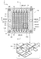
- FIG. 1 is a perspective view showing an external configuration of a fuel cell stack 100.
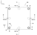
- FIG. 2 is an explanatory diagram showing an XY plane configuration on the upper side of the fuel cell stack 100.
- FIG. 2 is an explanatory view showing an XY plane configuration on the lower side of the fuel cell stack 100.
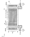
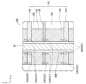
- FIG. 4 is an explanatory diagram showing an XZ cross-sectional configuration of a fuel cell stack 100 at a position IV-IV in FIGS. 1 to 3.
- FIG. 4 is an explanatory diagram showing a YZ cross-sectional configuration of the fuel cell stack 100 at the position VV in FIGS. 1 to 3. It is explanatory drawing which shows XZ cross-section structure of the two electric power generation units 102 adjacent to each other in the same position as the cross section shown in FIG.
- FIG. 7 is an explanatory diagram showing an XY cross-sectional configuration of a power generation unit at a position of VIII-VIII in FIG. 6.
- FIG. 7 is an explanatory diagram showing an XY cross-sectional configuration of a power generation unit at a position IX-IX in FIG. 6.
- FIG. 7 is an explanatory diagram showing an XY cross-sectional configuration of a power generation unit at a position XX in FIG.
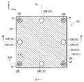
- FIG. 7 is an explanatory diagram showing an XY cross-sectional configuration of a power generation unit 102 at a position XI-XI in FIG. 6.
- FIG. 5 is an explanatory diagram showing a configuration of a gas seal at a position of a fuel electrode side frame 140.
- FIGS. 1 to 5 are explanatory views schematically showing the configuration of the fuel cell stack 100 in the present embodiment.
- FIG. 1 shows an external configuration of the fuel cell stack 100
- FIG. 2 shows a planar configuration of the upper side of the fuel cell stack 100
- FIG. 4 shows a cross-sectional configuration of the fuel cell stack 100 at the position IV-IV in FIGS. 1 to 3
- FIG. 5 shows a cross-sectional configuration in FIGS.
- a cross-sectional configuration of the fuel cell stack 100 at the position VV is shown.
- XYZ axes orthogonal to each other for specifying the direction are shown.
- the positive direction of the Z axis is referred to as the upward direction
- the negative direction of the Z axis is referred to as the downward direction.
- the fuel cell stack 100 is actually different from such an orientation. It may be installed. The same applies to FIG. 6 and subsequent figures.
- the fuel cell stack 100 includes a plurality (seven in this embodiment) of power generation units 102 and a pair of end plates 104 and 106.
- the seven power generation units 102 are arranged side by side in a predetermined arrangement direction (vertical direction in the present embodiment).
- the pair of end plates 104 and 106 are arranged so as to sandwich the seven power generation units 102 from above and below.
- the arrangement direction (vertical direction) corresponds to the first direction in the claims.
- holes that penetrate in the vertical direction are formed in the four corners of the outer periphery of each power generation unit 102 and the end plates 104 and 106 around the Z direction, and are formed in each layer and correspond to each other.
- the holes communicate with each other in the vertical direction to form a bolt hole 109 extending in the vertical direction from one end plate 104 to the other end plate 106.
- Bolts 22 are inserted into the respective bolt holes 109, and the fuel cell stack 100 is fastened by the bolts 22 and nuts 24 fitted on both sides of the bolts 22.
- a hole penetrating in the vertical direction is formed in the vicinity of the midpoint of the outer periphery around the Z direction of each power generation unit 102 and the lower end plate 106.
- holes corresponding to each other formed in each layer communicate with each other in the vertical direction to form a communication hole 108 extending in the vertical direction across each power generation unit 102 and the end plate 106.
- the midpoint of one side (the X-axis positive direction side of two sides parallel to the Y-axis) on the outer periphery around the Z-direction of the fuel cell stack 100
- the communication hole 108 located in the vicinity functions as an oxidant gas introduction manifold 161 that is a gas passage through which the oxidant gas OG is introduced from the outside of the fuel cell stack 100 and supplies the oxidant gas OG to each power generation unit 102.
- the communication hole 108 located near the midpoint of the opposite side (the side on the negative X-axis side of the two sides parallel to the Y-axis) is not yet discharged from each power generation unit 102.
- oxidant gas discharge manifold 162 that is a gas flow path for discharging the oxidant off-gas OOG, which is a reaction oxidant gas OG, to the outside of the fuel cell stack 100.
- OOG oxidant off-gas
- OG reaction oxidant gas
- one side of the outer periphery of the fuel cell stack 100 around the Z direction (the side on the Y axis positive direction side of the two sides parallel to the X axis)
- the communication hole 108 located in the vicinity of the midpoint functions as a fuel gas introduction manifold 171 that is a gas passage through which the fuel gas FG is introduced from the outside of the fuel cell stack 100 and supplies the fuel gas FG to each power generation unit 102.
- the communication hole 108 located near the midpoint of the side opposite to the side (the side on the Y axis negative direction side of the two sides parallel to the X axis) is unreacted discharged from each power generation unit 102.
- a fuel gas discharge manifold 172 that is a gas flow path for discharging the fuel off-gas FOG that is the fuel gas FG to the outside of the fuel cell stack 100.
- the fuel gas FG for example, hydrogen-rich gas obtained by reforming city gas is used.
- the fuel cell stack 100 is provided with four gas passage members 27.
- Each gas passage member 27 has a hollow cylindrical main body portion 28 and a hollow cylindrical branch portion 29 branched from the side surface of the main body portion 28.
- the hole of the branch part 29 communicates with the hole of the main body part 28.
- a gas pipe (not shown) is connected to the branch portion 29 of each gas passage member 27.
- the hole of the main body portion 28 of the gas passage member 27 disposed at the position of the oxidant gas introduction manifold 161 communicates with the oxidant gas introduction manifold 161.
- the hole of the main body 28 of the gas passage member 27 arranged at the position communicates with the oxidant gas discharge manifold 162. Further, as shown in FIG.
- An insulating sheet 26 is interposed between each gas passage member 27 and the surface of the end plate 106.
- the insulating sheet 26 is made of, for example, a mica sheet, a ceramic fiber sheet, a ceramic powder sheet, a glass sheet, a glass ceramic composite agent, or the like.
- the pair of end plates 104 and 106 are rectangular flat plate-shaped conductive members, and are formed of, for example, stainless steel.
- One end plate 104 is disposed on the upper side of the power generation unit 102 located on the uppermost side, and the other end plate 106 is disposed on the lower side of the power generation unit 102 located on the lowermost side.
- a plurality of power generation units 102 are held in a pressed state by a pair of end plates 104 and 106.
- the upper end plate 104 functions as a positive output terminal of the fuel cell stack 100
- the lower end plate 106 functions as a negative output terminal of the fuel cell stack 100.
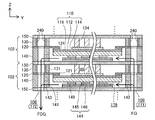
- FIG. 10 shows a cross-sectional configuration of two power generation units 102 adjacent to each other at the same position as the cross section shown in FIG. 4, and FIG. 7 shows adjacent cross sections at the same position as the cross section shown in FIG.
- FIG. 8 shows a cross-sectional configuration of the power generation unit 102 at the position of VIII-VIII in FIG. 6, and
- FIG. 9 shows a cross-sectional configuration of the power generation unit 102 in FIG. 10 shows a cross-sectional configuration of the power generation unit 102 at the position IX
- FIG. 10 shows a cross-sectional configuration of the power generation unit 102 at the position XX in FIG. 6, and FIG.
- a cross-sectional configuration of the power generation unit 102 at the position XI-XI is shown.
- the power generation unit 102 which is the minimum unit of power generation includes a single cell 110, a separator 120, an air electrode side frame 130, an air electrode side current collector 134, and a fuel electrode side frame. 140, a fuel electrode side current collector 144, and a pair of interconnectors 150 constituting the uppermost layer and the lowermost layer of the power generation unit 102.
- the separator 120, the air electrode side frame 130, the fuel electrode side frame 140, and the interconnector 150 around the Z direction holes corresponding to the bolt holes 109 into which the bolts 22 are inserted and functions as manifolds.
- a hole corresponding to the communication hole 108 is formed (see FIGS. 8 to 11).
- the single cell 110 includes an electrolyte layer 112 and an air electrode (cathode) 114 and a fuel electrode (anode) 116 that face each other in the vertical direction (the arrangement direction in which the power generation units 102 are arranged) with the electrolyte layer 112 interposed therebetween.
- the single cell 110 of the present embodiment is a fuel electrode-supported single cell that supports the electrolyte layer 112 and the air electrode 114 with the fuel electrode 116.
- the electrolyte layer 112 is a rectangular flat plate-like member, such as YSZ (yttria stabilized zirconia), ScSZ (scandia stabilized zirconia), SDC (samarium doped ceria), GDC (gadolinium doped ceria), perovskite oxide, etc.
- the solid oxide is formed.
- the air electrode 114 is a rectangular flat plate-shaped member, and is formed of, for example, a perovskite oxide (for example, LSCF (lanthanum strontium cobalt iron oxide), LSM (lanthanum strontium manganese oxide), LNF (lanthanum nickel iron)). ing.
- the fuel electrode 116 is a rectangular flat plate-like member, and is formed of, for example, Ni (nickel), cermet made of Ni and ceramic particles, Ni-based alloy, or the like.
- the single cell 110 (power generation unit 102) of the present embodiment is a solid oxide fuel cell (SOFC) that uses a solid oxide as an electrolyte.
- SOFC solid oxide fuel cell
- the separator 120 is a frame-like member in which a rectangular hole 121 penetrating in the vertical direction is formed near the center, and is made of, for example, metal.
- the peripheral part of the hole 121 in the separator 120 is opposed to the peripheral part of the surface of the electrolyte layer 112 on the air electrode 114 side.
- the separator 120 is bonded to the electrolyte layer 112 (single cell 110) by a bonding portion 124 formed of a brazing material (for example, Ag brazing) disposed in the facing portion.
- the separator 120 divides the air chamber 166 facing the air electrode 114 and the fuel chamber 176 facing the fuel electrode 116, and gas leaks from one electrode side to the other electrode side in the peripheral portion of the single cell 110. It is suppressed.
- the single cell 110 to which the separator 120 is bonded is also referred to as a single cell with a separator.
- the interconnector 150 is a rectangular flat plate-shaped conductive member, and is formed of, for example, ferritic stainless steel.
- the interconnector 150 is disposed so as to face the single cell 110 in the arrangement direction.
- the interconnector 150 ensures electrical continuity between the power generation units 102 and prevents reaction gas from being mixed between the power generation units 102.
- one interconnector 150 is shared by two adjacent power generation units 102. That is, the upper interconnector 150 in a power generation unit 102 is the same member as the lower interconnector 150 in another power generation unit 102 adjacent to the upper side of the power generation unit 102.
- the power generation unit 102 located at the top in the fuel cell stack 100 does not include the upper interconnector 150 and is located at the bottom.
- the power generation unit 102 does not include the lower interconnector 150 (see FIGS. 4 and 5).
- the air electrode side frame 130 is a frame-like member in which a rectangular hole 131 penetrating in the vertical direction is formed near the center.
- an insulator such as mica It is formed by.
- the air electrode side frame 130 is disposed between the separator 120 and the interconnector 150, and is opposed to the peripheral edge of the surface of the separator 120 opposite to the side facing the electrolyte layer 112 and the air electrode 114 of the interconnector 150. In contact with the peripheral edge of the surface on the side to be
- the hole 131 of the air electrode side frame 130 forms an air chamber 166 that faces the air electrode 114.
- the pair of interconnectors 150 included in the power generation unit 102 is electrically insulated by the air electrode side frame 130.
- the air electrode side frame 130 has an oxidant gas supply communication hole 132 communicating the oxidant gas introduction manifold 161 and the air chamber 166, and an oxidant gas communicating the air chamber 166 and the oxidant gas discharge manifold 162.
- a discharge communication hole 133 is formed.
- the fuel electrode side frame 140 is a frame-like member in which a rectangular hole 141 penetrating in the vertical direction is formed near the center, and is formed of, for example, metal. Yes.
- the fuel electrode side frame 140 is disposed between the separator 120 and the interconnector 150, and has a peripheral edge on the surface of the separator 120 facing the electrolyte layer 112 and a surface of the interconnector 150 facing the fuel electrode 116. It is in contact with the peripheral part.
- the hole 141 of the fuel electrode side frame 140 forms a fuel chamber 176 that faces the fuel electrode 116.
- the fuel electrode side frame 140 has a fuel gas supply communication hole 142 that connects the fuel gas introduction manifold 171 and the fuel chamber 176, and a fuel gas discharge communication hole 143 that connects the fuel chamber 176 and the fuel gas discharge manifold 172. And are formed.
- the fuel electrode side frame 140 corresponds to a frame member in the claims.
- the air electrode side current collector 134 is disposed in the air chamber 166.
- the air electrode side current collector 134 is composed of a plurality of substantially quadrangular columnar conductive members arranged at predetermined intervals, and is made of, for example, ferritic stainless steel.
- the air electrode side current collector 134 is brought into contact with the surface of the air electrode 114 opposite to the side facing the electrolyte layer 112 and the surface of the interconnector 150 facing the air electrode 114, whereby the air electrode 114 and the interconnector 150 are electrically connected.
- the air electrode side current collector 134 and the interconnector 150 may be formed as an integral member.
- the fuel electrode side current collector 144 is disposed in the fuel chamber 176.
- the fuel electrode side current collector 144 includes an interconnector facing portion 146, a plurality of electrode facing portions 145, and a connecting portion 147 that connects each electrode facing portion 145 and the interconnector facing portion 146. Or nickel alloy, stainless steel or the like.
- Each electrode facing portion 145 contacts the surface of the fuel electrode 116 opposite to the side facing the electrolyte layer 112, and the interconnector facing portion 146 contacts the surface of the interconnector 150 facing the fuel electrode 116. To do. Therefore, the fuel electrode side current collector 144 electrically connects the fuel electrode 116 and the interconnector 150.
- a spacer 149 made of, for example, mica is disposed between the electrode facing portion 145 and the interconnector facing portion 146. Therefore, the fuel electrode side current collector 144 follows the deformation of the power generation unit 102 due to the temperature cycle or reaction gas pressure fluctuation, and the fuel electrode 116 and the interconnector 150 are electrically connected via the fuel electrode side current collector 144. Maintained well.
- the oxidant gas is connected via a gas pipe (not shown) connected to the branch portion 29 of the gas passage member 27 provided at the position of the oxidant gas introduction manifold 161.
- a gas pipe (not shown) connected to the branch portion 29 of the gas passage member 27 provided at the position of the oxidant gas introduction manifold 161.
- the oxidant gas OG is supplied to the oxidant gas introduction manifold 161 through the branch part 29 of the gas passage member 27 and the hole of the main body part 28, and each power generation unit is supplied from the oxidant gas introduction manifold 161.
- 102 is supplied to the air chamber 166 through the oxidant gas supply communication hole 132. Further, as shown in FIGS.
- the fuel gas is supplied via a gas pipe (not shown) connected to the branch portion 29 of the gas passage member 27 provided at the position of the fuel gas introduction manifold 171.
- a gas pipe (not shown) connected to the branch portion 29 of the gas passage member 27 provided at the position of the fuel gas introduction manifold 171.
- the fuel gas FG is supplied to the fuel gas introduction manifold 171 through the branch portion 29 of the gas passage member 27 and the hole of the main body portion 28, and the fuel of each power generation unit 102 is supplied from the fuel gas introduction manifold 171.
- the fuel is supplied to the fuel chamber 176 through the gas supply communication hole 142.
- each power generation unit 102 When the oxidant gas OG is supplied to the air chamber 166 of each power generation unit 102 and the fuel gas FG is supplied to the fuel chamber 176, power is generated by an electrochemical reaction between the oxidant gas OG and the fuel gas FG in the single cell 110. Is called. This power generation reaction is an exothermic reaction.
- the air electrode 114 of the single cell 110 is electrically connected to one interconnector 150 via the air electrode side current collector 134, and the fuel electrode 116 is connected via the fuel electrode side current collector 144.
- the other interconnector 150 is electrically connected.
- the plurality of power generation units 102 included in the fuel cell stack 100 are electrically connected in series.
- each power generation unit 102 electrical energy generated in each power generation unit 102 is taken out from the end plates 104 and 106 that function as output terminals of the fuel cell stack 100. Since SOFC generates power at a relatively high temperature (for example, 700 ° C. to 1000 ° C.), the fuel cell stack 100 is heated by a heater (after the start-up until the high temperature can be maintained by the heat generated by the power generation. (Not shown).
- the oxidant off-gas OOG that is the oxidant gas OG that has not been used for the power generation reaction in each power generation unit 102 passes through the oxidant gas discharge communication hole 133 from the air chamber 166.
- the gas is discharged to the oxidant gas discharge manifold 162 and further connected to the branch part 29 through the holes of the main body part 28 and the branch part 29 of the gas passage member 27 provided at the position of the oxidant gas discharge manifold 162. It is discharged to the outside of the fuel cell stack 100 through piping (not shown).
- the fuel off-gas FOG that is the fuel gas FG that has not been used for the power generation reaction in each power generation unit 102 passes through the fuel gas discharge communication hole 143 from the fuel chamber 176, as shown in FIGS.
- Gas piping (shown in the figure) connected to the branching portion 29 through the holes of the main body portion 28 and the branching portion 29 of the gas passage member 27 that is discharged to the fuel gas discharge manifold 172 and further provided at the position of the fuel gas discharge manifold 172. Is not discharged to the outside of the fuel cell stack 100.
- the contaminants contained in the bolts 22 are transferred to the respective manifolds. It is possible to avoid the occurrence of a contamination phenomenon that is carried to the fuel chamber 176 and the air chamber 166 by the gas flow in the gas and adheres to the fuel electrode 116 and the air electrode 114 and decreases the reaction speed of the electrodes.
- a difference in deformation amount due to thermal expansion of each bolt 22 occurs due to exposure to gases at different temperatures, the contact pressure of the fuel cell stack 100 varies in the surface direction of the fuel cell stack 100, and the gas flows from the inside of the fuel cell stack 100 to the outside. Can be avoided.
- the air electrode side frame 130 included in each power generation unit 102 in the fuel cell stack 100 functions as a so-called compression seal.
- the air electrode side frame 130 is sandwiched between the separator 120 and the interconnector 150 and is compressed, thereby closely contacting the surfaces of the separator 120 and the interconnector 150.
- a fuel gas introduction manifold 171 and a fuel gas discharge manifold 172 are provided between the separator 120 and the interconnector 150 facing the separator 120 with the air electrode side frame 130 interposed therebetween.
- a glass seal 240 is provided so as to surround each of these.
- the glass seal 240 is connected to the fuel gas FG (from the fuel gas introduction manifold 171 and the fuel gas discharge manifold 172 via the interface between the air electrode side frame 130 and the separator 120 and the interface between the air electrode side frame 130 and the interconnector 150.
- the leakage of the fuel off gas FOG is suppressed.
- the glass seal 240 is an insulator, the provision of the glass seal 240 does not hinder the electrical insulation between the pair of interconnectors 150 included in the power generation unit 102.
- the glass seal 240 is not provided around the oxidant gas introduction manifold 161 and the oxidant gas discharge manifold 162.
- the glass seal 240 corresponds to the second seal portion in the claims.
- FIG. 12 is an explanatory diagram showing the configuration of the gas seal at the position of the fuel electrode side frame 140.
- FIG. 12 shows a part of the cross-sectional configuration of the fuel cell stack 100 at the position XII-XII in FIGS. 1 to 3 and FIGS. 8 to 11.
- a welded portion 230 is formed by laser welding between the fuel electrode side frame 140 and the separator 120 adjacent to the upper side of the fuel electrode side frame 140.
- a welded portion 230 is also formed by welding between the fuel electrode side frame 140 and the interconnector 150 adjacent to the lower side of the fuel electrode side frame 140.
- the welded portion 230 includes an outer periphery welded portion 233 formed along the outer periphery shape of each power generation unit 102.
- the outer periphery welding part 233 is formed along the outer periphery of the power generation unit 102, and each communication hole 108 and each bolt hole 109 formed in each power generation unit 102 exists inside the outer periphery welding part 233.
- a fuel gas FG (or fuel) from the inside to the outside of the fuel cell stack 100 via the interface between the fuel electrode side frame 140 and the separator 120 and the interface between the fuel electrode side frame 140 and the interconnector 150 by the outer periphery welding portion 233.
- Off-gas FOG Off-gas FOG
- the welded portion 230 includes a manifold periphery weld 235 formed so as to surround each of the oxidant gas introduction manifold 161 and the oxidant gas discharge manifold 162.
- the manifold periphery weld 235 By means of the manifold periphery weld 235, the oxidant gas introduction manifold 161 and the oxidant gas discharge manifold 162 are connected via the interface between the fuel electrode side frame 140 and the separator 120 and the interface between the fuel electrode side frame 140 and the interconnector 150. Leakage of the oxidant gas OG (or oxidant off-gas OOG) is suppressed.
- the separator 120 may have a hole or the fuel gas supply Since the communication hole 142 and the fuel gas discharge communication hole 143 may be blocked, it is difficult to weld the members. For this reason, the welded portion 230 is not formed around the fuel gas introduction manifold 171 and the fuel gas discharge manifold 172.
- the welded portion 230 includes a bolt-around welded portion 231 formed so as to surround each bolt hole 109 along the outer peripheral shape of the bolt hole 109.
- the fuel chamber 176, the fuel gas introduction manifold 171, and the fuel gas discharge manifold 172 are connected through the interface between the fuel electrode side frame 140 and the separator 120 and the interface between the fuel electrode side frame 140 and the interconnector 150 by the welding part 231 around the bolt.
- the leakage of the fuel gas FG (or fuel off-gas FOG) from the through hole to the bolt hole 109 is suppressed.
- the bolt circumference welded portion 231 corresponds to the first seal portion in the claims.
- a plurality of manifolds (communication holes 108) extending over the plurality of power generation units 102 are formed in addition to the plurality of bolt holes 109. Further, a welded portion 230 that seals between the separator 120 and the fuel electrode side frame 140 and between the fuel electrode side frame 140 and the interconnector 150 is formed. A bolt periphery weld 231 formed to surround the periphery is included. Therefore, in the fuel cell stack 100 of this embodiment, it is possible to suppress the leakage of the fuel gas FG (or the fuel off-gas FOG) from the fuel gas introduction manifold 171, the fuel gas discharge manifold 172, and the fuel chamber 176 to the bolt hole 109.
- the fuel gas FG or the fuel off-gas FOG
- the gas seal at the position of the welded portion 231 around the bolt is formed by the welded portion 230 that can be expected to have a high sealing performance, and thus gas leakage to the bolt hole 109 is more reliably suppressed. Therefore, it is possible to effectively suppress a decrease in power generation efficiency of the fuel cell stack 100.
- the fuel gas introduction manifold 171 and the fuel gas discharge manifold 172 are disposed between the separator 120 and the interconnector 150 facing the separator 120 with the air electrode side frame 130 interposed therebetween. Since the glass seal 240 is provided so as to surround each of the two, the fuel gas introduction manifold via the interface between the air electrode side frame 130 and the separator 120 and the interface between the air electrode side frame 130 and the interconnector 150 is provided.
- the leakage of the fuel gas FG (or the fuel off-gas FOG) from the fuel gas exhaust manifold 172 or the fuel gas discharge manifold 172 can be suppressed, and the reduction in power generation efficiency of the fuel cell stack 100 can be more effectively suppressed.
- the welded portion 230 includes the outer peripheral welded portion 233 formed along the outer peripheral shape of each power generation unit 102, the interface between the fuel electrode side frame 140 and the separator 120 or the like Leakage of the fuel gas FG (or fuel off-gas FOG) from the inside of the fuel cell stack 100 to the outside via the interface between the fuel electrode side frame 140 and the interconnector 150 is suppressed, and the power generation efficiency of the fuel cell stack 100 is reduced. Can be more effectively suppressed.
- all of the bolt periphery welding part 231, the glass seal 240, and the outer periphery welding part 233 exhibit the sealing function between members by joining between the members to be sealed.
- the welded part 231 around the bolt, the glass seal 240, and the outer periphery welded part 233 are distinguished from those that exhibit a sealing function between members by being sandwiched and compressed between the members to be sealed (so-called compression seals).
- the welded portion 230 is formed both between the fuel electrode side frame 140 and the separator 120 and between the fuel electrode side frame 140 and the interconnector 150. It is good also as being formed only in one of these.
- the welding part 230 is supposed to include the bolt periphery welding part 231, the outer periphery welding part 233, and the manifold periphery welding part 235, the welding part 230 is the outer periphery welding part 233 and the manifold periphery welding part 235. And at least one of them may not be included.
- the welded portion 230 is formed by laser welding, but may be formed by a welding method other than laser welding. Further, a seal configuration other than welding (for example, a glass seal) may be formed in place of the welded portion 230 at the position where the welded portion 230 is formed.
- the outer periphery welding part 233 is formed along the outer periphery shape of each electric power generation unit 102, the outer periphery welding part 233 is not necessarily formed along the outer periphery shape of each electric power generation unit 102.
- the first direction Z direction
- it passes between each manifold 171, 172, 161, 162 and the outer peripheral edge of each power generation unit 102, and all the manifolds 171, 172, 161 , 162 as long as they are continuously formed so as to surround them.
- the glass seals 240 surrounding the fuel gas introduction manifold 171 and the fuel gas discharge manifold 172 are provided.
- the glass seal 240 is formed around the fuel gas introduction manifold 171 and the fuel gas. It may be provided only on one side around the discharge manifold 172. Further, the glass seal 240 may be provided around the oxidant gas introduction manifold 161 and the oxidant gas discharge manifold 162. Further, instead of the glass seal 240, a seal configuration other than the glass seal may be formed at a position where the glass seal 240 is formed.
- the gas seal is secured by welding at the position of the fuel electrode side frame 140.
- the gas seal is secured by welding at the position of the air electrode side frame 130 as well. Good.
- the number of power generation units 102 included in the fuel cell stack 100 is merely an example, and the number of power generation units 102 is appropriately determined according to the output voltage required for the fuel cell stack 100 or the like.
- the nuts 24 are fitted on both sides of the bolt 22, but the bolt 22 has a head, and the nut 24 is fitted only on the opposite side of the head of the bolt 22. Also good.
- the end plates 104 and 106 function as output terminals.
- separate members for example, the end plate 104 connected to the end plates 104 and 106, respectively.
- 106 and the power generation unit 102 may function as output terminals.
- one interconnector 150 is shared by two adjacent power generation units 102.
- Two power generation units 102 may be provided with respective interconnectors 150.
- the upper interconnector 150 of the uppermost power generation unit 102 in the fuel cell stack 100 and the lower interconnector 150 of the lowermost power generation unit 102 are omitted. These interconnectors 150 may be provided without being omitted.
- the fuel electrode side current collector 144 may have the same configuration as the air electrode side current collector 134, and the fuel electrode side current collector 144 and the adjacent interconnector 150 are an integral member. It may be. Further, the fuel electrode side frame 140 instead of the air electrode side frame 130 may be an insulator. The air electrode side frame 130 and the fuel electrode side frame 140 may have a multilayer structure.
- each member in the above embodiment is merely an example, and each member may be formed of other materials.
- the city gas is reformed to obtain the hydrogen-rich fuel gas FG
- the fuel gas FG may be obtained from other raw materials such as LP gas, kerosene, methanol, gasoline, Pure hydrogen may be used as the fuel gas FG.
- a reaction preventing layer formed of, for example, ceria is provided between the electrolyte layer 112 and the air electrode 114 so that zirconium or the like in the electrolyte layer 112 reacts with strontium or the like in the air electrode 114.
- An increase in electrical resistance between the electrolyte layer 112 and the air electrode 114 may be suppressed.
- the solid oxide fuel cell has been described as an example.
- the present invention can be applied to a solid polymer fuel cell (PEFC), a phosphoric acid fuel cell (PAFC), a molten carbonate type. It can also be applied to other types of fuel cells such as fuel cells (MCFC).
- PEFC solid polymer fuel cell
- PAFC phosphoric acid fuel cell
- MCFC fuel cells
Landscapes
- Life Sciences & Earth Sciences (AREA)
- Engineering & Computer Science (AREA)
- Manufacturing & Machinery (AREA)
- Sustainable Development (AREA)
- Sustainable Energy (AREA)
- Chemical & Material Sciences (AREA)
- Chemical Kinetics & Catalysis (AREA)
- Electrochemistry (AREA)
- General Chemical & Material Sciences (AREA)
- Fuel Cell (AREA)
Abstract
ガス流路や燃料室または空気室からボルト孔へガスがリークすることを抑制する。 燃料電池スタックは、複数の発電単位と、複数のボルト孔のそれぞれに挿入されたボルトとを備え、各ボルトで締結される。各発電単位は、単セルと、金属製のインターコネクタと、空気室と燃料室とを区画する金属製のセパレータと、セパレータとインターコネクタとの間に配置され、燃料室または空気室を構成する貫通孔が形成された金属製のフレーム部材とを含む。燃料電池スタックには、複数のボルト孔とは別に、複数の発電単位にわたって延びる複数のガス流路が形成されている。燃料電池スタックは、セパレータとフレーム部材との間とフレーム部材とインターコネクタとの間との少なくとも一方をシールする第1のシール部を備え、第1のシール部は各ボルト孔の周りを取り囲むように形成されている。
Description
本明細書によって開示される技術は、燃料電池スタックに関する。
固体酸化物形燃料電池(以下、「SOFC」ともいう)は、一般に、所定の方向(以下、「配列方向」ともいう)に並べて配置された複数の発電単位を備える燃料電池スタックの形態で利用される。発電単位は、発電の最小単位であり、電解質層と電解質層を挟んで配列方向に互いに対向する空気極および燃料極とを含む。燃料電池スタックには、複数の発電単位にわたって配列方向に延びる複数のボルト孔が形成されており、複数のボルト孔のそれぞれに挿入されたボルトによって締結される。
また、燃料電池スタックには、複数の発電単位にわたって延びる複数のガス流路(「マニホールド」とも呼ばれる)が形成されている。各ガス流路を介して、各発電単位の燃料極に面する燃料室および空気極に面する空気室に、それぞれ燃料ガスおよび酸化剤ガスが供給され、また、各発電単位の燃料室および空気室から、それぞれ燃料オフガスおよび酸化剤オフガスが排出される。
上述した複数のボルト孔を上述した複数のガス流路としても利用する燃料電池スタックの形態が知られている。この形態では、ボルト孔の内周面とボルト孔に挿入されたボルトの軸部の外周面との間に形成された空間や、ボルトの軸部の内部に形成された空間が、ガス流路として利用される。この形態では、ボルトに含まれる汚染物質が、ガス流路におけるガス流れによって燃料室や空気室に運ばれ、燃料極や空気極に付着して電極の反応速度が低下する汚染現象を引き起こすおそれがある。また、この形態では、各ガス流路を流れるガスの温度が互いに異なる場合に、各ボルトは互いに異なる温度のガスにさらされるため、各ボルトの熱膨張による変形量に差が生じ、燃料電池スタックの面方向(配列方向に直交する方向)において燃料電池スタックを配列方向に押さえる圧力(以下、「接圧」ともいう)がばらつき、燃料電池スタックの内部から外部にガスが漏洩するおそれがある。
他方、複数のボルト孔とは別に複数のガス流路が形成された燃料電池スタックの形態が知られている(例えば特許文献1参照)。この形態では、上述した汚染現象の発生や接圧のばらつきを抑制することができる。
複数のボルト孔とは別に複数のガス流路が形成された燃料電池スタックでは、燃料室や燃料ガス用のマニホールドから各ボルト孔への燃料ガスの内部リークが発生するおそれがある。具体的には、各発電単位が、金属製のインターコネクタと、燃料室と空気室とを区画する金属製のセパレータと、セパレータとインターコネクタとの間に配置され、燃料室を構成する貫通孔が形成された金属製のフレーム部材とを備える構成である場合に、セパレータとフレーム部材との間やフレーム部材とインターコネクタとの間を通って、ボルト孔へ燃料ガスがリークするおそれがある。ボルト孔への燃料ガスのリークが発生すると、燃料電池スタックの効率が低下するため、好ましくない。上記従来の技術では、金属箔により形成されたパッキンがフレーム部材とインターコネクタとの間に配置されているが、この構成では、ボルト孔への燃料ガスのリークを十分に抑制できない。
なお、このような課題は、燃料極側に限らず、空気極側にも共通の課題である。すなわち、各発電単位が、金属製のインターコネクタと、金属製のセパレータと、セパレータとインターコネクタとの間に配置され、空気室を構成する貫通孔が形成された金属製のフレーム部材とを備える構成である場合に、セパレータとフレーム部材との間やフレーム部材とインターコネクタとの間を通って、ボルト孔へ酸化剤ガスがリークするおそれがある。また、このような課題は、SOFCに限らず、他のタイプの燃料電池にも共通の課題である。
本明細書では、上述した課題の少なくとも一部を解決することが可能な技術を開示する。
本明細書に開示される技術は、例えば、以下の形態として実現することが可能である。
(1)本明細書に開示される燃料電池スタックは、第1の方向に並べて配置された複数の発電単位と、前記複数の発電単位にわたって前記第1の方向に延びる複数のボルト孔のそれぞれに挿入されたボルトとを備え、各前記ボルトで締結された燃料電池スタックにおいて、各前記発電単位は、電解質層と前記電解質層を挟んで前記第1の方向に互いに対向する空気極および燃料極とを含む単セルと、前記単セルと前記第1の方向に対向する金属製のインターコネクタと、貫通孔が形成され、前記貫通孔を取り囲む部分が前記単セルの周縁部と接合され、前記空気極に面する空気室と前記燃料極に面する燃料室とを区画する金属製のセパレータと、前記セパレータと前記インターコネクタとの間に配置され、前記燃料室または前記空気室を構成する貫通孔が形成された金属製のフレーム部材と、を含み、前記燃料電池スタックには、前記複数のボルト孔とは別に、前記複数の発電単位にわたって延びる複数のガス流路が形成されており、前記セパレータと前記フレーム部材との間と、前記フレーム部材と前記インターコネクタとの間と、の少なくとも一方を接合してシールする第1のシール部を備え、前記第1のシール部は、各前記ボルト孔の周りを取り囲むように形成されていることを特徴とする。本燃料電池スタックによれば、第1のシール部が各ボルト孔の周りを取り囲むように形成されているため、ガス流路や燃料室または空気室からボルト孔へガスがリークすることを抑制することができ、燃料電池スタックの発電効率の低下を抑制することができる。
(2)上記燃料電池スタックにおいて、前記第1のシール部は、前記セパレータと前記フレーム部材との間と、前記フレーム部材と前記インターコネクタとの間と、の両方をシールすることを特徴とする構成としてもよい。本燃料電池スタックによれば、第1のシール部が、セパレータとフレーム部材との間とフレーム部材とインターコネクタとの間との両方をシールするように形成されているため、ガス流路や燃料室または空気室からボルト孔へガスがリークすることを抑制することができ、燃料電池スタックの発電効率の低下を効果的に抑制することができる。
(3)上記燃料電池スタックにおいて、一の前記発電単位が備える前記セパレータと、前記第1の方向において前記一の発電単位の隣に位置する他の前記発電単位が備える前記インターコネクタである他インターコネクタと、の間において、少なくとも1つの前記ガス流路を取り囲むように接合してシールする第2のシール部が形成されていることを特徴とする構成としてもよい。本燃料電池スタックによれば、本来ガスが流れるべきガス流路からガスがリークすることを効果的に抑制することができ、燃料電池スタックの発電効率の低下をさらに効果的に抑制することができる。
(4)上記燃料電池スタックにおいて、 前記セパレータと前記フレーム部材との間と、前記フレーム部材と前記インターコネクタとの間と、の少なくとも一方を接合してシールする第3のシール部を備え、前記第3のシール部は、前記第1の方向視で、前記複数のガス流路のそれぞれと各前記発電単位の外周縁との間を通り、かつ、前記複数のガス流路を取り囲むように連続して形成されていることを特徴とする構成としてもよい。本燃料電池スタックによれば、第3のシール部が複数のガス流路を取り囲むように連続して形成されているため、本来ガスが流れるべき複数のガス流路から燃料電池スタックの外部へガスがリークすることを抑制することができ、燃料電池スタックの発電効率の低下をさらに効果的に抑制することができる。
(5)上記燃料電池スタックにおいて、前記第3のシール部は、各前記発電単位の外周形状に沿って形成されていることを特徴とする構成としてもよい。本燃料電池スタックによれば、第3のシール部が各発電単位の外周形状に沿って形成されているため、本来ガスが流れるべきガス流路や燃料室または空気室から燃料電池スタックの外部へガスがリークすることを抑制することができ、燃料電池スタックの発電効率の低下をさらに効果的に抑制することができる。
(6)上記燃料電池スタックにおいて、前記第1のシール部は、溶接部であることを特徴とする構成としてもよい。本燃料電池スタックによれば、第1のシール部が、高いシール性能が期待できる溶接部により形成されるため、ガス流路や燃料室または空気室からボルト孔へガスがリークすることをより確実に抑制することができ、燃料電池スタックの発電効率の低下をさらに効果的に抑制することができる。
なお、本明細書に開示される技術は、種々の形態で実現することが可能であり、例えば、燃料電池スタック、燃料電池スタックを備える発電モジュール、発電モジュールを備える燃料電池システム等の形態で実現することが可能である。
A.実施形態:
A-1.構成:
(燃料電池スタック100の構成)
図1から図5は、本実施形態における燃料電池スタック100の構成を概略的に示す説明図である。図1には、燃料電池スタック100の外観構成が示されており、図2には、燃料電池スタック100の上側の平面構成が示されており、図3には、燃料電池スタック100の下側の平面構成が示されており、図4には、図1から図3のIV-IVの位置における燃料電池スタック100の断面構成が示されており、図5には、図1から図3のV-Vの位置における燃料電池スタック100の断面構成が示されている。各図には、方向を特定するための互いに直交するXYZ軸が示されている。本明細書では、便宜的に、Z軸正方向を上方向と呼び、Z軸負方向を下方向と呼ぶものとするが、燃料電池スタック100は実際にはそのような向きとは異なる向きで設置されてもよい。図6以降についても同様である。
A-1.構成:
(燃料電池スタック100の構成)
図1から図5は、本実施形態における燃料電池スタック100の構成を概略的に示す説明図である。図1には、燃料電池スタック100の外観構成が示されており、図2には、燃料電池スタック100の上側の平面構成が示されており、図3には、燃料電池スタック100の下側の平面構成が示されており、図4には、図1から図3のIV-IVの位置における燃料電池スタック100の断面構成が示されており、図5には、図1から図3のV-Vの位置における燃料電池スタック100の断面構成が示されている。各図には、方向を特定するための互いに直交するXYZ軸が示されている。本明細書では、便宜的に、Z軸正方向を上方向と呼び、Z軸負方向を下方向と呼ぶものとするが、燃料電池スタック100は実際にはそのような向きとは異なる向きで設置されてもよい。図6以降についても同様である。
燃料電池スタック100は、複数の(本実施形態では7つの)発電単位102と、一対のエンドプレート104,106とを備える。7つの発電単位102は、所定の配列方向(本実施形態では上下方向)に並べて配置されている。一対のエンドプレート104,106は、7つの発電単位102を上下から挟むように配置されている。なお、上記配列方向(上下方向)は、特許請求の範囲における第1の方向に相当する。
図1に示すように、各発電単位102およびエンドプレート104,106のZ方向回りの外周の4つの角部には、上下方向に貫通する孔が形成されており、各層に形成され互いに対応する孔同士が上下方向に連通して、一方のエンドプレート104から他方のエンドプレート106にわたって上下方向に延びるボルト孔109を構成している。各ボルト孔109にはボルト22が挿入されており、ボルト22とボルト22の両側に嵌められたナット24とによって、燃料電池スタック100は締結されている。
また、図1、図4および図5に示すように、各発電単位102および下側のエンドプレート106のZ方向回りの外周辺の中点付近には、上下方向に貫通する孔が形成されており、各層に形成され互いに対応する孔同士が上下方向に連通して、各発電単位102およびエンドプレート106にわたって上下方向に延びる連通孔108を構成している。
図1、図2および図4に示すように、燃料電池スタック100のZ方向回りの外周における1つの辺(Y軸に平行な2つの辺の内のX軸正方向側の辺)の中点付近に位置する連通孔108は、燃料電池スタック100の外部から酸化剤ガスOGが導入され、その酸化剤ガスOGを各発電単位102に供給するガス流路である酸化剤ガス導入マニホールド161として機能し、該辺の反対側の辺(Y軸に平行な2つの辺の内のX軸負方向側の辺)の中点付近に位置する連通孔108は、各発電単位102から排出された未反応の酸化剤ガスOGである酸化剤オフガスOOGを燃料電池スタック100の外部へと排出するガス流路である酸化剤ガス排出マニホールド162として機能する。なお、本実施形態では、酸化剤ガスOGとして、例えば空気が使用される。
また、図1、図2および図5に示すように、燃料電池スタック100のZ方向回りの外周における1つの辺(X軸に平行な2つの辺の内のY軸正方向側の辺)の中点付近に位置する連通孔108は、燃料電池スタック100の外部から燃料ガスFGが導入され、その燃料ガスFGを各発電単位102に供給するガス流路である燃料ガス導入マニホールド171として機能し、該辺の反対側の辺(X軸に平行な2つの辺の内のY軸負方向側の辺)の中点付近に位置する連通孔108は、各発電単位102から排出された未反応の燃料ガスFGである燃料オフガスFOGを燃料電池スタック100の外部へと排出するガス流路である燃料ガス排出マニホールド172として機能する。なお、本実施形態では、燃料ガスFGとして、例えば都市ガスを改質した水素リッチなガスが使用される。
図1および図3から図5に示すように、燃料電池スタック100には、4つのガス通路部材27が設けられている。各ガス通路部材27は、中空筒状の本体部28と、本体部28の側面から分岐した中空筒状の分岐部29とを有している。分岐部29の孔は本体部28の孔と連通している。各ガス通路部材27の分岐部29には、ガス配管(図示せず)が接続される。図4に示すように、酸化剤ガス導入マニホールド161の位置に配置されたガス通路部材27の本体部28の孔は、酸化剤ガス導入マニホールド161に連通しており、酸化剤ガス排出マニホールド162の位置に配置されたガス通路部材27の本体部28の孔は、酸化剤ガス排出マニホールド162に連通している。また、図5に示すように、燃料ガス導入マニホールド171の位置に配置されたガス通路部材27の本体部28の孔は、燃料ガス導入マニホールド171に連通しており、燃料ガス排出マニホールド172の位置に配置されたガス通路部材27の本体部28の孔は、燃料ガス排出マニホールド172に連通している。なお、各ガス通路部材27とエンドプレート106の表面との間には、絶縁シート26が介在している。絶縁シート26は、例えばマイカシートや、セラミック繊維シート、セラミック圧粉シート、ガラスシート、ガラスセラミック複合剤等により構成される。
(エンドプレート104,106の構成)
一対のエンドプレート104,106は、矩形の平板形状の導電性部材であり、例えばステンレスにより形成されている。一方のエンドプレート104は、最も上に位置する発電単位102の上側に配置され、他方のエンドプレート106は、最も下に位置する発電単位102の下側に配置されている。一対のエンドプレート104,106によって複数の発電単位102が押圧された状態で挟持されている。上側のエンドプレート104は、燃料電池スタック100のプラス側の出力端子として機能し、下側のエンドプレート106は、燃料電池スタック100のマイナス側の出力端子として機能する。
一対のエンドプレート104,106は、矩形の平板形状の導電性部材であり、例えばステンレスにより形成されている。一方のエンドプレート104は、最も上に位置する発電単位102の上側に配置され、他方のエンドプレート106は、最も下に位置する発電単位102の下側に配置されている。一対のエンドプレート104,106によって複数の発電単位102が押圧された状態で挟持されている。上側のエンドプレート104は、燃料電池スタック100のプラス側の出力端子として機能し、下側のエンドプレート106は、燃料電池スタック100のマイナス側の出力端子として機能する。
(発電単位102の構成)
図6から図11は、発電単位102の詳細構成を示す説明図である。図6には、図4に示す断面と同一の位置における互いに隣接する2つの発電単位102の断面構成が示されており、図7には、図5に示す断面と同一の位置における互いに隣接する2つの発電単位102の断面構成が示されており、図8には、図6のVIII-VIIIの位置における発電単位102の断面構成が示されており、図9には、図6のIX-IXの位置における発電単位102の断面構成が示されており、図10には、図6のX-Xの位置における発電単位102の断面構成が示されており、図11には、図6のXI-XIの位置における発電単位102の断面構成が示されている。
図6から図11は、発電単位102の詳細構成を示す説明図である。図6には、図4に示す断面と同一の位置における互いに隣接する2つの発電単位102の断面構成が示されており、図7には、図5に示す断面と同一の位置における互いに隣接する2つの発電単位102の断面構成が示されており、図8には、図6のVIII-VIIIの位置における発電単位102の断面構成が示されており、図9には、図6のIX-IXの位置における発電単位102の断面構成が示されており、図10には、図6のX-Xの位置における発電単位102の断面構成が示されており、図11には、図6のXI-XIの位置における発電単位102の断面構成が示されている。
図6および図7に示すように、発電の最小単位である発電単位102は、単セル110と、セパレータ120と、空気極側フレーム130と、空気極側集電体134と、燃料極側フレーム140と、燃料極側集電体144と、発電単位102の最上層および最下層を構成する一対のインターコネクタ150とを備えている。セパレータ120、空気極側フレーム130、燃料極側フレーム140、インターコネクタ150におけるZ方向回りの周縁部には、上述したボルト22が挿入されるボルト孔109に対応する孔や、各マニホールドして機能する連通孔108に対応する孔が形成されている(図8から図11参照)。
単セル110は、電解質層112と、電解質層112を挟んで上下方向(発電単位102が並ぶ配列方向)に互いに対向する空気極(カソード)114および燃料極(アノード)116とを備える。なお、本実施形態の単セル110は、燃料極116で電解質層112および空気極114を支持する燃料極支持形の単セルである。
電解質層112は、矩形の平板形状部材であり、例えば、YSZ(イットリア安定化ジルコニア)、ScSZ(スカンジア安定化ジルコニア)、SDC(サマリウムドープセリア)、GDC(ガドリニウムドープセリア)、ペロブスカイト型酸化物等の固体酸化物により形成されている。空気極114は、矩形の平板形状部材であり、例えば、ペロブスカイト型酸化物(例えばLSCF(ランタンストロンチウムコバルト鉄酸化物)、LSM(ランタンストロンチウムマンガン酸化物)、LNF(ランタンニッケル鉄))により形成されている。燃料極116は、矩形の平板形状部材であり、例えば、Ni(ニッケル)、Niとセラミック粒子からなるサーメット、Ni基合金等により形成されている。このように、本実施形態の単セル110(発電単位102)は、電解質として固体酸化物を用いる固体酸化物形燃料電池(SOFC)である。
図6から図8に示すように、セパレータ120は、中央付近に上下方向に貫通する矩形の孔121が形成されたフレーム状の部材であり、例えば、金属により形成されている。セパレータ120における孔121の周囲部分は、電解質層112における空気極114の側の表面の周縁部に対向している。セパレータ120は、その対向した部分に配置されたロウ材(例えばAgロウ)により形成された接合部124により、電解質層112(単セル110)と接合されている。セパレータ120により、空気極114に面する空気室166と燃料極116に面する燃料室176とが区画され、単セル110の周縁部における一方の電極側から他方の電極側へのガスのリークが抑制される。なお、セパレータ120が接合された単セル110をセパレータ付き単セルともいう。
図6、図7および図9に示すように、インターコネクタ150は、矩形の平板形状の導電性部材であり、例えばフェライト系ステンレスにより形成されている。インターコネクタ150は、単セル110に対して配列方向に対向するように配置されている。インターコネクタ150は、発電単位102間の電気的導通を確保すると共に、発電単位102間での反応ガスの混合を防止する。なお、本実施形態では、2つの発電単位102が隣接して配置されている場合、1つのインターコネクタ150は、隣接する2つの発電単位102に共有されている。すなわち、ある発電単位102における上側のインターコネクタ150は、その発電単位102の上側に隣接する他の発電単位102における下側のインターコネクタ150と同一部材である。また、燃料電池スタック100は一対のエンドプレート104,106を備えているため、燃料電池スタック100において最も上に位置する発電単位102は上側のインターコネクタ150を備えておらず、最も下に位置する発電単位102は下側のインターコネクタ150を備えていない(図4および図5参照)。
図6、図7および図10に示すように、空気極側フレーム130は、中央付近に上下方向に貫通する矩形の孔131が形成されたフレーム状の部材であり、例えば、マイカ等の絶縁体により形成されている。空気極側フレーム130は、セパレータ120とインターコネクタ150との間に配置され、セパレータ120における電解質層112に対向する側とは反対側の表面の周縁部と、インターコネクタ150における空気極114に対向する側の表面の周縁部とに接触している。空気極側フレーム130の孔131は、空気極114に面する空気室166を構成する。また、空気極側フレーム130によって、発電単位102に含まれる一対のインターコネクタ150間が電気的に絶縁される。また、空気極側フレーム130には、酸化剤ガス導入マニホールド161と空気室166とを連通する酸化剤ガス供給連通孔132と、空気室166と酸化剤ガス排出マニホールド162とを連通する酸化剤ガス排出連通孔133とが形成されている。
図6、図7および図11に示すように、燃料極側フレーム140は、中央付近に上下方向に貫通する矩形の孔141が形成されたフレーム状の部材であり、例えば、金属により形成されている。燃料極側フレーム140は、セパレータ120とインターコネクタ150との間に配置され、セパレータ120における電解質層112に対向する側の表面の周縁部と、インターコネクタ150における燃料極116に対向する側の表面の周縁部とに接触している。燃料極側フレーム140の孔141は、燃料極116に面する燃料室176を構成する。また、燃料極側フレーム140には、燃料ガス導入マニホールド171と燃料室176とを連通する燃料ガス供給連通孔142と、燃料室176と燃料ガス排出マニホールド172とを連通する燃料ガス排出連通孔143とが形成されている。本実施形態では、燃料極側フレーム140が特許請求の範囲におけるフレーム部材に相当する。
図6、図7および図10に示すように、空気極側集電体134は、空気室166内に配置されている。空気極側集電体134は、所定の間隔をあけて並べられた複数の略四角柱状の導電性部材から構成されており、例えば、フェライト系ステンレスにより形成されている。空気極側集電体134は、空気極114における電解質層112に対向する側とは反対側の表面と、インターコネクタ150における空気極114に対向する側の表面とに接触することにより、空気極114とインターコネクタ150とを電気的に接続する。なお、空気極側集電体134とインターコネクタ150とが一体の部材として形成されていてもよい。
図6、図7および図11に示すように、燃料極側集電体144は、燃料室176内に配置されている。燃料極側集電体144は、インターコネクタ対向部146と、複数の電極対向部145と、各電極対向部145とインターコネクタ対向部146とをつなぐ連接部147とを備えており、例えば、ニッケルやニッケル合金、ステンレス等により形成されている。各電極対向部145は、燃料極116における電解質層112に対向する側とは反対側の表面に接触し、インターコネクタ対向部146は、インターコネクタ150における燃料極116に対向する側の表面に接触する。そのため、燃料極側集電体144は、燃料極116とインターコネクタ150とを電気的に接続する。なお、電極対向部145とインターコネクタ対向部146との間には、例えばマイカにより形成されたスペーサー149が配置されている。そのため、燃料極側集電体144が温度サイクルや反応ガス圧力変動による発電単位102の変形に追随し、燃料極側集電体144を介した燃料極116とインターコネクタ150との電気的接続が良好に維持される。
A-2.燃料電池スタック100の動作:
図4、図6および図10に示すように、酸化剤ガス導入マニホールド161の位置に設けられたガス通路部材27の分岐部29に接続されたガス配管(図示せず)を介して酸化剤ガスOGが供給されると、酸化剤ガスOGは、ガス通路部材27の分岐部29および本体部28の孔を介して酸化剤ガス導入マニホールド161に供給され、酸化剤ガス導入マニホールド161から各発電単位102の酸化剤ガス供給連通孔132を介して、空気室166に供給される。また、図5、図7および図11に示すように、燃料ガス導入マニホールド171の位置に設けられたガス通路部材27の分岐部29に接続されたガス配管(図示せず)を介して燃料ガスFGが供給されると、燃料ガスFGは、ガス通路部材27の分岐部29および本体部28の孔を介して燃料ガス導入マニホールド171に供給され、燃料ガス導入マニホールド171から各発電単位102の燃料ガス供給連通孔142を介して、燃料室176に供給される。
図4、図6および図10に示すように、酸化剤ガス導入マニホールド161の位置に設けられたガス通路部材27の分岐部29に接続されたガス配管(図示せず)を介して酸化剤ガスOGが供給されると、酸化剤ガスOGは、ガス通路部材27の分岐部29および本体部28の孔を介して酸化剤ガス導入マニホールド161に供給され、酸化剤ガス導入マニホールド161から各発電単位102の酸化剤ガス供給連通孔132を介して、空気室166に供給される。また、図5、図7および図11に示すように、燃料ガス導入マニホールド171の位置に設けられたガス通路部材27の分岐部29に接続されたガス配管(図示せず)を介して燃料ガスFGが供給されると、燃料ガスFGは、ガス通路部材27の分岐部29および本体部28の孔を介して燃料ガス導入マニホールド171に供給され、燃料ガス導入マニホールド171から各発電単位102の燃料ガス供給連通孔142を介して、燃料室176に供給される。
各発電単位102の空気室166に酸化剤ガスOGが供給され、燃料室176に燃料ガスFGが供給されると、単セル110において酸化剤ガスOGおよび燃料ガスFGの電気化学反応による発電が行われる。この発電反応は発熱反応である。各発電単位102において、単セル110の空気極114は空気極側集電体134を介して一方のインターコネクタ150に電気的に接続され、燃料極116は燃料極側集電体144を介して他方のインターコネクタ150に電気的に接続されている。また、燃料電池スタック100に含まれる複数の発電単位102は、電気的に直列に接続されている。そのため、燃料電池スタック100の出力端子として機能するエンドプレート104,106から、各発電単位102において生成された電気エネルギーが取り出される。なお、SOFCは、比較的高温(例えば700℃から1000℃)で発電が行われることから、起動後、発電により発生する熱で高温が維持できる状態になるまで、燃料電池スタック100が加熱器(図示せず)により加熱されてもよい。
各発電単位102において発電反応に利用されなかった酸化剤ガスOGである酸化剤オフガスOOGは、図4、図6および図10に示すように、空気室166から酸化剤ガス排出連通孔133を介して酸化剤ガス排出マニホールド162に排出され、さらに酸化剤ガス排出マニホールド162の位置に設けられたガス通路部材27の本体部28および分岐部29の孔を経て、当該分岐部29に接続されたガス配管(図示せず)を介して燃料電池スタック100の外部に排出される。また、各発電単位102において発電反応に利用されなかった燃料ガスFGである燃料オフガスFOGは、図5、図7および図11に示すように、燃料室176から燃料ガス排出連通孔143を介して燃料ガス排出マニホールド172に排出され、さらに燃料ガス排出マニホールド172の位置に設けられたガス通路部材27の本体部28および分岐部29の孔を経て、当該分岐部29に接続されたガス配管(図示しない)を介して燃料電池スタック100の外部に排出される。
なお、本実施形態の燃料電池スタック100では、上述したように、複数のボルト孔109とは別に複数のマニホールド(連通孔108)が形成されているため、ボルト22に含まれる汚染物質が各マニホールドにおけるガス流れによって燃料室176や空気室166に運ばれ、燃料極116や空気極114に付着して電極の反応速度が低下する汚染現象の発生を回避することができると共に、各ボルト22が互いに異なる温度のガスにさらされて各ボルト22の熱膨張による変形量に差が生じ、燃料電池スタック100の面方向において燃料電池スタック100の接圧がばらつき、燃料電池スタック100の内部から外部にガスが漏洩する事態の発生を回避することができる。
A-3.燃料電池スタック100におけるガスシール:
燃料電池スタック100において、燃料ガスや酸化剤ガスのリークが発生すると、燃料電池スタックの効率が低下するため、好ましくない。そのため、燃料電池スタック100には、高いガスシール性が求められる。以下、燃料電池スタック100におけるガスシールについて説明する。
燃料電池スタック100において、燃料ガスや酸化剤ガスのリークが発生すると、燃料電池スタックの効率が低下するため、好ましくない。そのため、燃料電池スタック100には、高いガスシール性が求められる。以下、燃料電池スタック100におけるガスシールについて説明する。
燃料電池スタック100における各発電単位102に含まれる空気極側フレーム130(図10)は、いわゆるコンプレッションシールとして機能する。すなわち、空気極側フレーム130は、セパレータ120とインターコネクタ150との間に挟まれて圧縮されることにより、セパレータ120およびインターコネクタ150の表面に密着し、空気極側フレーム130とセパレータ120との界面や空気極側フレーム130とインターコネクタ150との界面を介した、空気室166や酸化剤ガス導入マニホールド161、酸化剤ガス排出マニホールド162からの酸化剤ガスOG(または酸化剤オフガスOOG)のリークを抑制する。
また、図7および図10に示すように、セパレータ120と、空気極側フレーム130を挟んで当該セパレータ120と対向するインターコネクタ150との間において、燃料ガス導入マニホールド171と燃料ガス排出マニホールド172とのそれぞれの周りを取り囲むようにガラスシール240が設けられている。ガラスシール240は、空気極側フレーム130とセパレータ120との界面や空気極側フレーム130とインターコネクタ150との界面を介した、燃料ガス導入マニホールド171や燃料ガス排出マニホールド172からの燃料ガスFG(または燃料オフガスFOG)のリークを抑制する。なお、ガラスシール240は絶縁体であるため、ガラスシール240を設けることによって発電単位102に含まれる一対のインターコネクタ150間の電気的絶縁が阻害されることはない。また、本実施形態では、ガラスシール240は、酸化剤ガス導入マニホールド161および酸化剤ガス排出マニホールド162の周囲には設けられていない。ガラスシール240は、特許請求の範囲における第2のシール部に相当する。
一方、燃料電池スタック100における各発電単位102に含まれる燃料極側フレーム140の位置では、溶接によりガスシールが確保されている。図12は、燃料極側フレーム140の位置のガスシールの構成を示す説明図である。図12には、図1から図3および図8から図11におけるXII-XIIの位置における燃料電池スタック100の断面構成の一部が示されている。
図12に示すように、燃料極側フレーム140とその燃料極側フレーム140の上側に隣接するセパレータ120との間には、レーザ溶接によって溶接部230が形成されている。また、燃料極側フレーム140とその燃料極側フレーム140の下側に隣接するインターコネクタ150との間にも、溶接によって溶接部230が形成されている。
図8、図9および図11には、溶接部230が形成された位置が破線で示されている。図8、図9、図11および図12に示すように、溶接部230は、各発電単位102の外周形状に沿って形成された外周溶接部233を含む。外周溶接部233は、発電単位102の外周に沿うように形成されており、各発電単位102に形成された各連通孔108や各ボルト孔109は、外周溶接部233の内側に存在する。外周溶接部233により、燃料極側フレーム140とセパレータ120との界面や燃料極側フレーム140とインターコネクタ150との界面を介した、燃料電池スタック100の内部から外部への燃料ガスFG(または燃料オフガスFOG)のリークが抑制される。外周溶接部233は、特許請求の範囲における第3のシール部に相当する。
また、溶接部230は、酸化剤ガス導入マニホールド161と酸化剤ガス排出マニホールド162とのそれぞれの周りを取り囲むように形成されたマニホールド周り溶接部235を含む。マニホールド周り溶接部235により、燃料極側フレーム140とセパレータ120との界面や燃料極側フレーム140とインターコネクタ150との界面を介した、酸化剤ガス導入マニホールド161や酸化剤ガス排出マニホールド162からの酸化剤ガスOG(または酸化剤オフガスOOG)のリークが抑制される。なお、燃料ガス導入マニホールド171や燃料ガス排出マニホールド172の周りについては、燃料ガス供給連通孔142や燃料ガス排出連通孔143の部分を溶接しようとすると、セパレータ120に穴があいたり、燃料ガス供給連通孔142や燃料ガス排出連通孔143を塞いでしまったりするおそれがあるため、部材同士を溶接することが難しい。このため、燃料ガス導入マニホールド171や燃料ガス排出マニホールド172の周りについては、溶接部230は形成されていない。
さらに、溶接部230は、各ボルト孔109の周りをボルト孔109の外周形状に沿って取り囲むように形成されたボルト周り溶接部231を含む。ボルト周り溶接部231により、燃料極側フレーム140とセパレータ120との界面や燃料極側フレーム140とインターコネクタ150との界面を介した、燃料室176や燃料ガス導入マニホールド171、燃料ガス排出マニホールド172からボルト孔109への燃料ガスFG(または燃料オフガスFOG)のリークが抑制される。ボルト周り溶接部231は、特許請求の範囲における第1のシール部に相当する。
このように、本実施形態の燃料電池スタック100には、複数のボルト孔109とは別に、複数の発電単位102にわたって延びる複数のマニホールド(連通孔108)が形成されている。また、セパレータ120と燃料極側フレーム140との間、および、燃料極側フレーム140とインターコネクタ150との間をシールする溶接部230が形成されており、溶接部230は、各ボルト孔109の周りを取り囲むように形成されたボルト周り溶接部231を含む。そのため、本実施形態の燃料電池スタック100では、燃料ガス導入マニホールド171や燃料ガス排出マニホールド172、燃料室176からボルト孔109へ燃料ガスFG(または燃料オフガスFOG)がリークすることを抑制することができ、燃料電池スタック100の発電効率の低下を抑制することができる。なお、本実施形態の燃料電池スタック100では、ボルト周り溶接部231の位置におけるガスシールが、高いシール性能が期待できる溶接部230により形成されるため、ボルト孔109へのガスリークをより確実に抑制することができ、燃料電池スタック100の発電効率の低下を効果的に抑制することができる。
また、本実施形態の燃料電池スタック100では、セパレータ120と、空気極側フレーム130を挟んで当該セパレータ120と対向するインターコネクタ150との間において、燃料ガス導入マニホールド171と燃料ガス排出マニホールド172とのそれぞれの周りを取り囲むようにガラスシール240が設けられているため、空気極側フレーム130とセパレータ120との界面や空気極側フレーム130とインターコネクタ150との界面を介した、燃料ガス導入マニホールド171や燃料ガス排出マニホールド172からの燃料ガスFG(または燃料オフガスFOG)のリークを抑制することができ、燃料電池スタック100の発電効率の低下をより効果的に抑制することができる。
また、本実施形態の燃料電池スタック100では、溶接部230が、各発電単位102の外周形状に沿って形成された外周溶接部233を含むため、燃料極側フレーム140とセパレータ120との界面や燃料極側フレーム140とインターコネクタ150との界面を介した、燃料電池スタック100の内部から外部への燃料ガスFG(または燃料オフガスFOG)のリークが抑制され、燃料電池スタック100の発電効率の低下をさらに効果的に抑制することができる。なお、ボルト周り溶接部231、ガラスシール240、外周溶接部233は、いずれも、シール対象の部材間を接合することによって部材間のシール機能を発揮するものである。すなわち、ボルト周り溶接部231、ガラスシール240、外周溶接部233は、シール対象の部材間に挟まれて圧縮されることにより部材間のシール機能を発揮するもの(いわゆるコンプレッションシール)とは区別されるものである。
B.変形例:
本明細書で開示される技術は、上述の実施形態に限られるものではなく、その要旨を逸脱しない範囲において種々の形態に変形することができ、例えば次のような変形も可能である。
本明細書で開示される技術は、上述の実施形態に限られるものではなく、その要旨を逸脱しない範囲において種々の形態に変形することができ、例えば次のような変形も可能である。
上記実施形態では、溶接部230は、燃料極側フレーム140とセパレータ120との間と燃料極側フレーム140とインターコネクタ150との間との両方に形成されているが、溶接部230は、両者の一方のみに形成されているとしてもよい。
また、上記実施形態では、溶接部230は、ボルト周り溶接部231と外周溶接部233とマニホールド周り溶接部235とを含むとしているが、溶接部230は、外周溶接部233とマニホールド周り溶接部235との少なくとも一方を含まないとしてもよい。また、上記実施形態では、溶接部230は、レーザ溶接により形成されるとしているが、レーザ溶接以外の他の溶接方法により形成されるとしてもよい。また、溶接部230が形成されるとした位置に、溶接部230に代えて、溶接以外の他のシール構成(例えばガラスシール)が形成されるとしてもよい。また、上記実施形態では、外周溶接部233が、各発電単位102の外周形状に沿って形成されているとしているが、外周溶接部233は、必ずしも各発電単位102の外周形状に沿って形成されている必要はなく、第1の方向(Z方向)視で、各マニホールド171,172,161,162と各発電単位102の外周縁との間を通り、かつ、すべてのマニホールド171,172,161,162を取り囲むように連続して形成されていれば、どのような形状であってもよい。
また、上記実施形態では、燃料ガス導入マニホールド171と燃料ガス排出マニホールド172とのそれぞれの周りを取り囲むガラスシール240が設けられているが、ガラスシール240は、燃料ガス導入マニホールド171の周りと燃料ガス排出マニホールド172の周りとの一方のみに設けられてもよい。また、ガラスシール240は、酸化剤ガス導入マニホールド161や酸化剤ガス排出マニホールド162の周りに設けられてもよい。また、ガラスシール240が形成されるとした位置に、ガラスシール240に代えて、ガラスシール以外の他のシール構成が形成されるとしてもよい。
また、上記実施形態では、燃料極側フレーム140の位置で溶接によりガスシールが確保されているとしたが、空気極側フレーム130の位置で、同様に溶接によりガスシールが確保されているとしてもよい。
また、上記実施形態において、燃料電池スタック100に含まれる発電単位102の個数は、あくまで一例であり、発電単位102の個数は燃料電池スタック100に要求される出力電圧等に応じて適宜決められる。
また、上記実施形態では、ボルト22の両側にナット24が嵌められているとしているが、ボルト22が頭部を有し、ナット24はボルト22の頭部の反対側にのみ嵌められているとしてもよい。
また、上記実施形態では、エンドプレート104,106が出力端子として機能するとしているが、エンドプレート104,106の代わりに、エンドプレート104,106のそれぞれと接続された別部材(例えば、エンドプレート104,106のそれぞれと発電単位102との間に配置された導電板)が出力端子として機能するとしてもよい。
また、上記実施形態では、2つの発電単位102が隣接して配置されている場合には、1つのインターコネクタ150が隣接する2つの発電単位102に共有されるとしているが、このような場合でも、2つの発電単位102がそれぞれのインターコネクタ150を備えてもよい。また、上記実施形態では、燃料電池スタック100において最も上に位置する発電単位102の上側のインターコネクタ150や、最も下に位置する発電単位102の下側のインターコネクタ150は省略されているが、これらのインターコネクタ150を省略せずに設けてもよい。
また、上記実施形態において、燃料極側集電体144は、空気極側集電体134と同様の構成であってもよく、燃料極側集電体144と隣接するインターコネクタ150とが一体部材であってもよい。また、空気極側フレーム130ではなく燃料極側フレーム140が絶縁体であってもよい。また、空気極側フレーム130や燃料極側フレーム140は、多層構成であってもよい。
また、上記実施形態における各部材を形成する材料は、あくまで例示であり、各部材が他の材料により形成されてもよい。
また、上記実施形態において、都市ガスを改質して水素リッチな燃料ガスFGを得るとしているが、LPガスや灯油、メタノール、ガソリン等の他の原料から燃料ガスFGを得るとしてもよいし、燃料ガスFGとして純水素を利用してもよい。
また、上記実施形態において、電解質層112と空気極114との間に、例えばセリアにより形成された反応防止層を設け、電解質層112内のジルコニウム等と空気極114内のストロンチウム等とが反応することによる電解質層112と空気極114との間の電気抵抗の増大を抑制するとしてもよい。
また、上記実施形態では、固体酸化物形燃料電池(SOFC)を例に説明したが、本発明は、固体高分子形燃料電池(PEFC)、リン酸型燃料電池(PAFC)、溶融炭酸塩形燃料電池(MCFC)といった他のタイプの燃料電池にも適用可能である。
22:ボルト 24:ナット 26:絶縁シート 27:ガス通路部材 28:本体部 29:分岐部 100:燃料電池スタック 102:発電単位 104:エンドプレート 106:エンドプレート 108:連通孔 109:ボルト孔 110:単セル 112:電解質層 114:空気極 116:燃料極 120:セパレータ 121:孔 124:接合部 130:空気極側フレーム 131:孔 132:酸化剤ガス供給連通孔 133:酸化剤ガス排出連通孔 134:空気極側集電体 140:燃料極側フレーム 141:孔 142:燃料ガス供給連通孔 143:燃料ガス排出連通孔 144:燃料極側集電体 145:電極対向部 146:インターコネクタ対向部 147:連接部 149:スペーサー 150:インターコネクタ 161:酸化剤ガス導入マニホールド 162:酸化剤ガス排出マニホールド 166:空気室 171:燃料ガス導入マニホールド 172:燃料ガス排出マニホールド 176:燃料室 230:溶接部 231:ボルト周り溶接部 233:外周溶接部 235:マニホールド周り溶接部 240:ガラスシール
Claims (6)
- 第1の方向に並べて配置された複数の発電単位と、前記複数の発電単位にわたって前記第1の方向に延びる複数のボルト孔のそれぞれに挿入されたボルトとを備え、各前記ボルトで締結された燃料電池スタックにおいて、
各前記発電単位は、
電解質層と前記電解質層を挟んで前記第1の方向に互いに対向する空気極および燃料極とを含む単セルと、
前記単セルと前記第1の方向に対向する金属製のインターコネクタと、
貫通孔が形成され、前記貫通孔を取り囲む部分が前記単セルの周縁部と接合され、前記空気極に面する空気室と前記燃料極に面する燃料室とを区画する金属製のセパレータと、
前記セパレータと前記インターコネクタとの間に配置され、前記燃料室または前記空気室を構成する貫通孔が形成された金属製のフレーム部材と、
を含み、
前記燃料電池スタックには、前記複数のボルト孔とは別に、前記複数の発電単位にわたって延びる複数のガス流路が形成されており、
前記セパレータと前記フレーム部材との間と、前記フレーム部材と前記インターコネクタとの間と、の少なくとも一方を接合してシールする第1のシール部を備え、
前記第1のシール部は、各前記ボルト孔の周りを取り囲むように形成されていることを特徴とする、燃料電池スタック。 - 請求項1に記載の燃料電池スタックにおいて、
前記第1のシール部は、前記セパレータと前記フレーム部材との間と、前記フレーム部材と前記インターコネクタとの間と、の両方をシールすることを特徴とする、燃料電池スタック。 - 請求項1または請求項2に記載の燃料電池スタックにおいて、
一の前記発電単位が備える前記セパレータと、前記第1の方向において前記一の発電単位の隣に位置する他の前記発電単位が備える前記インターコネクタである他インターコネクタと、の間において、少なくとも1つの前記ガス流路を取り囲むように接合してシールする第2のシール部が形成されていることを特徴とする、燃料電池スタック。 - 請求項1から請求項3までのいずれか一項に記載の燃料電池スタックにおいて、
前記セパレータと前記フレーム部材との間と、前記フレーム部材と前記インターコネクタとの間と、の少なくとも一方を接合してシールする第3のシール部を備え、
前記第3のシール部は、前記第1の方向視で、前記複数のガス流路のそれぞれと各前記発電単位の外周縁との間を通り、かつ、前記複数のガス流路を取り囲むように連続して形成されていることを特徴とする、燃料電池スタック。 - 請求項4に記載の燃料電池スタックにおいて、
前記第3のシール部は、各前記発電単位の外周形状に沿って形成されていることを特徴とする、燃料電池スタック。 - 請求項1から請求項5までのいずれか一項に記載の燃料電池スタックにおいて、
前記第1のシール部は、溶接部であることを特徴とする、燃料電池スタック。
Applications Claiming Priority (2)
| Application Number | Priority Date | Filing Date | Title |
|---|---|---|---|
| JP2015-092549 | 2015-04-30 | ||
| JP2015092549 | 2015-04-30 |
Publications (1)
| Publication Number | Publication Date |
|---|---|
| WO2016175231A1 true WO2016175231A1 (ja) | 2016-11-03 |
Family
ID=57198456
Family Applications (1)
| Application Number | Title | Priority Date | Filing Date |
|---|---|---|---|
| PCT/JP2016/063156 Ceased WO2016175231A1 (ja) | 2015-04-30 | 2016-04-27 | 燃料電池スタック |
Country Status (1)
| Country | Link |
|---|---|
| WO (1) | WO2016175231A1 (ja) |
Cited By (1)
| Publication number | Priority date | Publication date | Assignee | Title |
|---|---|---|---|---|
| CN110326143A (zh) * | 2017-02-27 | 2019-10-11 | 日本特殊陶业株式会社 | 电化学反应单位和电化学反应电池组 |
Citations (5)
| Publication number | Priority date | Publication date | Assignee | Title |
|---|---|---|---|---|
| JP2014149931A (ja) * | 2013-01-31 | 2014-08-21 | Ngk Spark Plug Co Ltd | 燃料電池 |
| JP2014194876A (ja) * | 2013-03-28 | 2014-10-09 | Ngk Spark Plug Co Ltd | 燃料電池関連部品の製造方法及び燃料電池関連部品、溶接治具装置 |
| JP2014194877A (ja) * | 2013-03-28 | 2014-10-09 | Ngk Spark Plug Co Ltd | 燃料電池関連部品及びその製造方法 |
| JP2014220093A (ja) * | 2013-05-08 | 2014-11-20 | 日本電信電話株式会社 | ガスシール構造および固体酸化物形燃料電池 |
| WO2014208739A1 (ja) * | 2013-06-28 | 2014-12-31 | 日本特殊陶業株式会社 | 燃料電池及びその製造方法 |
-
2016
- 2016-04-27 WO PCT/JP2016/063156 patent/WO2016175231A1/ja not_active Ceased
Patent Citations (5)
| Publication number | Priority date | Publication date | Assignee | Title |
|---|---|---|---|---|
| JP2014149931A (ja) * | 2013-01-31 | 2014-08-21 | Ngk Spark Plug Co Ltd | 燃料電池 |
| JP2014194876A (ja) * | 2013-03-28 | 2014-10-09 | Ngk Spark Plug Co Ltd | 燃料電池関連部品の製造方法及び燃料電池関連部品、溶接治具装置 |
| JP2014194877A (ja) * | 2013-03-28 | 2014-10-09 | Ngk Spark Plug Co Ltd | 燃料電池関連部品及びその製造方法 |
| JP2014220093A (ja) * | 2013-05-08 | 2014-11-20 | 日本電信電話株式会社 | ガスシール構造および固体酸化物形燃料電池 |
| WO2014208739A1 (ja) * | 2013-06-28 | 2014-12-31 | 日本特殊陶業株式会社 | 燃料電池及びその製造方法 |
Cited By (1)
| Publication number | Priority date | Publication date | Assignee | Title |
|---|---|---|---|---|
| CN110326143A (zh) * | 2017-02-27 | 2019-10-11 | 日本特殊陶业株式会社 | 电化学反应单位和电化学反应电池组 |
Similar Documents
| Publication | Publication Date | Title |
|---|---|---|
| JP6442364B2 (ja) | 電気化学反応単位および燃料電池スタック | |
| JP7194242B1 (ja) | 電気化学反応セルスタック | |
| JP2020009744A (ja) | 電気化学反応単位および電気化学反応セルスタック | |
| JP6452809B2 (ja) | 燃料電池発電単位および燃料電池スタック | |
| JP2024007106A (ja) | 電気化学反応装置の製造方法 | |
| JP6667278B2 (ja) | 電気化学反応セルスタック | |
| JP2019200877A (ja) | 電気化学反応単位および電気化学反応セルスタック | |
| JP2019200878A (ja) | 電気化学反応単位および電気化学反応セルスタック | |
| JP2018185916A (ja) | 電気化学反応セルスタック | |
| JP2018041569A (ja) | 電気化学反応単位および電気化学反応セルスタック | |
| JP6893127B2 (ja) | 電気化学反応単位および電気化学反応セルスタック | |
| WO2016189852A1 (ja) | 燃料電池構造体 | |
| JP7316258B2 (ja) | 電気化学反応単位および電気化学反応セルスタック | |
| JP6527761B2 (ja) | インターコネクタ−燃料電池単セル複合体および燃料電池スタック | |
| WO2016175231A1 (ja) | 燃料電池スタック | |
| JP2018133312A (ja) | 電気化学反応セルスタック | |
| JP2019003794A (ja) | 電気化学反応セルスタック | |
| JP6489927B2 (ja) | 燃料電池スタック | |
| JP7757221B2 (ja) | 複合体 | |
| JP7611181B2 (ja) | 複合体 | |
| JP7244470B2 (ja) | 燃料電池発電モジュール | |
| JP7522715B2 (ja) | 電気化学反応セルスタック | |
| JP7507738B2 (ja) | 電気化学反応単位および電気化学反応セルスタック | |
| JP2019200876A (ja) | 電気化学反応単位および電気化学反応セルスタック | |
| JP2018014246A (ja) | 電気化学反応単位および電気化学反応セルスタック |
Legal Events
| Date | Code | Title | Description |
|---|---|---|---|
| 121 | Ep: the epo has been informed by wipo that ep was designated in this application |
Ref document number: 16786507 Country of ref document: EP Kind code of ref document: A1 |
|
| NENP | Non-entry into the national phase |
Ref country code: DE |
|
| 122 | Ep: pct application non-entry in european phase |
Ref document number: 16786507 Country of ref document: EP Kind code of ref document: A1 |
|
| NENP | Non-entry into the national phase |
Ref country code: JP |