WO2016175279A1 - 保管庫 - Google Patents
保管庫 Download PDFInfo
- Publication number
- WO2016175279A1 WO2016175279A1 PCT/JP2016/063338 JP2016063338W WO2016175279A1 WO 2016175279 A1 WO2016175279 A1 WO 2016175279A1 JP 2016063338 W JP2016063338 W JP 2016063338W WO 2016175279 A1 WO2016175279 A1 WO 2016175279A1
- Authority
- WO
- WIPO (PCT)
- Prior art keywords
- item
- storage
- user
- door
- items
- Prior art date
- Legal status (The legal status is an assumption and is not a legal conclusion. Google has not performed a legal analysis and makes no representation as to the accuracy of the status listed.)
- Ceased
Links
Images


Classifications
-
- G—PHYSICS
- G06—COMPUTING OR CALCULATING; COUNTING
- G06Q—INFORMATION AND COMMUNICATION TECHNOLOGY [ICT] SPECIALLY ADAPTED FOR ADMINISTRATIVE, COMMERCIAL, FINANCIAL, MANAGERIAL OR SUPERVISORY PURPOSES; SYSTEMS OR METHODS SPECIALLY ADAPTED FOR ADMINISTRATIVE, COMMERCIAL, FINANCIAL, MANAGERIAL OR SUPERVISORY PURPOSES, NOT OTHERWISE PROVIDED FOR
- G06Q10/00—Administration; Management
- G06Q10/08—Logistics, e.g. warehousing, loading or distribution; Inventory or stock management
- G06Q10/087—Inventory or stock management, e.g. order filling, procurement or balancing against orders
-
- B—PERFORMING OPERATIONS; TRANSPORTING
- B65—CONVEYING; PACKING; STORING; HANDLING THIN OR FILAMENTARY MATERIAL
- B65G—TRANSPORT OR STORAGE DEVICES, e.g. CONVEYORS FOR LOADING OR TIPPING, SHOP CONVEYOR SYSTEMS OR PNEUMATIC TUBE CONVEYORS
- B65G1/00—Storing articles, individually or in orderly arrangement, in warehouses or magazines
- B65G1/02—Storage devices
- B65G1/04—Storage devices mechanical
- B65G1/137—Storage devices mechanical with arrangements or automatic control means for selecting which articles are to be removed
- B65G1/1371—Storage devices mechanical with arrangements or automatic control means for selecting which articles are to be removed with data records
-
- E—FIXED CONSTRUCTIONS
- E05—LOCKS; KEYS; WINDOW OR DOOR FITTINGS; SAFES
- E05B—LOCKS; ACCESSORIES THEREFOR; HANDCUFFS
- E05B49/00—Electric permutation locks; Circuits therefor ; Mechanical aspects of electronic locks; Mechanical keys therefor
-
- E—FIXED CONSTRUCTIONS
- E05—LOCKS; KEYS; WINDOW OR DOOR FITTINGS; SAFES
- E05B—LOCKS; ACCESSORIES THEREFOR; HANDCUFFS
- E05B65/00—Locks or fastenings for special use
- E05B65/02—Locks or fastenings for special use for thin, hollow, or thin-metal wings
-
- G—PHYSICS
- G06—COMPUTING OR CALCULATING; COUNTING
- G06K—GRAPHICAL DATA READING; PRESENTATION OF DATA; RECORD CARRIERS; HANDLING RECORD CARRIERS
- G06K17/00—Methods or arrangements for effecting co-operative working between equipments covered by two or more of main groups G06K1/00 - G06K15/00, e.g. automatic card files incorporating conveying and reading operations
- G06K17/0022—Methods or arrangements for effecting co-operative working between equipments covered by two or more of main groups G06K1/00 - G06K15/00, e.g. automatic card files incorporating conveying and reading operations arrangements or provisions for transferring data to distant stations, e.g. from a sensing device
-
- G—PHYSICS
- G06—COMPUTING OR CALCULATING; COUNTING
- G06K—GRAPHICAL DATA READING; PRESENTATION OF DATA; RECORD CARRIERS; HANDLING RECORD CARRIERS
- G06K7/00—Methods or arrangements for sensing record carriers, e.g. for reading patterns
- G06K7/10—Methods or arrangements for sensing record carriers, e.g. for reading patterns by electromagnetic radiation, e.g. optical sensing; by corpuscular radiation
- G06K7/10009—Methods or arrangements for sensing record carriers, e.g. for reading patterns by electromagnetic radiation, e.g. optical sensing; by corpuscular radiation sensing by radiation using wavelengths larger than 0.1 mm, e.g. radio-waves or microwaves
- G06K7/10297—Methods or arrangements for sensing record carriers, e.g. for reading patterns by electromagnetic radiation, e.g. optical sensing; by corpuscular radiation sensing by radiation using wavelengths larger than 0.1 mm, e.g. radio-waves or microwaves arrangements for handling protocols designed for non-contact record carriers such as RFIDs NFCs, e.g. ISO/IEC 14443 and 18092
-
- G—PHYSICS
- G06—COMPUTING OR CALCULATING; COUNTING
- G06K—GRAPHICAL DATA READING; PRESENTATION OF DATA; RECORD CARRIERS; HANDLING RECORD CARRIERS
- G06K7/00—Methods or arrangements for sensing record carriers, e.g. for reading patterns
- G06K7/10—Methods or arrangements for sensing record carriers, e.g. for reading patterns by electromagnetic radiation, e.g. optical sensing; by corpuscular radiation
- G06K7/10009—Methods or arrangements for sensing record carriers, e.g. for reading patterns by electromagnetic radiation, e.g. optical sensing; by corpuscular radiation sensing by radiation using wavelengths larger than 0.1 mm, e.g. radio-waves or microwaves
- G06K7/10366—Methods or arrangements for sensing record carriers, e.g. for reading patterns by electromagnetic radiation, e.g. optical sensing; by corpuscular radiation sensing by radiation using wavelengths larger than 0.1 mm, e.g. radio-waves or microwaves the interrogation device being adapted for miscellaneous applications
- G06K7/10415—Methods or arrangements for sensing record carriers, e.g. for reading patterns by electromagnetic radiation, e.g. optical sensing; by corpuscular radiation sensing by radiation using wavelengths larger than 0.1 mm, e.g. radio-waves or microwaves the interrogation device being adapted for miscellaneous applications the interrogation device being fixed in its position, such as an access control device for reading wireless access cards, or a wireless ATM
- G06K7/10425—Methods or arrangements for sensing record carriers, e.g. for reading patterns by electromagnetic radiation, e.g. optical sensing; by corpuscular radiation sensing by radiation using wavelengths larger than 0.1 mm, e.g. radio-waves or microwaves the interrogation device being adapted for miscellaneous applications the interrogation device being fixed in its position, such as an access control device for reading wireless access cards, or a wireless ATM the interrogation device being arranged for interrogation of record carriers passing by the interrogation device
-
- G—PHYSICS
- G07—CHECKING-DEVICES
- G07C—TIME OR ATTENDANCE REGISTERS; REGISTERING OR INDICATING THE WORKING OF MACHINES; GENERATING RANDOM NUMBERS; VOTING OR LOTTERY APPARATUS; ARRANGEMENTS, SYSTEMS OR APPARATUS FOR CHECKING NOT PROVIDED FOR ELSEWHERE
- G07C9/00—Individual registration on entry or exit
- G07C9/00174—Electronically operated locks; Circuits therefor; Nonmechanical keys therefor, e.g. passive or active electrical keys or other data carriers without mechanical keys
- G07C9/00896—Electronically operated locks; Circuits therefor; Nonmechanical keys therefor, e.g. passive or active electrical keys or other data carriers without mechanical keys specially adapted for particular uses
- G07C9/00912—Electronically operated locks; Circuits therefor; Nonmechanical keys therefor, e.g. passive or active electrical keys or other data carriers without mechanical keys specially adapted for particular uses for safes, strong-rooms, vaults or the like
-
- B—PERFORMING OPERATIONS; TRANSPORTING
- B65—CONVEYING; PACKING; STORING; HANDLING THIN OR FILAMENTARY MATERIAL
- B65G—TRANSPORT OR STORAGE DEVICES, e.g. CONVEYORS FOR LOADING OR TIPPING, SHOP CONVEYOR SYSTEMS OR PNEUMATIC TUBE CONVEYORS
- B65G2203/00—Indexing code relating to control or detection of the articles or the load carriers during conveying
- B65G2203/02—Control or detection
- B65G2203/0208—Control or detection relating to the transported articles
- B65G2203/0216—Codes or marks on the article
-
- B—PERFORMING OPERATIONS; TRANSPORTING
- B65—CONVEYING; PACKING; STORING; HANDLING THIN OR FILAMENTARY MATERIAL
- B65G—TRANSPORT OR STORAGE DEVICES, e.g. CONVEYORS FOR LOADING OR TIPPING, SHOP CONVEYOR SYSTEMS OR PNEUMATIC TUBE CONVEYORS
- B65G2203/00—Indexing code relating to control or detection of the articles or the load carriers during conveying
- B65G2203/04—Detection means
- B65G2203/042—Sensors
- B65G2203/046—RFID
Definitions
- the present invention relates to a storage for storing contents (items) such as products and products.
- Patent Document 1 wireless is provided for each food as one or a plurality of contents (items), and determines that a state value, which is a value indicating the state of the food, exceeds or falls below a threshold value.
- a reading unit that instructs the detector to make a determination and receives the determination result, a determination unit that refers to the determination result received by the reading unit and determines the state of each of the one or more foods, and a storage Is described. Further, it is described that the reading unit can be an RFID reader that reads a signal from an RFID tag.
- one aspect of the present invention is to provide a storage that can shorten the waiting time until the user knows necessary information even when a large number of items are accommodated. is there.
- a first aspect of the present invention is a storage for storing a plurality of items in which a first tag, which is an RF tag in which item information related to an item is recorded, is attached for each item.
- This vault is A housing for accommodating the plurality of items; An open state that is provided in connection with the housing and allows external access to the plurality of items in the housing, or a closed state in which external access to the plurality of items in the housing is blocked.
- a door that is in one of the states, A first reader for reading item information recorded in first tags of all items contained in the case when the door is in a closed state; The item recorded in the first tag when the item to which the first tag is attached is brought close to a predetermined area on the casing from the outside of the casing when the door is open.
- a second reader for reading information A display unit for displaying item information read by the first reader or the second reader on a display panel; A storage unit for storing item information; The item information read by the first reader is stored in the storage unit, and the determination result as to whether the item information read by the second reader satisfies a warning occurrence condition is based on the item information. Or a first control unit that is determined by comparing the item information with the item information stored in the storage unit, Is provided.
- the storage of the second aspect of the present invention may further include a display unit that displays the determination result determined by the first control unit on the display panel.
- the storage of the third aspect of the present invention may further include an audio output unit that outputs the determination result determined by the first control unit.
- the first reader is recorded in the first tags of all items housed in the housing on condition that the door is changed from an open state to a closed state. Item information may be read out.
- the item information includes item code and expiration date information of the corresponding item
- the warning generation condition is that an item brought close to the predetermined area is accommodated in the housing based on the item information read by the second reader and the item information last stored by the storage unit. It may be determined that the item with the same item code is an item whose period until the expiration date is not the shortest or an item whose expiration date has expired.
- the storage of the sixth aspect of the present invention is A door lock for unlocking or locking the door;
- a second control unit for controlling the door lock unit, When the door is in a closed state, the second reader moves a second tag, on which user identification information for identifying a user is recorded, from the outside of the housing to the predetermined area of the housing. , Reading the user identification information recorded in the second tag,
- the second control unit may control the door lock unit so that the door is unlocked when the user identification information read by the second reader is successfully authenticated.
- the display panel and the predetermined area may be arranged in close proximity.
- the item information may include at least one of the name, item code, expiration date, and lot number of the corresponding item.
- the storage according to the present invention can shorten the waiting time until the user knows necessary information even when a large number of items are accommodated.
- FIG. 1 It is a perspective view when the door of the storage which concerns on embodiment is made into a closed state. It is a perspective view when the door of the storage which concerns on embodiment is made into an open state. It is a figure which illustrates the rack in the storage and the item in a rack which concern on embodiment. It is a figure explaining the user card used with the item storage system concerning an embodiment. It is a figure explaining the pick list card used with the item storage system concerning an embodiment. It is a figure explaining the method a user uses a user card or a pick list card in the item storage system concerning an embodiment. It is a figure explaining the method in which the user scans an item in the item storage system concerning an embodiment. It is a block diagram which shows the internal structure of the storage which concerns on embodiment.
- the first control unit and the second control unit of the present invention may be realized by a single device or may be realized by a plurality of devices.
- the first reader and the second reader of the present invention may be realized by a single device or may be realized by a plurality of devices.
- a storage for storing items, an item to which a label is attached and a storage target, and a card (a user card UC and a picklist card PC described later) are used.
- the label and the card have a built-in RF tag, and the storage 1 is equipped with an antenna that radiates radio waves to the RF tag.
- the antenna and the RF tag perform wireless communication using RFID (Radio Frequency Identification) technology. Any method may be used as long as it is a wireless communication method using RFID, but a passive RFID using a PJM (Phase Jitter Modulation) method is preferable from the viewpoint of enabling recognition of a large amount of data at high speed.
- RFID Radio Frequency Identification
- the “item” may be any tangible object to be stored by the storage.
- a product a product, a semi-finished product (a product that is in the process of being manufactured but has not yet reached a final product), a personal property, or a tangible property that is owned by a corporation is included.
- transaction means a unit of work for a repository by a user.
- a transaction is an operation of receiving an item from the storage and / or issuing an item from the storage, which is performed between the time when the user changes the storage from the closed state to the open state and closes it again. is there. It is defined as a new transaction that the same user performs an operation again with the vault opened.
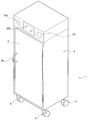
- FIG. 1 is a perspective view when the door 3 of the storage 1 according to the present embodiment is closed.
- FIG. 2 is a perspective view when the door 3 of the storage 1 according to the present embodiment is opened.
- FIG. 3 is a diagram illustrating a rack in the storage 1 and items in the rack according to the present embodiment.
- the storage 1 is configured to accommodate a plurality of items in a substantially rectangular parallelepiped casing 2.
- the caster 4 is attached to the bottom of the housing 2 so as to be movable as a preferred form, but the caster 4 is not necessarily essential.
- the storage 1 of the present embodiment is provided with a door 3 connected to the housing 2.
- a door handle 3 a is attached to the door 3.
- FIG. 1 shows a case where the door 3 is in a closed state in which access from the outside is blocked for a plurality of items stored in the storage 1.
- FIG. 2 shows a case where the door 3 is in an open state in which a plurality of items can be accessed from the outside.
- the door 3 is locked when there is no access from the user, and is unlocked when there is an access from an authenticated user.
- a display panel 22a, a speaker 24a, and an access antenna installation unit 10 are provided above the door 3.
- the access antenna installation unit 10 is a front portion of the housing 2 corresponding to a position where an access antenna AA (not shown) is installed inside the housing 2.
- the position where the access antenna installation unit 10 is provided is an example of a predetermined area on the housing 2.
- the positions of the display panel 22a and the speaker 24a are set so as to be approximately the same height as the position of the user's head when the user stands facing the door 3, thereby allowing the user's visibility to the display panel 22a.
- the sound from the speaker 24a is devised so as to be easy to hear.
- a user card is placed close to the access antenna installation unit 10 (that is, the user card is connected to the access antenna). It is necessary to receive authentication (over the installation unit 10). At this time, since the position of the access antenna installation unit 10 is set to be approximately the same height as the position of the user's head when the user stands facing the door 3, the operability of the user card Is good. Further, in the storage 1 of the present embodiment, the display panel 22a and the position where the access antenna installation unit 10 is provided are arranged at close positions. Therefore, when the card or item is held over the position where the access antenna installation unit 10 is provided, the movement of the line of sight when confirming the processing result displayed on the display panel 22a is small, and the operability is good. .
- rack group R a plurality of stages (seven stages in the example of FIG. 2) of racks R1 to R7 (collectively referred to as “rack group R”) are stacked inside the housing 2 of the storage 1. It is provided in the state that was done.
- Each rack is partitioned by partition plates provided at the top and bottom.
- the rack R1 is provided between the partition plate P0 and the partition plate P1
- the rack R2 is provided between the partition plate P1 and the partition plate P2.
- Each partition plate has a built-in rack antenna. That is, rack antennas RA0 to RA7 are built in partition plates P0 to P7, respectively.
- the rack itself is preferably not made of metal but made of plastic, for example, so as not to affect the reception performance of the rack antennas RA0 to RA7.
- the surface member constituting the external appearance of the housing 2 is preferably a metal member having an electromagnetic shielding function so that electromagnetic waves irradiated from the outside do not affect the receiving performance of the rack antenna. For example, it is possible to prevent the rack antenna in the storage 1 from erroneously detecting an RF tag unrelated to the storage 1 that can approach or contact the housing 2 from the outside of the storage 1.
- FIG. 3 shows an example in which items IM1 to IM6 are accommodated in the rack R1.
- Each item is attached with a label L containing an RF tag (hereinafter referred to as “item tag”) in which data for identifying the item is recorded.
- the item tag is an example of a first tag.
- the item code (Item code), item name (Item Description), expiration date (Expiry date), and lot number (Lot No.) of the item to be pasted are printed. ing. At least one of the item code, the item name, the expiration date, and the lot number is an example of item information.
- each label L can be attached to the item by the adhesive layer.
- the label L can be produced using a printer that writes data to an item tag simultaneously with printing on the front surface. Note that it is not essential to print information on the item code, item name, expiration date, and lot number on the label L, and the information may not be printed on the label L at all.
- the item tag built in each label L includes data consisting of fields of item code, item name, expiration date, and lot number printed on the front surface of each label L (hereinafter referred to as “item data”). Is recorded).
- each partition plate has a built-in rack antenna that transmits radio waves to the item tag.
- the rack antennas RA0 and RA1 built in the partition plates P0 and P1 respectively transmit radio waves to the item tags of all items accommodated in the rack R1, and from the item tags The radio wave (reflected wave) is received.
- the radio wave from the item tag includes item data recorded in the item tag.
- the item tag in the rack R1 can take various positions depending on the position of the item in the rack R1 and the attachment position of the label L, communication with the item tag of the item in the rack R1 is possible.
- Is configured to be performed by two rack antennas RA0 and RA1 respectively incorporated in two partition plates P0 and P1 provided above and below the rack R1.
- transmission / reception of radio waves to / from the item tag of the item in the rack R2 is performed by the rack antennas RA1 and RA2, respectively
- transmission / reception of radio waves to / from the item tag of the item in the rack R3 is performed by the rack. This is performed by the antennas RA2 and RA3.
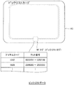
- FIG. 4 is a diagram for explaining the user card UC used in the item storage system of the present embodiment.
- FIG. 5 is a diagram for explaining the pick list card PC used in the item storage system of this embodiment.
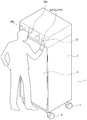
- FIG. 6 is a diagram illustrating a method in which the user uses the user card UC or the picklist card PC in the item storage system according to the present embodiment.
- the user card UC is a card for authenticating a user who accesses the storage 1.
- An RF tag (referred to as “user tag”) is embedded in the user card UC.
- the user tag is an example of a second tag.
- data on a user ID, name, affiliation, and post (hereinafter referred to as “user data”) is recorded.
- the user ID is data used for authentication of a user who uses the user card UC.
- the name, affiliation, and post data are optional information and are not essential information for user authentication. As shown in FIG.
- the user card UC when the user uses the user card UC, the user card UC is made to recognize the user card UC by holding the user card UC over the access antenna installation unit 10 of the storage 1 (in proximity). Note that it is not essential to print information such as the user ID, name, affiliation, and post on the user card UC, and the information may not be printed on the user card UC at all.
- a pick list card is a card used when an item (referred to as a “pick item”) that is desired to be taken out from the storage 1 is taken out from the storage 1.
- an RF tag (referred to as “pick list tag”) is embedded in the pick list card PC.
- Data on item codes and lot numbers (hereinafter referred to as “pick list data”) is recorded in the pick list tag.
- the item code is information for specifying an item.
- the lot number is data assigned to each lot (production unit) when the item is manufactured. That is, the same item with the same lot number is manufactured in the same lot.
- the pick item is specified by the condition indicated by the pick list data.
- FIG. 6 when a user uses a pick list card PC, the pick list card PC is recognized by the storage 1 by holding the pick list card PC over the access antenna installation unit 10 of the storage 1.
- Full Scan is a process of reading item data recorded in item tags attached to all items stored in the storage 1.
- the condition for executing the full scan in the item storage system of the present embodiment is that the storage 1 is activated or that the authenticated user changes the door 3 from the open state to the closed state.
- it may be a condition that a predetermined time has elapsed since the previous full scan was executed or that a preset time has been recognized. In that case, a full scan can be forcibly executed periodically.
- the number of items stored in the storage 1 is large, it may take a long time, for example, about 20 seconds to execute a full scan.
- the user When the authenticated user changes the door 3 from the open state to the closed state, the user takes out the item from the storage 1 and / or receives the item from the storage 1, that is, the user's 1 The transaction for the first access is considered completed.
- the storage 1 can always grasp the latest information of the items stored in the storage 1.
- FIG. 7 is a diagram illustrating a method for a user to scan an item in the item storage system according to the present embodiment.
- the item storage system of the present embodiment when the user holds one item over the access antenna installation unit 10 of the storage 1, the item data recorded in the item tag of the item in a short time is displayed on the display panel 22a. It has a function to be displayed. That is, as shown in FIG. 7, the item is attached to the item IM by causing the storage 1 to recognize the item IM when the user holds (closes) the item IM to the access antenna installation unit 10 of the storage 1.
- the item data recorded in the tag and the determination result as to whether or not the item IM is an appropriate item can be displayed on the display panel 22a.
- this function is referred to as “pick scan”.
- the pick scan can be executed when the door 3 is in the open state, and the operability is good when the user wants to quickly check the data related to the item he / she owns. Note that it may be set so that the pick scan can be executed even when the door 3 is in the closed state.
- FIG. 8 is a block diagram illustrating an internal configuration of the storage according to the present embodiment.
- the storage 1 of the embodiment includes a control unit 20, a reader unit 21, a display unit 22, a storage unit 23, an audio output unit 24, a USB interface 25, a LAN interface 26, a sensor 27, and a door lock unit. 28, an access antenna AA, and a rack antenna group RA.
- the control unit 20 includes a microprocessor, a ROM (Read Only Memory), and a RAM (Random Access Memory) as main elements.
- the ROM stores an OS (Operating System) and application programs, and the microprocessor implements various functions of the storage 1 described later by executing programs read from the ROM when the storage 1 is started. To do.
- the application program recorded in the ROM includes an item management application program (hereinafter simply referred to as “item management application”) for managing items in the storage 1.
- the control unit 20 includes a real time clock IC and constantly measures the current time.
- the control unit 20 is an example of a first control unit and a second control unit.
- the reader unit 21 is configured to exchange data with the control unit 20.
- the reader unit 21 is an example of a first reader and a second reader.
- the reader unit 21 is connected to the access antenna AA and sends a signal to the access antenna AA so that radio waves are radiated from the access antenna AA.
- the reader unit 21 receives data from the access antenna AA, the reader unit 21 transmits the data (that is, the read data) to the control unit 20.
- Data transmitted from the access antenna AA to the control unit 20 is user data, pick list data, or item data.
- the reader unit 21 is connected to each of the rack antennas RA1 to RA7 of the rack antenna group RA, and sends a signal to each rack antenna so that a radio wave is radiated from each rack antenna.
- the reader unit 21 receives data from each of the rack antennas RA1 to RA7, the reader unit 21 transmits the data (that is, the read data) to the control unit 20.
- the data transmitted from each of the rack antennas RA1 to RA7 is item data recorded on an item tag attached to the item IM accommodated in each of the racks R1 to R7.
- the control unit 20 may control the reader unit 21 so that the rack antennas RA1 to RA7 operate when a predetermined condition is satisfied.
- the predetermined condition is, for example, that the storage 1 is activated or that the state of the door 3 is switched from the open state to the closed state.
- the reader unit 21 receives data indicating the open / closed state of the door 3 from the sensor 27, and transmits the data to the control unit 20.
- the reader unit 21 transmits a signal instructing locking (locking) or unlocking (unlocking) the door 3 to the door lock unit 28 based on a control signal from the control unit 20.
- the display unit 22 includes a display drive circuit (not shown) and a display panel 22a, and displays an image on the display panel 22a based on an image signal transmitted from the control unit 20.
- the display panel 22a is, for example, an LCD (Liquid Crystal Display) panel.
- the image displayed on the display panel 22a includes processing results based on data read by the reader unit 21 and various messages such as error messages.
- the display panel 22a is a touch panel that accepts a touch input by a user.
- the storage unit 23 is a non-volatile memory such as a flash memory, for example, and stores a registered user database 231, an inventory database 232, and a transaction log database 233.
- the storage unit 23 is appropriately accessed from the control unit 20, thereby updating each database.
- Each configuration of the registered user database 231, the inventory database 232, and the transaction log database 233 will be described later.
- the audio output unit 24 includes a signal processing circuit (not shown) and a speaker 24a, performs predetermined signal processing on the audio signal transmitted from the control unit 20, and then amplifies and outputs it as an audio message from the speaker 24a. To do.
- the USB interface 25 is connected to an external device compatible with a wireless LAN compliant with IEEE802.11 such as WiFi (registered trademark), and is provided to connect to the Internet or the like.
- the storage 1 of the present embodiment is configured to send an e-mail to a supervisor when a predetermined condition is satisfied via WiFi (registered trademark).
- the LAN interface 26 is provided for connecting to an external device through a wired LAN.
- the sensor 27 is a sensor that detects the open / closed state of the door 3.
- the sensor 27 can be composed of, for example, a transmissive or reflective optical sensor. The detection result by the sensor 27 is sequentially transmitted from the reader unit 21 to the control unit 20.
- the door lock unit 28 includes an electric lock that locks or unlocks the door 3 in accordance with a command from the control unit 20 via the reader unit 21.
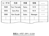
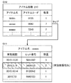
- FIG. 9 is a diagram illustrating a data configuration of the registered user database 231.
- FIG. 10 is a diagram illustrating a data configuration of the inventory database 232.
- FIG. 11 is a diagram illustrating a data configuration of the transaction log database 233.
- the registered user database 231 is a database in which registered users who are permitted to access the storage 1 (hereinafter referred to as “registered users”) are recorded.
- the registered user database 231 is a database that includes data of fields such as user ID, name, affiliation, and title for one record.
- the field provided in the registered user database 231 is the same as or a part of the user data field (see FIG. 4) recorded in the user tag of the user card UC.
- the registered user database 231 is used for authenticating a user who intends to access the inside of the storage 1.
- access permission / denial is determined based on whether or not the user ID recorded in the user card UC matches any user ID recorded in the registered user database 231 will be described. However, it is not limited to this case.
- Access permission / denial information may be recorded in the user card UC, and access permission / denial may be directly determined based on the information. In that case, it is not essential to provide the registered user database 231.
- the inventory database 232 is a database in which the latest item data (that is, item data stored last) of all items stored in the storage 1 is recorded. That is, the item data recorded in the inventory database 232 is the result of the most recent full scan.
- the inventory database 232 is a database that includes data of each field of item code, item name, lot number, and expiration date as one record.
- the field provided in the inventory database 232 is the same as or a part of the field of item data (see FIG. 3) recorded in the item tag attached to each item.
- the inventory database 232 is used to identify changes in items stored in the vault 1 before and after one transaction of the user.
- the transaction log database 233 is a database in which the results of each transaction by the user are recorded in order of date and time.
- the database includes data of each field of transaction ID, user ID, item code, lot number, work code, and log date as one record.
- the transaction ID is identification information for identifying a single transaction by the user, that is, an operation during a period until the door 3 is closed again after the door 3 of the storage 1 is changed from the closed state to the open state. is there.
- the user ID is identification information of a user who has accessed the storage 1 in the transaction corresponding to the transaction ID.
- the item code and the lot number are data of items corresponding to the work code (receipt: 0, delivery: 1).
- the log date and time is the date and time when the transaction corresponding to the transaction ID is completed (for example, the date and time when the door 3 is closed).
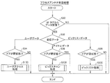
- FIG. 12 is a flowchart showing the activation process of the item storage system according to this embodiment.
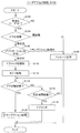
- FIG. 13 is a flowchart showing access antenna reception processing of the item storage system according to the present embodiment.
- FIG. 14 is a flowchart showing user access processing of the item storage system according to the present embodiment.
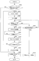
- FIG. 15 is a flowchart showing transaction processing of the item storage system according to the present embodiment.
- FIG. 17 is a flowchart showing pick list processing of the item storage system according to the present embodiment.
- 18 to 20 are diagrams each showing a display example of the storage 1 according to the present embodiment.
- FIG. 18 is a diagram that displays the execution result of the full scan.
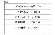
- FIG. 19 is a diagram for displaying the execution result of the pick scan.
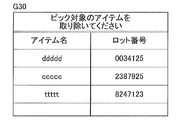
- FIG. 20 is a diagram for displaying an execution result when a pick list card is scanned.
- a message indicating that it cannot be recognized (for example, a message “There is an item that cannot be recognized (item name: aaaaaa). Please remove.”) Is output from the display panel 22a and / or the speaker 24a. “When item data cannot be recognized” is, for example, a case where a lot number is not included or a lot number cannot be recognized as appropriate data.
- the control unit 20 performs a full scan (S12). That is, the control part 20 reads the data currently recorded on the item tag of all the items accommodated in the storage 1 and records it in the inventory database 232 (S14). The control unit 20 determines whether or not an inappropriate item is accommodated in the storage 1 based on the read data (S16). An inappropriate item is, for example, an item whose expiration date has expired. In this case, the determination in S16 is performed based on whether there is a record in which the value of the expiration date field recorded in the inventory database 232 is earlier than the current time. If there is no inappropriate item in the vault 1 (S16: NO), the activation process ends.
- a voice warning message is generated every predetermined time.
- the control unit 20 starts a timer (S18) and controls the audio output unit 24 so that a warning message is output from the speaker 24a (S20).
- S22: NO a predetermined time after the timer is started
- S24: YES the start-up process ends. The process proceeds to an access antenna reception process to be described later.
- the control unit 20 When the predetermined time has elapsed without the user holding the user card UC over the access antenna installation unit 10 after the timer is started (S22: YES), the control unit 20 resets the timer and starts it again to give a warning message.
- the audio output unit 24 is controlled so that the audio output is performed. Therefore, as long as the user card UC is not held over the access antenna installation unit 10, a warning message is output every predetermined time.
- the access antenna reception process is a process when the user holds a card or item over the access antenna installation unit 10 of the storage 1 after the item storage system activation process. Note that the access antenna reception process may be executed by interrupting other processes.
- the control unit 20 does nothing when the door is closed (S36: YES).
- S36: YES When data from the RF tag is received by the access antenna AA (S30: YES) and the received data is picklist data (S32: picklist data), the control unit 20 indicates that the door is closed. (S38: YES), pick list processing is executed (S300). The specific contents of the pick list process are shown in the flowchart of FIG.
- the control unit 20 does nothing when the door is open (S38: NO).
- the control unit 20 performs an authentication process for determining whether or not the user ID included in the user data is valid (S102). In this authentication process, it is determined whether or not the user ID included in the received user data matches the user ID recorded in any record of the registered user database 231, and this is effective when there is a matching user ID. It is determined that it is a user ID.
- the control unit 20 determines the open / closed state of the door 3 based on the sensor output transmitted from the sensor 27 through the reader unit 21 (S104).
- S104 open state
- a message such as “Please wait for a while” is output through the display panel 22a and / or the speaker 24a (S108), and the process ends.
- the control unit 20 determines whether the state of the item management application is a transaction process or an access is being accepted (S106). “Transaction processing is in progress” means, for example, that a full scan is being executed on the condition that the user who has just accessed the door has closed the door. If the next user's access is permitted during a full scan for the previous user's transaction, the previous user's transaction cannot be accurately recorded in the transaction log database 233. Therefore, while a full scan is being executed for the previous user's transaction, access to the next user is prohibited. If a transaction is being processed (S106: Transaction is being processed), a message such as “Please wait for a while” is output through the display panel 22a and / or the speaker 24a (S108), and the process ends. If it is determined in S106 that the access is being accepted (S106: being accepted), the access is permitted and the process proceeds to S110.
- the control unit 20 When access is permitted, the control unit 20 first controls the door lock unit 28 via the reader unit 21 to release the door lock of the door 3 (S110).
- the door 3 is configured to be locked when the door 3 is not opened before a predetermined time elapses after the door 3 is unlocked.
- the control unit 20 first starts a timer (S112), and when it is determined that the door 3 is not open (S114: NO), it waits until a predetermined time elapses (S116: NO).
- S114: YES the control unit 20 executes the transaction process and ends (S120). The transaction process will be described later.
- the control unit 20 locks the door via the reader unit 21 so that the door 3 is locked.
- the unit 28 is controlled (S118), and the process ends.
- FIG. 15 shows the detailed flow of the transaction process (S120) of FIG.
- a transaction ID is assigned with a period from when the door 3 is opened by the user having a valid user ID to when the door 3 is closed again as a period in which one transaction is performed.
- the result of the user entering the item into the storage 1 and / or issuing the item from the storage 1 within this period is recorded in the transaction log database 233 in association with the transaction ID.
- the control unit 20 issues a new transaction ID (S122).
- the control unit 20 waits until the user's work is completed, that is, until the door 3 is closed again (S124: NO), and determines that the door 3 is closed (S124: YES). Then, it is determined that the transaction by the user has ended, and the processing from S126 is performed.
- the control unit 20 controls the door lock unit 28 via the reader unit 21 so that the door 3 is locked (S126), and then performs a full scan. That is, the control unit 20 performs a process of reading data recorded in item tags attached to all items stored in the storage 1. Furthermore, the control unit 20 controls the display unit 22 to display the result of the full scan (S128).
- the image G10 in FIG. 18 shows an example of a full scan result displayed on the display panel 22a.
- a list for each item (item name, item code, quantity) is displayed together with the total number of items in the vault 1.
- more detailed information of the item may be displayed.
- FIG. 18 by tapping the line corresponding to the item name: aaaaaa in the list of the image G10, as the detailed information of the item name: aaaaaa, the expiration date, lot number, and quantity information
- An image G11 including is displayed.
- the control unit 20 determines whether or not a predetermined warning occurrence condition is satisfied (S130).
- the warning generation conditions are not limited to the following conditions, but examples include the following conditions.
- the control unit 20 compares the execution result of S128 with the inventory database 232 (that is, the latest data based on the transaction being executed). . In order to determine whether or not the condition 3 is satisfied, the control unit 20 compares the execution result of S128 with the current time. The determination as to whether or not the condition 4 is satisfied may be made when the storage 1 stores picklist data in the RAM. In other words, this is performed when the user who is executing the transaction or another user causes the storage 1 to read the pick list data included in the pick list card PC, and the storage 1 holds the pick list data. It may be broken. In this case, the control unit 20 compares the pick list data with the execution result of S128 and determines whether or not the condition 4 is satisfied.
- the control unit 20 updates the inventory database 232 (inventory DB) based on the execution result of the full scan in S128 (S132), and the transaction log
- the database 233 (transaction log DB) is updated (S134).
- the control unit 20 first receives the warehousing and / or item for each item based on the difference between the data recorded in the inventory database 232 immediately before S132 and the execution result of the full scan in S128. Or specify the contents of the issue.
- the control unit 20 adds one or more records to the transaction log database 233 by associating the identified contents with the user ID included in the received user data (see S30 in FIG. 13).
- the control unit 20 outputs a message indicating that the transaction has ended normally (S150), and ends the transaction processing.
- the control unit 20 When any one of the warning generation conditions is satisfied (S130: YES), the control unit 20 outputs the warning message corresponding to the warning generation condition to the display panel 22a and / or the speaker 24a.
- the audio output unit 24 is controlled (S136).
- the control unit 20 starts a timer (S138), and determines whether or not user data is received before the predetermined time elapses (that is, whether or not the user card is held over the access antenna installation unit 10) (S142). ).
- the control unit 20 updates the inventory database 232 (inventory DB) (S144) and updates the transaction log database 233 (transaction log DB). Update (S146).
- the control unit 20 transmits an e-mail notifying that an error has occurred in the vault 1 to the supervisor's e-mail address registered in advance (S148), and ends the transaction process.
- the control unit 20 displays the user data in FIG. Re-execute the access process.
- S102 it is preferable to determine that only the user ID identical to the user ID of the user performing the transaction process is valid. In other words, only the user who generated the warning starts the transaction again within a predetermined time, and receives the item from the storage 1 and / or issues the item from the storage 1 so that the warning does not occur.
- control unit 20 shifts to S100 only when valid user data is received, and receives user data without shifting to S100 when user data other than valid user data is received. You may perform the process similar to not having.
- “effective user data” is user data including data indicating a specific employee, such as an item manufacturer or an item wholesaler. By allowing the warning to be canceled only by a user having a special authority, it is possible to reliably carry out appropriate maintenance for the items stored in the storage 1.
- the received item data is displayed and the determination result (OK) is displayed (S204).
- An image G20 in FIG. 19 shows an example of the pick scan result. In this example, an item name, an item code, an expiration date, and a lot number are displayed as received item data, and “Pick scan result: OK” is displayed as a determination result.
- the received item data is displayed and the determination result (warning) is displayed (S206). The user holds an item to be stored in the storage 1 during the transaction or an item to be output from the storage 1 over the access antenna installation unit 10 to determine whether the item is an appropriate item (that is, Whether the item does not satisfy the warning condition) can be recognized immediately.
- the control unit 20 controls the display unit 22 so that a predetermined message is displayed on the display panel 22a (S306), and starts a timer (S308).
- a predetermined message is displayed on the display panel 22a in S306
- a timer S308
- FIG. 20 An example of an image including the predetermined message displayed on the display panel 22a in S306 is shown in FIG. In the image G30 in FIG. 20, a list of items to be delivered from the storage 1 (item name and lot number of each item) is displayed, and a message prompting the user to deliver the item is displayed.
- the door lock is released (S312).
- Effective user data is user data corresponding to a user who is authorized to issue (or collect) items that satisfy a specific item or a specific condition from the vault 1 as items to be issued. is there. That is, here, it is assumed that a user who has been previously given authority to issue items is registered in the registered user database 231 among registered users. In that case, the control unit 20 searches the registered user database 231 using the user ID included in the received user data as a key, and determines whether the user data is valid.
- the door lock is released (S312), and the user can perform the leaving work with the door 3 opened.
- the control unit 20 determines that the leaving operation is finished (S314: YES), performs a full scan, and displays the result on the display panel 22a. Is displayed (S316). That is, the control unit 20 performs a process of reading data recorded in item tags attached to all items stored in the storage 1. Next, the control unit 20 determines whether or not all pick items have been delivered (collected) from the storage 1 (S318).
- the determination in S318 is performed as follows. That is, the control unit 20 extracts item data satisfying the item condition indicated by the pick list data received in S30 from the item data stored in the inventory database 232 (that is, the execution result of the previous full scan). To do. That is, the control unit 20 extracts a pick item from items in the storage 1 that has been subjected to the previous full scan. Next, the control unit 20 determines whether or not the extracted pick item is included in the items in the storage 1 that has been subjected to the full scan in S316. And when the pick item is not included, the control unit 20 determines that all the pick items have been issued, and if at least one pick item is included, all the pick items have not been issued. to decide.
- the inventory database 232 is updated based on the execution result of the full scan in S316 (S230), and a normal end message is displayed ( S304), the process ends. If it is determined that not all pick items have been issued from the storage 1 (S318: NO), the process returns to S306 and a warning message is output. The processes of S306 to S318 are repeated until all items corresponding to the conditions indicated by the pick list data are delivered from the storage 1. However, if valid user data is not received within a predetermined time after the warning message is output (S322: YES), the warning message is canceled (S324), and the process ends and returns to normal operation. In S324, the warning message is canceled when the user card UC is not held over the access antenna installation unit 10 within a predetermined time because the other user wants to take out the item in the vault 1 in an emergency. .
- first mode the control with the warning condition as the condition M1
- second mode the control with the warning condition as the condition M2
- the expiration date of the item may pass while being stored in the storage 1. Therefore, in the storage 1 of the present embodiment, it is preferable to manage the expiration date of the items accommodated in the storage 1 as described below.
- the control unit 20 sequentially compares the expiration date value of each item in the inventory database 232 with the current time, and determines that the expiration date value of any item has not reached the current time.
- the warning generation condition is set as the condition M1 (S410).
- the warning occurrence condition is the condition M1
- the condition M1 that is, in the first mode, only items with the shortest period until the expiration date can be removed from the items with the same item code.
- a warning message is output. A warning message is output even when an expired item is issued.
- the warning occurrence condition is the condition M1, that is, in the first mode, only items with the shortest period until the expiration date can be removed from the items with the same item code.
- a warning message is output. A warning message is output even when an expired item is issued.
- the control unit 20 When the user holds the user card UC over the access antenna installation unit 10 within a predetermined time after the confirmation message of S406 is output, that is, when the storage 1 receives user data (S408: YES), the control unit 20 recognizes that the user issues an expired item, and sets the warning generation condition in S130 (see FIG. 15) as a condition M2 (S412).
- the warning occurrence condition is the condition M2, that is, in the second mode, only the expired item can be removed, and a warning message is output when an item other than the expired item is issued.
- the A warning message is output even when an item with the shortest period from the item with the same item code is issued.
- the warning is issued when an item whose expiration date has not expired is issued because the intention of the user who issues the item whose expiration date has expired has already been confirmed in S408. If the vault 1 does not receive user data within a predetermined time after the confirmation message in S406 is output (S408: NO), the warning generation condition in S130 (see FIG. 15) is set as the condition M1 (S410). ).
- step S130 it may be determined that the condition M1 is no longer satisfied (S130: NO).
- condition M1 in S130 is satisfied is determined based on the item delivery result within the predetermined time set in S140. If the item determined to satisfy the condition M1 is not returned to the repository 1 within the predetermined time (S140: YES), the control unit 20 controls the USB interface 25 to control the supervisor's e-mail address. An e-mail is transmitted to (S148).
- the warning generation condition is set to the condition M2, and the execution of the user access process of FIG. 14 is started.
- S130: YES When it is determined in the transaction process (FIG. 15) that an item other than the item whose expiration date has passed has been issued (that is, the condition M2 is satisfied) (S130: YES), a warning message is output (S136). .
- the user access process is executed again within a predetermined time (S142: YES ⁇ S100), and in the transaction process (FIG. 15), the item determined to have been issued recently is received again (that is, the storage 1).
- step S130 it may be determined that the condition M2 is no longer satisfied (S130: NO).
- condition M2 in S130 is satisfied is determined based on the item delivery result within the predetermined time set in S140. If the item determined to satisfy the condition M2 is not returned to the repository 1 within the predetermined time (S140: YES), the control unit 20 controls the USB interface 25 to control the supervisor's e-mail address. An e-mail is transmitted to (S148).
- condition M ⁇ b> 1 is a warning generation condition, and therefore the user has the same item code. Control is performed so that the item having the shortest period until the expiration date is issued first. Therefore, in a normal case, the items in the storage 1 are managed so that they are efficiently delivered and used. That is, the possibility that the item will expire can be reduced.
- control with the warning occurrence condition as condition M1 (first mode) or the warning occurrence condition is determined by the operation of whether or not the user card UC is held over.
- the user can select one of the controls (second mode) set to M2. Therefore, according to the user's purpose, the user can determine whether to give priority to removing an item whose expiration date has expired or give priority to issuing an item to be used. Therefore, misuse prevention with respect to a user's storage 1 can be aimed at.
- the control unit 20 selects either the first mode or the second mode based on whether or not the user performs an operation of holding the user card UC over the access antenna installation unit 10 in S408.
- the present invention is not limited to this case. Since the user ID has already been recognized in S404, the user may select either the first mode or the second mode by a touch operation on the display panel 22a in S408. Note that a system with high operability can be realized by performing an operation with the user card UC in both S404 and S408.
- the control unit 20 displays the item. You may control the display part 22 and / or the audio
- the current time is three days before the expiration date of any item in the vault 1, the fact that the expiration date of the item is near is displayed and / or notified by voice.
- the user can perform an appropriate treatment (for example, preferential use of the item) before the expiration date elapses for an item whose expiration date is close.
- the time referred to in the flowchart is not limited to the item expiration date, and may be a reference time based on the item expiration date.
- the reference time of the item can be set to a desired time based on the expiration date of the item.
- the reference time of an item may be a time two days before the expiration date of the item with a margin in advance. It is not necessary to set the reference time uniformly for the items in the storage 1, and the items may be set appropriately for each item. By setting the item reference time, the expiration date can be managed flexibly for each item.
- the execution time of the full scan may take 20 seconds or more depending on the total number of items stored in the storage 1. Therefore, it may be inconvenient for the user because the user may close the door 3 of the storage 1 and confirm that the transaction by the user has been completed normally (that is, waiting time). Therefore, the user can use the pick scan to reduce the waiting time or to eliminate the waiting time. For example, when a user is executing a transaction and the door 3 is in an open state, when the item is to be released from the storage 1, the item is held over the access antenna installation unit 10 (that is, a pick scan is performed) You can check if you are going to issue a new item.
- the identification of the item that has been issued is determined by the execution result of the full scan, if it is known that an appropriate item is to be issued by the pick scan, the user closes the door 3 and ends the transaction. It is possible to leave the storage 1 immediately without waiting for the result of the full scan. Therefore, there is a merit especially in the use of taking out a small amount of items.
- (5-2) Pick List Card Pick items are scheduled to be issued from a plurality of storage boxes 1 arranged at various locations. For example, when an item is a medicine, it is necessary to issue an item satisfying a specific condition from the storage 1 installed in various hospitals. In such a situation, when the storage 1 is operating without being connected to the network, all items stored in each of the plurality of storages 1 installed in each hospital are, for example, on paper It is complicated to take out only the pick item visually from the storage 1 by comparing with the listed list. There is also a problem that the operator cannot immediately know whether all items to be removed (that is, items to be delivered) have been removed from the storage 1. On the other hand, in the pick list card of the present embodiment, the pick item can be specified in advance from the storage 1 before work.
- the pick item when the pick item is not included in the storage 1, it is not necessary to perform useless search work. Even if the pick item is included in the storage 1, since the item that is the target of the search is known in advance, the user can take out the pick item from the storage 1 relatively easily. In particular, when the storage 1 is installed in various places, the user can go around the place where the storage 1 is installed with only the pick list card, and take out all the pick items. That is, a desired item in the storage can be reliably taken out.
- items to be delivered from the storage 1 in the pick list process are not particularly limited. That is, the conditions for items to be delivered can be set as appropriate. For example, if a large amount of a specific type of item is required and collected from each vault, the RF tag built in the card contains an item code that specifies the type of item to be collected and information on the item condition. Write in advance. When the item to be delivered is an item to be recalled, information on conditions (for example, item code and lot number) that can identify the item to be recalled is included as pick list data.
- conditions for example, item code and lot number
- the information related to the item condition may be any information as long as it is a condition that can be used as a search condition for the item data of the item in the storage 1 so that the user can retrieve the item from the storage 1.
- item data is data including at least one of the corresponding item name, item code, expiration date, and lot number
- the item condition is item name, item code, expiration date, lot number Conditions including at least one of them may be used.
- the warning occurrence condition “the item having an expired expiration date exists in the storage 1” is described, but “the time from the current time to the expiration date is shorter than the predetermined time. It may be. At this time, the length of the predetermined time can be appropriately determined according to the item to be stored.
- the case where the full scan is executed when the door 3 is changed from the opened state to the closed state is not limited to this case.
- a full scan may be periodically executed.
Landscapes
- Engineering & Computer Science (AREA)
- Physics & Mathematics (AREA)
- General Physics & Mathematics (AREA)
- Business, Economics & Management (AREA)
- Theoretical Computer Science (AREA)
- Health & Medical Sciences (AREA)
- Toxicology (AREA)
- Economics (AREA)
- Mechanical Engineering (AREA)
- Computer Networks & Wireless Communication (AREA)
- Electromagnetism (AREA)
- General Health & Medical Sciences (AREA)
- Artificial Intelligence (AREA)
- Computer Vision & Pattern Recognition (AREA)
- Accounting & Taxation (AREA)
- Operations Research (AREA)
- Development Economics (AREA)
- General Business, Economics & Management (AREA)
- Entrepreneurship & Innovation (AREA)
- Human Resources & Organizations (AREA)
- Marketing (AREA)
- Finance (AREA)
- Quality & Reliability (AREA)
- Strategic Management (AREA)
- Tourism & Hospitality (AREA)
- Computer Security & Cryptography (AREA)
- General Engineering & Computer Science (AREA)
- Warehouses Or Storage Devices (AREA)
Abstract
Description
前記複数のアイテムを収容する筐体と、
前記筐体と連結して設けられ、前記筐体内の前記複数のアイテムに対する外部からのアクセスが可能となる開状態、または、前記筐体内の前記複数のアイテムに対する外部からのアクセスが遮断される閉状態のいずれかの状態となるドアと、
前記ドアが閉状態である場合に、前記筐体内に収容された全てのアイテムの第1タグに記録されているアイテム情報を読み出す第1リーダと、
前記ドアが開状態である場合に、第1タグが取り付けられたアイテムを前記筐体の外部から前記筐体上の所定の領域に近接させたときに、当該第1タグに記録されているアイテム情報を読み出す第2リーダと、
前記第1リーダまたは前記第2リーダによって読み出されたアイテム情報を表示パネルに表示する表示部と、
アイテム情報を記憶する記憶部と、
前記第1リーダによって読み出されたアイテム情報を前記記憶部に記憶させるとともに、前記第2リーダによって読み出されたアイテム情報が警告発生条件を満たすか否かの判定結果を、当該アイテム情報に基づいて、または、当該アイテム情報と前記記憶部が記憶するアイテム情報とを比較することによって決定する第1制御部と、
を備える。
前記警告発生条件は、前記第2リーダによって読み出されたアイテム情報と、前記記憶部が最後に記憶したアイテム情報とに基づいて、前記所定の領域に近接させたアイテムが、前記筐体内に収容された同一のアイテムコードのアイテムのうち有効期限までの期間が最短ではないアイテムである、若しくは有効期限が切れたアイテムであると判断したことであってもよい。
前記ドアを開錠または施錠するドアロック部と、
前記ドアロック部を制御する第2制御部と、をさらに備え、
前記ドアが閉状態である場合、前記第2リーダは、ユーザを識別するユーザ識別情報が記録された第2タグを、前記筐体の外部から前記筐体の前記所定の領域に近接させたとき、前記第2タグに記録されているユーザ識別情報を読み出し、
前記第2制御部は、前記第2リーダによって読み出されたユーザ識別情報の認証が成功した場合に、前記ドアが開錠されるように前記ドアロック部を制御してもよい。
本発明の実施形態において、本発明の第1制御部および第2制御部は、単一のデバイスによって実現されてもよいし、複数のデバイスによって実現されてもよい。本発明の第1リーダおよび第2リーダは、単一のデバイスによって実現されてもよいし、複数のデバイスによって実現されてもよい。
以下、実施形態に係るアイテム保管システムについて説明する。
実施形態に係るアイテム保管システムでは、アイテムを保管する保管庫と、ラベルが取り付けられて保管対象となるアイテムと、カード(後述するユーザカードUCおよびピックリストカードPC)とが使用される。ラベルとカードにはRFタグが内蔵されており、保管庫1には当該RFタグに電波を放射するアンテナが搭載されている。アンテナとRFタグは、RFID(Radio Frequency Identification)技術によって無線通信を行う。RFIDによる無線通信方式であれば如何なる方式でもよいが、PJM(Phase Jitter Modulation)方式のパッシブ型RFIDであることが、高速かつ大量なデータの認識を可能にする点で好ましい。
先ず、本実施形態に係る保管庫1について図1~3を参照して説明する。
図1は、本実施形態に係る保管庫1のドア3を閉状態としたときの斜視図である。図2は、本実施形態に係る保管庫1のドア3を開状態としたときの斜視図である。図3は、本実施形態に係る保管庫1内のラックとラック内のアイテムを例示する図である。
図1および図2に示すように、保管庫1は、概ね直方体状の筐体2の内部に複数のアイテムを収容するようにして構成されている。図1および図2では、好ましい形態として移動可能となるように筐体2の底部にキャスタ4を取り付けた形態を示しているが、キャスタ4は必ずしも必須ではない。
アクセスアンテナ設置部10は、筐体2内部に図示しないアクセスアンテナAAが設置されている位置に対応した、筐体2の前面の部分である。アクセスアンテナ設置部10が設けられている位置は、筐体2上の所定の領域の一例である。
表示パネル22aおよびスピーカ24aの位置は、ユーザがドア3と対向して立っているときにユーザの頭の位置と同程度の高さとなるように設定され、それによってユーザの表示パネル22aに対する視認性やスピーカ24aからの音声に対する聞き取りやすさが良好となるように工夫されている。
また、本実施形態の保管庫1では、表示パネル22aとアクセスアンテナ設置部10が設けられている位置とが近接した位置に配置されている。そのため、カードやアイテムをアクセスアンテナ設置部10が設けられている位置にかざした場合、表示パネル22aに表示される処理結果の確認時の視線移動が少なくて済み、操作性が良好となっている。
なお、ラックアンテナRA0~RA7による受信性能に影響を及ぼさないように、ラック自体は金属製ではなく、例えばプラスチック製であることが好ましい。
筐体2の外観を構成する表面部材は、外部から照射される電磁波がラックアンテナの受信性能に影響を与えないように、電磁シールド機能を備えた金属製の部材であることが好ましい。例えば、保管庫1の外部から筐体2に近接または接触しうる、保管庫1とは無関連のRFタグを、保管庫1内のラックアンテナが誤検出することを防止することができる。
各ラベルLの裏面には粘着層が形成されており、粘着層によってアイテムにラベルLを取り付けられるように構成されている。ラベルLは、おもて面への印字と同時にアイテムタグへのデータ書き込みを行うプリンタを使用して作製することができる。なお、ラベルLにアイテムコード、アイテム名、有効期限、および、ロット番号の情報を印字することは必須ではなく、情報がラベルLに全く印字されていなくてもよい。
他のラックについても同様である。例えば、ラックR2内のアイテムのアイテムタグとの間の電波の送受信は、それぞれ、ラックアンテナRA1,RA2によって行われ、ラックR3内のアイテムのアイテムタグとの間の電波の送受信は、それぞれ、ラックアンテナRA2,RA3によって行われる。
次に、本実施形態のアイテム保管システムにおいて使用されるカードの構成およびカードの使用方法について、図4~6を参照して説明する。
図4は、本実施形態のアイテム保管システムで使用されるユーザカードUCを説明する図である。図5は、本実施形態のアイテム保管システムで使用されるピックリストカードPCを説明する図である。図6は、本実施形態に係るアイテム保管システムにおいて、ユーザがユーザカードUCまたはピックリストカードPCを使用する方法を説明する図である。
ユーザカードUCとは、保管庫1にアクセスするユーザを認証するためのカードである。
図4に例示するユーザカードUCのおもて面には、ユーザの顔写真、ユーザIDおよび名前についての情報が印字されている。ユーザカードUCにはRFタグ(「ユーザタグ」という。)が埋め込まれている。ユーザタグは、第2タグの一例である。
ユーザタグには、ユーザID、名前、所属、および、役職についてのデータ(以下、「ユーザデータ」という。)が記録されている。ユーザIDは、ユーザカードUCを使用するユーザの認証に使用されるデータである。名前、所属、および、役職についてのデータは任意的な情報であり、ユーザの認証を行うのに必須の情報ではない。
図6に示すように、ユーザがユーザカードUCを使用する場合、ユーザカードUCを保管庫1のアクセスアンテナ設置部10にかざす(近接させる)ことで保管庫1にユーザカードUCを認識させる。
なお、ユーザカードUCにユーザID、名前、所属、および、役職等の情報を印字することは必須ではなく、情報がユーザカードUCに全く印字されていなくてもよい。
ピックリストカードとは、保管庫1から出庫させたいアイテム(「ピックアイテム」という。)を保管庫1から取り出すときに使用するカードである。
図5に示すように、ピックリストカードPCにはRFタグ(「ピックリストタグ」という。)が埋め込まれている。ピックリストタグには、アイテムコードおよびロット番号についてのデータ(以下、「ピックリストデータ」という。)が記録されている。アイテムコードは、アイテムを特定する情報である。ロット番号は、アイテムを製造したときのロット(生産単位)ごとに付されているデータである。すなわち、同一のロット番号が付された同一のアイテムは、同一のロットで製造されたことを意味する。ピックリストデータが示す条件によってピックアイテムが特定される。
図6に示すように、ユーザがピックリストカードPCを使用する場合、ピックリストカードPCを保管庫1のアクセスアンテナ設置部10にかざす(近接させる)ことで保管庫1にピックリストカードPCを認識させる。
次に、実施形態に係るアイテム保管システムに設けられている処理の一つであるフルスキャンについて説明する。
「フルスキャン」とは、保管庫1内に保管されているすべてのアイテムに取り付けられているアイテムタグに記録されたアイテムデータを読み出す処理である。本実施形態のアイテム保管システムにおいてフルスキャンを実行する条件は、保管庫1が起動されたこと、または、認証されたユーザがドア3を開状態から閉状態に変更したことである。また、前回のフルスキャンを実行してから所定の時間が経過したこと、または予め設定された時刻になったことを認識したことを条件としてもよい。その場合、定期的にフルスキャンを強制実行させることもできる。保管庫1内に収容されているアイテムの数が多い場合、フルスキャンを実行するには例えば20秒程度の長い時間が掛かる場合がある。
認証されたユーザがドア3を開状態から閉状態に変更した場合、当該ユーザが保管庫1からのアイテムの出庫、および/または、保管庫1へのアイテムの入庫の作業、つまり、ユーザの1回のアクセスに対するトランザクションが終了したと考えられる。このタイミングでフルスキャンを実行することで、保管庫1に収容されているアイテムの最新情報を保管庫1が常時把握することができる。
次に、図7を参照して、実施形態に係るアイテム保管システムに設けられている処理の一つであるピックスキャンについて説明する。図7は、本実施形態に係るアイテム保管システムにおいてユーザがアイテムをスキャンする方法を説明する図である。
本実施形態のアイテム保管システムは、ユーザが保管庫1のアクセスアンテナ設置部10に対して1つのアイテムをかざすことで、短時間で当該アイテムのアイテムタグに記録されているアイテムデータを表示パネル22aに表示させる機能を備える。すなわち、図7に示すように、ユーザがアイテムIMを保管庫1のアクセスアンテナ設置部10にかざす(近接させる)ことで保管庫1にアイテムIMを認識させ、当該アイテムIMに取り付けられているアイテムタグに記録されたアイテムデータや、当該アイテムIMが適切なアイテムであるか否かの判定結果を表示パネル22aに表示させることができる。以下の説明では、この機能を「ピックスキャン」という。
ピックスキャンは、ドア3の開状態のときに実行可能であり、ユーザが自身の所持しているアイテムに関するデータを素早く確認したい場合の操作性が良い。なお、ドア3が閉状態のときにおいてもピックスキャンが実行可能となるように設定してもよい。
次に、本実施形態の保管庫1の内部構成について、図8を参照して説明する。図8は、本実施形態に係る保管庫の内部構成を示すブロック図である。
図8に示すように、実施形態の保管庫1は、制御部20、リーダユニット21、表示部22、記憶部23、音声出力部24、USBインタフェース25、LANインタフェース26、センサ27、ドアロック部28、アクセスアンテナAA、および、ラックアンテナ群RAを含む。
制御部20は、第1制御部および第2制御部の一例である。
リーダユニット21は、アクセスアンテナAAと接続され、アクセスアンテナAAから電波が放射されるようにアクセスアンテナAAに信号を送る。リーダユニット21は、アクセスアンテナAAからデータを受信した場合に、当該データ(つまり、読み出したデータ)を制御部20へ送信する。アクセスアンテナAAから制御部20へ送信されるデータは、ユーザデータ、ピックリストデータ、または、アイテムデータのいずれかである。
なお、制御部20は、所定の条件を満たしたときにラックアンテナRA1~RA7が動作するようにリーダユニット21を制御してもよい。所定の条件は、例えば、保管庫1が起動されたこと、または、ドア3の状態が開状態から閉状態に切り替わったことである。
本実施形態の例では、表示パネル22aは、ユーザによるタッチ入力を受け付けるタッチパネルである。
LANインタフェース26は、有線LANを通して外部機器に接続するために設けられている。
次に、本実施形態のアイテム保管システムにおいて参照されるデータベースについて、図9~11を参照して説明する。
図9は、登録ユーザデータベース231のデータ構成を例示する図である。図10は、在庫データベース232のデータ構成を例示する図である。図11は、トランザクションログデータベース233のデータ構成を例示する図である。
登録ユーザデータベース231は、保管庫1の内部にアクセスしようとするユーザの認証を行うために使用される。
なお、本実施形態では、ユーザカードUCに記録されているユーザIDが登録ユーザデータベース231に記録されているいずれかのユーザIDと一致するか否かによってアクセス許否を判断する場合について例示的に説明するが、この場合に限られない。ユーザカードUC内にアクセス許否の情報が記録されており、当該情報に基づいてアクセス許否を直接判断するようにしてもよい。その場合、登録ユーザデータベース231を設けることは必須ではない。
図10に示す例では、在庫データベース232は、1件のレコードとして、アイテムコード、アイテム名、ロット番号、および、有効期限の各フィールドのデータを含むデータベースである。在庫データベース232に設けられるフィールドは、各アイテムに取り付けられているアイテムタグに記録されているアイテムデータのフィールド(図3参照)と同一であるか、またはその一部である。
在庫データベース232は、保管庫1内に収容されているアイテムの、ユーザの1回のトランザクションの前後での変化を特定するために使用される。
次に、アイテム保管システムにおいて実行される処理について、図12~19を参照して説明する。図12は、本実施形態に係るアイテム保管システムの起動処理を示すフローチャートである。図13は、本実施形態に係るアイテム保管システムのアクセスアンテナ受信処理を示すフローチャートである。図14は、本実施形態に係るアイテム保管システムのユーザアクセス処理を示すフローチャートである。図15は、本実施形態に係るアイテム保管システムのトランザクション処理を示すフローチャートである。図17は、本実施形態に係るアイテム保管システムのピックリスト処理を示すフローチャートである。
図18~20はそれぞれ、本実施形態に係る保管庫1の表示例を示す図である。図18は、フルスキャンの実行結果を表示する図である。図19は、ピックスキャンの実行結果を表示する図である。図20は、ピックリストカードをスキャンしたときの実行結果を表示する図である。
保管庫1の電源を起動すると、保管庫1の制御部20はOSを立ち上げ、OS上で保管庫1のアイテムの管理を行うためのアイテム管理アプリケーションを読み出して起動し(S10)、実行する。制御部20は、アイテム管理アプリケーションを実行することで、以下で述べる処理を実行する。
なお、保管庫1を起動後に所定時刻にフルスキャンを実行する場合には、図12のフローチャートのS12以降の処理を当該所定時刻に実行する。
アクセスアンテナ受信処理は、アイテム保管システムの起動処理の後、ユーザが保管庫1のアクセスアンテナ設置部10にカードやアイテムをかざした場合の処理である。なお、アクセスアンテナ受信処理は、他の処理を実行中に割り込んで実行してもよい。
アクセスアンテナAAでRFタグからのデータを受信し(S30:YES)、その受信データがアイテムデータである場合(S32:アイテムデータ)には、制御部20は、ドアが開状態であることを条件として(S36:NO)、ピックスキャン処理を実行する(S200)。ピックスキャン処理の具体的な内容は、図16のフローチャートに示される。制御部20は、ドアが閉状態のときには何も実行しない(S36:YES)。
アクセスアンテナAAでRFタグからのデータを受信し(S30:YES)、その受信データがピックリストデータである場合(S32:ピックリストデータ)には、制御部20は、ドアが閉状態であることを条件として(S38:YES)、ピックリスト処理を実行する(S300)。ピックリスト処理の具体的な内容は、図17のフローチャートに示される。制御部20は、ドアが開状態のときには何も実行しない(S38:NO)。
制御部20は、アクセスアンテナAAで受信したデータがユーザデータである場合、ユーザデータに含まれるユーザIDが有効であるか否かを判定する認証処理を行う(S102)。この認証処理では、受信したユーザデータに含まれるユーザIDが登録ユーザデータベース231のいずれかのレコードに記録されたユーザIDと一致するか否か判断し、一致するユーザIDが存在する場合に有効なユーザIDであると判断する。
ユーザIDが有効である場合には(S102:YES)、制御部20は、センサ27からリーダユニット21を通して送信されるセンサ出力に基づいて、ドア3の開閉状態を判定する(S104)。ドア3が開状態である場合には(S104:開状態)、他のユーザが保管庫1へのアイテムの入庫中であるか、または保管庫1からのアイテムの出庫中であると考えられる。そこで、例えば「しばらくお待ちください」等といったメッセージを、表示パネル22aおよび/またはスピーカ24aを通して出力し(S108)、終了する。
S106においてアクセスが受付中であると判断された場合(S106:受付中)、アクセスが許容されてS110へ進む。
本実施形態の例では、ドア3のロックが解除されてから所定時間が経過するまでにドア3を開状態としない場合にはドア3がロックされるように構成されている。具体的には、制御部20は先ずタイマを始動させ(S112)、ドア3が開状態となっていないと判定した場合には(S114:NO)、所定時間が経過するまで待機する(S116:NO)。制御部20は、所定時間が経過するまでにドア3が開状態となったと判定した場合には(S114:YES)、トランザクション処理を実行して終了する(S120)。トランザクション処理については、後述する。タイマが始動してからドア3が開状態とならずに所定時間が経過した場合には(S116:YES)、制御部20は、ドア3がロックされるようにリーダユニット21を介してドアロック部28を制御して(S118)、終了する。
図15に示すフローチャートは、図14のトランザクション処理(S120)の詳細な流れを示している。
トランザクション処理では、有効なユーザIDのユーザによってドア3が開状態となってから再び閉状態となるまでの期間を1回のトランザクションが行われた期間として、トランザクションIDが割り当てられる。この期間内にユーザが保管庫1内にアイテムを入庫し、および/または、保管庫1からアイテムを出庫した結果が、トランザクションIDに関連付けてトランザクションログデータベース233に記録される。
制御部20は、ドア3がロックされるようにリーダユニット21を介してドアロック部28を制御し(S126)、次いでフルスキャンを実行する。すなわち、制御部20は、保管庫1内に保管されているすべてのアイテムに取り付けられているアイテムタグに記録されたデータを読み出す処理を行う。さらに制御部20は、フルスキャンの結果を表示するように表示部22を制御する(S128)。
(条件1)同一のアイテムコードのアイテムのうち有効期限までの期間が最短ではないものが出庫されたこと(つまり、ユーザが、有効期限が近いものよりも有効期限が遠いものを出庫したこと)
(条件2)有効期限が切れたアイテムが出庫されたこと
(条件3)保管庫1内に有効期限が切れたアイテムが存在すること
(条件4)保管庫1内にピック対象であるアイテムが存在すること
条件3を満足するか否かを判断するために、制御部20は、S128の実行結果と、現在時刻とを比較する。
条件4を満足するか否かについての判断は、保管庫1がRAMにピックリストデータを記憶している場合に行われてもよい。つまり、トランザクションを実行中のユーザや、別のユーザがピックリストカードPCに含まれるピックリストデータを保管庫1に読み取らせたことで、保管庫1がピックリストデータを保持している場合に行われてもよい。その場合、制御部20は、ピックリストデータとS128の実行結果とを比較して、条件4を満足するか否かを判断する。
なお、S140において制御部20は、有効なユーザデータを受信した場合に限りS100へ移行させ、有効なユーザデータ以外のユーザデータを受信した場合にはS100へ移行させずにユーザデータを受信していないのと同様の処理を行ってもよい。ここで、「有効なユーザデータ」とは、例えばアイテムの製造会社やアイテムの卸売業者等、特定の社員を示すデータを含むユーザデータである。特別な権限を有するユーザのみによって警告を解除できるようにすることで、保管庫1内に保管されているアイテムに対する適切なメンテナンスを確実に実施することができる。
制御部20は、アクセスアンテナAAで受信したデータがアイテムデータである場合(図13のS30:YES;アイテムデータ)、当該アイテムデータに基づいて、スキャンしたアイテムが、以下に示す警告発生条件を満たすか否か判定する(S202)。なお、この判定には、スキャンしたアイテムのアイテムデータを参照するか、または、当該アイテムデータと在庫データベース232とを比較することにより行われる。
(条件1)同一のアイテムコードのアイテムのうち有効期限までの期間が最短ではないものがスキャンされたこと(つまり、ユーザが、有効期限が近いものよりも有効期限が遠いものを出庫したこと)
(条件2)有効期限が切れたアイテムがスキャンされたこと
スキャンしたアイテムが警告発生条件を満たすと判定した場合には(S202:NO)、受信したアイテムデータを表示するとともに、判定結果(警告)を表示する(S206)。
ユーザは、トランザクション中に保管庫1に入庫しようとするアイテム、あるいは、保管庫1から出庫しようとするアイテムをアクセスアンテナ設置部10にかざすことで、当該アイテムが適切なアイテムであるか(すなわち、警告発生条件を満足しないアイテムであるか)直ちに認識することができる。
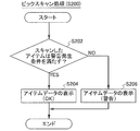
制御部20は、アクセスアンテナAAで受信したデータがピックリストデータである場合(図13のS30:YES;ピックリストデータ)、受信したピックリストデータが示す条件に該当するアイテムが在庫データベース232に含まれているか否か判断する(S302)。ピックリストデータが示す条件に該当するアイテムは、保管庫1から出庫すべきアイテムである。S302において、例えば、ピックリストデータが示す条件が、アイテムコードとロット番号である場合、そのアイテムコードとロット番号をキーとして在庫データベース232を検索し、一致するものがあるか否か判断する。
ピックリストデータが示す条件に該当するアイテムが在庫データベース232に含まれていない場合には(S302:NO)、正常終了メッセージを表示して(S304)、終了する。
ピックリストデータが示す条件に該当するアイテムが在庫データベース232に含まれている場合には(S302:YES)、S306以降の処理が実行される。制御部20は先ず、所定のメッセージが表示パネル22aに表示されるように表示部22を制御して(S306)、タイマを始動させる(S308)。S306で表示パネル22aに表示される所定のメッセージを含む画像例を図20に示す。図20の画像G30では、保管庫1から出庫すべきアイテムのリスト(各アイテムのアイテム名およびロット番号)を表示するとともに、当該アイテムを出庫させることをユーザに促すメッセージが表示される。
有効なユーザデータであると判断されると(S310:YES)、ドアロックが解除され(S312),ドア3を開状態としてユーザが出庫作業を行うことが可能となる。
制御部20は、ドア3がいったん閉状態から開状態となり再度閉状態となった場合には、出庫作業が終了したと判断し(S314:YES)、フルスキャンを実行して結果を表示パネル22aに表示する(S316)。すなわち、制御部20は、保管庫1内に保管されているすべてのアイテムに取り付けられているアイテムタグに記録されたデータを読み出す処理を行う。次いで制御部20は、保管庫1から全てのピックアイテムが出庫(回収)されたか否か判断する(S318)。
ピックリストデータが示す条件に該当するすべてのアイテムが保管庫1から出庫されるまでS306~S318の処理は繰り返される。但し、警告メッセージが出力されてから所定時間以内に有効なユーザデータを受信しない場合には(S322:YES)、警告メッセージを解除して(S324)終了し、通常動作に復帰する。S324において、所定時間内にユーザカードUCがアクセスアンテナ設置部10にかざされない場合に警告メッセージを解除するのは、他のユーザが緊急で保管庫1内のアイテムを取り出したい場合を考慮したためである。
次に、実施形態に係る保管庫1内のアイテムの有効期限の管理方法の好ましい例について、図21のフローチャートを参照して説明する。
この例では、ユーザによるトランザクションにおける警告発生条件(図15のS130参照)が、後述する判定結果によって条件M1または条件M2のいずれかに選択的に決定される。条件M1および条件M2は、以下のとおりである。
(条件M1)同一のアイテムコードのアイテムの中から有効期限までの期間が最短であるアイテム以外のアイテムを保管庫1から出庫すること
(条件M2)有効期限を過ぎたアイテム以外のアイテムを出庫すること
なお、S406の確認メッセージが出力されてから所定時間内に保管庫1がユーザデータを受信しない場合には(S408:NO)、S130(図15参照)の警告発生条件を条件M1とする(S410)。
そして、トランザクション処理(図15)において同一のアイテムコードのアイテムの中から有効期限までの期間が最短であるアイテム以外のアイテムが出庫された(つまり、条件M1を満たす)と判断された場合(S130:YES)、警告メッセージが出力される(S136)。このとき、所定時間内にユーザアクセス処理が再度実行され(S142:YES→S100)、トランザクション処理(図15)において、直近に出庫されたと判断されたアイテムが再び入庫された(つまり、保管庫1に戻された)場合には、S130では条件M1を満たさなくなった(S130:NO)と判断してもよい。つまり、S130の条件M1を満たすか否かは、S140で設定される所定時間内のアイテムの出庫結果によって判断される。当該所定時間内に、条件M1を満たすと判断されたアイテムが保管庫1に戻されなかった場合には(S140:YES)、制御部20はUSBインタフェース25を制御して、監督者のメールアドレスへ電子メールを送信する(S148)。
そして、トランザクション処理(図15)において有効期限を過ぎたアイテム以外のアイテムが出庫された(つまり、条件M2を満たす)と判断された場合(S130:YES)、警告メッセージが出力される(S136)。このとき、所定時間内にユーザアクセス処理が再度実行され(S142:YES→S100)、トランザクション処理(図15)において、直近に出庫されたと判断されたアイテムが再び入庫された(つまり、保管庫1に戻された)場合には、S130では条件M2を満たさなくなった(S130:NO)と判断してもよい。つまり、S130の条件M2を満たすか否かは、S140で設定される所定時間内のアイテムの出庫結果によって判断される。当該所定時間内に、条件M2を満たすと判断されたアイテムが保管庫1に戻されなかった場合には(S140:YES)、制御部20はUSBインタフェース25を制御して、監督者のメールアドレスへ電子メールを送信する(S148)。
他方、有効期限が切れたアイテムが存在する場合には、ユーザカードUCをかざすか否かの操作によって、警告発生条件を条件M1とした制御(第1モード。)、または、警告発生条件を条件M2とした制御(第2モード)のいずれかをユーザが選択できる。そのため、ユーザの目的に応じて、有効期限が切れたアイテムを除去することを優先するか、あるいは利用したいアイテムを出庫することを優先するか、ユーザが判断できる。よって、ユーザの保管庫1に対する誤使用防止を図ることができる。
(5-1)ピックスキャン
図15のトランザクション処理のフローチャートにおいて示したように、ユーザによるアイテムの入庫あるいは出庫の作業が終了(つまり、1回のトランザクションが終了)してドア3を閉状態とした場合に、フルスキャンが実行される。フルスキャンをドア3が閉状態となった後に実行するのは、以下の2つの理由による。すなわち、第1に、作業中にユーザは保管庫1からいったん取り出したアイテムを保管庫1内に戻すこともあるため、ドア3が閉状態になってトランザクションが終了したと判断した後でなければ保管庫1内のアイテムの正確な読み取りができないためである。第2に、ドア3を開状態の場合にフルスキャンを実行した場合、筐体2の外部の電波環境によっては通信性能が劣化する可能性があるためである。
そこで、ユーザは、待ち時間を短縮する、あるいは待ち時間を無くすためにピックスキャンを利用することができる。例えば、ユーザがトランザクションを実行中でドア3が開状態の場合、アイテムを保管庫1から出庫しようとするときには当該アイテムをアクセスアンテナ設置部10にかざして(つまり、ピックスキャンを行って)、適切なアイテムを出庫しようとしているか確認することができる。出庫されたアイテムの特定はフルスキャンの実行結果によって判断されるが、ピックスキャンによって適切なアイテムを出庫しようとすることが分かれば、ユーザは、ドア3を閉状態としてトランザクションを終了させた後に、フルスキャンの結果を待たずに直ちに保管庫1を離れることができる。そのため、特に少量のアイテムを取り出す用途でメリットがある。
ピックアイテムは、様々な場所に配置してある複数の保管庫1から出庫することが予定される。例えば、アイテムを薬品とした場合、様々な病院に設置されている保管庫1から特定の条件を満たすアイテムを出庫することが必要となる。そのような状況で、保管庫1がネットワークに繋がっていない状態で動作しているときに、各病院に設置されている複数の保管庫1の各々に保管されているすべてのアイテムを例えば紙に記載されたリストと照合して、ピックアイテムのみを目視で保管庫1から取り出すのは煩雑である。また、取り除くべき(つまり、出庫すべき)アイテムが保管庫1から全て取り除かれたのか作業者には直ちにわからない、という問題がある。
一方、本実施形態のピックリストカードでは、ピックアイテムを保管庫1の中から作業前に予め特定することができる。そのため、ピックアイテムが保管庫1に含まれていない場合には無駄な探索作業をしなくて済む。ピックアイテムが保管庫1に含まれている場合であっても探索の目標となるアイテムが予め分かっているため、ユーザはピックアイテムを比較的容易に保管庫1から取り出すことができる。特に様々な場所に保管庫1が設置されている場合、ユーザはピックリストカードのみを携えて保管庫1が設置されている場所を巡回し、すべてのピックアイテムを出庫することができる。すなわち、保管庫内の所望のアイテムを確実に取り出すことができる。
上述した実施形態では、ピックリスト処理において保管庫1から出庫すべきアイテムを特に限定していない。つまり、出庫すべきアイテムの条件は適宜設定することができる。例えば、特定の種類のアイテムが大量に必要となり各保管庫から集めている場合には、カードに内蔵するRFタグには、収集対象のアイテムの種類を特定するアイテムコードをアイテムの条件に関する情報を予め書き込んでおく。出庫すべきアイテムがリコールの対象となるアイテムである場合には、ピックリストデータとしてリコールの対象となるアイテムを特定可能な条件(例えば、アイテムコードとロット番号)についての情報が含まれる。
アイテムの条件に関する情報は、ユーザが保管庫1からアイテムを取り出すために、保管庫1内のアイテムのアイテムデータの検索条件とすることができる条件であれば如何なる情報であってもよい。例えば、アイテムデータは、対応するアイテムの名称、アイテムコード 、有効期限、ロット番号のうち少なくともいずれかを含むデータであり、アイテムの条件は、アイテムの名称、アイテムコード、有効期限、ロット番号のうち少なくともいずれかを含む条件であってもよい。
2…筐体
3…ドア
3a…ドアハンドル
4…キャスタ
10…アクセスアンテナ設置部
20…制御部
21…リーダユニット
22…表示部
22a…表示パネル
23…記憶部
231…登録ユーザデータベース
232…在庫データベース
233…トランザクションログデータベース
24…音声出力部
24a…スピーカ
25…USBインタフェース
26…LANインタフェース
27…センサ
28…ドアロック部
R…ラック群
R1~R7…ラック
P…仕切り板
RA…ラックアンテナ群
RA1~RA7…ラックアンテナ
AA…アクセスアンテナ
L…ラベル
IM1~IM6…アイテム
UC…ユーザカード
PC…ピックリストカード
Claims (8)
- アイテムに関するアイテム情報が記録されたRFタグである第1タグがアイテムごとに取り付けられた複数のアイテムを保管するための保管庫であって、
前記複数のアイテムを収容する筐体と、
前記筐体と連結して設けられ、前記筐体内の前記複数のアイテムに対する外部からのアクセスが可能となる開状態、または、前記筐体内の前記複数のアイテムに対する外部からのアクセスが遮断される閉状態のいずれかの状態となるドアと、
前記ドアが閉状態である場合に、前記筐体内に収容された全てのアイテムの第1タグに記録されているアイテム情報を読み出す第1リーダと、
前記ドアが開状態である場合に、第1タグが取り付けられたアイテムを前記筐体の外部から前記筐体上の所定の領域に近接させたときに、当該第1タグに記録されているアイテム情報を読み出す第2リーダと、
アイテム情報を記憶する記憶部と、
前記第1リーダによって読み出されたアイテム情報を前記記憶部に記憶させるとともに、前記第2リーダによって読み出されたアイテム情報が警告発生条件を満たすか否かの判定結果を、当該アイテム情報に基づいて、または、当該アイテム情報と前記記憶部が記憶するアイテム情報とを比較することによって決定する第1制御部と、
を備えた、保管庫。 - 前記第1制御部によって決定された前記判定結果を表示パネルに表示する表示部をさらに備えたことを特徴とする、
請求項1に記載された保管庫。 - 前記第1制御部によって決定された前記判定結果を音声出力する音声出力部をさらに備えたことを特徴とする、
請求項1または2に記載された保管庫。 - 前記第1リーダは、前記ドアが開状態から閉状態となったことを条件として前記筐体内に収容された全てのアイテムの第1タグに記録されているアイテム情報を読み出すことを特徴とする、
請求項1~3のいずれかに記載された保管庫。 - 前記アイテム情報は、対応するアイテムのアイテムコードと有効期限の情報を含み、
前記警告発生条件は、前記第2リーダによって読み出されたアイテム情報と、前記記憶部が最後に記憶したアイテム情報とに基づいて、前記所定の領域に近接させたアイテムが、前記筐体内に収容された同一のアイテムコードのアイテムのうち有効期限までの期間が最短ではないアイテムである、若しくは有効期限が切れたアイテムであると判断したことである、
請求項4に記載された保管庫。 - 前記ドアを開錠または施錠するドアロック部と、
前記ドアロック部を制御する第2制御部と、をさらに備え、
前記ドアが閉状態である場合、前記第2リーダは、ユーザを識別するユーザ識別情報が記録された第2タグを、前記筐体の外部から前記筐体の前記所定の領域に近接させたとき、前記第2タグに記録されているユーザ識別情報を読み出し、
前記第2制御部は、前記第2リーダによって読み出されたユーザ識別情報の認証が成功した場合に、前記ドアが開錠されるように前記ドアロック部を制御することを特徴とする、
請求項1~5のいずれかに記載された保管庫。 - 前記表示パネルと前記所定の領域とが近接した位置に配置されていることを特徴とする、
請求項2に記載された保管庫。 - 前記アイテム情報は、対応するアイテムの名称、アイテムコード、有効期限、ロット番号のうち少なくともいずれかの情報を含むことを特徴とする、
請求項1~7のいずれかに記載された保管庫。
Priority Applications (7)
| Application Number | Priority Date | Filing Date | Title |
|---|---|---|---|
| EP16786555.9A EP3291154A1 (en) | 2015-04-28 | 2016-04-28 | Storage cabinet |
| JP2017515604A JP7057131B2 (ja) | 2015-04-28 | 2016-04-28 | 保管庫、保管方法 |
| US15/565,830 US10504058B2 (en) | 2015-04-28 | 2016-04-28 | Storage cabinet |
| AU2016255237A AU2016255237B2 (en) | 2015-04-28 | 2016-04-28 | Storage cabinet |
| CN202010686063.2A CN112009933B (zh) | 2015-04-28 | 2016-04-28 | 保管库 |
| CN201680020082.3A CN107531416B (zh) | 2015-04-28 | 2016-04-28 | 保管库 |
| US16/675,402 US10949802B2 (en) | 2015-04-28 | 2019-11-06 | Storage cabinet |
Applications Claiming Priority (2)
| Application Number | Priority Date | Filing Date | Title |
|---|---|---|---|
| JP2015091124 | 2015-04-28 | ||
| JP2015-091124 | 2015-04-28 |
Related Child Applications (2)
| Application Number | Title | Priority Date | Filing Date |
|---|---|---|---|
| US15/565,830 A-371-Of-International US10504058B2 (en) | 2015-04-28 | 2016-04-28 | Storage cabinet |
| US16/675,402 Continuation US10949802B2 (en) | 2015-04-28 | 2019-11-06 | Storage cabinet |
Publications (1)
| Publication Number | Publication Date |
|---|---|
| WO2016175279A1 true WO2016175279A1 (ja) | 2016-11-03 |
Family
ID=57198468
Family Applications (1)
| Application Number | Title | Priority Date | Filing Date |
|---|---|---|---|
| PCT/JP2016/063338 Ceased WO2016175279A1 (ja) | 2015-04-28 | 2016-04-28 | 保管庫 |
Country Status (6)
| Country | Link |
|---|---|
| US (2) | US10504058B2 (ja) |
| EP (1) | EP3291154A1 (ja) |
| JP (1) | JP7057131B2 (ja) |
| CN (2) | CN107531416B (ja) |
| AU (1) | AU2016255237B2 (ja) |
| WO (1) | WO2016175279A1 (ja) |
Families Citing this family (7)
| Publication number | Priority date | Publication date | Assignee | Title |
|---|---|---|---|---|
| PT1624891E (pt) | 2003-05-06 | 2010-01-05 | Syntonix Pharmaceuticals Inc | Proteínas quiméricas de factor de coagulação-fc destinadas ao tratamento da hemofilia |
| US10504058B2 (en) * | 2015-04-28 | 2019-12-10 | Sato Holdings Kabushiki Kaisha | Storage cabinet |
| US10704294B1 (en) * | 2017-04-17 | 2020-07-07 | Lockheed Martin Corporation | Wirelessly actuated cover for a structure |
| WO2020031499A1 (ja) | 2018-08-10 | 2020-02-13 | Phcホールディングス株式会社 | 薬品管理システム |
| CN110210590A (zh) * | 2019-06-05 | 2019-09-06 | 杭州智测自动化科技有限公司 | 储物柜中物品的存取方法及装置、电子设备、存储介质 |
| CN114365146A (zh) * | 2019-06-28 | 2022-04-15 | 实耐宝公司 | 在工具仓库管理系统中管理的自动化工具控制设备 |
| CN115376250A (zh) * | 2022-08-16 | 2022-11-22 | 广东电网有限责任公司东莞供电局 | 一种联网版智能存取柜 |
Citations (4)
| Publication number | Priority date | Publication date | Assignee | Title |
|---|---|---|---|---|
| JPH10316210A (ja) * | 1997-05-21 | 1998-12-02 | Hitachi Ltd | 保管庫 |
| JP2002119577A (ja) * | 2000-06-28 | 2002-04-23 | Atsushi Kinoshita | 医療物品、特にカテーテルの管理システム |
| JP2005082381A (ja) * | 2003-09-11 | 2005-03-31 | Tohken Co Ltd | Rfidタグを用いた物品管理システム |
| WO2006093701A1 (en) * | 2005-02-25 | 2006-09-08 | Cisco Technology, Inc. | Methods and devices for providing alerts for spoilage and hazardous combinations |
Family Cites Families (27)
| Publication number | Priority date | Publication date | Assignee | Title |
|---|---|---|---|---|
| JP2001317862A (ja) * | 2000-02-28 | 2001-11-16 | Dainippon Printing Co Ltd | 食品の自動冷蔵システムと冷蔵庫 |
| US20020183882A1 (en) | 2000-10-20 | 2002-12-05 | Michael Dearing | RF point of sale and delivery method and system using communication with remote computer and having features to read a large number of RF tags |
| DE60144402D1 (de) | 2000-10-20 | 2011-05-19 | Promega Corp | Hochfrequenzidenfikationsverfahren und System zum Verteilen von Produkten |
| US6707381B1 (en) * | 2001-06-26 | 2004-03-16 | Key-Trak, Inc. | Object tracking method and system with object identification and verification |
| US6989749B2 (en) * | 2003-11-21 | 2006-01-24 | The United States Of America As Represented By The Secretary Of The Navy | Electronic check out system |
| US7348884B2 (en) * | 2004-07-29 | 2008-03-25 | Omnicell, Inc. | RFID cabinet |
| ITPN20050075A1 (it) * | 2005-10-20 | 2007-04-21 | Electrolux Professional Spa | Metodo per monitorare articoli in un frigo |
| US8095435B2 (en) | 2005-11-08 | 2012-01-10 | American Airlines, Inc. | Method to effectuate point of use control and accountability of monitored articles |
| WO2007064816A2 (en) * | 2005-12-02 | 2007-06-07 | Asd Specialty Healthcare, Inc. D/B/A Amerisourcebergen Specialty Group | System and method for pharmaceutical management and tracking |
| US7775056B2 (en) * | 2006-01-18 | 2010-08-17 | Merck Sharp & Dohme Corp. | Intelligent refrigerator for storing pharmaceutical product containers |
| KR20070078939A (ko) * | 2006-01-31 | 2007-08-03 | 박성미 | 주방 관리 장치 및 이를 이용한 식품 관리 방법 |
| US20070205894A1 (en) * | 2006-03-01 | 2007-09-06 | Sun Microsystems, Inc. | Radio frequency identification for asset management |
| CN101071411A (zh) * | 2006-05-12 | 2007-11-14 | 泰州乐金电子冷机有限公司 | 利用rfid的食品管理冰箱 |
| US7932824B2 (en) * | 2006-10-13 | 2011-04-26 | RFID Mexico, S.A. DE C.V. | Item tracking system |
| US7710275B2 (en) | 2007-03-16 | 2010-05-04 | Promega Corporation | RFID reader enclosure and man-o-war RFID reader system |
| US9041508B2 (en) * | 2008-08-08 | 2015-05-26 | Snap-On Incorporated | Image-based inventory control system and method |
| US8020768B2 (en) * | 2009-04-01 | 2011-09-20 | RFID Mexico, S.A. DE C.V. | Portable container inventory control system |
| US8659397B2 (en) * | 2010-07-22 | 2014-02-25 | Vocollect, Inc. | Method and system for correctly identifying specific RFID tags |
| FR2988936B1 (fr) | 2012-03-30 | 2019-05-24 | Biolog-id | Procede de qualification de conteneur, enceinte de stockage associee |
| JP6095293B2 (ja) | 2012-08-10 | 2017-03-15 | シャープ株式会社 | 保管庫、および保管システム |
| US20140138340A1 (en) * | 2012-11-19 | 2014-05-22 | Robert W. Miller | Overhead Hoist |
| KR102110578B1 (ko) * | 2012-11-19 | 2020-05-13 | 옴니셀 인코포레이티드 | 다수의 rfid 리더를 이용한 저장 캐비넷 |
| CN203012785U (zh) * | 2012-12-20 | 2013-06-19 | 杭州钱杭信息科技有限公司 | 基于rfid可识别数字化标签的临床用血液管理系统 |
| CN204132804U (zh) * | 2013-12-13 | 2015-02-04 | 戴淑娟 | 具有药品有效期提示功能的药品柜 |
| US10504058B2 (en) * | 2015-04-28 | 2019-12-10 | Sato Holdings Kabushiki Kaisha | Storage cabinet |
| FR3047185B1 (fr) | 2016-10-03 | 2021-01-29 | Biolog | Dispositif de stockage d'elements |
| FR3047184A1 (fr) | 2016-10-03 | 2017-08-04 | Biolog | Dispositif de stockage d'elements |
-
2016
- 2016-04-28 US US15/565,830 patent/US10504058B2/en active Active
- 2016-04-28 JP JP2017515604A patent/JP7057131B2/ja active Active
- 2016-04-28 EP EP16786555.9A patent/EP3291154A1/en active Pending
- 2016-04-28 CN CN201680020082.3A patent/CN107531416B/zh active Active
- 2016-04-28 CN CN202010686063.2A patent/CN112009933B/zh active Active
- 2016-04-28 AU AU2016255237A patent/AU2016255237B2/en active Active
- 2016-04-28 WO PCT/JP2016/063338 patent/WO2016175279A1/ja not_active Ceased
-
2019
- 2019-11-06 US US16/675,402 patent/US10949802B2/en active Active
Patent Citations (4)
| Publication number | Priority date | Publication date | Assignee | Title |
|---|---|---|---|---|
| JPH10316210A (ja) * | 1997-05-21 | 1998-12-02 | Hitachi Ltd | 保管庫 |
| JP2002119577A (ja) * | 2000-06-28 | 2002-04-23 | Atsushi Kinoshita | 医療物品、特にカテーテルの管理システム |
| JP2005082381A (ja) * | 2003-09-11 | 2005-03-31 | Tohken Co Ltd | Rfidタグを用いた物品管理システム |
| WO2006093701A1 (en) * | 2005-02-25 | 2006-09-08 | Cisco Technology, Inc. | Methods and devices for providing alerts for spoilage and hazardous combinations |
Non-Patent Citations (1)
| Title |
|---|
| See also references of EP3291154A4 * |
Also Published As
| Publication number | Publication date |
|---|---|
| JPWO2016175279A1 (ja) | 2018-02-22 |
| AU2016255237B2 (en) | 2020-11-26 |
| CN107531416A (zh) | 2018-01-02 |
| EP3291154A4 (en) | 2018-03-07 |
| AU2016255237A1 (en) | 2017-11-02 |
| US20180114181A1 (en) | 2018-04-26 |
| EP3291154A1 (en) | 2018-03-07 |
| US20200074392A1 (en) | 2020-03-05 |
| CN107531416B (zh) | 2020-08-21 |
| US10504058B2 (en) | 2019-12-10 |
| JP7057131B2 (ja) | 2022-04-19 |
| CN112009933A (zh) | 2020-12-01 |
| CN112009933B (zh) | 2022-04-19 |
| US10949802B2 (en) | 2021-03-16 |
Similar Documents
| Publication | Publication Date | Title |
|---|---|---|
| JP7057131B2 (ja) | 保管庫、保管方法 | |
| JP6712263B2 (ja) | 保管庫、保管方法 | |
| JP6712264B2 (ja) | 保管庫、保管方法 | |
| CN102498494B (zh) | 库存监控和核实系统 | |
| JP6655311B2 (ja) | 情報処理システム | |
| JP2012533118A (ja) | 自動化された医療用品の取り出し/保管追跡方法および装置 | |
| KR20170074971A (ko) | 인벤토리 관리 시스템 및 사용 방법 | |
| KR20190090877A (ko) | 다수의 rfid 리더를 이용한 저장 캐비넷 | |
| WO2014046760A1 (en) | Mobile retail peripheral platform for handheld devices | |
| JP7057424B2 (ja) | 薬品管理システム | |
| JP2010238088A (ja) | 資産管理システムおよび携帯資産管理装置 | |
| JP6486786B2 (ja) | 情報処理システム、保管庫 |
Legal Events
| Date | Code | Title | Description |
|---|---|---|---|
| 121 | Ep: the epo has been informed by wipo that ep was designated in this application |
Ref document number: 16786555 Country of ref document: EP Kind code of ref document: A1 |
|
| WWE | Wipo information: entry into national phase |
Ref document number: 15565830 Country of ref document: US |
|
| ENP | Entry into the national phase |
Ref document number: 2017515604 Country of ref document: JP Kind code of ref document: A |
|
| NENP | Non-entry into the national phase |
Ref country code: DE |
|
| ENP | Entry into the national phase |
Ref document number: 2016255237 Country of ref document: AU Date of ref document: 20160428 Kind code of ref document: A |