WO2016178264A1 - Plaque de séparation et matériau de rembourrage - Google Patents
Plaque de séparation et matériau de rembourrage Download PDFInfo
- Publication number
- WO2016178264A1 WO2016178264A1 PCT/JP2015/063067 JP2015063067W WO2016178264A1 WO 2016178264 A1 WO2016178264 A1 WO 2016178264A1 JP 2015063067 W JP2015063067 W JP 2015063067W WO 2016178264 A1 WO2016178264 A1 WO 2016178264A1
- Authority
- WO
- WIPO (PCT)
- Prior art keywords
- groove
- partition plate
- opening
- protrusion
- height
- Prior art date
- Legal status (The legal status is an assumption and is not a legal conclusion. Google has not performed a legal analysis and makes no representation as to the accuracy of the status listed.)
- Ceased
Links
Images


Classifications
-
- B—PERFORMING OPERATIONS; TRANSPORTING
- B65—CONVEYING; PACKING; STORING; HANDLING THIN OR FILAMENTARY MATERIAL
- B65D—CONTAINERS FOR STORAGE OR TRANSPORT OF ARTICLES OR MATERIALS, e.g. BAGS, BARRELS, BOTTLES, BOXES, CANS, CARTONS, CRATES, DRUMS, JARS, TANKS, HOPPERS, FORWARDING CONTAINERS; ACCESSORIES, CLOSURES, OR FITTINGS THEREFOR; PACKAGING ELEMENTS; PACKAGES
- B65D81/00—Containers, packaging elements, or packages, for contents presenting particular transport or storage problems, or adapted to be used for non-packaging purposes after removal of contents
- B65D81/02—Containers, packaging elements, or packages, for contents presenting particular transport or storage problems, or adapted to be used for non-packaging purposes after removal of contents specially adapted to protect contents from mechanical damage
Definitions
- the present invention relates to a cushioning material obtained by assembling a partition plate and the partition plate.
- a cushioning material When packaging an article, a cushioning material is often used in which a partition plate having a downward groove and a partition plate having an upward groove are assembled so that the grooves are engaged with each other and assembled in a cross-beam shape.
- Patent Document 1 There is a proposal of a cushioning material using a low foam material or plastic corrugated cardboard as such a partition plate (Patent Document 1, Patent Document 2).
- the cushioning material described in Patent Document 1 uses a first partition plate in which a U-shaped cut is formed and a second partition plate in which an end is cut from above and below, so that the type of component There is a problem that increases.
- the material is limited to plastic cardboard.
- the cushioning material described in Patent Document 2 has a structure in which the same type of partition plates having a plurality of linear grooves are combined with each other, so that the types of parts are not increased and the assembly is easy, but it is prevented from coming off. Therefore, it is necessary to heat-seal the bottom plate. After all, the number of parts and the ease of assembly work cannot be achieved. There is also a problem that once assembled, it cannot be disassembled.
- an object of the present invention is to provide a cushioning material that can be easily assembled and disassembled without increasing the types of parts, and from which a partition plate does not come off carelessly after assembly.
- the partition plate of the present invention is characterized in that a groove portion formed so as to have an opening on one of the upper and lower sides has the following configuration.
- the groove portion is formed such that a depth from the opening to the groove bottom is larger than 1 ⁇ 2 of the height of the partition plate, and the groove portion is formed between the opening and the groove bottom. Projecting from both the left and right groove sidewalls so as to project from the groove bottom to a position on the opening side of the height of half of the partition plate.
- the groove includes a vertical portion having substantially the same width as the partition plate between the protrusion and the opening, and the vertical portion extends from the protrusion to the groove bottom. A width that does not protrude inward from the extension line of the first and a depth that allows the protrusion to be accommodated.
- a plurality of partition plates of the present invention are prepared, and when assembled in a cross-beam shape by shifting 90 degrees upside down so as to mesh each other's grooves, a partition plate meshed from above (hereinafter referred to as “upper partition plate”) And the projections of a partition plate (hereinafter referred to as “lower partition plate”) engaged from below are brought into contact with each other at the outer corners.
- upper partition plate a partition plate meshed from above
- lower partition plate the projections of a partition plate engaged from below
- each partition plate has a configuration in which the depth of the groove and the position of the protrusion are described in (1A), and the width and depth from the protrusion to the groove bottom are described in (1B). Therefore, the protrusions are accommodated in the groove bottom portion with the other protrusions crossing each other. Moreover, since it has the linear part as described in (1B) between the protrusion part and the opening, the vertical part of each groove part serves as a guide for the outer surface of the other partition plate, and aligns the meshing direction, After engaging, the partition plate is prevented from falling.
- the protrusion position of a projection part has the structure as described in (1A), and the width and height from a protrusion part to a groove bottom have the structure as described in (1B), it is an upper partition.
- the projections of the plate are located below the projections of the lower partition plate, the horizontal surfaces of the projections of the lower partition plate are located above the upper partition plate, and prevent each other from coming out. Become. Thereby, the partition plate after an assembly does not remove carelessly. Although it does not come off inadvertently in this way, the partition plates are not separated from each other, and can be disassembled if the partition plate is intentionally extracted.
- the partition plate of the present invention is characterized in that a groove portion formed so as to have an opening on one of the upper and lower sides has the following configuration.
- the groove portion is formed so that a depth from the opening to the groove bottom is larger than 1 ⁇ 2 of a height of the partition plate, and the groove portion is formed in the groove between the opening and the groove bottom.
- the protruding portion is a tapered surface having a slope whose height increases as the groove bottom side is a horizontal plane and the opening side is away from the groove center, and the horizontal plane is a height of the partition plate from the groove bottom.
- the groove includes a vertical portion having a width substantially the same as the thickness of the partition plate between the protrusion and the opening.
- the space from the protrusion to the groove bottom has a width that does not protrude inward from the extension line of the vertical portion and a depth that allows the protrusion to be accommodated.
- a plurality of partition plates of the present invention are prepared, and when assembled in a cross-beam shape by shifting 90 degrees upside down so as to mesh each other's grooves, a partition plate meshed from above (hereinafter referred to as “upper partition plate”) And the inclined surface of the protruding portion of the partition plate (hereinafter referred to as “lower partition plate”) meshed from below are in contact with each other at the outer corners. If the partition plates that contact the outer corners of the projections are pushed in so as to engage more deeply, the outer corners of the projections are slightly deformed along the other inclined surface. Invade toward the other side of the groove.
- each partition plate has a configuration of (2A) in the groove portion and a (2D) configuration from the projection portion to the bottom of the groove, so that the projection portion crosses the other projection portion. And stored in the bottom of the groove.
- the vertical portion of each groove serves as a guide for the outer surface of the other partition plate, aligns the meshing direction, and after meshing Prevents the divider from falling over.
- a projection part has the structure of (2B)
- the horizontal surface of the projection part of an upper partition plate is above the horizontal surface of the projection part of a lower partition plate, and the projection part of a lower partition plate
- the horizontal plane is located above the horizontal plane of the protrusion of the upper partition plate and is in a state in which the other party is prevented from coming out.
- the partition plate of the present invention may further include the following configuration.
- (3) The groove is formed so that the groove side wall is symmetrical.
- partition plates of the present invention may further include the following configuration. (4) A tapered surface that opens outward is formed on the opening side of the vertical portion.
- the partition plates can be engaged with each other from a slightly oblique direction, or the partition plates can be slightly pulled out in a slightly oblique direction. Can be easily.
- the cushioning material of the present invention which has been made to achieve the above object, is a cushioning material that is assembled in a grid pattern so that a plurality of partition plates having grooves formed on one side of the upper and lower sides are meshed with each other.
- each of the plurality of partition plates has the following configuration.
- the partition plate is made of foamed plastic, and the groove has groove sidewalls that are symmetrical.
- the groove portion is formed so that a depth from the opening to the groove bottom is larger than 1 ⁇ 2 of the height of the partition plate, and the groove portion is formed between the opening and the groove bottom.
- the protrusion is a tapered surface having a slope whose height increases as the groove bottom side is a horizontal plane and the opening side is away from the groove center.
- the horizontal plane is a height of the partition plate from the groove bottom. It protrudes from both of the left and right groove sidewalls so as to protrude to a position at a height that is closer to the opening side than 1/2.
- the groove includes a vertical portion having substantially the same width as the partition plate between the protrusion and the opening.
- the space from the protrusion to the groove bottom has a width that does not protrude inward from the extension line of the vertical portion and a depth that allows the protrusion to be accommodated.
- a tapered surface that opens outward is formed on the opening side of the vertical portion.
- the partition plate formed of foamed plastic can deform the projection during assembly / disassembly, but the projection is restored to its original shape in the assembled state.
- the partition plate can also be manufactured by a method of punching by Thomson punching using a commercially available low foaming extruded sheet material having a foaming ratio of 2 to 8 times and a plate thickness of 10 mm to 20 mm.
- the foamed plastic sheet material is punched with a Thomson die, it is desirable to set the thickness to 3 mm or more in consideration of automatically discharging the punched portion from the die.
- a low foam material low foam polypropylene, low foam polystyrene, etc.
- the partition plate for buffer materials which has a desired function can be manufactured using a Thomson die.
- the present invention it is possible to provide a cushioning material that can be easily assembled and disassembled without increasing the types of parts, and prevents the partition plate from being unintentionally detached after assembly.
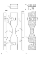
- Example 1 shows a partition plate of Example 1,
- A is a six-sided view in which a rear view and a left side view are omitted,
- B is an aa sectional view, and
- C is a bb sectional view.
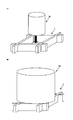
- the mode that the partition plate of Example 1 is assembled and it is set as a buffer material is shown,
- A) is a perspective view of a partition plate,
- B) is a perspective view of the buffer material in the middle of an assembly,
- (B) is the buffer material after completion of an assembly.
- the shock absorbing material formed by assembling the partition plate of Example 1 is shown, (A) is a plan view, (B) is a cc enlarged sectional view, (C) is a dd enlarged sectional view, and (D) is e. -E is an enlarged sectional view.
- the usage example of the shock absorbing material of Example 1 is shown, (A) is a perspective view of a mode that an article is stored and used between the meshes as a partition, and (B) is used by placing the article on the upper surface as a cradle. It is a perspective view which shows a mode.
- the partition plate of Example 2 is shown, (A) is a six-sided view in which the rear view and the left side view are omitted, (B) is an ff sectional view, and (C) is a gg sectional view.
- the usage example of the shock absorbing material which assembled the partition plate of Example 2 is shown, (A) is a perspective view before an assembly, (B) is a perspective view which shows a mode that it uses as a cradle for mounting a spherical article after completion of an assembly. It is.
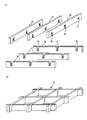
- the mode that the partition plate of Example 3 is assembled and it is set as a shock absorbing material is shown, (A) is a perspective view before an assembly, (B) is a perspective view after the completion of an assembly.
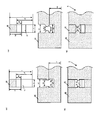
- the usage example of the buffer material of Example 3 is shown, (A) is a perspective view of a mode that the article is stored and used between the meshes as a partition, and (B) is used by placing the article on the upper surface as a cradle. It is a perspective view which shows a mode. Another example is shown, (A) is an enlarged cross-sectional view of the main part before assembly of Example 4, (B) is an enlarged cross-sectional view of the main part after completion of assembly of Example 3, and (C) is that of Example 4. The principal part expanded sectional view before an assembly is shown, (D) is the principal part expanded sectional view after the assembly of Example 5 is completed.
- FIG. 1A is a six-sided view in which a rear view and a left side view are omitted
- FIG. 1B is a cross-sectional view along aa
- FIG. b shows a cross-sectional view.
- the partition plate 10 includes groove portions 20 and 20 formed so that the upper side is the opening 21.
- the groove portions 20 and 20 have the same shape, and are formed such that the depth d1 from the opening 21 to the groove bottom 22 is larger than 1 ⁇ 2 of the height h of the partition plate 10.
- Protrusions 30 and 30 projecting into the groove are provided at positions between the bottom 22.
- the protrusion 30 is a tapered surface 32 having a slope that increases in height as the groove bottom 22 side is a horizontal plane 31 and the opening 21 side is away from the groove center. It protrudes from both the left and right groove side walls 23 and 24 so as to protrude to the position of the height h1 that is closer to the opening 21 than 1/2 of the height h.
- the groove portions 20 and 20 are also provided with vertical portions 25 and 26 having a width b1 substantially equal to the plate thickness t of the partition plate 10 between the protrusion portions 30 and 30 to the opening 21. And between the protrusions 30 and 30 to the groove bottom 22, a width b2 that does not protrude inward from the extension line of the vertical parts 25 and 26, and a depth d2 that can store the protrusions 30 and 30 ,have. Furthermore, tapered surfaces 27 and 28 that are outwardly opened are formed on the opening 21 side of the vertical portions 25 and 26. As shown in the drawing, the groove portions 20 and 20 of the partition plate 10 are formed so that the groove side walls 23 and 24 are of the same shape with left-right symmetry.
- a low-foaming PP sheet manufactured by Mitsui Chemicals Tosero Co., Ltd., product name: Palonia (registered trademark), polypropylene triple-extrusion foamed sheet
- t 10 mm
- h 30 mm
- d1 21 mm
- h1 15.5 mm
- d2 6.5 mm.
- b3 6 in this embodiment so that the tip of the protrusion 30 is chamfered vertically and the gap b3 between the left and right protrusions is within a range of 50% to 80% with respect to the plate thickness t. .2 mm (62% of t).
- FIG. 2 (B) As shown in FIG. 2 (B), four partition plates 10 of this embodiment are prepared, and are assembled in a cross-beam shape by shifting them 90 degrees upside down so as to engage each other.
- the cushioning material 1 shown in C) is used for packaging.
- partition plate 11 the inclined surface of the projection 30 of the partition plate
- partition plate 12 the projection 30 of the partition plate meshed from below.
- each partition plate 11, 12 is formed so that the groove portion 20 is “a depth d 1 from the opening 21 to the groove bottom 22 is greater than 1 ⁇ 2 of the height h of the partition plate 11 (12)”.
- a width b2 that does not protrude inward from the extension line of the vertical portions 25 and 26 and a depth d2 that can accommodate the protrusion 30. Therefore, as shown in FIGS. 3 (B) and 3 (C), the protrusions 30 are accommodated in the groove bottom portion on the other side with the other protrusions 30 crossing each other.
- the vertical portions 25 and 26 having substantially the same width b1 as the plate thickness t of the partition plate 11 (12) are provided between the protruding portion 30 and the opening 21, the vertical portions 25 of the respective groove portions 20 are provided. , 26 serve as a guide for the outer surface of the other partition plate 11 (12), aligning the meshing direction, and preventing the partition plate 11 (12) from falling after meshing.
- the protrusion 30 is formed as “a taper surface 32 having a slope that increases in height as the groove bottom 22 side becomes the horizontal plane 31 and the opening 21 side is away from the groove center, and the horizontal plane 31 extends from the groove bottom 22 to the partition plate.
- 11 (12) protrudes from both the left and right groove sidewalls 23 and 24 so as to protrude to the position of the height h1 on the opening 21 side than 1/2 of the height h of FIG. 3 (12).
- the horizontal surface 31 of the protrusion 30 of the upper partition plate 11 is the horizontal surface 31 of the protrusion 30 of the lower partition plate 12, and the horizontal surface 31 of the lower protrusion 30 is the upper protrusion. It is located on the horizontal surface 31 of the part 30, and in this state, the outer corners 35 overlap with each other to prevent each other from coming out.
- partition plate 11 and partition plate 12 This prevents the assembled partition plate 11 and partition plate 12 from being inadvertently detached. Although it does not come off inadvertently in this way, the partition plates are not separated from each other, and can be disassembled if the partition plate 11 (12) is intentionally extracted.
- the groove side walls 23 and 24 are symmetric, the deformation of the protrusion 30 occurs almost symmetrically, and the engagement between the horizontal surfaces 31 in the assembled state is also symmetric. The work can be performed smoothly and the effect of preventing the removal in the assembled state is also exhibited appropriately.
- the partition plates can be slightly engaged from each other in an oblique direction, or the partition plates can be slightly pulled out in an oblique direction, Assembly work and disassembly work can be further facilitated.
- the cushioning material 1 of the present embodiment is formed of a low foam material, it has appropriate hardness and cushioning properties. As a result, as shown in FIG. 4A, the article W2 is placed on the upper surface as shown in FIG. It can also be used as a cradle to be placed. In addition, since the cushioning material 1 of this embodiment is easy to assemble and disassemble, it is transported to the packing site in a disassembled state, and after unpacking, it is disassembled again and transported to a material warehouse or another site. can do.
- FIG. 5 (A) is a six-side view in which the rear view and the left side view are omitted
- FIG. 5 (B) is a sectional view taken along line ff
- FIG. g shows a cross-sectional view.
- the partition plate 40 has the same material, t, h, h1, d1, d2, b1, and b2 dimensions as in the first embodiment, and the groove 20 has the same dimensions and shape as in the first embodiment.
- arc-shaped concave portions 41 and 42 are provided at the center portions of the upper surface and the lower surface, respectively.
- FIG. 6 (A) four partition plates 40 of the present embodiment are prepared and shifted 90 degrees upside down so as to mesh with each other, and assembled into a cross-beam shape as shown in FIG. It is used for packaging and packing as the cushioning material 2 shown in B). Since the shock-absorbing material 2 of Example 2 is provided with arc-shaped concave portions 41 and 42 on the upper surface when assembled in a cross-beam shape, it can be used as a cradle for placing a spherical article W3.
- FIG. 7A is a perspective view before assembly of the cushioning material 3 of Example 3, and FIG. 7B is a perspective view after completion of assembly.
- the partition plate 10 including the two groove portions 20 is used in the cushioning material 1 of the first embodiment.
- the buffer material 3 of the third embodiment is different in that the partition plate 50 including the three groove portions 20 at equal intervals is used.
- the cushioning material 3 of Example 3 is provided with four cells by assembling a total of six partition plates 50 in the same manner as in Example 1, three on the upper side and three on the lower side. It is assembled.
- the material and the dimensions of each groove 20 are the same as those in the first embodiment.
- the cushioning material 3 of the present embodiment can be used as a partition for storing the articles W3a to w3d between the meshes assembled in the form of a cross girder, as shown in FIG. 8 (B). As shown, it can also be used as a cradle for placing the article W4 on the upper surface.
- Example 4 is a cushioning material 4 that employs partition plates 61 and 62 having rectangular cross-section protrusions 71 and 72 as protrusions, as shown in FIGS. 9 (A) and 9 (B).
- the dimensions of the material, t, h, h1, d1, d2, b1, b2 are the same as in Example 1, but the gap b4 between the protrusions is 80% of the plate thickness t.
- the projection 71 of the upper partition plate 61 and the projection 72 of the lower partition plate 62 abut each other at the outer corners, and the other storage portion is slightly deformed. It is stored in.
- the protrusion part 71 and the protrusion part 72 prevent inadvertent pull-out at the outer corners. Further, at the time of disassembly, the outer corner of the projection 71 and the outer corner of the projection 72 that functioned as prevention of slipping out are slightly deformed, so that slipping out is not hindered in intentional disassembly work.
- Example 5 is a cushioning material 5 that employs partition plates 81 and 82 having semicircular cross-sectional protrusions 91 and 92 as protrusions, as shown in FIGS. 9 (C) and (D).
- the dimensions of the material, t, h, h1, d1, d2, b1, b2 are the same as in Example 1, but the gap b5 between the protrusions is 50% of the plate thickness t.
- the protruding portion 91 of the upper partition plate 81 and the protruding portion 92 of the lower partition plate 82 are in contact with each other at the outer corners, and the other storage portion is slightly deformed. It is stored in.
- the protruding portion 91 and the protruding portion 92 prevent inadvertent withdrawal at the outer corners. Further, at the time of disassembly, the outer corners of the protrusion 91 and the outer corners of the protrusion 92 that functioned as a prevention of slipping out are slightly deformed, so that the pulling out is not hindered in the intentional disassembly work.
- each embodiment it is possible to provide a cushioning material that can be easily assembled and disassembled without increasing the types of components and that prevents the partition plate from being inadvertently removed after assembly. .
- a low foaming PP sheet a low foaming polyester sheet may be used, and the foaming magnification and the plate thickness are not limited to those of the example, and when used as a cradle, Of the foamed plastics having an expansion ratio of 2 to 8 times and a plate thickness of 3 to 20 mm, those having hardness and cushioning properties suitable for the object to be packaged and packed may be adopted.
- the present invention is not limited to the packaging / packaging cushioning material, and can be used for various uses other than packaging / packaging, for example, installed under a floor board as a cushioning material for a floor having cushioning properties.
Landscapes
- Engineering & Computer Science (AREA)
- Mechanical Engineering (AREA)
- Buffer Packaging (AREA)
Abstract
La présente invention concerne un matériau de rembourrage qui peut être facilement monté et démonté dans la mesure où il n'y a pas d'augmentation du nombre de types de pièces et qui présente une plaque de séparation disposée de manière à ne pas être détachée par inadvertance après le montage du matériau de rembourrage. Des rainures (20) de cette plaque de séparation (10) répondent chacune à l'exigence "1/2 (hauteur h de plaque de séparation)" < "profondeur d1", et sont chacune pourvues de saillies (30) faisant saillie à l'intérieur de la rainure. Les saillies (30) font saillie de manière symétrique depuis les parois gauche et droite (23, 24) de manière à présenter des surfaces horizontales du côté fond de rainure (31) faisant saillie à un emplacement de la hauteur h1 qui est plus proche de l'ouverture que la moitié de [hauteur h de plaque de séparation] à partir du fond de la rainure. Des sections verticales (25, 26) présentant chacune une largeur b1 sensiblement égale à l'"épaisseur de plaque t de plaque de séparation" sont prévues entre les saillies et une ouverture. Une section entre les saillies et le fond de la rainure présente une largeur b2 de manière à ne pas faire saillie au-delà des lignes d'extension des sections verticales, et une profondeur d2 suffisamment grande pour loger les saillies (30). Des surfaces coniques s'ouvrant vers l'extérieur (27, 28) sont également formées au niveau du côté de l'ouverture.
Priority Applications (2)
| Application Number | Priority Date | Filing Date | Title |
|---|---|---|---|
| PCT/JP2015/063067 WO2016178264A1 (fr) | 2015-05-01 | 2015-05-01 | Plaque de séparation et matériau de rembourrage |
| JP2015539988A JP5846522B1 (ja) | 2015-05-01 | 2015-05-01 | 仕切板及び緩衝材 |
Applications Claiming Priority (1)
| Application Number | Priority Date | Filing Date | Title |
|---|---|---|---|
| PCT/JP2015/063067 WO2016178264A1 (fr) | 2015-05-01 | 2015-05-01 | Plaque de séparation et matériau de rembourrage |
Publications (1)
| Publication Number | Publication Date |
|---|---|
| WO2016178264A1 true WO2016178264A1 (fr) | 2016-11-10 |
Family
ID=55169212
Family Applications (1)
| Application Number | Title | Priority Date | Filing Date |
|---|---|---|---|
| PCT/JP2015/063067 Ceased WO2016178264A1 (fr) | 2015-05-01 | 2015-05-01 | Plaque de séparation et matériau de rembourrage |
Country Status (2)
| Country | Link |
|---|---|
| JP (1) | JP5846522B1 (fr) |
| WO (1) | WO2016178264A1 (fr) |
Citations (5)
| Publication number | Priority date | Publication date | Assignee | Title |
|---|---|---|---|---|
| JPS48111567U (fr) * | 1972-03-27 | 1973-12-21 | ||
| US4194675A (en) * | 1976-05-19 | 1980-03-25 | Box Innards, Inc. | Partition interlock construction |
| US4544092A (en) * | 1984-09-10 | 1985-10-01 | Rock-Tenn Company | Cross partition interlock using enlarged tab |
| JPH0240021U (fr) * | 1988-09-08 | 1990-03-19 | ||
| JP2011016534A (ja) * | 2009-07-07 | 2011-01-27 | Harada Kigata Kogyo:Kk | 緩衝用中仕切 |
-
2015
- 2015-05-01 JP JP2015539988A patent/JP5846522B1/ja not_active Expired - Fee Related
- 2015-05-01 WO PCT/JP2015/063067 patent/WO2016178264A1/fr not_active Ceased
Patent Citations (5)
| Publication number | Priority date | Publication date | Assignee | Title |
|---|---|---|---|---|
| JPS48111567U (fr) * | 1972-03-27 | 1973-12-21 | ||
| US4194675A (en) * | 1976-05-19 | 1980-03-25 | Box Innards, Inc. | Partition interlock construction |
| US4544092A (en) * | 1984-09-10 | 1985-10-01 | Rock-Tenn Company | Cross partition interlock using enlarged tab |
| JPH0240021U (fr) * | 1988-09-08 | 1990-03-19 | ||
| JP2011016534A (ja) * | 2009-07-07 | 2011-01-27 | Harada Kigata Kogyo:Kk | 緩衝用中仕切 |
Also Published As
| Publication number | Publication date |
|---|---|
| JPWO2016178264A1 (ja) | 2017-05-18 |
| JP5846522B1 (ja) | 2016-01-20 |
Similar Documents
| Publication | Publication Date | Title |
|---|---|---|
| JP3985268B2 (ja) | 電子機器の梱包箱 | |
| JP5425650B2 (ja) | パック収納用トレー | |
| US5454634A (en) | Unitary interlocking frame for storage containers | |
| CN105883140B (zh) | 可堆叠的包装箱 | |
| JP5846522B1 (ja) | 仕切板及び緩衝材 | |
| US10046898B2 (en) | Packaging material | |
| JP5946352B2 (ja) | 梱包用緩衝材およびそれと外装箱との組み合わせからなる梱包資材 | |
| JP6691413B2 (ja) | 集合包装容器及びその積層体 | |
| JP2010143615A (ja) | 梱包部材 | |
| JP2017081623A (ja) | 収納ケース用仕切り体 | |
| JP2009234622A (ja) | 板状体搬送用ボックス | |
| JP6041582B2 (ja) | 段ボール箱 | |
| JP6604285B2 (ja) | トレイ | |
| JP3229653U (ja) | バッグ用仕切り部材 | |
| JP5701586B2 (ja) | 梱包装置 | |
| JP2013039963A (ja) | 段ボール製緩衝材 | |
| JP2014084156A (ja) | 瓶状容体用緩衝材 | |
| JP6653630B2 (ja) | 長尺物収納用仕切 | |
| JP2004018098A (ja) | 梱包用緩衝部材 | |
| JP2006062667A (ja) | 梱包部材 | |
| KR200204650Y1 (ko) | 포장박스용 완충재 | |
| JP2012056626A (ja) | 保冷容器 | |
| JP2018034809A (ja) | 集合包装容器 | |
| JPH0551067A (ja) | 梱包用の折畳式緩衝材 | |
| JP2005335746A (ja) | 梱包用緩衝材 |
Legal Events
| Date | Code | Title | Description |
|---|---|---|---|
| ENP | Entry into the national phase |
Ref document number: 2015539988 Country of ref document: JP Kind code of ref document: A |
|
| 121 | Ep: the epo has been informed by wipo that ep was designated in this application |
Ref document number: 15891271 Country of ref document: EP Kind code of ref document: A1 |
|
| NENP | Non-entry into the national phase |
Ref country code: DE |
|
| 122 | Ep: pct application non-entry in european phase |
Ref document number: 15891271 Country of ref document: EP Kind code of ref document: A1 |