WO2016178383A1 - Support d'appareil électronique - Google Patents
Support d'appareil électronique Download PDFInfo
- Publication number
- WO2016178383A1 WO2016178383A1 PCT/JP2016/062925 JP2016062925W WO2016178383A1 WO 2016178383 A1 WO2016178383 A1 WO 2016178383A1 JP 2016062925 W JP2016062925 W JP 2016062925W WO 2016178383 A1 WO2016178383 A1 WO 2016178383A1
- Authority
- WO
- WIPO (PCT)
- Prior art keywords
- support member
- electronic device
- solar cell
- cell module
- device stand
- Prior art date
- Legal status (The legal status is an assumption and is not a legal conclusion. Google has not performed a legal analysis and makes no representation as to the accuracy of the status listed.)
- Ceased
Links
Images






Classifications
-
- G—PHYSICS
- G09—EDUCATION; CRYPTOGRAPHY; DISPLAY; ADVERTISING; SEALS
- G09F—DISPLAYING; ADVERTISING; SIGNS; LABELS OR NAME-PLATES; SEALS
- G09F9/00—Indicating arrangements for variable information in which the information is built-up on a support by selection or combination of individual elements
-
- H—ELECTRICITY
- H04—ELECTRIC COMMUNICATION TECHNIQUE
- H04N—PICTORIAL COMMUNICATION, e.g. TELEVISION
- H04N5/00—Details of television systems
- H04N5/64—Constructional details of receivers, e.g. cabinets or dust covers
Definitions
- the present invention relates to an electronic device stand.
- a liquid crystal display can be fixed to an electronic device stand and installed at a store. In that case, the electronic device stand behaves as an advertisement display body that conveys product information to customers.
- the power generated by the solar cell module by external light can be supplied to the liquid crystal display, it is not necessary to replace an external power source or a battery.
- Patent Document 1 discloses a desktop display device (hereinafter referred to as an electronic device stand) provided with a dye-sensitized solar cell module and electronic paper as a display body. According to this electronic device stand, it is not necessary to replace the battery, and almost the entire display surface can be used as a display.
- a tablet PC can be fixed to an electronic device stand and placed on a table.
- the electronic device stand functions as a desktop mobile electronic device stand.
- the user can view moving images and the like.
- Patent Document 2 discloses a protective cover for protecting a mobile electronic device.
- the protective cover includes a support member that supports the mobile electronic device in an inclined state when placed on the table. Therefore, the protective cover can also be used as a mobile electronic device stand. By adjusting the angle of the support member, the user can adjust the display surface of the mobile electronic device to an angle that allows easy viewing.
- the electronic device stands (or protective covers) disclosed in Patent Documents 1 and 2 are geometrically constrained in terms of structure, and have a dihedral angle (angle ⁇ 1) formed by the display surface and the installation surface of the electronic device stand. ) And the dihedral angle (angle ⁇ 2) formed by the light-receiving surface and the installation surface of the solar cell module cannot be set independently to an arbitrary angle.
- the electronic device stand of Patent Document 1 includes a display body installation portion that supports a display body, a solar cell installation portion that supports a solar cell module, and a bottom surface portion. Since the size (length) of each part is fixed, the angle ⁇ 1 (the angle between the bottom surface part and the display body installation part) and the angle ⁇ 2 (the bottom surface part and the solar cell installation part) according to the size. Is fixed at a predetermined angle. Even if the contact point between the display body installation part and the solar cell installation part shown in FIG. 1 of Patent Document 1 is not constrained, the angle ⁇ 1 is geometrically constrained as long as the length of the bottom surface part is fixed. Since they change in conjunction with the angle ⁇ 2, each cannot be set independently.
- the protective cover of Patent Document 2 does not include a solar cell module. However, it is considered possible to mount a solar cell module on the surface of the protective cover member shown in FIG. However, since the angle of the protective cover member with respect to the installation surface is fixed due to the structure of the protective cover, similarly to Patent Document 1, the angles ⁇ 1 and ⁇ 2 cannot be set independently. Thus, even if the display surface can be adjusted to an angle that allows easy viewing, the light receiving surface of the solar cell module cannot be adjusted to an angle that facilitates power generation.
- An electronic device stand is an electronic device stand capable of holding an electronic device having a display surface and supplying electric power to the electronic device, wherein the electronic device stand holds the electronic device.
- a first support member having a holding surface and a second support member having a second holding surface for holding the solar cell module that generates the power, and receiving the display surface and the solar cell module.
- the electronic device stand includes an adjustment member storage portion provided on a first back surface of the first support member on the side opposite to the first holding surface, and one end of the electronic device stand on the adjustment member storage portion. And an adjustment member connected at the other end to the second support member, and the adjustment member storage portion is configured to wind up the adjustment member.
- the adjustment member storage section typically includes a cord reel mechanism.
- the first support member includes one of a first permanent magnet and a first soft magnetic body provided at one end thereof, and the first permanent magnet provided on the first back surface. And the other of the first soft magnetic body, and the second support member includes one of a second permanent magnet and a second soft magnetic body provided at one end thereof, and the second holding surface.
- the second permanent magnet and the second soft magnetic body provided on the second back surface of the second support member on the opposite side, the first permanent magnet and the second soft magnetic Depending on the position of the first contact point where the body contacts each other or the position of the second contact point where the second permanent magnet and the first soft magnetic body contact each other, and the length of the adjusting member 1 dihedral angle and second dihedral angle are determined respectively, and one of the first and second support members is determined. It supports the other in the first or the second contact, the angle which the first and the second supporting member forms are fixed to a predetermined angle.
- the adjustment member has conductivity, and the first support member is electrically connected to the second support member via the adjustment member.
- the second support member includes an opening having a size capable of accommodating the solar cell module
- the electronic device stand includes one end of the first support member and the second support member.
- a connecting portion that electrically connects one end of the first and second support members to adjust the angle formed by the first and second support members to a predetermined angle, and a rotation shaft that is provided in the opening and is substantially parallel to the opening surface.
- a rotating shaft that rotatably supports the solar cell module so that an incident angle of sunlight with respect to the light receiving surface of the solar cell module can be adjusted.
- the second support member has an outer frame surrounding the opening, and there is a gap between the solar cell module rotatably supported in the opening and the outer frame.
- the first support member and the second support member each have a pair of first side surfaces and second side surfaces that are parallel to each other, and the electronic device stand includes the first side surface. And a pair of convex portions provided on one of the second side surfaces and movable in a direction in which the one side surface extends, and the pair of convex portions provided on the other of the first side surface and the second side surface. And a pair of rail members that slidably support the one.
- the electronic device stand electrically connects one end of the first support member and one end of the second support member, and determines an angle formed by the first and second support members.
- a connecting portion for adjusting the angle a support shaft provided on the surface of the second support member with the solar cell module, and a second support member provided on the second support member for holding the solar cell module.
- a third support member having one end fixed to the support shaft and rotatable about the support shaft, and one end connected to the other end of the third support member via a hinge.
- a fourth support member connected to the fourth support member, wherein the third support member is rotated by rotation of the third support member around the support shaft and rotation around the hinge. Storage position folded over the fourth support member When the between the extraction position drawn out from the stored position can be moved and fixed on the surface of the second support member at any position between the extended position and the storage position.
- the third support member includes an opening having a size capable of accommodating the solar cell module, and the solar cell module is adjusted so that an incident angle of sunlight with respect to a light receiving surface of the solar cell module can be adjusted.
- the opening has a rotation axis that is rotatably supported and substantially parallel to the opening surface.
- the electronic device stand has one end connected to the first back surface of the first support member opposite to the first holding surface and the other end connected to the second holding surface. It further includes a film-like member connected to the second back surface of the second support member on the opposite side, and an end portion of the first support member is connected to an end portion of the second support member. Absent.
- the film member includes a conductive material and an insulating material that covers a part of the conductive material, and the film member electrically connects the electronic device and the solar cell module. Connect to.
- an angle ⁇ 1 formed by the display surface and the installation surface of the electronic device stand and an angle ⁇ 2 formed by the light receiving surface of the solar cell module and the installation surface can be adjusted independently.
- An equipment stand is provided.
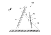
- FIG. 4 is a schematic diagram showing fixing contacts provided on the back surfaces of the first support member 101 and the second support member 103. It is a schematic diagram which shows the side surface of the stand 100A for electronic devices of a 1st state by 1st Embodiment. It is a schematic diagram which shows the side surface of the stand 100A for electronic devices of a 2nd state by 1st Embodiment. It is a schematic diagram which shows the side surface of the stand 100B for electronic devices by 2nd Embodiment.
- FIG. 4 is a schematic diagram showing how the solar cell module 104 rotates.
- An electronic device stand is an electronic device stand capable of holding an electronic device having a display surface and supplying electric power to the electronic device, and is a first holding for holding the electronic device.
- a first support member having a surface, a second support member having a second holding surface for holding a solar cell module that generates electric power, and an angle adjustment mechanism are provided.
- the angle adjustment mechanism is installed when the electronic device stand is arranged on the installation surface by the first support member and the second support member with the display surface and the light receiving surface of the solar cell module exposed to the outside.
- the first dihedral angle formed by the surface and the display surface and the second dihedral angle formed by the installation surface and the light receiving surface can be adjusted independently.
- Electronic devices include large liquid crystal display devices, small mobile electronic devices such as smartphones and tablet PCs, lighting devices, and internally illuminated signboards.
- the electronic device stand includes, for example, a desk stand, a standing signboard installed on the road, and a digital signage.
- the first support member and the second support member are typically rectangular.
- the electric power of the solar cell module is supplied to the electronic device by electrical connection between the first support member and the second support member.
- wireless power transmission technology since wireless power transmission technology has advanced in recent years, such technology can also be widely used.
- the angle ⁇ 1 formed by the display surface and the installation surface of the electronic device stand and the angle ⁇ 2 formed by the light receiving surface of the solar cell module and the installation surface can be independently adjusted. As a result, the visibility of the display surface is improved and the power generation amount of the solar cell module is also improved.
- FIG. 1A shows the appearance of the electronic device stand 100A as viewed from the front.
- FIG. 1B shows the appearance of the electronic device stand 100A as viewed from the back.
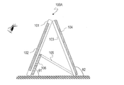
- FIG. 2 schematically shows a side surface of the electronic device stand 100A.
- the electronic device stand 100 ⁇ / b> A can hold the electronic device 102 having a display surface and supply power to the electronic device 102. As shown in FIG. 2, by placing the electronic device stand 100 ⁇ / b> A on a table or the like, the user operates the electronic device 102 while supplying power from the solar cell module 104 directly to the electronic device 102. You can watch the video displayed on the screen. Of course, the electric power from the solar cell module 104 may be temporarily stored in the storage battery.
- the electronic device stand 100A includes a first support member 101 having a first holding surface that holds the electronic device 102, and a solar cell module 104 that is electrically connected to the first support member 101 and generates electric power.
- a second support member 103 having a second holding surface to hold, and an angle adjusting mechanism capable of independently adjusting the angles ⁇ 1 and ⁇ 2 are provided.
- the angle ⁇ ⁇ b> 1 is an angle formed by the display surface (or the first support member 101) and the installation surface of the electronic device stand 100 ⁇ / b> A
- the angle ⁇ ⁇ b> 2 is installed with the light receiving surface of the solar cell module 104.
- the solar cell module 104 can be attached to the second holding surface of the second support member 103.
- the shapes of the first support member 101 and the second support member 103 are typically rectangular, but may be, for example, circular or elliptical.
- the shape includes all shapes in which the electronic device stand 100A can be placed upright on a table or the like. In the following, it is assumed that the shape is a rectangle as shown in the figure.
- solar cell module 104 Various solar cells can be used as the solar cell module 104.
- silicon-based solar cell modules such as crystalline silicon solar cell modules and amorphous silicon solar cell modules
- compound-based solar cell modules such as GaAs solar cell modules
- solar cell modules using fluorescent light collectors and dye-sensitized solar Organic solar cell modules such as battery modules
- dye-sensitized solar Organic solar cell modules such as battery modules
- the second support member 103 is provided with a power supply unit that supplies power from the solar cell module 104 to the electronic device 102.
- the power supply unit may have a control circuit that follows the optimum operating point of the solar cell module 104.
- the control circuit is generally called an MPPT (Maximum Power Point Tracking) circuit.
- the optimum operating point refers to an operating point at which the output power (product of current and voltage) of the solar cell module 104 is maximized.
- the MPPT circuit even when the illuminance or temperature changes, the solar cell module 104 can generate power at the maximum operating point under the circumstances, and the maximum power at that time can be obtained.
- a storage battery or the like can also be disposed on the second support member 103.
- the angle adjustment mechanism includes an adjustment member storage portion 106 and an adjustment member 105.
- the adjustment member 105 is in the form of a film and has conductivity.
- the first support member 101 and the second support member 103 are electrically connected by the adjustment member 105.
- the adjusting member 105 can be formed from, for example, copper or a copper alloy.
- the adjustment member 105 may be a member in which a conductor such as aluminum is covered with an insulating material such as polyvinyl chloride, polyethylene, and polypropylene.
- the adjustment member storage unit 106 includes a mechanism such as a cord reel and can wind up and store the adjustment member 105.
- the adjustment member storage unit 106 adjusts the length of the adjustment member 105. As a result, the angles ⁇ 1 and ⁇ 2 can be independently adjusted without being affected by geometric constraints.
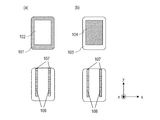
- FIG. 3A schematically shows the permanent magnet 107 and the soft magnetic body 108 on the back surface of the first support member 101 (the surface opposite to the surface on which the electronic device 102 is provided).
- FIG. 6 schematically shows the permanent magnet 107 and the soft magnetic body 108 on the back surface of the second support member 103 (the surface opposite to the surface on which the solar cell module 104 is provided).
- a fixing contact is provided on each of the back surfaces of the first support member 101 and the second support member 103. This will be specifically described below.
- a pair of stripe-shaped soft magnetic bodies 108 extending in the y-axis direction in the figure are provided.
- two or more soft magnetic materials may be provided in stripes at equal intervals, or may be provided in a mesh shape.
- the soft magnetic material is iron or nickel.
- a pair of permanent magnets 107 is provided adjacent to the pair of soft magnetic bodies 108 at one end of the first support member 101.
- the permanent magnet 107 may be provided in the whole part of the 1st supporting member which contact
- a pair of stripe-shaped soft magnetic bodies 108 extending in the y-axis direction are provided on the back surface of the second support member 103.
- a pair of permanent magnets 107 are provided adjacent to the pair of soft magnetic bodies 108 at one end of the second support member 103.
- each support member is not limited to the above-described arrangement, and the pair of permanent magnets 107 and the pair of soft magnetic bodies 108 are arranged at opposite positions. Also good. Again, they function as fixed contacts.
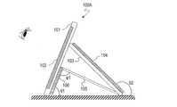
- FIG. 4A schematically illustrates a side surface of the electronic device stand 100A in the first state
- FIG. 4B schematically illustrates a side surface of the electronic device stand 100A in the second state
- the first state is a state in which the pair of permanent magnets 107 of the second support member 103 is in contact with the pair of soft magnetic bodies 108 of the first support member 101 at the position of the first contact
- the second state is a state in which the pair of permanent magnets 107 of the first support member 101 is in contact with the pair of soft magnetic bodies 108 of the second support member 103 at the position of the second contact.
- the ends of the first support member 101 and the second support member 103 may not contact each other. In other words, the end portion of the first support member 101 may not be connected to the end portion of the second support member 103.
- the electronic device stand 100A can be stably installed on a tabletop or the like.
- the angle ⁇ 1 between the first support member 101 (or the adjustment member storage unit 106) and the adjustment member 105 can be freely changed by the angle adjustment mechanism. Therefore, the angle ⁇ 1 can be uniquely determined so that each of the angles ⁇ 1 and ⁇ 2 becomes a desired angle.
- the angles ⁇ 1 and ⁇ 2 can be adjusted independently according to the position of the first or second contact and the length of the adjusting member 105, respectively. That is, the degree of freedom of angle adjustment is increased.
- the display surface can be adjusted to an easy-to-view angle, and the angle of the light receiving surface can be adjusted in the direction of external light irradiation, so that the amount of power generation can be improved.
- the first support member 101 and the second support member 103 can be firmly fixed at the position of the first or second contact, the electronic device stand 100A can be stably disposed. .
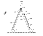
- the electronic device stand 100 ⁇ / b> B according to the present embodiment has the rotating shaft 110 so that the angle adjustment mechanism can adjust the incident angle of sunlight with respect to the light receiving surface of the solar cell module 104, and the electronic device according to the first embodiment. This is different from the stand 100A.
- description of common parts will be omitted, and description will be made focusing on differences.
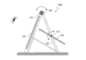
- FIG. 5 schematically shows a side surface of the electronic device stand 100B.
- FIG. 6 schematically shows the angle adjustment mechanism.
- the second support member 103 has an opening having a size that can accommodate the solar cell module 104.
- the shape of the opening is typically rectangular.
- a rotary shaft 110 that is substantially parallel to the x-axis direction is provided on the opening surface (xy plane in the drawing).
- the angle adjusting mechanism includes a connecting portion 109 and a rotating shaft 110.
- the connection unit 109 is realized by a hinge, for example.
- the connection portion 109 electrically connects one end of the first support member 101 and one end of the second support member 103. Further, the connecting portion 109 can adjust the angle ⁇ 3 formed by the first support member 101 and the second support member 103 to a predetermined angle.
- the rotary shaft 110 is provided in the opening, and both ends thereof are fixed to the outer frame 111.
- the rotating shaft 110 rotatably supports the solar cell module 104 so that the incident angle of sunlight with respect to the light receiving surface of the solar cell module 104 can be adjusted.
- the solar cell module 104 can be rotated around the rotating shaft 110 in the opening.
- the angle ⁇ 4 of the light receiving surface of the solar cell module 104 with respect to the second support member 103 can be adjusted to an arbitrary angle.
- a gap exists between the solar cell module 104 and the outer frame 111 in the opening in order to allow the solar cell module 104 to rotate smoothly. Therefore, the thermal radiation efficiency is increased by the gap. Further, for example, when the electronic device stand 100B is used as a standing signboard installed at a storefront or the like, stability is further improved by a structure in which the wind can escape from the gap even in a strong wind.
- the user can adjust the angle ⁇ 3 so that the display surface is easy to see. Thereafter, the user can optimally adjust the angle ⁇ 4 independently of the angle ⁇ 3 and direct the light-receiving surface in the direction of external light irradiation. That is, the angles ⁇ 1 and ⁇ 2 can be arbitrarily adjusted independently by the connecting portion 109 and the rotating shaft 110, respectively. Thereby, the display surface can be adjusted to an angle at which it is easy to see, and the power generation amount can be improved.
- the electronic device stand 100 ⁇ / b> B can be realized even by using another member that connects the first support member 101 and the second support member 103.
- the electronic device stand 100C according to this embodiment is different from the electronic device stand 100A according to the first embodiment in that the angle adjustment mechanism is a rail-type mechanism.
- the angle adjustment mechanism is a rail-type mechanism.
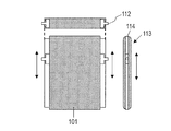
- FIG. 9A schematically shows the first support member 101 viewed from the front
- FIG. 9B schematically shows the second support member 103 viewed from the front.
- 9A and 9B also show respective side surfaces and cross sections.
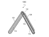
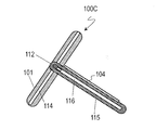
- FIG. 10A schematically shows a side surface of the electronic device stand 100C.
- the first support member 101 has a pair of side surfaces 113 parallel to each other.
- the side surface 113 is provided with a groove 114 in the direction in which it extends (the direction of the arrow in the figure).
- the pair of convex portions 112 is supported by the groove 114 so as to be able to translate along the groove 114 and is fixed at an arbitrary position.
- the second support member 103 has a pair of rail members 115 on a pair of side surfaces parallel to each other.
- the pair of rail members 115 have a pair of engaging grooves 116 that engage with the pair of convex portions 112 and slidably support the first support member 101.
- the first support member 101 is electrically connected to the second support member 103 by this engagement.
- the contact point between the pair of convex portions 112 and the pair of engagement grooves 116 is also an electrical contact.
- the embodiment according to the present invention is not limited to the above-described configuration.
- the pair of convex portions 112 may be provided on the second support member 103
- the pair of rail members 115 may be provided on the first support member 101. Good.
- the solar cell module 104 is shorter than the pair of rail members 115 by the thickness of the first support member 101 in the direction in which the pair of engagement grooves 116 extends. Therefore, the first support member 101 can be slid without the first support member 101 and the second support member 103 interfering with each other. Further, the electronic device stand 100C is placed on the table by combining the first support member 101 and the second support member 103 in a state where the pair of convex portions 112 and the pair of engagement grooves 116 are engaged with each other. be able to.
- FIG. 10B schematically shows a side surface of the electronic device stand 100C in the first state
- FIG. 10C schematically shows a side surface of the electronic device stand 100C in the second state.
- the first state is a state in which the pair of convex portions 112 are fixed at one end of the pair of grooves 114 and engaged with the pair of engagement grooves 116 near the center of the pair of engagement grooves 116.
- the second state is a state in which the pair of convex portions 112 are fixed near the center of the pair of grooves 114 and engaged at one end of the pair of engagement grooves 116.
- the angles ⁇ 1 and ⁇ 2 are independently determined according to the positions of the pair of protrusions 112 in the pair of grooves 114 and the positions of the pair of protrusions 112 in the pair of engagement grooves 116.
- the angles ⁇ 1 and ⁇ 2 can be arbitrarily adjusted independently.
- the display surface can be adjusted to an angle at which it is easy to see, and the power generation amount can be improved.
- the electronic device stand 100D is the first embodiment in that the angle adjustment mechanism includes a third support member 120 and a fourth support member 123 connected to each other via a hinge 122. This is different from the electronic device stand 100A.
- description of common parts will be omitted, and description will be made focusing on differences.
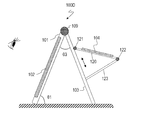
- FIG. 11 schematically shows a side surface of the electronic device stand 100D in a state where the fourth support member 123 is accommodated.
- FIG. 12 schematically shows the angle adjustment mechanism.
- FIG. 13 schematically illustrates a side surface of the electronic device stand 100D in a state where the fourth support member 123 is pulled out.
- the first support member 101 and the second support member 103 are electrically connected to each other through the connecting portion 109 as in the first embodiment.
- the connecting portion 109 With the connecting portion 109, the angle ⁇ 3 between the first support member 101 and the second support member 103 can be arbitrarily adjusted. Thereby, it can adjust to the angle which is easy to see a display surface.
- the second support member 103 is provided with an angle adjustment mechanism including a third support member 120, a hinge 122, and a fourth support member 123.
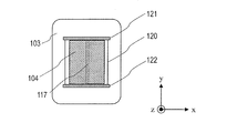
- the third support member 120 has an opening having a size that can accommodate the solar cell module 104.
- the opening is provided with a rotating shaft 117 parallel to the y-axis direction in the figure.
- the rotating shaft 117 rotatably supports the solar cell module so that the incident angle of sunlight with respect to the light receiving surface of the solar cell module 104 can be adjusted. Therefore, the solar cell module 104 can be rotated around the rotation shaft 117.
- One end of the third support member 120 is fixed to a support shaft 121 provided on the surface of the second support member 103. Therefore, the third support member 120 can be rotated around the support shaft 121.
- a hinge 122 is provided at the other end of the third support member 120.
- the fourth support member 123 is connected to the third support member 120 via a hinge 122.
- the fourth support member 123 can move between the storage position and the drawer position by the rotation of the third support member 120 around the support shaft 121 and the rotation around the hinge 122.
- the storage position is a position at which the third support member 120 completely folds over the fourth support member 123, and the pull-out position is a position pulled out from the storage position.
- the fourth support member 123 is fixed on the surface of the second support member 103 at an arbitrary position between the storage position and the drawer position. Thereby, the angle of the third support member 120 with respect to the second support member 103 can be changed.
- the angle ⁇ 1 can be adjusted by the connecting portion 109. Further, by sliding the fourth support member 123 between the storage position and the drawer position, the angle ⁇ 2 (not shown in FIG. 13) can be adjusted independently of the angle ⁇ 1.
- FIG. 14 shows how the solar cell module 104 rotates.
- the fourth support member 123 is pulled out from the storage position, a space is formed between the second support member 103, the third support member 120, and the fourth support member 123.
- the solar cell module 104 can be rotated around.
- the light receiving surface can be directed in the external light irradiation direction, so that the display surface is fixed at an easy-to-see position and efficiently generates power. Yes.
- the angles ⁇ 1 and ⁇ 2 can be arbitrarily adjusted independently.
- the display surface can be adjusted to an angle at which it is easy to see, and the power generation amount can be improved.
- An electronic device stand capable of holding an electronic device having a display surface and supplying power to the electronic device, A first support member having a first holding surface for holding the electronic device; A second support member having a second holding surface for holding the solar cell module for generating the electric power; With When the electronic device stand is disposed on an installation surface by the first support member and the second support member with the display surface and the light receiving surface of the solar cell module exposed to the outside, An electronic device stand capable of independently adjusting a first dihedral angle formed by an installation surface and the display surface and a second dihedral angle formed by the installation surface and the light receiving surface.
- the display surface can be adjusted to an angle at which it is easy to see, and the angle of the light receiving surface can be adjusted in the direction of external light irradiation, so that the amount of power generation can be improved.
- the first support member includes one of a first permanent magnet and a first soft magnetic body provided at one end thereof, and the first permanent magnet and the first soft magnet provided on the first back surface.
- the second support member includes one of a second permanent magnet and a second soft magnetic body provided at one end thereof, and the second support member opposite to the second holding surface.
- the other of the second permanent magnet and the second soft magnetic body provided on the second back surface of the second support member A position of a first contact point where the first permanent magnet and the second soft magnetic body are in contact with each other or a position of a second contact point where the second permanent magnet and the first soft magnetic body are in contact with each other; And according to the length of the adjustment member, the first dihedral angle and the second dihedral angle are respectively determined, One of the first and second support members supports the other with the first or second contact, and the angle formed by the first and second support members is fixed at a predetermined angle.
- the first support member and the second support member can be firmly fixed at the position of the first or second contact, so that the electronic device stand is stable. Can be arranged.
- the adjusting member has conductivity
- the electronic device stand according to item 2 or 3, wherein the first support member is electrically connected to the second support member via the adjustment member.
- the first support member and the second support member can be electrically connected.
- the second support member includes an opening having a size capable of accommodating the solar cell module, A connecting portion that electrically connects one end of the first support member and one end of the second support member, and adjusts an angle formed by the first and second support members to a predetermined angle; A rotation shaft provided in the opening and substantially parallel to the opening surface, the rotation shaft rotatably supporting the solar cell module so that an incident angle of sunlight with respect to a light receiving surface of the solar cell module can be adjusted;
- the heat radiation efficiency is increased by the gap.
- the stability is further improved by the structure in which the wind can escape from the gap even in a strong wind.
- the first support member and the second support member each have a pair of first side surfaces and second side surfaces that are parallel to each other, A pair of convex portions provided on one of the first side surface and the second side surface and movable in a direction in which the one side surface extends; and A pair of rail members that are provided on the other of the first side surface and the second side surface, engage with the pair of convex portions, and slidably support the one side;
- a connecting portion that electrically connects one end of the first support member and one end of the second support member, and adjusts an angle formed by the first and second support members to a predetermined angle;
- a support shaft provided on the surface of the second support member with the solar cell module;
- a third support member that is provided on the second support member and holds the solar cell module, one end of which is fixed to the support shaft and rotatable around the support shaft;
- a fourth support member having one end connected to the other end of the third support member via a hinge; Further comprising
- the fourth support member includes a storage position where the third support member is folded over the fourth support member by rotation of the third support member around the support shaft and rotation around the hinge, and the storage Item 1.
- the item can be moved between a drawing position drawn from a position and fixed on the surface of the second support member at an arbitrary position between the storage position and the drawing position. Stand for electronic equipment.
- the third support member includes an opening having a size capable of accommodating the solar cell module, and rotatably supports the solar cell module so that an incident angle of sunlight with respect to a light receiving surface of the solar cell module can be adjusted.
- Item 9 The electronic device stand according to Item 8, wherein the opening has a rotation axis substantially parallel to the opening surface.
- One end is connected to the first back surface of the first support member opposite to the first holding surface, and the other end is the second support member opposite to the second holding surface.
- a membrane member connected to the second back surface of The electronic device stand according to item 1, wherein an end portion of the first support member is not connected to an end portion of the second support member.
- the film-like member includes a conductive material and an insulating material that covers a part of the conductive material, Item 11.
- the electronic device stand according to Item 10, wherein the film-shaped member electrically connects the electronic device and the solar cell module.
- the first support member and the second support member can be electrically connected, and leakage or electric shock can be prevented by the insulating material.
- the present invention can be used for a stand for an electronic device provided with a solar cell module.
Landscapes
- Engineering & Computer Science (AREA)
- Physics & Mathematics (AREA)
- General Physics & Mathematics (AREA)
- Theoretical Computer Science (AREA)
- Multimedia (AREA)
- Signal Processing (AREA)
- Devices For Indicating Variable Information By Combining Individual Elements (AREA)
Abstract
L'invention concerne un support d'appareil électronique (100A), comprenant : un premier élément de support (101) doté d'une première surface de maintien pour maintenir un appareil électronique (102) ; et un second élément de support (103) doté d'une seconde surface de maintien pour maintenir un module de cellule solaire (104) qui génère de l'énergie. Lorsque le support d'appareil électronique est agencé sur une surface d'installation à l'aide du premier élément de support et du second élément de support, de telle sorte qu'une surface d'affichage et une surface de réception de lumière du module de cellule solaire sont exposées à l'extérieur, un premier angle dièdre θ1 formé entre la surface d'installation et la surface d'affichage et un second angle dièdre θ2 formé entre la surface d'installation et la surface de réception de lumière peuvent être réglés indépendamment l'un de l'autre.
Applications Claiming Priority (2)
| Application Number | Priority Date | Filing Date | Title |
|---|---|---|---|
| JP2015093919 | 2015-05-01 | ||
| JP2015-093919 | 2015-05-01 |
Publications (1)
| Publication Number | Publication Date |
|---|---|
| WO2016178383A1 true WO2016178383A1 (fr) | 2016-11-10 |
Family
ID=57217708
Family Applications (1)
| Application Number | Title | Priority Date | Filing Date |
|---|---|---|---|
| PCT/JP2016/062925 Ceased WO2016178383A1 (fr) | 2015-05-01 | 2016-04-25 | Support d'appareil électronique |
Country Status (1)
| Country | Link |
|---|---|
| WO (1) | WO2016178383A1 (fr) |
Cited By (2)
| Publication number | Priority date | Publication date | Assignee | Title |
|---|---|---|---|---|
| JP2020086156A (ja) * | 2018-11-27 | 2020-06-04 | セフテック株式会社 | 電源装置、撮影装置、および、撮影システム |
| JP2020179542A (ja) * | 2019-04-24 | 2020-11-05 | 日学株式会社 | ソーラーパネル付き情報記載・掲示板 |
Citations (9)
| Publication number | Priority date | Publication date | Assignee | Title |
|---|---|---|---|---|
| JPS5975280A (ja) * | 1982-10-22 | 1984-04-27 | キヤノン株式会社 | 電子機器 |
| JPS622081U (fr) * | 1985-06-18 | 1987-01-08 | ||
| JPS6443389U (fr) * | 1987-09-09 | 1989-03-15 | ||
| JP2009150456A (ja) * | 2007-12-19 | 2009-07-09 | Bank Of Tokyo-Mitsubishi Ufj Ltd | スタンド |
| JP3164803U (ja) * | 2010-10-05 | 2010-12-16 | 株式会社昌利 | 仮囲い板用掲示板 |
| JP2012104786A (ja) * | 2010-11-06 | 2012-05-31 | Yuushirou Kubo | 太陽光発電モジュールの設置構造 |
| JP2012109530A (ja) * | 2010-11-17 | 2012-06-07 | Samsung Electronics Co Ltd | 太陽電池部及びそれを有する表示装置 |
| JP2013023827A (ja) * | 2011-07-15 | 2013-02-04 | House Care Co Ltd | 太陽光発電装置の架台装置 |
| JP2013117602A (ja) * | 2011-12-02 | 2013-06-13 | Nippon Kayaku Co Ltd | 卓上表示機器 |
-
2016
- 2016-04-25 WO PCT/JP2016/062925 patent/WO2016178383A1/fr not_active Ceased
Patent Citations (9)
| Publication number | Priority date | Publication date | Assignee | Title |
|---|---|---|---|---|
| JPS5975280A (ja) * | 1982-10-22 | 1984-04-27 | キヤノン株式会社 | 電子機器 |
| JPS622081U (fr) * | 1985-06-18 | 1987-01-08 | ||
| JPS6443389U (fr) * | 1987-09-09 | 1989-03-15 | ||
| JP2009150456A (ja) * | 2007-12-19 | 2009-07-09 | Bank Of Tokyo-Mitsubishi Ufj Ltd | スタンド |
| JP3164803U (ja) * | 2010-10-05 | 2010-12-16 | 株式会社昌利 | 仮囲い板用掲示板 |
| JP2012104786A (ja) * | 2010-11-06 | 2012-05-31 | Yuushirou Kubo | 太陽光発電モジュールの設置構造 |
| JP2012109530A (ja) * | 2010-11-17 | 2012-06-07 | Samsung Electronics Co Ltd | 太陽電池部及びそれを有する表示装置 |
| JP2013023827A (ja) * | 2011-07-15 | 2013-02-04 | House Care Co Ltd | 太陽光発電装置の架台装置 |
| JP2013117602A (ja) * | 2011-12-02 | 2013-06-13 | Nippon Kayaku Co Ltd | 卓上表示機器 |
Cited By (2)
| Publication number | Priority date | Publication date | Assignee | Title |
|---|---|---|---|---|
| JP2020086156A (ja) * | 2018-11-27 | 2020-06-04 | セフテック株式会社 | 電源装置、撮影装置、および、撮影システム |
| JP2020179542A (ja) * | 2019-04-24 | 2020-11-05 | 日学株式会社 | ソーラーパネル付き情報記載・掲示板 |
Similar Documents
| Publication | Publication Date | Title |
|---|---|---|
| US8738101B1 (en) | Smartphone-tablet hybrid device | |
| KR102537850B1 (ko) | 카메라 어셈블리 및 단말 디바이스 | |
| JP3220625U (ja) | 折り畳み式ソーラーバッテリーパック | |
| CN102142207B (zh) | 具有形状变化特性的柔性电子产品及改变其形状的方法 | |
| US20130265644A1 (en) | Shielding apparatus and system for electronc device | |
| EP3311377B1 (fr) | Appareil d'affichage comportant un panneau d'affichage flexible | |
| ES2788641T3 (es) | Paquete de energía móvil y dispositivo terminal combinado | |
| US20140326840A1 (en) | Adjustable and Portable Mounting System for a Tablet Computing Device and Solar Based Charging System | |
| CN106027699B (zh) | 移动电子设备用外壳 | |
| KR102428743B1 (ko) | 휴대용 태양광 발전장치 | |
| CN212749556U (zh) | 一种双显折叠翻转智能手表 | |
| KR20160015796A (ko) | 휴대용 태양광 발전 장치 | |
| US20160278493A1 (en) | Electronic apparatus case | |
| CN116034642A (zh) | 串联连接的光电转换元件 | |
| WO2020030449A1 (fr) | Drapeau a dispositif integre | |
| US20090145473A1 (en) | Solar panel curtain | |
| Nickel et al. | Radiation hardness and self-healing of perovskite solar cells under proton irradiation (Conference Presentation) | |
| KR102534480B1 (ko) | 전자기기 지지장치 및 디스플레이 디바이스 | |
| CN110994767B (zh) | 一种太阳能移动设备充电装置 | |
| Schmid et al. | Concentrating light in Cu (In, Ga) Se 2 solar cells | |
| WO2021185349A1 (fr) | Dispositif électronique | |
| KR102810221B1 (ko) | 태양전지패널이 내장된 휴대용 단말기 충전장치 | |
| US20260141826A1 (en) | Foldable outdoor digital signage display | |
| CN223929660U (zh) | 一种多功能手提包 | |
| CN208316345U (zh) | 一种无线充电器 |
Legal Events
| Date | Code | Title | Description |
|---|---|---|---|
| 121 | Ep: the epo has been informed by wipo that ep was designated in this application |
Ref document number: 16789519 Country of ref document: EP Kind code of ref document: A1 |
|
| NENP | Non-entry into the national phase |
Ref country code: DE |
|
| 122 | Ep: pct application non-entry in european phase |
Ref document number: 16789519 Country of ref document: EP Kind code of ref document: A1 |
|
| NENP | Non-entry into the national phase |
Ref country code: JP |