WO2016178391A1 - 長尺状のガスバリア性フィルムおよびその製造方法、ならびに短尺状のガスバリア性フィルムおよびその製造方法 - Google Patents
長尺状のガスバリア性フィルムおよびその製造方法、ならびに短尺状のガスバリア性フィルムおよびその製造方法 Download PDFInfo
- Publication number
- WO2016178391A1 WO2016178391A1 PCT/JP2016/063058 JP2016063058W WO2016178391A1 WO 2016178391 A1 WO2016178391 A1 WO 2016178391A1 JP 2016063058 W JP2016063058 W JP 2016063058W WO 2016178391 A1 WO2016178391 A1 WO 2016178391A1
- Authority
- WO
- WIPO (PCT)
- Prior art keywords
- gas barrier
- film
- barrier film
- barrier layer
- cleaning
- Prior art date
- Legal status (The legal status is an assumption and is not a legal conclusion. Google has not performed a legal analysis and makes no representation as to the accuracy of the status listed.)
- Ceased
Links
Images


Classifications
-
- B—PERFORMING OPERATIONS; TRANSPORTING
- B32—LAYERED PRODUCTS
- B32B—LAYERED PRODUCTS, i.e. PRODUCTS BUILT-UP OF STRATA OF FLAT OR NON-FLAT, e.g. CELLULAR OR HONEYCOMB, FORM
- B32B9/00—Layered products comprising a layer of a particular substance not covered by groups B32B11/00 - B32B29/00
-
- B—PERFORMING OPERATIONS; TRANSPORTING
- B32—LAYERED PRODUCTS
- B32B—LAYERED PRODUCTS, i.e. PRODUCTS BUILT-UP OF STRATA OF FLAT OR NON-FLAT, e.g. CELLULAR OR HONEYCOMB, FORM
- B32B15/00—Layered products comprising a layer of metal
- B32B15/04—Layered products comprising a layer of metal comprising metal as the main or only constituent of a layer, which is next to another layer of the same or of a different material
- B32B15/08—Layered products comprising a layer of metal comprising metal as the main or only constituent of a layer, which is next to another layer of the same or of a different material of synthetic resin
-
- C—CHEMISTRY; METALLURGY
- C23—COATING METALLIC MATERIAL; COATING MATERIAL WITH METALLIC MATERIAL; CHEMICAL SURFACE TREATMENT; DIFFUSION TREATMENT OF METALLIC MATERIAL; COATING BY VACUUM EVAPORATION, BY SPUTTERING, BY ION IMPLANTATION OR BY CHEMICAL VAPOUR DEPOSITION, IN GENERAL; INHIBITING CORROSION OF METALLIC MATERIAL OR INCRUSTATION IN GENERAL
- C23C—COATING METALLIC MATERIAL; COATING MATERIAL WITH METALLIC MATERIAL; SURFACE TREATMENT OF METALLIC MATERIAL BY DIFFUSION INTO THE SURFACE, BY CHEMICAL CONVERSION OR SUBSTITUTION; COATING BY VACUUM EVAPORATION, BY SPUTTERING, BY ION IMPLANTATION OR BY CHEMICAL VAPOUR DEPOSITION, IN GENERAL
- C23C14/00—Coating by vacuum evaporation, by sputtering or by ion implantation of the coating forming material
- C23C14/06—Coating by vacuum evaporation, by sputtering or by ion implantation of the coating forming material characterised by the coating material
- C23C14/08—Oxides
Definitions
- the present invention relates to a long gas barrier film and a manufacturing method thereof, and a short gas barrier film and a manufacturing method thereof.
- Gas barrier films are used as substrate films and sealing films in flexible electronic devices, particularly flexible organic EL devices. High barrier properties are required for gas barrier films used in these.
- a gas barrier film is manufactured by forming an inorganic barrier layer on a base film by a vapor deposition method such as vapor deposition, sputtering, or CVD.
- a manufacturing method for forming a gas barrier layer by applying energy to a precursor layer formed by applying a solution on a substrate has been studied.
- studies using a polysilazane compound as a precursor have been widely conducted, and studies are being conducted as a technique for achieving both high productivity and barrier properties by coating.
- the modification of the polysilazane layer using excimer light having a wavelength of 172 nm has attracted attention.
- International Publication No. 2011/122547 (corresponding to US Patent Application Publication No. 2013/047889) has a gas barrier layer obtained by implanting hydrocarbon compound ions into a layer containing a polysilazane compound.
- An elongated shaped body is disclosed.
- an object of the present invention is to provide a long gas barrier film excellent in durability in a high temperature and high humidity environment.
- Another object of the present invention is to provide a short gas barrier film excellent in durability in a high temperature and high humidity environment.
- the present inventor has conducted intensive research to solve the above problems.
- the carbon when the atomic composition ratio of silicon to metal is 1: 1.
- the composition ratio of silicon, metal, nitrogen, oxygen, and carbon is 100 atm%, and it is found that the above problem is solved by a long gas barrier film that is less than 2.0 atm%.
- the invention has been completed.
- the present invention provides a gas barrier layer containing silicon and nitrogen provided on a long resin substrate, and is provided in contact with the gas barrier layer, and includes V, Nb, Ta, Ti, Zr, Hf, Mg And a metal oxide layer containing an oxide of at least one metal selected from the group consisting of Y, Y, and Al, and a gas barrier film having a long shape, the thickness direction of the gas barrier film
- the composition ratio of carbon when the atomic composition ratio of silicon to metal is 1: 1 is silicon, metal, nitrogen. , Oxygen, and carbon, the total amount of which is 100 atm%, and is a long gas barrier film that is less than 2.0 atm%.
- FIG. 10 is an apparatus chamber
- 12 is a Xe excimer lamp
- 13 is an excimer lamp holder that also serves as an external electrode
- 14 is a sample stage
- 15 is a base material sample on which a polysilazane coating film is formed
- 16 is a light shielding plate.
- FIG. 1 shows an example of the apparatus used when manufacturing a elongate gas barrier film
- 1 is a film laminated body
- 20 is a gas barrier film manufacturing apparatus
- 21 is a resin base material
- 22a and 22c are feed rollers
- 22b is a take-up roller
- 23a, 23b, 23c, 23d, 23e, 23f, 23g and 23h are transport rollers
- 23i and 23j are nip rolls
- 23k is a touch roller 24 is a coating means
- 25 is a drying means
- 27 is a protective film
- 28 is a modification treatment means.
- the “long shape” means a film having a length of at least 5 times or more with respect to the width direction of the film, preferably having a length of 10 times or more, specifically It has a length that can be stored in a roll and stored or transported.
- the present invention provides a gas barrier layer containing silicon and nitrogen provided on a long resin substrate, and is provided in contact with the gas barrier layer, and includes V, Nb, Ta, Ti, Zr, Hf, Mg, Y And a metal oxide layer containing an oxide of at least one metal selected from the group consisting of Al, and a long gas barrier film having an X in the thickness direction of the gas barrier film.
- the composition ratio of carbon when the atomic composition ratio of silicon to metal is 1: 1 is A long gas barrier film having a total amount of silicon, metal, nitrogen, oxygen and carbon of 100 atm% and less than 2.0 atm%.
- the long gas barrier film of the present invention having such a configuration is excellent in durability in a high temperature and high humidity environment.
- the present inventor has intensively studied to solve the problem that the durability in a high temperature and high humidity environment is lowered in the conventional gas barrier film.
- the inventors found that the amount of carbon in the vicinity of the surface of the gas barrier layer is related to the durability of the gas barrier film, and focused on this point.
- a protective film is laminated on the gas barrier layer and wound up for the purpose of protecting the gas barrier layer.
- the protective film is usually provided with an adhesive layer, but it was estimated that the surface of the gas barrier layer was contaminated by substances contained in the adhesive layer, and the durability in a high-temperature and high-humidity environment was reduced.
- the present inventor has obtained the atomic composition distribution obtained when the composition analysis by XPS is performed in the thickness direction of the gas barrier film in the gas barrier film having the gas barrier layer containing silicon and nitrogen and the metal oxide layer. From the profile, it was found that durability is improved by reducing the carbon composition ratio when the atomic composition ratio of silicon and metal is 1: 1, and the present invention has been completed.
- the point where the atomic composition ratio of silicon to metal is 1: 1 is in the vicinity of the interface between the gas barrier layer and the metal oxide layer. By reducing the carbon composition ratio at this point, the contamination of the gas barrier layer surface is reduced. It is considered that the durability of the long gas barrier film is improved.
- the gas barrier layer according to the present invention contains silicon and nitrogen. Such a gas barrier layer is preferably formed by applying energy to a coating film obtained by applying and drying a coating liquid containing polysilazane.
- the gas barrier layer develops gas barrier properties when energy is applied. Further, unlike the case where the film is formed by the vapor deposition method, foreign substances such as particles are not mixed at the time of film formation, so that the gas barrier layer has very few defects.
- the gas barrier layer may be a single layer or a laminated structure of two or more layers.
- Polysilazane is a polymer having a silicon-nitrogen bond, such as SiO 2 , Si 3 N 4 having a bond such as Si—N, Si—H, or N—H, and ceramics such as both intermediate solid solutions SiO x N y. It is a precursor inorganic polymer.
- the polysilazane preferably has the following structure.
- R 1 , R 2 and R 3 are each independently a hydrogen atom, a substituted or unsubstituted alkyl group, aryl group, vinyl group or (trialkoxysilyl) alkyl group. . At this time, R 1 , R 2 and R 3 may be the same or different.
- n is an integer
- the polysilazane having the structure represented by the general formula (I) is determined to have a number average molecular weight of 150 to 150,000 g / mol. Is preferred.
- one of preferred embodiments is perhydropolysilazane in which all of R 1 , R 2 and R 3 are hydrogen atoms.
- polysilazane has a structure represented by the following general formula (II).
- R 1 ′ , R 2 ′ , R 3 ′ , R 4 ′ , R 5 ′ and R 6 ′ are each independently a hydrogen atom, a substituted or unsubstituted alkyl group, An aryl group, a vinyl group or a (trialkoxysilyl) alkyl group.
- R 1 ′ , R 2 ′ , R 3 ′ , R 4 ′ , R 5 ′ and R 6 ′ may be the same or different.
- n ′ and p are integers, and the polysilazane having the structure represented by the general formula (II) is determined to have a number average molecular weight of 150 to 150,000 g / mol. It is preferred that Note that n ′ and p may be the same or different.
- R 1 ′ , R 3 ′ and R 6 ′ each represent a hydrogen atom, and R 2 ′ , R 4 ′ and R 5 ′ each represent a methyl group;
- R 1 ' , R 3' and R 6 ' each represents a hydrogen atom, R 2' , R 4 ' each represents a methyl group, and R 5' represents a vinyl group;
- R 1 ' , R 3' , R 4 A compound in which ' and R 6' each represent a hydrogen atom and R 2 ' and R 5' each represents a methyl group is preferred.
- polysilazane has a structure represented by the following general formula (III).
- R 1 ′′ , R 2 ′′ , R 3 ′′ , R 4 ′′ , R 5 ′′ , R 6 ′′ , R 7 ′′ , R 8 ′′ and R 9 ′′ are each independently A hydrogen atom, a substituted or unsubstituted alkyl group, aryl group, vinyl group or (trialkoxysilyl) alkyl group, wherein R 1 ′′ , R 2 ′′ , R 3 ′′ , R 4 ′′ , R 5 ′′ , R 6 ′′ , R 7 ′′ , R 8 ′′ and R 9 ′′ may be the same or different.
- n ′′, p ′′ and q are integers, and the polysilazane having the structure represented by the general formula (III) has a number average molecular weight of 150 to 150,000 g / mol. It is preferable to be determined as follows. Note that n ′′, p ′′, and q may be the same or different.
- R 1 ′′ , R 3 ′′ and R 6 ′′ each represent a hydrogen atom
- R 2 ′′ , R 4 ′′ , R 5 ′′ and R 8 ′′ each represent a methyl group.
- R 9 ′′ represents a (triethoxysilyl) propyl group
- R 7 ′′ represents an alkyl group or a hydrogen atom.
- the organopolysilazane in which a part of the hydrogen atom part bonded to Si is substituted with an alkyl group or the like has improved adhesion to the base resin substrate by having an alkyl group such as a methyl group, and
- the ceramic film made of hard and brittle polysilazane can be toughened, and there is an advantage that generation of cracks can be suppressed even when the (average) film thickness is increased. For this reason, these perhydropolysilazane and organopolysilazane may be appropriately selected according to the application, and may be used in combination.
- Perhydropolysilazane is presumed to have a linear structure and a ring structure centered on 6- and 8-membered rings.
- the number average molecular weight (Mn) is about 600 to 2000 (polystyrene conversion), and there are liquid or solid substances, and the state varies depending on the molecular weight.
- Polysilazane is commercially available in a solution state dissolved in an organic solvent, and the commercially available product can be used as it is as a coating solution for forming a gas barrier layer.
- Examples of commercially available polysilazane solutions include NN120-10, NN120-20, NAX120-20, NN110, NN310, NN320, NL110A, NL120A, NL120-20, NL150A, NP110, NP140, and SP140 manufactured by AZ Electronic Materials Co., Ltd. Is mentioned. These polysilazane solutions can be used alone or in combination of two or more.
- polysilazane examples include, but are not limited to, for example, a silicon alkoxide-added polysilazane obtained by reacting the polysilazane with a silicon alkoxide (Japanese Patent Laid-Open No. 5-23827), and a glycidol reaction.
- a silicon alkoxide-added polysilazane obtained by reacting the polysilazane with a silicon alkoxide
- glycidol-added polysilazane Japanese Patent Laid-Open No. 6-122852
- alcohol-added polysilazane obtained by reacting alcohol
- metal carboxylate obtained by reacting metal carboxylate Addition polysilazane (JP-A-6-299118), acetylacetonate complex-added polysilazane obtained by reacting a metal-containing acetylacetonate complex (JP-A-6-306329), metal obtained by adding metal fine particles Fine particle added policy Zhang such (JP-A-7-196986), and a polysilazane ceramic at low temperatures.
- the solvent for preparing the coating liquid for forming the gas barrier layer is not particularly limited as long as it can dissolve polysilazane, but water and reactive groups (for example, hydroxyl group or amine group) that easily react with polysilazane. Etc.), an organic solvent inert to polysilazane is preferred, and an aprotic organic solvent is more preferred.
- the solvent is an aprotic solvent; for example, carbon such as aliphatic hydrocarbons, alicyclic hydrocarbons, aromatic hydrocarbons such as pentane, hexane, cyclohexane, toluene, xylene, solvesso, terpenes, etc.
- Hydrogen solvents Halogen hydrocarbon solvents such as methylene chloride and trichloroethane; Esters such as ethyl acetate and butyl acetate; Ketones such as acetone and methyl ethyl ketone; Aliphatic ethers such as dibutyl ether, dioxane and tetrahydrofuran; Alicyclic ethers and the like Ethers: Examples include tetrahydrofuran, dibutyl ether, mono- and polyalkylene glycol dialkyl ethers (diglymes), and the like.
- the solvent is selected according to purposes such as the solubility of polysilazane and the evaporation rate of the solvent, and may be used alone or in the form of a mixture of two or more.
- the concentration of polysilazane in the gas barrier layer forming coating solution is not particularly limited, and varies depending on the film thickness of the layer and the pot life of the coating solution, but is preferably 1 to 80% by mass, more preferably 5 to 50% by mass, The amount is preferably 10 to 40% by mass.
- the gas barrier layer forming coating solution preferably contains a catalyst in order to promote reforming.
- a basic catalyst is preferable, and in particular, N, N-diethylethanolamine, N, N-dimethylethanolamine, triethanolamine, triethylamine, 3-morpholinopropylamine, N, N, Amine catalysts such as N ′, N′-tetramethyl-1,3-diaminopropane, N, N, N ′, N′-tetramethyl-1,6-diaminohexane, Pt compounds such as Pt acetylacetonate, propion Examples thereof include metal catalysts such as Pd compounds such as acid Pd, Rh compounds such as Rh acetylacetonate, and N-heterocyclic compounds.
- the concentration of the catalyst added at this time is preferably in the range of 0.1 to 10% by mass, more preferably 0.5 to 7% by mass, based on the silicon compound. By setting the amount of the catalyst to be in this range, it is possible to avoid excessive silanol formation due to rapid progress of the reaction, reduction in film density, increase in film defects, and the like.
- the following additives may be added to the gas barrier layer forming coating solution as necessary.
- cellulose ethers, cellulose esters for example, ethyl cellulose, nitrocellulose, cellulose acetate, cellulose acetobutyrate, etc.
- natural resins for example, rubber, rosin resin, etc., synthetic resins
- Aminoplasts especially urea resins, melamine formaldehyde resins, alkyd resins, acrylic resins, polyester resins or modified polyester resins, epoxy resins, polyisocyanates or blocked polyisocyanates, or polysiloxanes.
- Method of applying gas barrier layer forming coating solution As a method for applying the gas barrier layer forming coating solution, a conventionally known appropriate wet coating method may be employed. Specific examples include spin coating method, roll coating method, flow coating method, ink jet method, spray coating method, printing method, dip coating method, casting film forming method, bar coating method, die coating method, gravure printing method and the like. It is done.
- the coating thickness can be appropriately set according to the preferred thickness and purpose.
- the thickness of the coating solution (coating film) after drying is preferably 40 to 1000 nm, more preferably 100 to 300 nm. It is.
- the coating film After applying the coating solution, the coating film is dried. By drying the coating film, the organic solvent contained in the coating film can be removed. At this time, all of the organic solvent contained in the coating film may be dried or may be partially left. Even when a part of the organic solvent is left, a suitable gas barrier layer can be obtained. The remaining solvent can be removed later.
- the drying temperature of the coating film varies depending on the resin substrate to be applied, but is preferably 50 to 200 ° C.
- the drying temperature may be set to 150 ° C. or less in consideration of deformation of the resin substrate due to heat. preferable.
- the temperature can be set by using a hot plate, oven, furnace or the like.
- the drying time is preferably set to a short time. For example, when the drying temperature is 150 ° C., the drying time is preferably set within 30 minutes.
- the drying atmosphere may be any condition such as an air atmosphere, a nitrogen atmosphere, an argon atmosphere, a vacuum atmosphere, or a reduced pressure atmosphere with a controlled oxygen concentration.
- the conversion reaction of polysilazane to silicon oxide or silicon oxynitride can be applied by appropriately selecting a known method.
- Specific examples of the modification treatment include plasma treatment, ultraviolet irradiation treatment, and heat treatment.
- a plasma treatment capable of a conversion reaction at a lower temperature or a conversion reaction by ultraviolet irradiation treatment is preferable.
- plasma treatment and ultraviolet irradiation treatment which are preferable modification treatment methods, will be described.
- a known method can be used for the plasma treatment that can be used as the reforming treatment, and an atmospheric pressure plasma treatment or the like can be preferably used.
- the atmospheric pressure plasma CVD method which performs plasma CVD processing near atmospheric pressure, does not need to be reduced in pressure and is more productive than the plasma CVD method under vacuum.
- the film speed is high, and further, under a high pressure condition under atmospheric pressure as compared with the conditions of a normal CVD method, the gas mean free process is very short, so that a very homogeneous film can be obtained.
- nitrogen gas or a gas containing Group 18 atoms of the long-period periodic table specifically helium, neon, argon, krypton, xenon, radon, or the like is used.
- nitrogen, helium, and argon are preferably used, and nitrogen is particularly preferable because of low cost.
- UV irradiation treatment As one of the modification treatment methods, treatment by ultraviolet irradiation is preferable. Ozone and active oxygen atoms generated by ultraviolet rays (synonymous with ultraviolet light) have high oxidation ability, and can form silicon oxide films or silicon oxynitride films with high density and insulation at low temperatures It is.
- the base material is heated, and O 2 and H 2 O contributing to ceramicization (silica conversion), an ultraviolet absorber, and polysilazane itself are excited and activated.
- the conversion to ceramics is promoted, and the resulting gas barrier layer becomes denser. Irradiation with ultraviolet rays is effective at any time after the formation of the coating film.
- any commonly used ultraviolet ray generator can be used.
- the ultraviolet ray referred to in the present invention generally refers to an electromagnetic wave having a wavelength of 10 to 400 nm, but in the case of an ultraviolet irradiation treatment other than the vacuum ultraviolet ray (10 to 200 nm) treatment described later, it is preferably 210 to 375 nm. Use ultraviolet light.
- the irradiation intensity and the irradiation time are set within a range in which the substrate carrying the irradiated gas barrier layer is not damaged.
- a 2 kW (80 W / cm ⁇ 25 cm) lamp is used, and the strength of the base material surface is usually 20 to 300 mW / cm 2 , preferably 50 to 200 mW /
- the distance between the substrate and the ultraviolet irradiation lamp is set so as to be cm 2, and irradiation can be performed for 0.1 seconds to 10 minutes.
- ultraviolet ray generating means examples include metal halide lamps, high pressure mercury lamps, low pressure mercury lamps, xenon arc lamps, carbon arc lamps, and excimer lamps (single wavelengths of 172 nm, 222 nm, and 308 nm, for example, USHIO INC. Manufactured by M.D. Com Co., Ltd.), UV light laser, and the like, but are not particularly limited.
- metal halide lamps high pressure mercury lamps, low pressure mercury lamps, xenon arc lamps, carbon arc lamps, and excimer lamps (single wavelengths of 172 nm, 222 nm, and 308 nm, for example, USHIO INC. Manufactured by M.D. Com Co., Ltd.), UV light laser, and the like, but are not particularly limited.
- UV irradiation can be applied to both batch processing and continuous processing, and can be appropriately selected depending on the shape of the substrate used.
- a laminate having a gas barrier layer on the surface can be processed in an ultraviolet baking furnace equipped with an ultraviolet source as described above.
- the ultraviolet baking furnace itself is generally known.
- an ultraviolet baking furnace manufactured by I-Graphics Co., Ltd. can be used.
- the laminated body having the gas barrier layer on the surface is a long film, it is converted into ceramics by continuously irradiating ultraviolet rays in the drying zone equipped with the ultraviolet ray generation source as described above while being conveyed. can do.
- the time required for ultraviolet irradiation is generally 0.1 seconds to 10 minutes, preferably 0.5 seconds to 3 minutes, although it depends on the composition and concentration of the substrate and gas barrier layer used.
- the most preferable modification treatment method is treatment by vacuum ultraviolet irradiation (excimer irradiation treatment).
- the treatment by the vacuum ultraviolet irradiation uses light energy of 100 to 200 nm, preferably light energy of a wavelength of 100 to 180 nm, which is larger than the interatomic bonding force in the polysilazane compound, and bonds atoms with only photons called photon processes.
- This is a method of forming a silicon oxide film at a relatively low temperature (about 200 ° C. or lower) by causing an oxidation reaction with active oxygen or ozone to proceed while cutting directly by action.
- the vacuum ultraviolet ray source in the present invention may be any source that generates light having a wavelength of 100 to 180 nm, but is preferably an excimer radiator (for example, Xe excimer lamp) having a maximum emission at about 172 nm, and an emission line at about 185 nm.
- Excimer radiator for example, Xe excimer lamp
- Low pressure mercury vapor lamps with medium pressure and medium and high pressure mercury vapor lamps with wavelength components of 230 nm or less and excimer lamps with maximum emission at about 222 nm.
- the Xe excimer lamp emits ultraviolet light having a short wavelength of 172 nm at a single wavelength, and thus has excellent luminous efficiency. Since this light has a large oxygen absorption coefficient, it can generate radical oxygen atom species and ozone at a high concentration with a very small amount of oxygen.
- the energy of light having a short wavelength of 172 nm has a high ability to dissociate organic bonds.
- the coating film can be modified in a short time by the high energy possessed by the active oxygen, ozone and ultraviolet radiation.
- ⁇ Excimer lamps have high light generation efficiency and can be lit with low power.
- light having a long wavelength that causes a temperature increase due to light is not emitted, and energy is irradiated in the ultraviolet region, that is, in a short wavelength, so that the increase in the surface temperature of the target object is suppressed.
- it is suitable for flexible film materials such as PET that are easily affected by heat.
- Oxygen is required for the reaction at the time of vacuum ultraviolet irradiation, but since vacuum ultraviolet rays are absorbed by oxygen, the efficiency in the ultraviolet irradiation process tends to decrease.
- it is preferably performed in a state where the water vapor concentration is low. That is, the oxygen concentration at the time of irradiation with vacuum ultraviolet rays is preferably 10 to 20,000 volume ppm (0.001 to 2 volume%), and preferably 50 to 10,000 volume ppm (0.005 to 1 volume%). More preferably.
- the water vapor concentration during the conversion process is preferably in the range of 1,000 to 4,000 volume ppm.
- the gas satisfying the irradiation atmosphere used at the time of irradiation with vacuum ultraviolet rays is preferably a dry inert gas, and particularly preferably dry nitrogen gas from the viewpoint of cost.
- the oxygen concentration can be adjusted by measuring the flow rate of oxygen gas and inert gas introduced into the irradiation chamber and changing the flow rate ratio.
- the illuminance of the vacuum ultraviolet ray on the coating surface received by the coating film is preferably 1 mW / cm 2 to 10 W / cm 2 , more preferably 30 mW / cm 2 to 200 mW / cm 2. and further preferably 50mW / cm 2 ⁇ 160mW / cm 2. If it is 1 mW / cm 2 or more, the reforming efficiency is improved, and if it is 10 W / cm 2 or less, ablation that can occur in the coating film and damage to the resin substrate can be reduced.
- the amount of irradiation energy (irradiation amount) of vacuum ultraviolet rays on the coating surface is preferably 100 mJ / cm 2 to 50 J / cm 2 , more preferably 200 mJ / cm 2 to 20 J / cm 2 , and 500 mJ / cm 2. More preferably, it is 2 to 10 J / cm 2 . If it is 100 mJ / cm 2 or more, the modification is sufficient, and if it is 50 J / cm 2 or less, generation of cracks due to excessive modification and thermal deformation of the resin substrate can be suppressed.
- the vacuum ultraviolet ray used may be generated by plasma formed of a gas containing at least one of CO, CO 2 and CH 4 .
- the gas containing at least one of CO, CO 2 and CH 4 hereinafter also referred to as carbon-containing gas
- the carbon-containing gas may be used alone, but carbon containing rare gas or H 2 as the main gas. It is preferable to add a small amount of the contained gas. Examples of plasma generation methods include capacitively coupled plasma.
- the thickness of the gas barrier layer (the total thickness in the case of a laminated structure of two or more layers) is preferably 10 to 1000 nm, and more preferably 50 to 600 nm. If it is this range, the balance of gas barrier property and durability becomes favorable and is preferable.
- the thickness of the gas barrier layer can be measured by TEM observation.
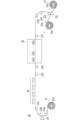
- the gas barrier film of the present invention is a metal containing an oxide of at least one metal selected from the group consisting of Nb, Ta, V, Zr, Ti, Hf, Mg, Y, and Al on the gas barrier layer. It has an oxide layer. These metals have a lower redox potential than Si and are more easily oxidized than silicon. Therefore, oxidation of the gas barrier layer can be suppressed, and durability in a high temperature and high humidity environment can be improved.
- Nb, Ta, and V which are Group 5 elements can be preferably used because they have a higher effect of suppressing oxidation of the gas barrier layer. Furthermore, from the viewpoint of optical properties, Nb and Ta from which a layer with good transparency can be obtained are more preferable, and Nb is more preferable.
- the content of the metal oxide in the metal oxide layer is not particularly limited as long as the effect of the present invention is achieved, but is preferably 50% by mass or more, and 80% by mass or more with respect to the total mass of the metal oxide layer. More preferably, it is more preferably 95% by mass or more, particularly preferably 98% by mass or more, and 100% by mass (that is, the metal oxide layer is made of a metal oxide). Most preferred.
- Examples of compounds that can be contained in the metal oxide layer other than the metal oxide include nitrides, nitride oxides, and carbonates of the above metals.
- the formation method of the metal oxide layer is preferably a vapor deposition method from the viewpoint of ease.
- the vapor deposition method is not particularly limited, and examples thereof include physical vapor deposition (PVD) methods such as sputtering, vapor deposition, and ion plating, plasma CVD (chemical vapor deposition), and ALD (Atomic Layer Deposition). ) And the like. Among them, it is preferable to form by sputtering since film formation is possible without damaging the lower layer and high productivity is obtained.
- bipolar sputtering, magnetron sputtering, dual magnetron (DMS) sputtering using an intermediate frequency region, ion beam sputtering, ECR sputtering, or the like can be used alone or in combination of two or more.
- the target application method is appropriately selected according to the target type, and either DC (direct current) sputtering or RF (high frequency) sputtering may be used.
- RF high frequency
- a reactive sputtering method using a transition mode that is intermediate between the metal mode and the oxide mode can also be used.
- a metal oxide film By controlling the sputtering phenomenon so as to be in the transition region, a metal oxide film can be formed at a high film formation speed, which is preferable.
- a thin film of an oxide containing the above metal can be formed by using the above metal for the target and further introducing oxygen into the process gas.
- the metal oxide target In the case of forming a film by RF (high frequency) sputtering, the metal oxide target can be used.
- the inert gas used for the process gas He, Ne, Ar, Kr, Xe, or the like can be used, and Ar is preferably used.
- a transition metal compound thin film such as a metal oxide, nitride, nitride oxide, or carbonate can be formed.
- film formation conditions in the sputtering method include applied power, discharge current, discharge voltage, time, and the like, which can be appropriately selected according to the sputtering apparatus, film material, film thickness, and the like.
- a sputtering method using a metal oxide as a target is preferable because it has a higher film formation rate and higher productivity.
- the metal oxide layer may be a single layer or a laminated structure of two or more layers.
- the metal contained in each metal oxide layer may be the same or different.
- the thickness of the metal oxide layer (the total thickness in the case of a laminated structure of two or more layers) is not particularly limited, but is preferably 1 to 500 nm, preferably 3 to 300 nm, and preferably 5 to 200 nm. It is more preferable that If it is this range, the oxidation of a gas barrier layer can be suppressed more efficiently.
- long resin base material examples include polyester resins, methacrylic resins, and methacrylic acid-maleic acid.
- Copolymer polystyrene resin, transparent fluororesin, polyimide resin, fluorinated polyimide resin, polyamide resin, polyamideimide resin, polyetherimide resin, cellulose acylate resin, polyurethane resin, polyetheretherketone resin, polycarbonate resin, alicyclic Thermoplastic resins such as polyolefin resin, polyarylate resin, polyethersulfone resin, polysulfone resin, cycloolefin copolymer, fluorene ring-modified polycarbonate resin, alicyclic ring-modified polycarbonate resin, fluorene ring-modified polyester resin, acryloyl compound A substrate comprising the like. These resin substrates can be used alone or in combination of two or more.
- the resin base material is preferably made of a heat-resistant material. Specifically, a resin base material having a linear expansion coefficient of 15 ppm / K or more and 100 ppm / K or less and a glass transition temperature (Tg) of 100 ° C. or more and 300 ° C. or less is used.
- Tg glass transition temperature
- the resin base material satisfies the necessary conditions as a laminated film for electronic parts and displays. That is, when the gas barrier film according to the present invention is used for these applications, the gas barrier film may be exposed to a process at 150 ° C. or higher.
- the substrate dimensions are not stable when the gas barrier film is passed through the temperature process as described above, and the thermal expansion and contraction occur. Inconvenience that the shut-off performance deteriorates or a problem that it cannot withstand the heat process is likely to occur. If it is less than 15 ppm / K, the film may break like glass and the flexibility may deteriorate.
- Polyolefin for example, ZEONOR (registered trademark) 1600: 160 ° C) manufactured by Nippon Zeon Co., Ltd., polyarylate (PAr: 210 ° C), polyethersulfone (PES: 220 ° C), polysulfone (PSF: 190 ° C), cycloolefin Copolymer (COC: Compound described in JP-A No. 2001-150584: 162 ° C.), polyimide (for example, Neoprim (registered trademark): 260 ° C. manufactured by Mitsubishi Gas Chemical Co., Ltd.), fluorene ring-modified polycarbonate (BCF-PC: special Kai 2000-227603 Compound described in JP-A No.
- the resin substrate is preferably transparent. That is, the light transmittance is usually 80% or more, preferably 85% or more, more preferably 90% or more.
- the light transmittance is calculated by measuring the total light transmittance and the amount of scattered light using the method described in JIS K7105: 1981, that is, using an integrating sphere light transmittance measuring device, and subtracting the diffuse transmittance from the total light transmittance. can do.
- an opaque material can be used as the plastic film.
- the opaque material include polyimide, polyacrylonitrile, and known liquid crystal polymers.
- the resin base material listed above may be an unstretched film or a stretched film.
- the resin substrate can be produced by a conventionally known general method. Regarding the method for producing these resin base materials, the items described in paragraphs “0051” to “0055” of International Publication No. 2013/002026 can be appropriately employed.
- the surface of the resin substrate may be subjected to various known treatments for improving adhesion, such as corona discharge treatment, flame treatment, oxidation treatment, or plasma treatment, and the above treatments may be combined as necessary. May go.
- various known treatments for improving adhesion such as corona discharge treatment, flame treatment, oxidation treatment, or plasma treatment, and the above treatments may be combined as necessary. May go.
- the resin substrate may be a single layer or a laminated structure of two or more layers.
- the layers may be the same type or different types.
- the thickness of the resin base material according to the present invention (the total thickness in the case of a laminated structure of two or more layers) is preferably 10 to 200 ⁇ m, and more preferably 20 to 150 ⁇ m.
- composition ratio of carbon The gas barrier film of the present invention is carbon at a point where the atomic composition ratio of silicon and metal is 1: 1 in the atomic composition distribution profile obtained when composition analysis is performed in the thickness direction by X-ray photoelectron spectroscopy.
- the composition ratio (hereinafter also simply referred to as “carbon composition ratio”) is less than 2.0 atm%, where the total amount of silicon, metal, nitrogen, oxygen, and carbon is 100 atm%.
- the gas barrier film of the present invention having such a configuration is excellent in durability in a high temperature and high humidity environment.
- the carbon composition ratio is 2.0 atm% or more, durability in a high-temperature and high-humidity environment decreases.
- the carbon composition ratio is preferably 1.7 atm% or less, more preferably 1.5 atm% or less.
- FIG. 1 is a diagram showing an example of an atomic composition distribution profile obtained when a composition analysis is performed by X-ray photoelectron spectroscopy (XPS), and is an atomic composition obtained from a gas barrier film of Example 14 described later. It is a figure which shows a distribution profile.
- the intersection of the silicon distribution curve indicated by Si in FIG. 1 and the metal distribution curve indicated by Nb in FIG. 1 is the point where the atomic composition ratio of silicon and metal is 1: 1.
- the curve indicated by C in FIG. 1 is a carbon distribution curve, and the composition ratio of carbon at the sputter depth at the intersection is obtained from this carbon distribution curve.
- the composition ratio of nitrogen and the composition ratio of oxygen at the sputter depth at the intersection are obtained from the nitrogen distribution curve and the oxygen distribution curve obtained by the same XPS composition analysis. From these analysis results, the total amount of silicon, metal, nitrogen, oxygen, and carbon is set to 100 atm%, and the composition ratio of carbon at the sputter depth at the intersection is calculated as the carbon composition ratio in this specification.
- the XPS composition analysis in the present invention was performed under the following conditions, but even if the apparatus and measurement conditions are changed, any measurement method that conforms to the gist of the present invention can be applied without any problem.
- ⁇ XPS composition analysis conditions >> ⁇ Apparatus: QUANTERASXM manufactured by ULVAC-PHI Co., Ltd.
- ⁇ X-ray source Monochromatic Al-K ⁇ Measurement area: Si2p, C1s, N1s, O1s
- Sputtering ion Ar (2 keV)
- Depth profile repeats measurement after sputtering for a certain time. In one measurement, the sputtering time is adjusted so that the thickness is about 0.84 nm in terms of SiO 2.
- ⁇ Quantification The background is obtained by the Shirley method, and the relative sensitivity coefficient method is calculated from the obtained peak area. Use to quantify. Data processing uses MultiPak manufactured by ULVAC-PHI Co., Ltd.
- Such a carbon composition ratio is controlled by appropriately selecting a method such as selection of the type of protective film, time until peeling of the protective film, and cleaning of the surface of the gas barrier layer in the method for producing a gas barrier film described later. can do.
- the gas barrier layer has the surface of the gas barrier layer subjected to ultraviolet cleaning (UV cleaning), water cleaning, ozone plasma cleaning, air excimer cleaning, and oxygen concentration of 1 volume. It is preferable that it is obtained by further performing at least one cleaning treatment selected from the group consisting of excimer cleaning performed in an environment of not more than%. This cleaning process will be described later.
- UV cleaning ultraviolet cleaning
- water cleaning water cleaning
- ozone plasma cleaning air excimer cleaning
- oxygen concentration of 1 volume oxygen concentration of 1 volume. It is preferable that it is obtained by further performing at least one cleaning treatment selected from the group consisting of excimer cleaning performed in an environment of not more than%. This cleaning process will be described later.
- An anchor coat layer may be formed on the surface of the resin substrate on the side where the gas barrier layer according to the present invention is formed for the purpose of improving the adhesion between the resin substrate and the gas barrier layer.
- polyester resins As anchor coating agents used for the anchor coat layer, polyester resins, isocyanate resins, urethane resins, acrylic resins, ethylene vinyl alcohol resins, vinyl modified resins, epoxy resins, modified styrene resins, modified silicon resins, alkyl titanates, etc. are used alone Or in combination of two or more.
- the above-mentioned anchor coating agent is coated on the support by a known method such as roll coating, gravure coating, knife coating, dip coating, spray coating, etc., and anchor coating is performed by drying and removing the solvent, diluent, etc. be able to.
- the application amount of the anchor coating agent is preferably about 0.1 to 5.0 g / m 2 (dry state).
- the anchor coat layer can be formed by a vapor phase method such as physical vapor deposition or chemical vapor deposition.
- a vapor phase method such as physical vapor deposition or chemical vapor deposition.
- an inorganic film mainly composed of silicon oxide can be formed for the purpose of improving adhesion and the like.
- an anchor coat layer as described in JP-A-2004-314626, when an inorganic thin film is formed thereon by a vapor phase method, a certain amount of gas generated from the resin substrate side is generated.
- An anchor coat layer can also be formed for the purpose of blocking and controlling the composition of the inorganic thin film.
- the thickness of the anchor coat layer is not particularly limited, but is preferably about 0.5 to 10 ⁇ m.
- a hard coat layer may be provided on the surface (one side or both sides) of the resin substrate.
- the material contained in the hard coat layer include a thermosetting resin and an active energy ray curable resin, but an active energy ray curable resin is preferable because it is easy to mold.
- Such curable resins can be used singly or in combination of two or more.
- the active energy ray-curable resin is a resin that is cured through a crosslinking reaction or the like by irradiation with an active energy ray such as an ultraviolet ray or an electron beam.
- an active energy ray such as an ultraviolet ray or an electron beam.
- a component containing a monomer having an ethylenically unsaturated double bond is preferably used, and cured by irradiating an active energy ray such as an ultraviolet ray or an electron beam to cure the active energy ray.
- a layer containing a cured product of the functional resin, that is, a hard coat layer is formed.
- Typical examples of the active energy ray curable resin include an ultraviolet curable resin and an electron beam curable resin, and an ultraviolet curable resin that is cured by irradiation with ultraviolet rays is preferable. You may use the commercially available resin base material in which the hard-coat layer is formed previously.
- the gas barrier film of the present invention may have a smooth layer between the resin substrate and the gas barrier layer.
- the smooth layer used in the present invention flattens the rough surface of the resin base material where protrusions and the like exist, or prevents unevenness and pinholes that may occur in the gas barrier layer due to the protrusions existing on the resin base material.
- Such a smooth layer is basically produced by curing a photosensitive material or a thermosetting material.
- the photosensitive material for the smooth layer examples include a resin composition containing an acrylate compound having a radical-reactive unsaturated compound, a resin composition containing an acrylate compound and a mercapto compound having a thiol group, epoxy acrylate, and urethane acrylate. And a resin composition in which a polyfunctional acrylate monomer such as polyester acrylate, polyether acrylate, polyethylene glycol acrylate, or glycerol methacrylate is dissolved. Specifically, a UV curable organic / inorganic hybrid hard coat material OPSTAR (registered trademark) series manufactured by JSR Corporation can be used. It is also possible to use an arbitrary mixture of the above resin compositions, and any photosensitive resin containing a reactive monomer having one or more photopolymerizable unsaturated bonds in the molecule can be used. There are no particular restrictions.
- thermosetting materials include Tutprom Series (Organic Polysilazane) manufactured by Clariant, SP COAT heat-resistant clear paint manufactured by Ceramic Coat, Nanohybrid Silicone manufactured by Adeka, and Unidic manufactured by DIC. (Registered trademark) V-8000 series, EPICLON (registered trademark) EXA-4710 (ultra-high heat resistant epoxy resin), various silicon resins manufactured by Shin-Etsu Chemical Co., Ltd., inorganic / organic nanocomposite material SSG manufactured by Nittobo Co., Ltd.
- Examples include coats, thermosetting urethane resins composed of acrylic polyols and isocyanate prepolymers, phenol resins, urea melamine resins, epoxy resins, unsaturated polyester resins, and silicon resins.
- an epoxy resin-based material having heat resistance is particularly preferable.
- the method for forming the smooth layer is not particularly limited, but is preferably formed by a wet coating method such as a spin coating method, a spray method, a blade coating method, a dip method, or a dry coating method such as an evaporation method.
- a wet coating method such as a spin coating method, a spray method, a blade coating method, a dip method, or a dry coating method such as an evaporation method.
- additives such as an antioxidant, an ultraviolet absorber, and a plasticizer can be added to the above-described photosensitive resin as necessary.
- an appropriate resin or additive may be used for improving the film formability and preventing the generation of pinholes in the film.
- the thickness of the smooth layer is preferably in the range of 1 to 10 ⁇ m and more preferably in the range of 2 to 7 ⁇ m from the viewpoint of improving the heat resistance of the film and facilitating balance adjustment of the optical properties of the film.
- the smoothness of the smooth layer is a value expressed by the surface roughness defined by JIS B 0601: 2013, and the 10-point average roughness Rz is preferably 10 nm or more and 30 nm or less. If it is this range, even if it is a case where a gas barrier layer is apply
- paintability will be impaired. In addition, it is easy to smooth the unevenness after coating.
- the method for producing the gas barrier film of the present invention is not particularly limited, but includes a step of forming a gas barrier layer containing silicon and nitrogen on a long resin substrate, and a protective film is pasted on the surface of the gas barrier layer. A step of peeling off the protective film after winding up the resulting laminate, and at least one metal selected from the group consisting of V, Nb, Ta, Ti, Zr, Hf, Mg, Y, and Al And a step of forming a metal oxide layer containing the above oxide.
- step of forming the gas barrier layer and the step of forming the metal oxide layer are as described above, description thereof is omitted here. Below, the process which sticks a protective film, winds and peels, and the washing
- the substrate of the protective film is not particularly limited, and examples thereof include polyester resins such as polyethylene terephthalate and polyethylene naphthalate, cellulose resins such as triacetyl cellulose, acrylic resins such as polymethyl (meth) acrylate, polystyrene, acrylonitrile and styrene.
- Styrene resins such as polymers, olefin resins such as polycarbonate resins, polyethylene, polypropylene, ethylene / propylene copolymers, vinyl chloride resins, polyamide resins, imide resins, polyphenylene sulfide resins, polyethersulfone resins, vinylidene chloride resins, vinyl alcohol Examples thereof include resins, vinyl butyral resins, arylate resins, polyoxymethylene resins, epoxy resins, and blends of these resins.
- a material having cushioning properties such as polyethylene and polypropylene is preferable in order to obtain a good winding shape.
- the protective film may have an adhesive layer.
- Examples of the pressure-sensitive adhesive constituting the pressure-sensitive adhesive layer include re-peeling pressure-sensitive adhesives (acrylic, rubber-based, synthetic rubber-based, etc.) that are usually used.
- a commercially available product may be used as the protective film.
- Examples of commercially available products include, for example, Toraytec (registered trademark) series (7111, 7412K6, 7531, 7721, 7332, 7121) manufactured by Toray Film Processing Co., Ltd., and Iupilon (registered trademark) series manufactured by Mitsubishi Engineering Plastics Co., Ltd. GF series manufactured by Tamapoli Co., Ltd., 010M manufactured by Futamura Chemical Co., Ltd., and the like.
- the method for attaching the protective film is not particularly limited.
- the protective film is attached to a drive shaft having a motor such as a feeding machine (or unwinding machine) installed below or above the film line running on the film forming apparatus.
- a motor such as a feeding machine (or unwinding machine) installed below or above the film line running on the film forming apparatus.
- the method include setting a protective film roll, and bonding the film having the gas barrier layer formed thereon and the protective film by pressing them with two rubber rolls.
- the resulting laminate is rolled up. More specifically, for example, a winding core is set on a winding machine, a laminate with a protective film is wound around the winding core, and the winding speed is adjusted so as to be almost the same as the line speed of the laminate. To do.
- the method of peeling is not particularly limited, and examples thereof include a method of winding a protective film on a winding device equipped with a drive shaft (winding roller) such as a torque motor and peeling.
- the time from application of the protective film to peeling is preferably within 24 hours, more preferably within 18 hours, and even more preferably within 12 hours.
- the carbon barrier layer can be carbonized by performing the following cleaning process for cleaning the surface of the gas barrier layer before forming the metal oxide layer.
- the composition ratio can be reduced, which is preferable.
- the carbon composition ratio can be further reduced by further performing the following washing step, which is preferable.
- the cleaning process performed in this step is specifically selected from the group consisting of ultraviolet cleaning, water cleaning, ozone plasma cleaning, air excimer cleaning, and excimer cleaning performed in an environment having an oxygen concentration of 1% by volume or less. At least one is preferred.
- UV cleaning is a dry process that cleans the surface of the gas barrier layer using, for example, a low-pressure mercury lamp.
- the ultraviolet irradiation time is preferably 30 seconds to 20 minutes.
- Water treatment is a wet treatment in which the surface of the gas barrier layer is washed using, for example, an ultrasonic cleaner that emits ultrasonic waves having a frequency of 150 kHz.
- the temperature during washing is preferably 10 to 50 ° C., and the washing time is preferably 30 seconds to 20 minutes.
- Ozone plasma cleaning is a dry process in which the surface of the gas barrier layer is cleaned using a highly reactive “plasma state” that excites ozone mainly using a high-frequency power source or the like as a trigger in a vacuum.
- Excimer cleaning is a dry process in which the surface of the gas barrier layer is cleaned using a xenon excimer lamp that emits light at 172 nm.
- the atmosphere at the time of cleaning may be an air atmosphere (excimer cleaning in the air) or an environment having an oxygen concentration of 1% by volume or less.
- the long gas barrier film of the present invention may be cut into a short shape and used. That is, the present invention provides a short gas barrier film obtained by cutting the long gas barrier film of the present invention. Moreover, this invention provides the manufacturing method of a short gas barrier film including cutting the said long gas barrier film after obtaining a long gas barrier film with the manufacturing method of this invention. To do.
- the short gas barrier film of the present invention is excellent in durability in a high-temperature and high-humidity environment, like the long gas barrier film.
- the size of the obtained short gas barrier film is not particularly limited.
- the long or short gas barrier film of the present invention can be preferably applied to a device whose performance is deteriorated by chemical components (oxygen, water, nitrogen oxide, sulfur oxide, ozone, etc.) in the air. That is, this invention provides the electronic device using the elongate gas barrier film of this invention, or the elongate gas barrier film obtained by the manufacturing method of this invention.
- Examples of the electronic device body used in the electronic device of the present invention include, for example, an organic electroluminescence element (organic EL element), a liquid crystal display element (LCD), a thin film transistor, a touch panel, electronic paper, a solar cell (PV), and the like. be able to. From the viewpoint that the effects of the present invention can be obtained more efficiently, the electronic device body is preferably an organic EL element or a solar cell, and more preferably an organic EL element.
- organic EL element organic electroluminescence element
- LCD liquid crystal display element
- PV solar cell
- Example 1 Production of gas barrier film 1 [Preparation of coating solution for gas barrier layer formation]
- the gas barrier layer was formed by applying and drying a coating liquid containing polysilazane as shown below on the resin substrate described below to form a coating film, and performing modification by irradiation with vacuum ultraviolet rays.
- a dibutyl ether solution containing 20% by mass of perhydropolysilazane (manufactured by AZ Electronic Materials Co., Ltd., NN120-20) and an amine catalyst (N, N, N ′, N′-tetramethyl-1,6-diaminohexane (TMDAH) ))
- a dibutyl ether solution (NAX120-20, manufactured by AZ Electronic Materials Co., Ltd.) containing 20% by mass of perhydropolysilazane in a ratio of 4: 1 (mass ratio), and further for adjusting the dry film thickness
- a coating solution was prepared by appropriately diluting with dibutyl ether.
- Resin substrate A polyethylene terephthalate film with a double-sided hard coat layer (total thickness: 136 ⁇ m, PET thickness: 125 ⁇ m, manufactured by Kimoto Co., Ltd., trade name: KB film (trademark) 125G1SBF, width: 1230 mm, length: 100 m) was used.
- FIG. 3 is a schematic view showing an example of an apparatus used when producing a gas barrier film, which is a so-called roll-to-roll system apparatus.
- the apparatus shown in FIG. 3 includes a delivery roller 22a, transport rollers 23a to 23h, an application unit 24, a drying unit 25, a modification processing unit 28, nip rolls 23i and 23j, a delivery roller 22c, and a touch roller 23k. And a take-up roller 22b.
- the resin base material 21 with the double-sided hard coat layer was conveyed from the feed roller 22a to the coating means 24.
- the gas barrier layer forming coating solution prepared above is applied with a slot die coater so as to have a dry film thickness of 250 nm, and then heat-treated at 80 ° C. for 2 minutes with a drying means 25 to form a coating film. did.
- the coating film formed above is conveyed to the modification treatment means 28, and is subjected to vacuum ultraviolet irradiation (excimer irradiation apparatus MODEL: MECL-M-1-200 manufactured by M.D. 172 nm, stage temperature 100 ° C., oxygen concentration 0.1% by volume) to form a gas barrier layer.
- vacuum ultraviolet irradiation excimer irradiation apparatus MODEL: MECL-M-1-200 manufactured by M.D. 172 nm, stage temperature 100 ° C., oxygen concentration 0.1% by volume
- the water vapor was removed inside the apparatus chamber 10 of FIG. 2 and the oxygen concentration was maintained at 0.1% by volume.
- the base material sample 15 on which the polysilazane coating film was formed was conveyed to the sample stage 14 and moved horizontally at a constant speed in accordance with the desired irradiation energy while maintaining the sample stage 14 at 100 ° C. At this time, the height of the sample stage 14 was adjusted so that the polysilazane coating film faced upward and the shortest distance between the surface of the polysilazane coating film and the tube surface of the excimer lamp 12 was 3 mm.
- the energy irradiated to the surface of the polysilazane coating film in the vacuum ultraviolet irradiation process was measured using a 172 nm sensor head using a UV integrating photometer: C8026 / H8025 UV POWER METER manufactured by Hamamatsu Photonics Co., Ltd.
- the sensor head is installed at the center of the sample stage 14 so that the shortest distance between the Xe excimer lamp tube surface and the measurement surface of the sensor head is 3 mm, and the atmosphere in the apparatus chamber 10 is irradiated with vacuum ultraviolet rays. Nitrogen and oxygen were supplied so that the oxygen concentration was the same as that in the process, and the sample stage 14 was moved at a speed of 0.5 m / min for measurement.
- an aging time of 10 minutes was provided after the Xe excimer lamp 12 was turned on, and then the sample stage 14 was moved to start the measurement.
- the irradiation energy of 6.0 J / cm 2 was adjusted by adjusting the moving speed of the sample stage.
- the vacuum ultraviolet irradiation was performed after aging for 10 minutes.
- the protective film was peeled off using a winding device equipped with a winding roller, and one film was cut into a size of 10 cm ⁇ 10 cm using scissors. Using the cut film, a metal oxide layer having a thickness of 15 nm was formed on the gas barrier layer by sputtering.
- the film formation uses a Ta 2 O 5 target as a target, and RF sputtering using Ar and O 2 as process gases, so that the oxygen partial pressure is adjusted so that the composition of the metal oxide layer becomes Ta 2 O 4.4. Adjusted.
- Example 2 Production of gas barrier film 2
- a gas barrier film 2 was produced in the same manner as in Example 1 except that the metal oxide layer was formed as follows.
- a metal oxide layer was formed by sputtering.
- a metal oxide layer having a film thickness of 15 nm was formed on a resin substrate by DC sputtering using an oxygen-deficient TiO 2 target as a target and Ar and O 2 as process gases. In the film formation, the oxygen partial pressure was adjusted so that the composition was TiO 2 .
- Example 3 Production of gas barrier film 3
- a gas barrier film 3 was produced in the same manner as in Example 1 except that the metal oxide layer was formed as follows.
- a metal oxide layer was formed by sputtering.
- a metal oxide layer having a film thickness of 15 nm was formed on a resin substrate by DC sputtering using a Zr target as a target and using Ar and O 2 as process gases. In the film formation, the oxygen partial pressure was adjusted so that the composition was ZrO 2 .
- Example 4 Production of gas barrier film 4
- a gas barrier film 4 was formed in the same manner as in Example 1 except that the irradiation energy of vacuum ultraviolet rays during the modification of polysilazane was changed to 3.0 J / cm 2 and the metal oxide layer was formed as follows. Produced.
- a metal oxide layer was formed by sputtering.
- a gas barrier layer having a film thickness of 15 nm was formed on a resin substrate by DC sputtering using an oxygen-deficient Nb 2 O 5 target as a target and using Ar and O 2 as process gases. In the film formation, the oxygen partial pressure was adjusted so that the composition of the gas barrier layer was Nb 2 O 3 .
- Example 5 Production of gas barrier film 5
- a gas barrier film 5 was produced in the same manner as in Example 4 except that the irradiation energy of vacuum ultraviolet rays during the modification of polysilazane was changed to 6.0 J / cm 2 .
- Example 6 Production of gas barrier film 6
- a gas barrier film 6 was produced in the same manner as in Example 5 except that the gas barrier layer was washed with water before the metal oxide layer was formed.
- Example 7 Production of gas barrier film 7
- a gas barrier film 7 was produced in the same manner as in Example 6 except that the time until the protective film was peeled off was 48 hours.
- Example 8 Production of gas barrier film 8
- a gas barrier film 8 was produced in the same manner as in Example 7 except that the protective film was changed to Toraytec (registered trademark) 7332 manufactured by Toray Film Processing Co., Ltd.
- Example 9 Production of gas barrier film 9
- a gas barrier film 9 was produced in the same manner as in Example 8 except that the time until the protective film was peeled off was 48 hours.
- Example 10 Production of gas barrier film 10.
- a gas barrier film 10 was produced in the same manner as in Example 9 except that the following UV cleaning of the gas barrier layer was performed instead of the above water cleaning.
- Example 11 Production of gas barrier film 11
- a gas barrier film 11 was produced in the same manner as in Example 9 except that the UV cleaning described in Example 10 was performed before water cleaning.
- Example 12 Production of gas barrier film 12
- a gas barrier film 12 was produced in the same manner as in Example 11 except that the metal oxide layer was formed as follows.
- a metal oxide layer was formed by sputtering.
- a Ta 2 O 5 target was used as a target, and the oxygen partial pressure was adjusted by RF sputtering using Ar and O 2 as process gases so that the composition of the metal oxide layer was Ta 2 O 4.4 .
- Example 13 Production of gas barrier film 13
- a gas barrier film 13 was produced in the same manner as in Example 11 except that the metal oxide layer was formed as follows.
- a metal oxide layer was formed by sputtering.
- a metal oxide layer having a film thickness of 15 nm was formed on a resin substrate by DC sputtering using an oxygen-deficient TiO 2 target as a target and Ar and O 2 as process gases. In the film formation, the oxygen partial pressure was adjusted so that the composition was TiO 2 .
- Example 14 Production of gas barrier film 14
- a gas barrier film 14 was produced in the same manner as in Example 11 except that the protective film was changed to 010M manufactured by Futamura Chemical Co., Ltd. and a metal oxide layer was formed as follows.
- a metal oxide layer was formed by sputtering.
- a gas barrier layer having a film thickness of 15 nm was formed on a resin substrate by DC sputtering using an oxygen-deficient Nb 2 O 5 target as a target and using Ar and O 2 as process gases. In the film formation, the oxygen partial pressure was adjusted so that the composition of the gas barrier layer was Nb 2 O 3 .
- Example 15 Production of gas barrier film 15
- a gas barrier film 15 was produced in the same manner as in Example 14 except that the time until the protective film was peeled off was 12 hours.
- Example 4 Production of gas barrier film 19
- a gas barrier film 19 was produced in the same manner as in Example 1 except that the protective film was changed to Toraytec (registered trademark) 7332 manufactured by Toray Film Processing Co., Ltd.
- Example 5 Production of gas barrier film 20
- a gas barrier film 20 was produced in the same manner as in Example 2 except that the protective film was changed to Toray Film (registered trademark) 7332 manufactured by Toray Film Processing Co., Ltd.
- Example 6 Production of gas barrier film 21
- a gas barrier film 21 was produced in the same manner as in Example 3 except that the protective film was changed to Toray Film (registered trademark) 7332 manufactured by Toray Film Processing Co., Ltd.
- ⁇ XPS composition analysis conditions >> ⁇ Apparatus: QUANTERASXM manufactured by ULVAC-PHI Co., Ltd.
- ⁇ X-ray source Monochromatic Al-K ⁇ ⁇ Sputtering ion: Ar (2 keV)
- Depth profile repeats measurement after sputtering for a certain time. In one measurement, the sputtering time was adjusted so that the thickness was about 0.84 nm in terms of SiO 2.
- ⁇ Quantification The background was obtained by the Shirley method, and the relative sensitivity coefficient method was calculated from the obtained peak area. And quantified. For data processing, MultiPak manufactured by ULVAC-PHI Co., Ltd. was used.
- the metal calcium vapor deposition surface is bonded and bonded to quartz glass having a thickness of 0.2 mm via a sealing ultraviolet curable resin (manufactured by Nagase ChemteX Corporation) and irradiated with ultraviolet rays.
- a sealing ultraviolet curable resin manufactured by Nagase ChemteX Corporation
- the obtained sample (evaluation cell) was stored under high temperature and high humidity of 60 ° C. and 90% RH, and the time taken for the metal calcium to corrode 100% was measured.
- Rank 5 100% corrosion time 1000 hours or more
- Rank 4 100% corrosion time 500 hours or more and less than 1000 hours
- Rank 3 100% corrosion time 300 hours or more and less than 500 hours
- Rank 2 100% corrosion time 100 hours or more Less than 300 hours
- Rank 1 100% corrosion time is less than 100 hours.
- Table 1 below shows the production conditions and evaluation results of the gas barrier films of each Example and Comparative Example.
Landscapes
- Laminated Bodies (AREA)
- Physical Vapour Deposition (AREA)
- Electroluminescent Light Sources (AREA)
- Application Of Or Painting With Fluid Materials (AREA)
Abstract
本発明は、高温高湿環境での耐久性に優れる長尺状のガスバリア性フィルムを提供する。 本発明は、長尺状の樹脂基材上に設けられるケイ素および窒素を含有するガスバリア層と、前記ガスバリア層上に接して設けられ、V、Nb、Ta、Ti、Zr、Hf、Mg、Y、およびAlからなる群より選択される少なくとも1種の金属の酸化物を含有する金属酸化物層と、を有する長尺状のガスバリア性フィルムであって、前記ガスバリア性フィルムの厚さ方向にX線光電子分光法による組成分析を行った際に得られる原子組成分布プロファイルにおいて、ケイ素と金属との原子組成比が1:1となる際の、炭素の組成比が、ケイ素、金属、窒素、酸素、および炭素の合計量を100atm%として、2.0atm%未満である、長尺状のガスバリア性フィルムである。
Description
本発明は、長尺状のガスバリア性フィルムおよびその製造方法、ならびに短尺状のガスバリア性フィルムおよびその製造方法に関する。
フレキシブル電子デバイス、特にフレキシブル有機ELデバイスには、基板フィルムや封止フィルムとしてガスバリア性フィルムが用いられている。これらに用いられるガスバリア性フィルムには高いバリア性が求められている。
一般に、ガスバリア性フィルムは、基材フィルム上に蒸着法、スパッタ法、CVD法等の気相成膜法によって無機バリア層を形成することにより製造されている。近年、基材上に溶液を塗布して形成された前駆体層にエネルギーを印加して、ガスバリア層を形成する製造方法も検討されてきている。特に、前駆体としてポリシラザン化合物を用いた検討が広く行われており、塗布による高生産性とバリア性とを両立する技術として検討が進められている。特に波長172nmのエキシマ光を用いたポリシラザン層の改質が注目されている。
ここで、国際公開第2011/122547号(米国特許出願公開第2013/047889号明細書に相当)には、ポリシラザン化合物を含む層に炭化水素系化合物のイオンが注入されて得られるガスバリア層を有する長尺状の成形体が開示されている。
しかしながら、上記国際公開第2011/122547号(米国特許出願公開第2013/047889号明細書に相当)に記載されているポリシラザン化合物を含む層に炭化水素系化合物のイオンが注入されて得られるガスバリア層は、40℃程度までの低温におけるガスバリア性は良好であるものの、60℃90%RHといった高温高湿の非常に過酷な環境下では、経時でガスバリア性が低下することがわかった。
このように、ポリシラザンを改質することにより得られるガスバリア層の高温高湿条件下での性能劣化を抑制し、電子デバイス用として使用できる長尺状のガスバリア性フィルムが求められていた。
そこで本発明は、高温高湿環境での耐久性に優れる長尺状のガスバリア性フィルムを提供することを目的とする。
また、本発明は、高温高湿環境での耐久性に優れる短尺状のガスバリア性フィルムを提供することを目的とする。
本発明者は、上記の課題を解決すべく、鋭意研究を行った。その結果、ガスバリア性フィルムの厚さ方向にX線光電子分光法による組成分析を行った際に得られる原子組成分布プロファイルにおいて、ケイ素と金属との原子組成比が1:1となる際の、炭素の組成比が、ケイ素、金属、窒素、酸素、および炭素の合計量を100atm%として、2.0atm%未満である、長尺状のガスバリア性フィルムにより、上記課題が解決することを見出し、本発明を完成させるに至った。
すなわち、本発明は、長尺状の樹脂基材上に設けられるケイ素および窒素を含有するガスバリア層と、前記ガスバリア層上に接して設けられ、V、Nb、Ta、Ti、Zr、Hf、Mg、Y、およびAlからなる群より選択される少なくとも1種の金属の酸化物を含有する金属酸化物層と、を有する長尺状のガスバリア性フィルムであって、前記ガスバリア性フィルムの厚さ方向にX線光電子分光法による組成分析を行った際に得られる原子組成分布プロファイルにおいて、ケイ素と金属との原子組成比が1:1となる際の、炭素の組成比が、ケイ素、金属、窒素、酸素、および炭素の合計量を100atm%として、2.0atm%未満である、長尺状のガスバリア性フィルムである。
以下、本発明の実施形態について詳細に説明する。ただし、本発明は以下に示す実施形態に限定されるものではない。
以下の説明において、「長尺状」とは、フィルムの幅方向に対し少なくとも5倍以上の長さを有するものを言い、好ましくは10倍またはそれ以上の長さを有し、具体的にはロール状に巻回されて保管または運搬される程度の長さを有するものを言う。
本発明は、長尺状の樹脂基材上に設けられるケイ素および窒素を含有するガスバリア層と、前記ガスバリア層上に接して設けられ、V、Nb、Ta、Ti、Zr、Hf、Mg、Y、およびAlからなる群より選択される少なくとも1種の金属の酸化物を含有する金属酸化物層と、を有する長尺状のガスバリア性フィルムであって、前記ガスバリア性フィルムの厚さ方向にX線光電子分光法(以下、XPSとも称する)による組成分析を行った際に得られる原子組成分布プロファイルにおいて、ケイ素と金属との原子組成比が1:1となる際の、炭素の組成比が、ケイ素、金属、窒素、酸素、および炭素の合計量を100atm%として、2.0atm%未満である、長尺状のガスバリア性フィルムである。このような構成を有する本発明の長尺状のガスバリア性フィルムは、高温高湿環境での耐久性に優れる。
なぜ、本発明の長尺状のガスバリア性フィルムにより上記効果が得られるのか、詳細は不明であるが、下記のようなメカニズムが考えられる。なお、下記のメカニズムは推測によるものであり、本発明は下記メカニズムに何ら制限されるものではない。
本発明者は、従来のガスバリア性フィルムにおいて、高温高湿環境での耐久性が低下する問題を解決すべく、鋭意検討した。その過程で、ガスバリア層の表面近傍の炭素量がガスバリア性フィルムの耐久性と関係していることを見出し、この点に着目した。
長尺状のガスバリア性フィルムを製造する際、ロール・トゥ・ロールでガスバリア層を形成した後、ガスバリア層を保護する目的で、一般的に、ガスバリア層上に保護フィルムをラミネートして巻き取ることが行われている。該保護フィルムは通常粘着層を備えているが、この粘着層に含まれる物質によりガスバリア層の表面が汚染され、高温高湿環境での耐久性が低下すると推測した。
そこで、本発明者は、ケイ素および窒素を含むガスバリア層と金属酸化物層とを有するガスバリア性フィルムにおいて、前記ガスバリア性フィルムの厚さ方向にXPSによる組成分析を行った際に得られる原子組成分布プロファイルから、ケイ素と金属との原子組成比が1:1となる際の炭素の組成比を低減させることにより、耐久性が向上することを見出し、本発明を完成させた。ケイ素と金属との原子組成比が1:1となる点は、ガスバリア層と金属酸化物層との界面近傍にあり、この点における炭素の組成比を低減させることにより、ガスバリア層表面の汚染は低減されることになり、長尺状のガスバリア性フィルムの耐久性が向上すると考えられる。
以下、本発明の好ましい実施形態を説明する。なお、本発明は、以下の実施の形態のみには限定されない。また、図面の寸法比率は、説明の都合上誇張されており、実際の比率とは異なる場合がある。また、図面の説明において同一の要素には同一の符号を付し、重複する説明を省略する。
本明細書において、特記しない限り、操作および物性等の測定は室温(20~25℃)/相対湿度40~50%RHの条件で測定する。
[ガスバリア層]
本発明に係るガスバリア層は、ケイ素および窒素を含む。かようなガスバリア層は、ポリシラザンを含有する塗布液を塗布および乾燥して得られる塗膜にエネルギーを印加して形成されることが好ましい。
本発明に係るガスバリア層は、ケイ素および窒素を含む。かようなガスバリア層は、ポリシラザンを含有する塗布液を塗布および乾燥して得られる塗膜にエネルギーを印加して形成されることが好ましい。
エネルギーの印加により、ガスバリア層はガスバリア性を発現する。また、気相成膜法で形成される場合とは異なり、成膜時にパーティクル等の異物混入がないため、欠陥の非常に少ないガスバリア層となる。該ガスバリア層は、単層でもよいし2層以上の積層構造であってもよい。
ポリシラザンとは、ケイ素-窒素結合を有するポリマーであり、Si-N、Si-H、N-H等の結合を有するSiO2、Si3N4、および両方の中間固溶体SiOxNy等のセラミック前駆体無機ポリマーである。
具体的には、ポリシラザンは、好ましくは下記の構造を有する。
上記一般式(I)において、R1、R2およびR3は、それぞれ独立して、水素原子、置換または非置換の、アルキル基、アリール基、ビニル基または(トリアルコキシシリル)アルキル基である。この際、R1、R2およびR3は、それぞれ、同じであってもあるいは異なるものであってもよい。
また、上記一般式(I)において、nは、整数であり、上記一般式(I)で表される構造を有するポリシラザンが150~150,000g/モルの数平均分子量を有するように定められることが好ましい。
上記一般式(I)で表される構造を有する化合物において、好ましい態様の一つは、R1、R2およびR3のすべてが水素原子であるパーヒドロポリシラザンである。
または、ポリシラザンとしては、下記一般式(II)で表される構造を有する。
上記一般式(II)において、R1’、R2’、R3’、R4’、R5’およびR6’は、それぞれ独立して、水素原子、置換または非置換の、アルキル基、アリール基、ビニル基または(トリアルコキシシリル)アルキル基である。この際、R1’、R2’、R3’、R4’、R5’およびR6’は、それぞれ、同じであってもあるいは異なるものであってもよい。また、上記一般式(II)において、n’およびpは、整数であり、一般式(II)で表される構造を有するポリシラザンが150~150,000g/モルの数平均分子量を有するように定められることが好ましい。なお、n’およびpは、同じであってもあるいは異なるものであってもよい。
上記一般式(II)のポリシラザンのうち、R1’、R3’およびR6’が各々水素原子を表し、R2’、R4’およびR5’が各々メチル基を表す化合物;R1’、R3’およびR6’が各々水素原子を表し、R2’、R4’が各々メチル基を表し、R5’がビニル基を表す化合物;R1’、R3’、R4’およびR6’が各々水素原子を表し、R2’およびR5’が各々メチル基を表す化合物が好ましい。
または、ポリシラザンとしては、下記一般式(III)で表される構造を有する。
上記一般式(III)において、R1”、R2”、R3”、R4”、R5”、R6”、R7”、R8”およびR9”は、それぞれ独立して、水素原子、置換または非置換の、アルキル基、アリール基、ビニル基または(トリアルコキシシリル)アルキル基である。この際、R1”、R2”、R3”、R4”、R5”、R6”、R7”、R8”およびR9”は、それぞれ、同じであってもあるいは異なるものであってもよい。
また、上記一般式(III)において、n”、p”およびqは、整数であり、一般式(III)で表される構造を有するポリシラザンが150~150,000g/モルの数平均分子量を有するように定められることが好ましい。なお、n”、p”およびqは、同じであってもあるいは異なるものであってもよい。
上記一般式(III)のポリシラザンのうち、R1”、R3”およびR6”が各々水素原子を表し、R2”、R4”、R5”およびR8”が各々メチル基を表し、R9”が(トリエトキシシリル)プロピル基を表し、R7”がアルキル基または水素原子を表す化合物が好ましい。
一方、そのSiと結合する水素原子部分の一部がアルキル基等で置換されたオルガノポリシラザンは、メチル基等のアルキル基を有することにより下地である樹脂基材との接着性が改善され、かつ硬くてもろいポリシラザンによるセラミック膜に靭性を持たせることができ、より(平均)膜厚を厚くした場合でもクラックの発生が抑えられる利点がある。このため、用途に応じて適宜、これらパーヒドロポリシラザンとオルガノポリシラザンとを選択してよく、混合して使用することもできる。
パーヒドロポリシラザンは、直鎖構造と6および8員環を中心とする環構造とが存在する構造と推定されている。その分子量は数平均分子量(Mn)で約600~2000程度(ポリスチレン換算)で、液体または固体の物質があり、その状態は分子量により異なる。
ポリシラザンは有機溶媒に溶解した溶液状態で市販されており、市販品をそのままガスバリア層形成用塗布液として使用することができる。ポリシラザン溶液の市販品としては、AZエレクトロニックマテリアルズ株式会社製のNN120-10、NN120-20、NAX120-20、NN110、NN310、NN320、NL110A、NL120A、NL120-20、NL150A、NP110、NP140、SP140等が挙げられる。これらポリシラザン溶液は、単独でもまたは2種以上組み合わせても用いることができる。
本発明で使用できるポリシラザンの別の例としては、以下に制限されないが、例えば、上記ポリシラザンにケイ素アルコキシドを反応させて得られるケイ素アルコキシド付加ポリシラザン(特開平5-238827号公報)、グリシドールを反応させて得られるグリシドール付加ポリシラザン(特開平6-122852号公報)、アルコールを反応させて得られるアルコール付加ポリシラザン(特開平6-240208号公報)、金属カルボン酸塩を反応させて得られる金属カルボン酸塩付加ポリシラザン(特開平6-299118号公報)、金属を含むアセチルアセトナート錯体を反応させて得られるアセチルアセトナート錯体付加ポリシラザン(特開平6-306329号公報)、金属微粒子を添加して得られる金属微粒子添加ポリシラザン(特開平7-196986号公報)等の、低温でセラミック化するポリシラザンが挙げられる。
(ガスバリア層形成用塗布液)
ガスバリア層形成用塗布液を調製するための溶剤としては、ポリシラザンを溶解できるものであれば特に制限されないが、ポリシラザンと容易に反応してしまう水および反応性基(例えば、ヒドロキシル基、あるいはアミン基等)を含まず、ポリシラザンに対して不活性の有機溶剤が好ましく、非プロトン性の有機溶剤がより好ましい。具体的には、溶剤としては、非プロトン性溶剤;例えば、ペンタン、ヘキサン、シクロヘキサン、トルエン、キシレン、ソルベッソ、ターペン等の、脂肪族炭化水素、脂環式炭化水素、芳香族炭化水素等の炭化水素溶媒;塩化メチレン、トリクロロエタン等のハロゲン炭化水素溶媒;酢酸エチル、酢酸ブチル等のエステル類;アセトン、メチルエチルケトン等のケトン類;ジブチルエーテル、ジオキサン、テトラヒドロフラン等の脂肪族エーテル、脂環式エーテル等のエーテル類:例えば、テトラヒドロフラン、ジブチルエーテル、モノ-およびポリアルキレングリコールジアルキルエーテル(ジグライム類)などを挙げることができる。上記溶剤は、ポリシラザンの溶解度や溶剤の蒸発速度等の目的にあわせて選択され、単独で使用されてもまたは2種以上の混合物の形態で使用されてもよい。
ガスバリア層形成用塗布液を調製するための溶剤としては、ポリシラザンを溶解できるものであれば特に制限されないが、ポリシラザンと容易に反応してしまう水および反応性基(例えば、ヒドロキシル基、あるいはアミン基等)を含まず、ポリシラザンに対して不活性の有機溶剤が好ましく、非プロトン性の有機溶剤がより好ましい。具体的には、溶剤としては、非プロトン性溶剤;例えば、ペンタン、ヘキサン、シクロヘキサン、トルエン、キシレン、ソルベッソ、ターペン等の、脂肪族炭化水素、脂環式炭化水素、芳香族炭化水素等の炭化水素溶媒;塩化メチレン、トリクロロエタン等のハロゲン炭化水素溶媒;酢酸エチル、酢酸ブチル等のエステル類;アセトン、メチルエチルケトン等のケトン類;ジブチルエーテル、ジオキサン、テトラヒドロフラン等の脂肪族エーテル、脂環式エーテル等のエーテル類:例えば、テトラヒドロフラン、ジブチルエーテル、モノ-およびポリアルキレングリコールジアルキルエーテル(ジグライム類)などを挙げることができる。上記溶剤は、ポリシラザンの溶解度や溶剤の蒸発速度等の目的にあわせて選択され、単独で使用されてもまたは2種以上の混合物の形態で使用されてもよい。
ガスバリア層形成用塗布液におけるポリシラザンの濃度は、特に制限されず、層の膜厚や塗布液のポットライフによっても異なるが、好ましくは1~80質量%、より好ましくは5~50質量%、さらに好ましくは10~40質量%である。
ガスバリア層形成用塗布液は、改質を促進するために、触媒を含有することが好ましい。本発明に適用可能な触媒としては、塩基性触媒が好ましく、特に、N,N-ジエチルエタノールアミン、N,N-ジメチルエタノールアミン、トリエタノールアミン、トリエチルアミン、3-モルホリノプロピルアミン、N,N,N’,N’-テトラメチル-1,3-ジアミノプロパン、N,N,N’,N’-テトラメチル-1,6-ジアミノヘキサン等のアミン触媒、Ptアセチルアセトナート等のPt化合物、プロピオン酸Pd等のPd化合物、Rhアセチルアセトナート等のRh化合物等の金属触媒、N-複素環式化合物が挙げられる。これらのうち、アミン触媒を用いることが好ましい。この際添加する触媒の濃度としては、ケイ素化合物を基準としたとき、好ましくは0.1~10質量%、より好ましくは0.5~7質量%の範囲である。触媒添加量をこの範囲とすることで、反応の急激な進行による過剰なシラノール形成、および膜密度の低下、膜欠陥の増大などを避けることができる。
ガスバリア層形成用塗布液には、必要に応じて下記に挙げる添加剤を添加することができる。例えば、セルロースエーテル類、セルロースエステル類;例えば、エチルセルロース、ニトロセルロース、セルロースアセテート、セルロースアセトブチレート等、天然樹脂;例えば、ゴム、ロジン樹脂等、合成樹脂;例えば、重合樹脂等、縮合樹脂;例えば、アミノプラスト、特に尿素樹脂、メラミンホルムアルデヒド樹脂、アルキド樹脂、アクリル樹脂、ポリエステル樹脂もしくは変性ポリエステル樹脂、エポキシ樹脂、ポリイソシアネートもしくはブロック化ポリイソシアネート、またはポリシロキサン等である。
(ガスバリア層形成用塗布液を塗布する方法)
ガスバリア層形成用塗布液を塗布する方法としては、従来公知の適切な湿式塗布方法が採用され得る。具体例としては、スピンコート法、ロールコート法、フローコート法、インクジェット法、スプレーコート法、プリント法、ディップコート法、流延成膜法、バーコート法、ダイコート法、グラビア印刷法等が挙げられる。
ガスバリア層形成用塗布液を塗布する方法としては、従来公知の適切な湿式塗布方法が採用され得る。具体例としては、スピンコート法、ロールコート法、フローコート法、インクジェット法、スプレーコート法、プリント法、ディップコート法、流延成膜法、バーコート法、ダイコート法、グラビア印刷法等が挙げられる。
塗布厚さは、好ましい厚さや目的に応じて適切に設定され得る。一例を挙げれば、乾燥後の塗布液(塗膜)の厚さ(複数回塗膜形成を行う場合は1回当たりの厚さ)は、好ましくは40~1000nmであり、より好ましくは100~300nmである。
塗布液を塗布した後は、塗膜を乾燥させる。塗膜を乾燥することによって、塗膜中に含有される有機溶媒を除去することができる。この際、塗膜に含有される有機溶媒は、すべてを乾燥させてもよいが、一部残存させていてもよい。一部の有機溶媒を残存させる場合であっても、好適なガスバリア層が得られうる。なお、残存する溶媒は後に除去されうる。
塗膜の乾燥温度は、適用する樹脂基材によっても異なるが、50~200℃であることが好ましい。例えば、ガラス転移温度(Tg)が70℃のポリエチレンテレフタレート基材を樹脂基材として用いる場合には、乾燥温度は、熱による樹脂基材の変形等を考慮して150℃以下に設定することが好ましい。上記温度は、ホットプレート、オーブン、ファーネスなどを使用することによって設定されうる。乾燥時間は短時間に設定することが好ましく、例えば、乾燥温度が150℃である場合には30分以内に設定することが好ましい。また、乾燥雰囲気は、大気雰囲気下、窒素雰囲気下、アルゴン雰囲気下、真空雰囲気下、酸素濃度をコントロールした減圧雰囲気下等のいずれの条件であってもよい。
<エネルギーの印加>
続いて、上記のようにして形成された塗膜に対して、エネルギーを印加し、ポリシラザンの酸化ケイ素または酸窒化ケイ素等への転化反応を行い、ガスバリア層がガスバリア性を発現しうる無機薄膜への改質を行う。
続いて、上記のようにして形成された塗膜に対して、エネルギーを印加し、ポリシラザンの酸化ケイ素または酸窒化ケイ素等への転化反応を行い、ガスバリア層がガスバリア性を発現しうる無機薄膜への改質を行う。
ポリシラザンの酸化ケイ素または酸窒化ケイ素等への転化反応は、公知の方法を適宜選択して適用することができる。改質処理としては、具体的には、プラズマ処理、紫外線照射処理、加熱処理が挙げられる。
改質処理としては、プラスチック基板への適応という観点から、より低温で、転化反応が可能なプラズマ処理や紫外線照射処理による転化反応が好ましい。以下、好ましい改質処理方法であるプラズマ処理、紫外線照射処理について説明する。
≪プラズマ処理≫
本発明において、改質処理として用いることのできるプラズマ処理は、公知の方法を用いることができるが、好ましくは大気圧プラズマ処理等をあげることが出来る。大気圧近傍でのプラズマCVD処理を行う大気圧プラズマCVD法は、真空下のプラズマCVD法に比べ、減圧にする必要がなく生産性が高いだけでなく、プラズマ密度が高密度であるために成膜速度が速く、さらには通常のCVD法の条件に比較して、大気圧下という高圧力条件では、ガスの平均自由工程が非常に短いため、極めて均質の膜が得られる。
本発明において、改質処理として用いることのできるプラズマ処理は、公知の方法を用いることができるが、好ましくは大気圧プラズマ処理等をあげることが出来る。大気圧近傍でのプラズマCVD処理を行う大気圧プラズマCVD法は、真空下のプラズマCVD法に比べ、減圧にする必要がなく生産性が高いだけでなく、プラズマ密度が高密度であるために成膜速度が速く、さらには通常のCVD法の条件に比較して、大気圧下という高圧力条件では、ガスの平均自由工程が非常に短いため、極めて均質の膜が得られる。
大気圧プラズマ処理の場合は、放電ガスとしては窒素ガスまたは長周期型周期表の第18族原子を含むガス、具体的には、ヘリウム、ネオン、アルゴン、クリプトン、キセノン、ラドン等が用いられる。これらの中でも窒素、ヘリウム、アルゴンが好ましく用いられ、特に窒素がコストも安く好ましい。
≪紫外線照射処理≫
改質処理の方法の1つとして、紫外線照射による処理が好ましい。紫外線(紫外光と同義)によって生成されるオゾンや活性酸素原子は高い酸化能力を有しており、低温で高い緻密性と絶縁性を有する酸化ケイ素膜または酸窒化ケイ素膜を形成することが可能である。
改質処理の方法の1つとして、紫外線照射による処理が好ましい。紫外線(紫外光と同義)によって生成されるオゾンや活性酸素原子は高い酸化能力を有しており、低温で高い緻密性と絶縁性を有する酸化ケイ素膜または酸窒化ケイ素膜を形成することが可能である。
この紫外線照射により、基材が加熱され、セラミックス化(シリカ転化)に寄与するO2とH2Oや、紫外線吸収剤、ポリシラザン自身が励起、活性化されるため、ポリシラザンが励起し、ポリシラザンのセラミックス化が促進され、また得られるガスバリア層が一層緻密になる。紫外線照射は、塗膜形成後であればいずれの時点で実施しても有効である。
紫外線照射処理においては、常用されているいずれの紫外線発生装置を使用することも可能である。
なお、本発明でいう紫外線とは、一般には、10~400nmの波長を有する電磁波をいうが、後述する真空紫外線(10~200nm)処理以外の紫外線照射処理の場合は、好ましくは210~375nmの紫外線を用いる。
紫外線の照射は、照射されるガスバリア層を担持している基材がダメージを受けない範囲で、照射強度や照射時間を設定することが好ましい。
基材としてプラスチックフィルムを用いた場合を例にとると、例えば、2kW(80W/cm×25cm)のランプを用い、基材表面の強度が通常20~300mW/cm2、好ましくは50~200mW/cm2になるように基材-紫外線照射ランプ間の距離を設定し、0.1秒~10分間の照射を行うことができる。
このような紫外線の発生手段としては、例えば、メタルハライドランプ、高圧水銀ランプ、低圧水銀ランプ、キセノンアークランプ、カーボンアークランプ、エキシマランプ(172nm、222nm、308nmの単一波長、例えば、ウシオ電機株式会社製、株式会社エム・ディ・コム製など)、UV光レーザー等が挙げられるが、特に限定されない。また、発生させた紫外線をガスバリア層に照射する際には、効率向上と均一な照射とを達成する観点から、発生源からの紫外線を反射板で反射させてからガスバリア層に当てることが好ましい。
紫外線照射は、バッチ処理にも連続処理にも適合可能であり、使用する基材の形状によって適宜選定することができる。例えば、バッチ処理の場合には、ガスバリア層を表面に有する積層体を上記のような紫外線発生源を具備した紫外線焼成炉で処理することができる。紫外線焼成炉自体は一般に知られており、例えば、アイグラフィクス株式会社製の紫外線焼成炉を使用することができる。また、ガスバリア層を表面に有する積層体が長尺フィルム状である場合には、これを搬送させながら上記のような紫外線発生源を具備した乾燥ゾーンで連続的に紫外線を照射することによりセラミックス化することができる。紫外線照射に要する時間は、使用する基材やガスバリア層の組成、濃度にもよるが、一般に0.1秒~10分であり、好ましくは0.5秒~3分である。
(真空紫外線照射処理:エキシマ照射処理)
本発明において、最も好ましい改質処理方法は、真空紫外線照射による処理(エキシマ照射処理)である。真空紫外線照射による処理は、ポリシラザン化合物内の原子間結合力より大きい100~200nmの光エネルギーを用い、好ましくは100~180nmの波長の光エネルギーを用い、原子の結合を光量子プロセスと呼ばれる光子のみの作用により、直接切断しながら活性酸素やオゾンによる酸化反応を進行させることで、比較的低温(約200℃以下)で、酸化ケイ素膜の形成を行う方法である。なお、エキシマ照射処理を行う際は、上述の加熱処理を併用することが好ましい。
本発明において、最も好ましい改質処理方法は、真空紫外線照射による処理(エキシマ照射処理)である。真空紫外線照射による処理は、ポリシラザン化合物内の原子間結合力より大きい100~200nmの光エネルギーを用い、好ましくは100~180nmの波長の光エネルギーを用い、原子の結合を光量子プロセスと呼ばれる光子のみの作用により、直接切断しながら活性酸素やオゾンによる酸化反応を進行させることで、比較的低温(約200℃以下)で、酸化ケイ素膜の形成を行う方法である。なお、エキシマ照射処理を行う際は、上述の加熱処理を併用することが好ましい。
本発明においての真空紫外線源は、100~180nmの波長の光を発生させるものであればよいが、好適には約172nmに最大放射を有するエキシマラジエータ(例えば、Xeエキシマランプ)、約185nmに輝線を有する低圧水銀蒸気ランプ、並びに230nm以下の波長成分を有する中圧および高圧水銀蒸気ランプ、および約222nmに最大放射を有するエキシマランプである。このうち、Xeエキシマランプは、波長の短い172nmの紫外線を単一波長で放射することから、発光効率に優れている。この光は、酸素の吸収係数が大きいため、微量な酸素でラジカルな酸素原子種やオゾンを高濃度で発生することができる。
また、波長の短い172nmの光のエネルギーは、有機物の結合を解離させる能力が高いことが知られている。この活性酸素やオゾンと紫外線放射とが有する高いエネルギーによって、短時間で塗膜の改質を実現できる。
エキシマランプは光の発生効率が高いため、低い電力の投入で点灯させることが可能である。また、光による温度上昇の要因となる波長の長い光は発せず、紫外線領域で、すなわち短い波長でエネルギーを照射するため、解射対象物の表面温度の上昇が抑えられる特徴を持っている。このため、熱の影響を受けやすいとされるPETなどのフレシキブルフィルム材料に適している。
真空紫外線照射時の反応には、酸素が必要であるが、真空紫外線は、酸素による吸収があるため紫外線照射工程での効率が低下しやすいことから、真空紫外線の照射は、可能な限り酸素濃度および水蒸気濃度の低い状態で行うことが好ましい。すなわち、真空紫外線照射時の酸素濃度は、10~20,000体積ppm(0.001~2体積%)とすることが好ましく、50~10,000体積ppm(0.005~1体積%)とすることがより好ましい。また、転化プロセスの間の水蒸気濃度は、好ましくは1,000~4,000体積ppmの範囲である。
真空紫外線照射時に用いられる、照射雰囲気を満たすガスとしては乾燥不活性ガスとすることが好ましく、特にコストの観点から乾燥窒素ガスにすることが好ましい。酸素濃度の調整は照射庫内へ導入する酸素ガス、不活性ガスの流量を計測し、流量比を変えることで調整可能である。
真空紫外線照射工程において、塗膜が受ける塗膜面での該真空紫外線の照度は1mW/cm2~10W/cm2であると好ましく、30mW/cm2~200mW/cm2であることがより好ましく、50mW/cm2~160mW/cm2であるとさらに好ましい。1mW/cm2以上であれば、改質効率が向上し、10W/cm2以下であれば、塗膜に生じ得るアブレーションや、樹脂基材へのダメージを低減することができる。
塗膜面における真空紫外線の照射エネルギー量(照射量)は、100mJ/cm2~50J/cm2であることが好ましく、200mJ/cm2~20J/cm2であることがより好ましく、500mJ/cm2~10J/cm2であることがさらに好ましい。100mJ/cm2以上であれば、改質が十分となり、50J/cm2以下であれば、過剰改質によるクラック発生や、樹脂基材の熱変形を抑制することができる。
用いられる真空紫外線は、CO、CO2およびCH4の少なくとも一種を含むガスで形成されたプラズマにより発生させてもよい。さらに、CO、CO2およびCH4の少なくとも一種を含むガス(以下、炭素含有ガスとも称する)は、炭素含有ガスを単独で使用してもよいが、希ガスまたはH2を主ガスとして、炭素含有ガスを少量添加することが好ましい。プラズマの生成方式としては容量結合プラズマなどが挙げられる。
ガスバリア層の厚さ(2層以上の積層構造である場合はその総厚)は、10~1000nmであることが好ましく、50~600nmであることがより好ましい。この範囲であれば、ガスバリア性と耐久性とのバランスが良好となり好ましい。ガスバリア層の厚さは、TEM観察により測定することができる。
[金属酸化物層]
本発明のガスバリア性フィルムは、ガスバリア層上に、Nb、Ta、V、Zr、Ti、Hf、Mg、Y、およびAlからなる群より選択される少なくとも1種の金属の酸化物を含有する金属酸化物層を有する。これらの金属は、Siよりも酸化還元電位が低く、電気化学的にケイ素よりも酸化されやすい。よって、ガスバリア層の酸化を抑制し、高温高湿環境での耐久性を向上させることができる。
本発明のガスバリア性フィルムは、ガスバリア層上に、Nb、Ta、V、Zr、Ti、Hf、Mg、Y、およびAlからなる群より選択される少なくとも1種の金属の酸化物を含有する金属酸化物層を有する。これらの金属は、Siよりも酸化還元電位が低く、電気化学的にケイ素よりも酸化されやすい。よって、ガスバリア層の酸化を抑制し、高温高湿環境での耐久性を向上させることができる。
中でも、第5族元素であるNb、Ta、Vがガスバリア層の酸化を抑制する効果がより高いため、好ましく用いることができる。さらに、光学特性の観点から、透明性が良好な層が得られるNb、Taがより好ましく、Nbがさらに好ましい。
上記金属の標準酸化還元電位を下記表に示す。
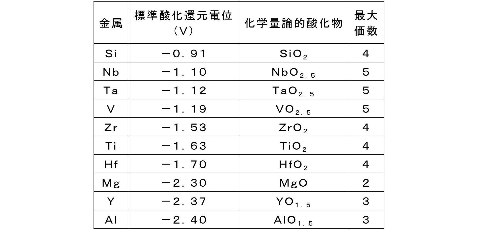
金属酸化物層中における金属酸化物の含有量は、本発明の効果を奏する限り特に限定されないが、金属酸化物層の全質量に対して50質量%以上であることが好ましく、80質量%以上であることがより好ましく、95質量%以上であることがさらに好ましく、98質量%以上であることが特に好ましく、100質量%である(すなわち、金属酸化物層は金属酸化物からなる)ことが最も好ましい。
金属酸化物以外で、該金属酸化物層に含まれうる化合物としては、上記金属の窒化物、窒酸化物、炭酸化物等を挙げることができる。
金属酸化物層の形成方法は、容易性の観点から、気相成膜法であることが好ましい。気相成膜法としては、特に制限されず、例えば、スパッタ法、蒸着法、イオンプレーティング法等の物理気相成長法(PVD)法、プラズマCVD(chemical vapordeposition)法、ALD(Atomic Layer Deposition)などの化学気相成長法が挙げられる。中でも、下層へのダメージを与えることなく成膜が可能となり、高い生産性を有することから、スパッタ法により形成することが好ましい。
スパッタ法による成膜は、2極スパッタリング、マグネトロンスパッタリング、中間的な周波数領域を用いたデュアルマグネトロン(DMS)スパッタリング、イオンビームスパッタリング、ECRスパッタリングなどを単独でまたは2種以上組み合わせて用いることができる。また、ターゲットの印加方式はターゲット種に応じて適宜選択され、DC(直流)スパッタリング、およびRF(高周波)スパッタリングのいずれを用いてもよい。また、金属モードと、酸化物モードの中間である遷移モードを利用した反応性スパッタ法も用いることができる。遷移領域となるようにスパッタ現象を制御することにより、高い成膜スピードで金属酸化物を成膜することが可能となるため好ましい。DCスパッタリングやDMSスパッタリングを行なう際には、そのターゲットに上記金属を用い、さらに、プロセスガス中に酸素を導入することで、上記金属を含む酸化物の薄膜を形成することができる。また、RF(高周波)スパッタリングで成膜する場合は、上記金属の酸化物のターゲットを用いることができる。プロセスガスに用いられる不活性ガスとしては、He、Ne、Ar、Kr、Xe等を用いることができ、Arを用いることが好ましい。さらに、プロセスガス中に酸素、窒素、二酸化炭素、一酸化炭素等を導入することで、金属の酸化物、窒化物、窒酸化物、炭酸化物等の遷移金属化合物薄膜を作ることができる。スパッタ法における成膜条件としては、印加電力、放電電流、放電電圧、時間等が挙げられるが、これらは、スパッタ装置や、膜の材料、膜厚等に応じて適宜選択することができる。
中でも、成膜レートがより高く、より高い生産性を有することから、金属の酸化物をターゲットとして用いるスパッタ法が好ましい。
金属酸化物層は、単層でもよいし2層以上の積層構造であってもよい。金属酸化物層が2層以上の積層構造である場合、各金属酸化物層に含まれる金属は、同じものであってもよいし異なるものであってもよい。
金属酸化物層の厚さ(2層以上の積層構造である場合はその総厚)は、特に制限されないが、1~500nmであることが好ましく、3~300nmであることが好ましく、5~200nmであることがより好ましい。この範囲であれば、ガスバリア層の酸化をより効率的に抑制し得る。
[長尺状の樹脂基材]
本発明に係る長尺状の樹脂基材(本明細書では、単に「樹脂基材」または「基材」とも称する)としては、具体的には、ポリエステル樹脂、メタクリル樹脂、メタクリル酸-マレイン酸共重合体、ポリスチレン樹脂、透明フッ素樹脂、ポリイミド樹脂、フッ素化ポリイミド樹脂、ポリアミド樹脂、ポリアミドイミド樹脂、ポリエーテルイミド樹脂、セルロースアシレート樹脂、ポリウレタン樹脂、ポリエーテルエーテルケトン樹脂、ポリカーボネート樹脂、脂環式ポリオレフィン樹脂、ポリアリレート樹脂、ポリエーテルスルホン樹脂、ポリスルホン樹脂、シクロオレフィンコポリマー、フルオレン環変性ポリカーボネート樹脂、脂環変性ポリカーボネート樹脂、フルオレン環変性ポリエステル樹脂、アクリロイル化合物などの熱可塑性樹脂を含む基材が挙げられる。該樹脂基材は、単独でもまたは2種以上組み合わせても用いることができる。
本発明に係る長尺状の樹脂基材(本明細書では、単に「樹脂基材」または「基材」とも称する)としては、具体的には、ポリエステル樹脂、メタクリル樹脂、メタクリル酸-マレイン酸共重合体、ポリスチレン樹脂、透明フッ素樹脂、ポリイミド樹脂、フッ素化ポリイミド樹脂、ポリアミド樹脂、ポリアミドイミド樹脂、ポリエーテルイミド樹脂、セルロースアシレート樹脂、ポリウレタン樹脂、ポリエーテルエーテルケトン樹脂、ポリカーボネート樹脂、脂環式ポリオレフィン樹脂、ポリアリレート樹脂、ポリエーテルスルホン樹脂、ポリスルホン樹脂、シクロオレフィンコポリマー、フルオレン環変性ポリカーボネート樹脂、脂環変性ポリカーボネート樹脂、フルオレン環変性ポリエステル樹脂、アクリロイル化合物などの熱可塑性樹脂を含む基材が挙げられる。該樹脂基材は、単独でもまたは2種以上組み合わせても用いることができる。
樹脂基材は耐熱性を有する素材からなることが好ましい。具体的には、線膨張係数が15ppm/K以上100ppm/K以下で、かつガラス転移温度(Tg)が100℃以上300℃以下の樹脂基材が使用される。該樹脂基材は、電子部品用途、ディスプレイ用積層フィルムとしての必要条件を満たしている。即ち、これらの用途に本発明に係るガスバリア性フィルムを用いる場合、ガスバリア性フィルムは、150℃以上の工程に曝されることがある。この場合、ガスバリア性フィルムにおける樹脂基材の線膨張係数が100ppm/Kを超えると、ガスバリア性フィルムを前記のような温度の工程に流す際に基板寸法が安定せず、熱膨張および収縮に伴い、遮断性能が劣化する不都合や、あるいは、熱工程に耐えられないという不具合が生じやすくなる。15ppm/K未満では、フィルムがガラスのように割れてしまいフレキシビリティが劣化する場合がある。
樹脂基材のTgや線膨張係数は、添加剤などによって調整することができる。樹脂基材として用いることができる熱可塑性樹脂のより好ましい具体例としては、例えば、ポリエチレンテレフタレート(PET:70℃)、ポリエチレンナフタレート(PEN:120℃)、ポリカーボネート(PC:140℃)、脂環式ポリオレフィン(例えば日本ゼオン株式会社製、ゼオノア(登録商標)1600:160℃)、ポリアリレート(PAr:210℃)、ポリエーテルスルホン(PES:220℃)、ポリスルホン(PSF:190℃)、シクロオレフィンコポリマー(COC:特開2001-150584号公報に記載の化合物:162℃)、ポリイミド(例えば三菱ガス化学株式会社製、ネオプリム(登録商標):260℃)、フルオレン環変性ポリカーボネート(BCF-PC:特開2000-227603号公報に記載の化合物:225℃)、脂環変性ポリカーボネート(IP-PC:特開2000-227603号公報に記載の化合物:205℃)、アクリロイル化合物(特開2002-80616号公報に記載の化合物:300℃以上)等が挙げられる(括弧内はTgを示す)。
本発明に係るガスバリア性フィルムは、有機EL素子等の電子デバイスとして利用されることから、樹脂基材は透明であることが好ましい。すなわち、光線透過率が通常80%以上、好ましくは85%以上、より好ましくは90%以上である。光線透過率は、JIS K7105:1981に記載された方法、すなわち積分球式光線透過率測定装置を用いて全光線透過率および散乱光量を測定し、全光線透過率から拡散透過率を引いて算出することができる。
ただし、本発明に係るガスバリア性フィルムをディスプレイ用途に用いる場合であっても、観察側に設置しない場合などは必ずしも透明性が要求されない。したがって、このような場合は、プラスチックフィルムとして不透明な材料を用いることもできる。不透明な材料としては、例えば、ポリイミド、ポリアクリロニトリル、公知の液晶ポリマーなどが挙げられる。
また、上記に挙げた樹脂基材は、未延伸フィルムでもよく、延伸フィルムでもよい。当該樹脂基材は、従来公知の一般的な方法により製造することが可能である。これらの樹脂基材の製造方法については、国際公開第2013/002026号の段落「0051」~「0055」の記載された事項を適宜採用することができる。
樹脂基材の表面は、密着性向上のための公知の種々の処理、例えばコロナ放電処理、火炎処理、酸化処理、またはプラズマ処理等を行っていてもよく、必要に応じて上記処理を組み合わせて行っていてもよい。
樹脂基材は、単層でもよいし2層以上の積層構造であってもよい。樹脂基材が2層以上の積層構造である場合、各層は同じ種類であってもよいし異なる種類であってもよい。
本発明に係る樹脂基材の厚さ(2層以上の積層構造である場合はその総厚)は、10~200μmであることが好ましく、20~150μmであることがより好ましい。
[炭素の組成比]
本発明のガスバリア性フィルムは、厚さ方向にX線光電子分光法による組成分析を行った際に得られる原子組成分布プロファイルにおいて、ケイ素と金属との原子組成比が1:1となる点の炭素の組成比(以下、単に「炭素組成比」とも称する)が、ケイ素、金属、窒素、酸素、および炭素の合計量を100atm%として、2.0atm%未満である。このような構成を有する本発明のガスバリア性フィルムは、高温高湿環境での耐久性に優れる。
本発明のガスバリア性フィルムは、厚さ方向にX線光電子分光法による組成分析を行った際に得られる原子組成分布プロファイルにおいて、ケイ素と金属との原子組成比が1:1となる点の炭素の組成比(以下、単に「炭素組成比」とも称する)が、ケイ素、金属、窒素、酸素、および炭素の合計量を100atm%として、2.0atm%未満である。このような構成を有する本発明のガスバリア性フィルムは、高温高湿環境での耐久性に優れる。
上記炭素組成比が、2.0atm%以上である場合、高温高湿環境での耐久性が低下する。当該炭素組成比は、好ましくは1.7atm%以下、より好ましくは1.5atm%以下である。
炭素組成比は、次のような方法で求めることができる。図1は、X線光電子分光法(XPS)による組成分析を行った際に得られる原子組成分布プロファイルの一例を示す図であり、後述の実施例14のガスバリア性フィルムから得られた、原子組成分布プロファイルを示す図である。図1のSiで示すケイ素分布曲線と、図1のNbで示す金属分布曲線との交点が、ケイ素と金属との原子組成比が1:1となる点である。図1のCで示す曲線は炭素分布曲線であり、上記交点のスパッタ深さにおける炭素の組成比を、この炭素分布曲線から求める。そして、図1には示していないが、同様のXPS組成分析で得られる窒素分布曲線および酸素分布曲線から、上記交点のスパッタ深さにおける窒素の組成比および酸素の組成比を求める。そしてこれらの分析結果から、ケイ素、金属、窒素、酸素、および炭素の合計量を100atm%として、上記交点のスパッタ深さにおける炭素の組成比を算出し、本明細書における炭素組成比とする。
本発明におけるXPS組成分析は、下記の条件で行ったものであるが、装置や測定条件が変わっても本発明の主旨に即した測定方法であれば問題なく適用できるものである。
≪XPS組成分析条件≫
・装置:アルバック・ファイ株式会社製、QUANTERASXM
・X線源:単色化Al-Kα
・測定領域:Si2p、C1s、N1s、O1s
・スパッタイオン:Ar(2keV)
・デプスプロファイル:一定時間スパッタ後、測定を繰り返す。1回の測定は、SiO2換算で、約0.84nmの厚さ分となるようにスパッタ時間を調整する
・定量:バックグラウンドをShirley法で求め、得られたピーク面積から相対感度係数法を用いて定量する。データ処理は、アルバック・ファイ株式会社製のMultiPakを用いる。
・装置:アルバック・ファイ株式会社製、QUANTERASXM
・X線源:単色化Al-Kα
・測定領域:Si2p、C1s、N1s、O1s
・スパッタイオン:Ar(2keV)
・デプスプロファイル:一定時間スパッタ後、測定を繰り返す。1回の測定は、SiO2換算で、約0.84nmの厚さ分となるようにスパッタ時間を調整する
・定量:バックグラウンドをShirley法で求め、得られたピーク面積から相対感度係数法を用いて定量する。データ処理は、アルバック・ファイ株式会社製のMultiPakを用いる。
このような炭素組成比は、後述のガスバリア性フィルムの製造方法における、保護フィルムの種類の選択、保護フィルムの剥離までの時間、ガスバリア層表面の洗浄、などの方法を適宜選択することにより、制御することができる。
中でも、より炭素組成比を低減させることができるという観点から、当該ガスバリア層は、ガスバリア層の表面を紫外線洗浄(UV洗浄)、水洗浄、オゾンプラズマ洗浄、大気中エキシマ洗浄、および酸素濃度1体積%以下の環境下で行うエキシマ洗浄からなる群より選択される少なくとも1つの洗浄処理をさらに行うことによって得られるものであることが好ましい。この洗浄処理については、後述する。
[種々の機能を有する層]
本発明のガスバリア性フィルムにおいては、種々の機能を有する層を設けることができる。
本発明のガスバリア性フィルムにおいては、種々の機能を有する層を設けることができる。
(アンカーコート層)
本発明に係るガスバリア層を形成する側の樹脂基材の表面には、樹脂基材とガスバリア層との密着性の向上を目的として、アンカーコート層を形成してもよい。
本発明に係るガスバリア層を形成する側の樹脂基材の表面には、樹脂基材とガスバリア層との密着性の向上を目的として、アンカーコート層を形成してもよい。
アンカーコート層に用いられるアンカーコート剤としては、ポリエステル樹脂、イソシアネート樹脂、ウレタン樹脂、アクリル樹脂、エチレンビニルアルコール樹脂、ビニル変性樹脂、エポキシ樹脂、変性スチレン樹脂、変性シリコン樹脂、およびアルキルチタネート等を単独でまたは2種以上組み合わせて使用することができる。
これらのアンカーコート剤には、従来公知の添加剤を加えることもできる。そして、上記のアンカーコート剤は、ロールコート、グラビアコート、ナイフコート、ディップコート、スプレーコート等の公知の方法により支持体上にコーティングし、溶剤、希釈剤等を乾燥除去することによりアンカーコーティングすることができる。上記のアンカーコート剤の塗布量としては、0.1~5.0g/m2(乾燥状態)程度が好ましい。
また、アンカーコート層は、物理蒸着法または化学蒸着法といった気相法により形成することもできる。例えば、特開2008-142941号公報に記載のように、接着性等を改善する目的で酸化ケイ素を主体とした無機膜を形成することもできる。あるいは、特開2004-314626号公報に記載されているようなアンカーコート層を形成することで、その上に気相法により無機薄膜を形成する際に、樹脂基材側から発生するガスをある程度遮断して、無機薄膜の組成を制御するといった目的でアンカーコート層を形成することもできる。
また、アンカーコート層の厚さは、特に制限されないが、0.5~10μm程度が好ましい。
(ハードコート層)
樹脂基材の表面(片面または両面)には、ハードコート層を有していてもよい。ハードコート層に含まれる材料の例としては、例えば、熱硬化性樹脂や活性エネルギー線硬化性樹脂が挙げられるが、成形が容易なことから、活性エネルギー線硬化性樹脂が好ましい。このような硬化性樹脂は、単独でもまたは2種以上組み合わせても用いることができる。
樹脂基材の表面(片面または両面)には、ハードコート層を有していてもよい。ハードコート層に含まれる材料の例としては、例えば、熱硬化性樹脂や活性エネルギー線硬化性樹脂が挙げられるが、成形が容易なことから、活性エネルギー線硬化性樹脂が好ましい。このような硬化性樹脂は、単独でもまたは2種以上組み合わせても用いることができる。
活性エネルギー線硬化性樹脂とは、紫外線や電子線のような活性エネルギー線の照射により架橋反応等を経て硬化する樹脂をいう。活性エネルギー線硬化性樹脂としては、エチレン性不飽和二重結合を有するモノマーを含む成分が好ましく用いられ、紫外線や電子線のような活性エネルギー線を照射することによって硬化させて、活性エネルギー線硬化性樹脂の硬化物を含む層、すなわちハードコート層が形成される。活性エネルギー線硬化性樹脂としては紫外線硬化性樹脂や電子線硬化性樹脂等が代表的なものとして挙げられるが、紫外線照射によって硬化する紫外線硬化性樹脂が好ましい。予めハードコート層が形成されている市販の樹脂基材を用いてもよい。
(平滑層)
本発明のガスバリア性フィルムにおいては、樹脂基材とガスバリア層との間に、平滑層を有してもよい。本発明に用いられる平滑層は、突起等が存在する樹脂基材の粗面を平坦化し、あるいは、樹脂基材に存在する突起によりガスバリア物層に生じうる凹凸やピンホールを防止して平坦化するために設けられる。このような平滑層は、基本的には感光性材料、または、熱硬化性材料を硬化させて作製される。
本発明のガスバリア性フィルムにおいては、樹脂基材とガスバリア層との間に、平滑層を有してもよい。本発明に用いられる平滑層は、突起等が存在する樹脂基材の粗面を平坦化し、あるいは、樹脂基材に存在する突起によりガスバリア物層に生じうる凹凸やピンホールを防止して平坦化するために設けられる。このような平滑層は、基本的には感光性材料、または、熱硬化性材料を硬化させて作製される。
平滑層の感光性材料としては、例えば、ラジカル反応性不飽和化合物を有するアクリレート化合物を含有する樹脂組成物、アクリレート化合物とチオール基を有するメルカプト化合物とを含有する樹脂組成物、エポキシアクリレート、ウレタンアクリレート、ポリエステルアクリレート、ポリエーテルアクリレート、ポリエチレングリコールアクリレート、グリセロールメタクリレート等の多官能アクリレートモノマーを溶解させた樹脂組成物等が挙げられる。具体的には、JSR株式会社製のUV硬化型有機/無機ハイブリッドハードコート材 OPSTAR(登録商標)シリーズを用いることができる。また、上記のような樹脂組成物の任意の混合物を使用することも可能であり、光重合性不飽和結合を分子内に1個以上有する反応性のモノマーを含有している感光性樹脂であれば特に制限はない。
熱硬化性材料として具体的には、クラリアント社製のトゥットプロムシリーズ(有機ポリシラザン)、セラミックコート株式会社製のSP COAT耐熱クリアー塗料、株式会社アデカ製のナノハイブリッドシリコーン、DIC株式会社製のユニディック(登録商標)V-8000シリーズ、EPICLON(登録商標)EXA-4710(超高耐熱性エポキシ樹脂)、信越化学工業株式会社製の各種シリコン樹脂、日東紡株式会社製の無機・有機ナノコンポジット材料SSGコート、アクリルポリオールとイソシアネートプレポリマーとからなる熱硬化性ウレタン樹脂、フェノール樹脂、尿素メラミン樹脂、エポキシ樹脂、不飽和ポリエステル樹脂、シリコン樹脂等が挙げられる。この中でも特に耐熱性を有するエポキシ樹脂ベースの材料であることが好ましい。
平滑層の形成方法は、特に制限はないが、スピンコーティング法、スプレー法、ブレードコーティング法、ディップ法等のウエットコーティング法、あるいは、蒸着法等のドライコーティング法により形成することが好ましい。
平滑層の形成では、上述の感光性樹脂に、必要に応じて酸化防止剤、紫外線吸収剤、可塑剤等の添加剤を加えることができる。また、平滑層の積層位置に関係なく、いずれの平滑層においても、成膜性向上および膜のピンホール発生防止等のために適切な樹脂や添加剤を使用してもよい。
平滑層の厚さとしては、フィルムの耐熱性を向上させ、フィルムの光学特性のバランス調整を容易にする観点から、1~10μmの範囲が好ましく、2~7μmの範囲がより好ましい。
平滑層の平滑性は、JIS B 0601:2013で規定される表面粗さで表現される値で、十点平均粗さRzが、10nm以上、30nm以下であることが好ましい。この範囲であれば、ガスバリア層を塗布形式で塗布した場合であっても、ワイヤーバー、ワイヤレスバー等の塗布方式で、平滑層表面に塗工手段が接触する場合であっても塗布性が損なわれることが少なく、また、塗布後の凹凸を平滑化することも容易である。
[ガスバリア性フィルムの製造方法]
本発明のガスバリア性フィルムの製造方法は、特に制限されないが、長尺状の樹脂基材上にケイ素および窒素を含むガスバリア層を形成する工程と、前記ガスバリア層の表面上に保護フィルムを貼付し、得られる積層体を巻き取った後、前記保護フィルムを剥離する工程と、V、Nb、Ta、Ti、Zr、Hf、Mg、Y、およびAlからなる群より選択される少なくとも1種の金属の酸化物を含有する金属酸化物層を形成する工程と、を含む製造方法が好ましい。
本発明のガスバリア性フィルムの製造方法は、特に制限されないが、長尺状の樹脂基材上にケイ素および窒素を含むガスバリア層を形成する工程と、前記ガスバリア層の表面上に保護フィルムを貼付し、得られる積層体を巻き取った後、前記保護フィルムを剥離する工程と、V、Nb、Ta、Ti、Zr、Hf、Mg、Y、およびAlからなる群より選択される少なくとも1種の金属の酸化物を含有する金属酸化物層を形成する工程と、を含む製造方法が好ましい。
ガスバリア層を形成する工程および金属酸化物層を形成する工程は、上述の通りであるため、ここでは説明を省略する。以下では、保護フィルムを貼付し巻き取り、剥離する工程と、その後行われうる洗浄工程とについて説明する。
(保護フィルムを貼付、剥離する工程)
本工程では、長尺状の樹脂基材上にケイ素および窒素を含むガスバリア層を形成した後、ガスバリア層上に保護フィルムを貼付し積層体を得、該積層体を巻き取った後、その後保護フィルムを剥離する。
本工程では、長尺状の樹脂基材上にケイ素および窒素を含むガスバリア層を形成した後、ガスバリア層上に保護フィルムを貼付し積層体を得、該積層体を巻き取った後、その後保護フィルムを剥離する。
保護フィルムの基材としては、特に制限されず、例えば、ポリエチレンテレフタレート、ポリエチレンナフタレート等のポリエステル樹脂、トリアセチルセルロース等のセルロース樹脂、ポリメチル(メタ)アクリレート等のアクリル樹脂、ポリスチレンやアクリロニトリル・スチレン共重合体等のスチレン樹脂、ポリカーボネート樹脂、ポリエチレン、ポリプロピレン、エチレン・プロピレン共重合体等のオレフィン樹脂、塩化ビニル樹脂、ポリアミド樹脂、イミド樹脂、ポリフェニレンスルフィド樹脂、ポリエーテルスルホン樹脂、塩化ビニリデン樹脂、ビニルアルコール樹脂、ビニルブチラール樹脂、アリレート樹脂、ポリオキシメチレン樹脂、エポキシ樹脂、またはこれらの樹脂のブレンド物などが挙げられる。本発明においては、良好な巻姿を得るためには、ポリエチレン、ポリプロピレン等のクッション性を有する素材が好ましい。
保護フィルムは粘着層を有していてもよい。粘着層を構成する粘着剤としては、通常、用いられる再剥離用粘着剤(アクリル系、ゴム系、合成ゴム系など)等が挙げられる。
保護フィルムは、市販品を用いてもよい。市販品の例としては、例えば、東レフィルム加工株式会社製のトレテック(登録商標)シリーズ(7111、7412K6、7531、7721、7332、7121)、三菱エンジニアリングプラスチックス株式会社製のユーピロン(登録商標)シリーズ、タマポリ株式会社製のGFシリーズ、フタムラ化学株式会社製の010M等が挙げられる。
保護フィルムを貼付する方法は、特に限定されず、例えば、製膜装置を走行しているフィルムラインの下側または上側に設置された繰り出し機(または巻き出し機)等のモーターを有する駆動軸に保護フィルムロールをセットし、ガスバリア層形成済のフィルムと保護フィルムとを2つのゴムロールにより押し付けることにより貼り合わせる等の方法が挙げられる。
保護フィルムを貼付した後、得られる積層体をロール状に巻き取る。より具体的には、例えば、巻取機に巻き芯をセットし、当該巻き芯に保護フィルム付き積層体を巻きつけ、積層体のラインスピードとほぼ同じ速度になるように、巻取速度を調整する。
次に、保護フィルムを剥離する。剥離の方法は、特に限定されず、例えば、トルクモーター等の駆動軸(巻き取りローラー)を備えた巻き取り装置に保護フィルムを巻き取らせ剥離する等の方法が挙げられる。
保護フィルムを貼付してから剥離するまでの時間は、24時間以内であることが好ましく、18時間以内であることがより好ましく、12時間以内であることがさらに好ましい。このように剥離するまでの時間を短くすることにより、特に保護フィルムの粘着層に含まれる化合物によるガスバリア層表面の汚染をより低減することができ、炭素組成比をより低減することができる。これにより、高温高湿環境における耐久性に優れたガスバリア性フィルムを得ることができる。
ただし、保護フィルムを貼付してから剥離するまでの時間が24時間を超えても、金属酸化物層を形成する前に、下記のようなガスバリア層の表面を洗浄する洗浄工程を行えば、炭素組成比を低減させることができ、好ましい。無論、保護フィルムを貼付してから剥離するまでの時間が24時間以内であっても、さらに下記の洗浄工程を行うことにより、炭素組成比をさらに低減させることができ、好ましい。
(洗浄工程)
本工程では、保護フィルムを剥離した後、ガスバリア層上に金属酸化物層を形成するより前に、ガスバリア層表面を洗浄する工程である。この洗浄により、特に保護フィルムの粘着層に含まれる化合物によるガスバリア層表面の汚染をさらに低減することができ、炭素組成比をさらに低減することができる。
本工程では、保護フィルムを剥離した後、ガスバリア層上に金属酸化物層を形成するより前に、ガスバリア層表面を洗浄する工程である。この洗浄により、特に保護フィルムの粘着層に含まれる化合物によるガスバリア層表面の汚染をさらに低減することができ、炭素組成比をさらに低減することができる。
本工程で行われる洗浄処理は、具体的には、紫外線洗浄、水洗浄、オゾンプラズマ洗浄、大気中エキシマ洗浄、および酸素濃度1体積%以下の環境下で行うエキシマ洗浄からなる群より選択される少なくとも1つが好ましい。
紫外線洗浄は、例えば低圧水銀ランプを用いてガスバリア層表面を洗浄する乾式処理である。紫外線の照射時間(洗浄時間)は30秒~20分が好ましい。
水処理は、例えば周波数150kHzの超音波を発する超音波洗浄機を用いてガスバリア層表面を洗浄する湿式処理である。洗浄時の温度は10~50℃が好ましく、洗浄時間は30秒~20分が好ましい。
オゾンプラズマ洗浄は、主に真空中で高周波電源等をトリガーとしてオゾンを励起させ、反応性の高い「プラズマ状態」にしたものを用いてガスバリア層表面を洗浄する乾式処理である。
エキシマ洗浄は、172nmを発光するキセノンエキシマランプを用いてガスバリア層表面を洗浄する乾式処理である。洗浄時の雰囲気は、大気雰囲気下でもよく(大気中エキシマ洗浄)、また酸素濃度1体積%以下の環境下であってもよい。
[短尺状のガスバリア性フィルム]
本発明の長尺状のガスバリア性フィルムは、短尺状に裁断して用いられてもよい。すなわち、本発明は、本発明の長尺状のガスバリア性フィルムを裁断して得られる短尺状のガスバリア性フィルムを提供する。また、本発明は、本発明の製造方法により長尺状のガスバリア性フィルムを得た後、前記長尺状のガスバリア性フィルムを裁断することを含む、短尺状のガスバリア性フィルムの製造方法を提供する。本発明の短尺状のガスバリア性フィルムは、上記長尺状のガスバリア性フィルムと同様に、高温高湿環境での耐久性に優れる。
本発明の長尺状のガスバリア性フィルムは、短尺状に裁断して用いられてもよい。すなわち、本発明は、本発明の長尺状のガスバリア性フィルムを裁断して得られる短尺状のガスバリア性フィルムを提供する。また、本発明は、本発明の製造方法により長尺状のガスバリア性フィルムを得た後、前記長尺状のガスバリア性フィルムを裁断することを含む、短尺状のガスバリア性フィルムの製造方法を提供する。本発明の短尺状のガスバリア性フィルムは、上記長尺状のガスバリア性フィルムと同様に、高温高湿環境での耐久性に優れる。
長尺状のガスバリア性フィルムを裁断する手段としては、手作業による裁断のほか、自動裁断機による裁断が挙げられる。得られる短尺状のガスバリア性フィルムの大きさは、特に制限されない。
[電子デバイス]
本発明の長尺状または短尺状のガスバリア性フィルムは、空気中の化学成分(酸素、水、窒素酸化物、硫黄酸化物、オゾン等)によって性能が劣化するデバイスに好ましく適用できる。すなわち、本発明は、本発明の長尺状のガスバリア性フィルムまたは本発明の製造方法により得られる長尺状のガスバリア性フィルムを用いた電子デバイスを提供する。
本発明の長尺状または短尺状のガスバリア性フィルムは、空気中の化学成分(酸素、水、窒素酸化物、硫黄酸化物、オゾン等)によって性能が劣化するデバイスに好ましく適用できる。すなわち、本発明は、本発明の長尺状のガスバリア性フィルムまたは本発明の製造方法により得られる長尺状のガスバリア性フィルムを用いた電子デバイスを提供する。
本発明の電子デバイスで用いられる電子デバイス本体の例としては、例えば、有機エレクトロルミネッセンス素子(有機EL素子)、液晶表示素子(LCD)、薄膜トランジスタ、タッチパネル、電子ペーパー、太陽電池(PV)等を挙げることができる。本発明の効果がより効率的に得られるという観点から、該電子デバイス本体は有機EL素子または太陽電池が好ましく、有機EL素子がより好ましい。
本発明の効果を、以下の実施例および比較例を用いて説明する。ただし、本発明の技術的範囲が以下の実施例のみに制限されるわけではない。
(実施例1:ガスバリア性フィルム1の作製)
〔ガスバリア層形成用塗布液の調製〕
ガスバリア層は、下記に示すようなポリシラザンを含む塗布液を、下記樹脂基材上に塗布および乾燥して塗膜を形成し、真空紫外線照射による改質を行って形成した。
〔ガスバリア層形成用塗布液の調製〕
ガスバリア層は、下記に示すようなポリシラザンを含む塗布液を、下記樹脂基材上に塗布および乾燥して塗膜を形成し、真空紫外線照射による改質を行って形成した。
パーヒドロポリシラザンを20質量%含むジブチルエーテル溶液(AZエレクトロニックマテリアルズ株式会社製、NN120-20)と、アミン触媒(N,N,N',N'-テトラメチル-1,6-ジアミノヘキサン(TMDAH))を含むパーヒドロポリシラザン20質量%のジブチルエーテル溶液(AZエレクトロニックマテリアルズ株式会社製、NAX120-20)とを、4:1(質量比)の割合で混合し、さらに乾燥膜厚調整のためジブチルエーテルで適宜希釈し、塗布液を調製した。
〔樹脂基材〕
両面ハードコート層付きポリエチレンテレフタレートフィルム(全厚み:136μm、PET厚み:125μm、株式会社きもと製、商品名:KBフィルム(商標)125G1SBF、幅:1230mm、長さ:100m)を用いた。
両面ハードコート層付きポリエチレンテレフタレートフィルム(全厚み:136μm、PET厚み:125μm、株式会社きもと製、商品名:KBフィルム(商標)125G1SBF、幅:1230mm、長さ:100m)を用いた。
図3に示すガスバリア性フィルム製造装置20を用いて、ガスバリア性フィルム1を製造した。図3は、ガスバリア性フィルムを製造する際に用いる装置の一例を示す概略図であり、いわゆるロール・トゥ・ロール方式の装置である。図3に示す装置は、送り出しローラー22aと、搬送ローラー23a~23hと、塗布手段24と、乾燥手段25と、改質処理手段28と、ニップロール23iおよび23jと、送り出しローラー22cと、タッチローラー23kと、巻き取りローラー22bと、を備えている。
〔第一工程〕
送り出しローラー22aから両面ハードコート層付きの上記樹脂基材21を、塗布手段24に搬送した。上記で調製したガスバリア層形成用塗布液をスロットダイコーターにて、乾燥膜厚250nmになるように塗布し、次に、乾燥手段25にて80℃で2分間加熱処理を行い、塗膜を形成した。
送り出しローラー22aから両面ハードコート層付きの上記樹脂基材21を、塗布手段24に搬送した。上記で調製したガスバリア層形成用塗布液をスロットダイコーターにて、乾燥膜厚250nmになるように塗布し、次に、乾燥手段25にて80℃で2分間加熱処理を行い、塗膜を形成した。
上記で形成した塗膜は、改質処理手段28に搬送され、下記の改質方法に従い、真空紫外線照射(株式会社エム・ディ・コム製エキシマ照射装置MODEL:MECL-M-1-200、波長172nm、ステージ温度100℃、酸素濃度0.1体積%)を施して、ガスバリア層を形成した。
(真空紫外線照射による改質方法)
真空紫外線照射は、改質処理手段28として、図2の断面模式図で示した真空紫外線照射装置を用いて行った。
真空紫外線照射は、改質処理手段28として、図2の断面模式図で示した真空紫外線照射装置を用いて行った。
図2の装置チャンバー10の内部に水蒸気を除去し、酸素濃度を0.1体積%に維持した。ポリシラザン塗膜が形成された基材試料15が試料ステージ14に搬送され、試料ステージ14を100℃に維持しながら、所望の照射エネルギーに合わせて一定の速度で水平移動させた。この際、ポリシラザン塗膜を上に向かせ、かつポリシラザン塗膜の表面とエキシマランプ12の管面との最短距離が3mmとなるように試料ステージ14の高さを調整した。
真空紫外線照射工程でポリシラザン塗膜表面に照射されるエネルギーは、浜松ホトニクス株式会社製の紫外線積算光量計:C8026/H8025 UV POWER METERを用い、172nmのセンサヘッドを用いて測定した。測定に際しては、Xeエキシマランプ管面とセンサヘッドの測定面との最短距離が3mmとなるように、センサヘッドを試料ステージ14中央に設置し、かつ、装置チャンバー10内の雰囲気が、真空紫外線照射工程と同一の酸素濃度となるように窒素と酸素とを供給し、試料ステージ14を0.5m/minの速度で移動させて測定を行った。測定に先立ち、Xeエキシマランプ12の照度を安定させるため、Xeエキシマランプ12の点灯後に10分間のエージング時間を設け、その後試料ステージ14を移動させて測定を開始した。
この測定で得られた照射エネルギーを元に、試料ステージの移動速度を調整することで6.0J/cm2の照射エネルギーとなるように調整した。尚、真空紫外線照射に際しては、10分間のエージング後に行った。
〔第二工程〕
続いて、真空紫外線照射処理後、ガスバリア層が形成された樹脂基材21は、ニップロール23iおよび23jに搬送された。それと同時に、送り出しローラー22cから保護フィルム27として、010M(フタムラ化学株式会社製)がニップロール23iおよび23jに搬送され、23℃で20N/cmの線圧で速度2m/minで、上記で形成されたガスバリア層上に貼り合わせ、タッチローラー23kと接触させ、面圧が0.6MPaとなるように、100mをロール状に巻き取り、フィルム積層体1を得た。
続いて、真空紫外線照射処理後、ガスバリア層が形成された樹脂基材21は、ニップロール23iおよび23jに搬送された。それと同時に、送り出しローラー22cから保護フィルム27として、010M(フタムラ化学株式会社製)がニップロール23iおよび23jに搬送され、23℃で20N/cmの線圧で速度2m/minで、上記で形成されたガスバリア層上に貼り合わせ、タッチローラー23kと接触させ、面圧が0.6MPaとなるように、100mをロール状に巻き取り、フィルム積層体1を得た。
保護フィルム貼付から12時間経過した後、巻き取りローラーを備えた巻き取り装置を用いて保護フィルムを剥がし、はさみを用いて10cm×10cmの大きさにフィルムを1枚裁断した。その裁断したフィルムを用い、スパッタ法によりガスバリア層上に膜厚15nmの金属酸化物層を成膜した。成膜は、ターゲットとしてTa2O5ターゲットを用い、プロセスガスにはArとO2とを用いたRFスパッタにより、金属酸化物層の組成がTa2O4.4となるように酸素分圧を調整した。
このようにして、ガスバリア性フィルム1を作製した。
(実施例2:ガスバリア性フィルム2の作製)
金属酸化物層を下記のようにして成膜したこと以外は、実施例1と同様にして、ガスバリア性フィルム2を作製した。
金属酸化物層を下記のようにして成膜したこと以外は、実施例1と同様にして、ガスバリア性フィルム2を作製した。
金属酸化物層をスパッタ法により成膜した。ターゲットとして酸素欠損型TiO2ターゲットを用い、プロセスガスにはArとO2とを用いたDCスパッタにより、膜厚15nmの金属酸化物層を樹脂基材上に成膜した。成膜は、組成がTiO2となるように酸素分圧を調整した。
(実施例3:ガスバリア性フィルム3の作製)
金属酸化物層を下記のようにして成膜したこと以外は、実施例1と同様にして、ガスバリア性フィルム3を作製した。
金属酸化物層を下記のようにして成膜したこと以外は、実施例1と同様にして、ガスバリア性フィルム3を作製した。
金属酸化物層をスパッタ法により成膜した。ターゲットとしてZrターゲットを用い、プロセスガスにはArとO2とを用いたDCスパッタにより、膜厚15nmの金属酸化物層を樹脂基材上に成膜した。成膜は、組成がZrO2となるように酸素分圧を調整した。
(実施例4:ガスバリア性フィルム4の作製)
ポリシラザン改質時の真空紫外線の照射エネルギーを3.0J/cm2に変更し、かつ金属酸化物層を下記のように形成したこと以外は、実施例1と同様にして、ガスバリア性フィルム4を作製した。
ポリシラザン改質時の真空紫外線の照射エネルギーを3.0J/cm2に変更し、かつ金属酸化物層を下記のように形成したこと以外は、実施例1と同様にして、ガスバリア性フィルム4を作製した。
金属酸化物層をスパッタ法により成膜した。ターゲットとして酸素欠損型Nb2O5ターゲットを用い、プロセスガスにはArとO2とを用いたDCスパッタにより、膜厚15nmのガスバリア層を樹脂基材上に成膜した。成膜は、ガスバリア層の組成がNb2O3となるように酸素分圧を調整した。
(実施例5:ガスバリア性フィルム5の作製)
ポリシラザン改質時の真空紫外線の照射エネルギーを6.0J/cm2に変更したこと以外は、実施例4と同様にして、ガスバリア性フィルム5を作製した。
ポリシラザン改質時の真空紫外線の照射エネルギーを6.0J/cm2に変更したこと以外は、実施例4と同様にして、ガスバリア性フィルム5を作製した。
(実施例6:ガスバリア性フィルム6の作製)
金属酸化物層を成膜する前に、下記のようなガスバリア層の水洗浄を行ったこと以外は、実施例5と同様にして、ガスバリア性フィルム6を作製した。
金属酸化物層を成膜する前に、下記のようなガスバリア層の水洗浄を行ったこと以外は、実施例5と同様にして、ガスバリア性フィルム6を作製した。
≪水洗浄≫
ガスバリア層を形成したフィルムを、純水を満たした周波数150Hzの超音波を発する超音波槽に2分間浸け(純水の温度23℃)、水洗浄を行い、その後乾燥した。下記表1では、この水洗浄を(ア)と表す。
ガスバリア層を形成したフィルムを、純水を満たした周波数150Hzの超音波を発する超音波槽に2分間浸け(純水の温度23℃)、水洗浄を行い、その後乾燥した。下記表1では、この水洗浄を(ア)と表す。
(実施例7:ガスバリア性フィルム7の作製)
保護フィルムを剥がすまでの時間を48時間としたこと以外は、実施例6と同様にして、ガスバリア性フィルム7を作製した。
保護フィルムを剥がすまでの時間を48時間としたこと以外は、実施例6と同様にして、ガスバリア性フィルム7を作製した。
(実施例8:ガスバリア性フィルム8の作製)
保護フィルムを、東レフィルム加工株式会社製、トレテック(登録商標)7332に変更したこと以外は、実施例7と同様にして、ガスバリア性フィルム8を作製した。
保護フィルムを、東レフィルム加工株式会社製、トレテック(登録商標)7332に変更したこと以外は、実施例7と同様にして、ガスバリア性フィルム8を作製した。
(実施例9:ガスバリア性フィルム9の作製)
保護フィルムを剥がすまでの時間を48時間としたこと以外は、実施例8と同様にして、ガスバリア性フィルム9を作製した。
保護フィルムを剥がすまでの時間を48時間としたこと以外は、実施例8と同様にして、ガスバリア性フィルム9を作製した。
(実施例10:ガスバリア性フィルム10の作製)
上記の水洗浄に代えて、下記のようなガスバリア層のUV洗浄を行ったこと以外は、実施例9と同様にして、ガスバリア性フィルム10を作製した。
上記の水洗浄に代えて、下記のようなガスバリア層のUV洗浄を行ったこと以外は、実施例9と同様にして、ガスバリア性フィルム10を作製した。
≪UV洗浄≫
セン特殊光源株式会社製の卓上型表面処理装置、型番PL32-200を用い、光源として低圧水銀ランプ(型番:EUV200WS-18)を用い、ガスバリア層表面とランプ管面との距離10mm、照射時間5分で、主波長254nmの紫外線を照射する処理を行った。下記表1では、このUV洗浄を(イ)と表す。
セン特殊光源株式会社製の卓上型表面処理装置、型番PL32-200を用い、光源として低圧水銀ランプ(型番:EUV200WS-18)を用い、ガスバリア層表面とランプ管面との距離10mm、照射時間5分で、主波長254nmの紫外線を照射する処理を行った。下記表1では、このUV洗浄を(イ)と表す。
(実施例11:ガスバリア性フィルム11の作製)
水洗浄の前に、実施例10に記載のUV洗浄を行ったこと以外は、実施例9と同様にして、ガスバリア性フィルム11を作製した。
水洗浄の前に、実施例10に記載のUV洗浄を行ったこと以外は、実施例9と同様にして、ガスバリア性フィルム11を作製した。
(実施例12:ガスバリア性フィルム12の作製)
下記のようにして金属酸化物層を成膜したこと以外は、実施例11と同様にして、ガスバリア性フィルム12を作製した。
下記のようにして金属酸化物層を成膜したこと以外は、実施例11と同様にして、ガスバリア性フィルム12を作製した。
金属酸化物層をスパッタ法により成膜した。ターゲットとしてTa2O5ターゲットを用い、プロセスガスにはArとO2とを用いたRFスパッタにより、金属酸化物層の組成がTa2O4.4となるように酸素分圧を調整した。
(実施例13:ガスバリア性フィルム13の作製)
下記のようにして金属酸化物層を成膜したこと以外は、実施例11と同様にして、ガスバリア性フィルム13を作製した。
下記のようにして金属酸化物層を成膜したこと以外は、実施例11と同様にして、ガスバリア性フィルム13を作製した。
金属酸化物層をスパッタ法により成膜した。ターゲットとして酸素欠損型TiO2ターゲットを用い、プロセスガスにはArとO2とを用いたDCスパッタにより、膜厚15nmの金属酸化物層を樹脂基材上に成膜した。成膜は、組成がTiO2となるように酸素分圧を調整した。
(実施例14:ガスバリア性フィルム14の作製)
保護フィルムをフタムラ化学株式会社製、010Mに変更し、かつ下記のようにして金属酸化物層を成膜したこと以外は、実施例11と同様にして、ガスバリア性フィルム14を作製した。
保護フィルムをフタムラ化学株式会社製、010Mに変更し、かつ下記のようにして金属酸化物層を成膜したこと以外は、実施例11と同様にして、ガスバリア性フィルム14を作製した。
金属酸化物層をスパッタ法により成膜した。ターゲットとして酸素欠損型Nb2O5ターゲットを用い、プロセスガスにはArとO2とを用いたDCスパッタにより、膜厚15nmのガスバリア層を樹脂基材上に成膜した。成膜は、ガスバリア層の組成がNb2O3となるように酸素分圧を調整した。
(実施例15:ガスバリア性フィルム15の作製)
保護フィルムを剥がすまでの時間を12時間としたこと以外は、実施例14と同様にして、ガスバリア性フィルム15を作製した。
保護フィルムを剥がすまでの時間を12時間としたこと以外は、実施例14と同様にして、ガスバリア性フィルム15を作製した。
(比較例1:ガスバリア性フィルム16の作製)
保護フィルムを剥がすまでの時間を48時間としたこと以外は、実施例5と同様にしてガスバリア性フィルム16を作製した。
保護フィルムを剥がすまでの時間を48時間としたこと以外は、実施例5と同様にしてガスバリア性フィルム16を作製した。
(比較例2:ガスバリア性フィルム17の作製)
水洗浄を行わなかったこと以外は、実施例8と同様にして、ガスバリア性フィルム17を作製した。
水洗浄を行わなかったこと以外は、実施例8と同様にして、ガスバリア性フィルム17を作製した。
(比較例3:ガスバリア性フィルム18の作製)
水洗浄を行わなかったこと以外は、実施例9と同様にして、ガスバリア性フィルム18を作製した。
水洗浄を行わなかったこと以外は、実施例9と同様にして、ガスバリア性フィルム18を作製した。
(比較例4:ガスバリア性フィルム19の作製)
保護フィルムを、東レフィルム加工株式会社製、トレテック(登録商標)7332に変更したこと以外は、実施例1と同様にして、ガスバリア性フィルム19を作製した。
保護フィルムを、東レフィルム加工株式会社製、トレテック(登録商標)7332に変更したこと以外は、実施例1と同様にして、ガスバリア性フィルム19を作製した。
(比較例5:ガスバリア性フィルム20の作製)
保護フィルムを、東レフィルム加工株式会社製、トレテック(登録商標)7332に変更したこと以外は、実施例2と同様にして、ガスバリア性フィルム20を作製した。
保護フィルムを、東レフィルム加工株式会社製、トレテック(登録商標)7332に変更したこと以外は、実施例2と同様にして、ガスバリア性フィルム20を作製した。
(比較例6:ガスバリア性フィルム21の作製)
保護フィルムを、東レフィルム加工株式会社製、トレテック(登録商標)7332に変更したこと以外は、実施例3と同様にして、ガスバリア性フィルム21を作製した。
保護フィルムを、東レフィルム加工株式会社製、トレテック(登録商標)7332に変更したこと以外は、実施例3と同様にして、ガスバリア性フィルム21を作製した。
(比較例7:ガスバリア性フィルム22の作製)
ポリシラザン改質時の真空紫外線の照射エネルギーを3.0J/cm2に変更したこと以外は、比較例3と同様にして、ガスバリア性フィルム22を作製した。
ポリシラザン改質時の真空紫外線の照射エネルギーを3.0J/cm2に変更したこと以外は、比較例3と同様にして、ガスバリア性フィルム22を作製した。
(比較例8:ガスバリア性フィルム23の作製)
保護フィルムを使用しなかったこと以外は、比較例7と同様にして、ガスバリア性フィルム23を作製した。
保護フィルムを使用しなかったこと以外は、比較例7と同様にして、ガスバリア性フィルム23を作製した。
(評価方法)
<炭素組成比>
XPS組成分析により、厚さ方向の組成分布プロファイルを測定し、ケイ素と金属との原子組成比が1:1となるスパッタ深さでの炭素の組成比を算出した。同様のXPS組成分析で得られる窒素分布曲線および酸素分布曲線から、上記交点のスパッタ深さにおける窒素の組成比および酸素の組成比を求め、これらの分析結果から、ケイ素、金属、窒素、酸素、および炭素の合計量を100atm%として、上記交点のスパッタ深さにおける炭素の組成比を算出した。
<炭素組成比>
XPS組成分析により、厚さ方向の組成分布プロファイルを測定し、ケイ素と金属との原子組成比が1:1となるスパッタ深さでの炭素の組成比を算出した。同様のXPS組成分析で得られる窒素分布曲線および酸素分布曲線から、上記交点のスパッタ深さにおける窒素の組成比および酸素の組成比を求め、これらの分析結果から、ケイ素、金属、窒素、酸素、および炭素の合計量を100atm%として、上記交点のスパッタ深さにおける炭素の組成比を算出した。
≪XPS組成分析条件≫
・装置:アルバック・ファイ株式会社製、QUANTERASXM
・X線源:単色化Al-Kα
・スパッタイオン:Ar(2keV)
・デプスプロファイル:一定時間スパッタ後、測定を繰り返す。1回の測定は、SiO2換算で、約0.84nmの厚さ分となるようにスパッタ時間を調整した
・定量:バックグラウンドをShirley法で求め、得られたピーク面積から相対感度係数法を用いて定量した。データ処理は、アルバック・ファイ株式会社製のMultiPakを用いた。
・装置:アルバック・ファイ株式会社製、QUANTERASXM
・X線源:単色化Al-Kα
・スパッタイオン:Ar(2keV)
・デプスプロファイル:一定時間スパッタ後、測定を繰り返す。1回の測定は、SiO2換算で、約0.84nmの厚さ分となるようにスパッタ時間を調整した
・定量:バックグラウンドをShirley法で求め、得られたピーク面積から相対感度係数法を用いて定量した。データ処理は、アルバック・ファイ株式会社製のMultiPakを用いた。
<水蒸気バリア性(WVTR)>
以下の測定方法に従って、各ガスバリア性フィルムの水蒸気バリア性を評価した。
以下の測定方法に従って、各ガスバリア性フィルムの水蒸気バリア性を評価した。
・装置
蒸着装置:日本電子株式会社製、真空蒸着装置JEE-400
恒温恒湿度オーブン:Yamato Humidic ChamberIG47M
水分と反応して腐食する金属:カルシウム(粒状)
水蒸気不透過性の金属:アルミニウム(φ3~5mm、粒状)
・水蒸気バリア性評価用セルの作製
真空蒸着装置(日本電子株式会社製、真空蒸着装置 JEE-400)を用い、それぞれのガスバリア性フィルムの表面に金属カルシウムを蒸着させた。その後、乾燥窒素ガス雰囲気下で、厚さ0.2mmの石英ガラスに封止用紫外線硬化樹脂(ナガセケムテックス株式会社製)を介して金属カルシウム蒸着面を対面させて接着し、紫外線を照射することで、評価用セルを作製した。
得られた試料(評価用セル)を60℃、90%RHの高温高湿下で保存し、金属カルシウムが100%腐食するまでにかかる時間を測定した。
なお、ガスバリア性フィルム面以外からの水蒸気の透過がないことを確認するために、比較試料としてガスバリア性フィルムの代わりに、厚さ0.2mmの石英ガラス板を用いて金属カルシウムを蒸着した試料を、上記と同様に60℃、90%RHの高温高湿下で保存し、1000時間経過後でも金属カルシウム腐食が発生しないことを確認した。
このようにして、各ガスバリア性フィルムの100%腐食時間を下記5段階にて評価した。ランク5~4が実用可能である。
≪評価基準≫
ランク5:100%腐食時間が1000時間以上
ランク4:100%腐食時間が500時間以上1000時間未満
ランク3:100%腐食時間が300時間以上500時間未満
ランク2:100%腐食時間が100時間以上300時間未満
ランク1:100%腐食時間が100時間未満。
ランク5:100%腐食時間が1000時間以上
ランク4:100%腐食時間が500時間以上1000時間未満
ランク3:100%腐食時間が300時間以上500時間未満
ランク2:100%腐食時間が100時間以上300時間未満
ランク1:100%腐食時間が100時間未満。
各実施例および比較例のガスバリア性フィルムの製造条件および評価結果を、下記表1に示す。
上記表1の結果から、実施例1~15のガスバリア性フィルムは、60℃90%RHという高温高湿環境での耐久性に優れることがわかる。
なお、本出願は、2015年5月1日に出願された日本特許出願第2015-094409号に基づいており、その開示内容は、参照により全体として引用されている。
Claims (14)
- 長尺状の樹脂基材上に設けられるケイ素および窒素を含有するガスバリア層と、
前記ガスバリア層上に接して設けられ、V、Nb、Ta、Ti、Zr、Hf、Mg、Y、およびAlからなる群より選択される少なくとも1種の金属の酸化物を含有する金属酸化物層と、
を有する長尺状のガスバリア性フィルムであって、
前記ガスバリア性フィルムの厚さ方向にX線光電子分光法による組成分析を行った際に得られる原子組成分布プロファイルにおいて、ケイ素と金属との原子組成比が1:1となる際の、炭素の組成比が、ケイ素、金属、窒素、酸素、および炭素の合計量を100atm%として、2.0atm%未満である、長尺状のガスバリア性フィルム。 - 前記金属がNbである、請求項1に記載の長尺状のガスバリア性フィルム。
- 前記ガスバリア層は、ポリシラザンを含有する塗布液を塗布および乾燥して得られる塗膜にエネルギーを印加して形成される層である、請求項1または2に記載の長尺状のガスバリア性フィルム。
- 前記エネルギーの印加が真空紫外線を照射することにより行われる、請求項3に記載の長尺状のガスバリア性フィルム。
- 前記ガスバリア層は、前記ガスバリア層の表面を紫外線洗浄、水洗浄、オゾンプラズマ洗浄、大気中エキシマ洗浄、および酸素濃度1体積%以下の環境下で行うエキシマ洗浄からなる群より選択される少なくとも1つの洗浄処理をさらに行うことによって得られる、請求項1~4のいずれか1項に記載の長尺状のガスバリア性フィルム。
- 請求項1~5のいずれか1項に記載の長尺状のガスバリア性フィルムを裁断して得られる、短尺状のガスバリア性フィルム。
- 長尺状の樹脂基材上にケイ素および窒素を含むガスバリア層を形成する工程と、
前記ガスバリア層の表面上に保護フィルムを貼付し巻き取り、前記保護フィルムを剥離する工程と、
V、Nb、Ta、Ti、Zr、Hf、Mg、Y,およびAlからなる群より選択される少なくとも1種の金属の酸化物を含有する金属酸化物層を形成する工程と、
を含む、長尺状のガスバリア性フィルムの製造方法。 - 前記保護フィルムの剥離は、前記保護フィルムの貼付後24時間以内に行う、請求項7に記載の製造方法。
- 前記保護フィルムを剥離する工程の後に、前記ガスバリア層の表面を紫外線洗浄、水洗浄、オゾンプラズマ洗浄、大気中エキシマ洗浄、および酸素濃度1体積%以下の環境下で行うエキシマ洗浄からなる群より選択される少なくとも1つの洗浄処理を行う洗浄工程をさらに含む、請求項7または8に記載の製造方法。
- 前記金属がNbである、請求項7~9のいずれか1項に記載の製造方法。
- 前記ガスバリア層を形成する工程は、ポリシラザンを含有する塗布液を塗布および乾燥して得られる塗膜にエネルギーを印加することを含む、請求項7~10のいずれか1項に記載の製造方法。
- 前記エネルギーの印加が真空紫外線を照射することにより行われる、請求項11に記載の製造方法。
- 請求項7~12のいずれか1項に記載の製造方法により長尺状のガスバリア性フィルムを得た後、前記長尺状のガスバリア性フィルムを裁断することを含む、短尺状のガスバリア性フィルムの製造方法。
- 請求項1~6のいずれか1項に記載のガスバリア性フィルム、または請求項7~13のいずれか1項に記載の製造方法により得られるガスバリア性フィルムを用いた、電子デバイス。
Priority Applications (2)
| Application Number | Priority Date | Filing Date | Title |
|---|---|---|---|
| JP2017516597A JP6724907B2 (ja) | 2015-05-01 | 2016-04-26 | 長尺状のガスバリア性フィルムおよびその製造方法、ならびに短尺状のガスバリア性フィルムおよびその製造方法 |
| CN201680024960.9A CN107531016B (zh) | 2015-05-01 | 2016-04-26 | 长条状气体阻隔性膜及其制造方法以及短条状气体阻隔性膜及其制造方法 |
Applications Claiming Priority (2)
| Application Number | Priority Date | Filing Date | Title |
|---|---|---|---|
| JP2015094409 | 2015-05-01 | ||
| JP2015-094409 | 2015-05-01 |
Publications (1)
| Publication Number | Publication Date |
|---|---|
| WO2016178391A1 true WO2016178391A1 (ja) | 2016-11-10 |
Family
ID=57217653
Family Applications (1)
| Application Number | Title | Priority Date | Filing Date |
|---|---|---|---|
| PCT/JP2016/063058 Ceased WO2016178391A1 (ja) | 2015-05-01 | 2016-04-26 | 長尺状のガスバリア性フィルムおよびその製造方法、ならびに短尺状のガスバリア性フィルムおよびその製造方法 |
Country Status (4)
| Country | Link |
|---|---|
| JP (1) | JP6724907B2 (ja) |
| CN (1) | CN107531016B (ja) |
| TW (1) | TW201707974A (ja) |
| WO (1) | WO2016178391A1 (ja) |
Cited By (1)
| Publication number | Priority date | Publication date | Assignee | Title |
|---|---|---|---|---|
| WO2019198414A1 (ja) * | 2018-04-09 | 2019-10-17 | コニカミノルタ株式会社 | 機能性フィルム積層体、及び、電子デバイスの製造方法 |
Families Citing this family (2)
| Publication number | Priority date | Publication date | Assignee | Title |
|---|---|---|---|---|
| WO2020116448A1 (ja) * | 2018-12-04 | 2020-06-11 | 古河電気工業株式会社 | リフロー対応ダイシングテープ |
| CN115635699B (zh) * | 2022-11-07 | 2023-08-18 | 江苏耐斯数码科技股份有限公司 | 一种热塑性弹性体油囊布制备方法 |
Citations (7)
| Publication number | Priority date | Publication date | Assignee | Title |
|---|---|---|---|---|
| JP2007190844A (ja) * | 2006-01-20 | 2007-08-02 | Konica Minolta Holdings Inc | ガスバリア性樹脂基材および有機エレクトロルミネッセンスデバイス |
| JP2010222702A (ja) * | 2009-02-26 | 2010-10-07 | Fujifilm Corp | 機能性フィルム及びその製造方法 |
| WO2012060424A1 (ja) * | 2010-11-04 | 2012-05-10 | 三菱樹脂株式会社 | ガスバリア性積層フィルム |
| WO2012081555A1 (ja) * | 2010-12-13 | 2012-06-21 | コニカミノルタホールディングス株式会社 | ガスバリア積層体及びガスバリア積層体の製造方法 |
| WO2013161893A1 (ja) * | 2012-04-24 | 2013-10-31 | コニカミノルタ株式会社 | 積層ガスバリア性樹脂基材の製造方法 |
| JP2014151571A (ja) * | 2013-02-08 | 2014-08-25 | Konica Minolta Inc | ガスバリア性フィルムおよびその製造方法、ならびに前記ガスバリア性フィルムを含む電子デバイス |
| JP2014237317A (ja) * | 2012-10-19 | 2014-12-18 | コニカミノルタ株式会社 | ガスバリアーフィルム、素子デバイス及びガスバリアーフィルムの製造方法 |
Family Cites Families (1)
| Publication number | Priority date | Publication date | Assignee | Title |
|---|---|---|---|---|
| KR101452680B1 (ko) * | 2011-06-27 | 2014-10-22 | 코니카 미놀타 가부시키가이샤 | 가스 배리어성 필름, 가스 배리어성 필름의 제조 방법 및 전자 디바이스 |
-
2016
- 2016-04-26 JP JP2017516597A patent/JP6724907B2/ja not_active Expired - Fee Related
- 2016-04-26 CN CN201680024960.9A patent/CN107531016B/zh not_active Expired - Fee Related
- 2016-04-26 WO PCT/JP2016/063058 patent/WO2016178391A1/ja not_active Ceased
- 2016-04-29 TW TW105113576A patent/TW201707974A/zh unknown
Patent Citations (7)
| Publication number | Priority date | Publication date | Assignee | Title |
|---|---|---|---|---|
| JP2007190844A (ja) * | 2006-01-20 | 2007-08-02 | Konica Minolta Holdings Inc | ガスバリア性樹脂基材および有機エレクトロルミネッセンスデバイス |
| JP2010222702A (ja) * | 2009-02-26 | 2010-10-07 | Fujifilm Corp | 機能性フィルム及びその製造方法 |
| WO2012060424A1 (ja) * | 2010-11-04 | 2012-05-10 | 三菱樹脂株式会社 | ガスバリア性積層フィルム |
| WO2012081555A1 (ja) * | 2010-12-13 | 2012-06-21 | コニカミノルタホールディングス株式会社 | ガスバリア積層体及びガスバリア積層体の製造方法 |
| WO2013161893A1 (ja) * | 2012-04-24 | 2013-10-31 | コニカミノルタ株式会社 | 積層ガスバリア性樹脂基材の製造方法 |
| JP2014237317A (ja) * | 2012-10-19 | 2014-12-18 | コニカミノルタ株式会社 | ガスバリアーフィルム、素子デバイス及びガスバリアーフィルムの製造方法 |
| JP2014151571A (ja) * | 2013-02-08 | 2014-08-25 | Konica Minolta Inc | ガスバリア性フィルムおよびその製造方法、ならびに前記ガスバリア性フィルムを含む電子デバイス |
Cited By (2)
| Publication number | Priority date | Publication date | Assignee | Title |
|---|---|---|---|---|
| WO2019198414A1 (ja) * | 2018-04-09 | 2019-10-17 | コニカミノルタ株式会社 | 機能性フィルム積層体、及び、電子デバイスの製造方法 |
| JPWO2019198414A1 (ja) * | 2018-04-09 | 2021-05-13 | コニカミノルタ株式会社 | 機能性フィルム積層体、及び、電子デバイスの製造方法 |
Also Published As
| Publication number | Publication date |
|---|---|
| CN107531016B (zh) | 2019-08-09 |
| JPWO2016178391A1 (ja) | 2018-02-22 |
| JP6724907B2 (ja) | 2020-07-15 |
| CN107531016A (zh) | 2018-01-02 |
| TW201707974A (zh) | 2017-03-01 |
Similar Documents
| Publication | Publication Date | Title |
|---|---|---|
| JP5895687B2 (ja) | ガスバリア性フィルム | |
| JP6398986B2 (ja) | ガスバリア性フィルム | |
| JPWO2016136842A6 (ja) | ガスバリア性フィルム | |
| JPWO2016136842A1 (ja) | ガスバリア性フィルム | |
| JP2014201032A (ja) | ガスバリア性フィルムおよびその製造方法 | |
| WO2014178332A1 (ja) | ガスバリア性フィルムおよびその製造方法 | |
| JP6724907B2 (ja) | 長尺状のガスバリア性フィルムおよびその製造方法、ならびに短尺状のガスバリア性フィルムおよびその製造方法 | |
| JP2017226876A (ja) | ガスバリアフィルムの製造方法 | |
| JPWO2016178391A6 (ja) | 長尺状のガスバリア性フィルムおよびその製造方法、ならびに短尺状のガスバリア性フィルムおよびその製造方法 | |
| JP2017095758A (ja) | ガスバリア性フィルムの製造方法 | |
| JP2013226732A (ja) | ガスバリアフィルムの製造方法 | |
| WO2016194559A1 (ja) | ガスバリア性フィルム | |
| JP6747426B2 (ja) | ガスバリア性フィルム | |
| JP6578689B2 (ja) | ガスバリア性フィルムおよび該ガスバリア性フィルムを用いた電子デバイス | |
| JPWO2015029732A1 (ja) | ガスバリアフィルムおよびガスバリアフィルムの製造方法 | |
| JP2016171038A (ja) | 電子デバイスの製造方法 | |
| WO2017010249A1 (ja) | ガスバリア性フィルム | |
| JPWO2016136841A6 (ja) | ガスバリア性フィルム | |
| JP6477077B2 (ja) | ガスバリア性フィルムの製造方法 | |
| JP2016175372A (ja) | ガスバリア性フィルム | |
| JP2016193527A (ja) | ガスバリア性フィルム | |
| JPWO2017090498A1 (ja) | ガスバリア性フィルムの製造方法 | |
| JP2017001219A (ja) | ガスバリア性フィルム | |
| JP6705375B2 (ja) | 電子デバイス | |
| JP2016010901A (ja) | ガスバリア性フィルム、その製造方法、およびこれを用いた電子デバイス |
Legal Events
| Date | Code | Title | Description |
|---|---|---|---|
| 121 | Ep: the epo has been informed by wipo that ep was designated in this application |
Ref document number: 16789527 Country of ref document: EP Kind code of ref document: A1 |
|
| ENP | Entry into the national phase |
Ref document number: 2017516597 Country of ref document: JP Kind code of ref document: A |
|
| NENP | Non-entry into the national phase |
Ref country code: DE |
|
| 122 | Ep: pct application non-entry in european phase |
Ref document number: 16789527 Country of ref document: EP Kind code of ref document: A1 |