WO2016181476A1 - Dispositif, procédé et programme de traitement d'images - Google Patents
Dispositif, procédé et programme de traitement d'images Download PDFInfo
- Publication number
- WO2016181476A1 WO2016181476A1 PCT/JP2015/063540 JP2015063540W WO2016181476A1 WO 2016181476 A1 WO2016181476 A1 WO 2016181476A1 JP 2015063540 W JP2015063540 W JP 2015063540W WO 2016181476 A1 WO2016181476 A1 WO 2016181476A1
- Authority
- WO
- WIPO (PCT)
- Prior art keywords
- pixel
- sum
- color space
- pixel values
- pixels arranged
- Prior art date
- Legal status (The legal status is an assumption and is not a legal conclusion. Google has not performed a legal analysis and makes no representation as to the accuracy of the status listed.)
- Ceased
Links
Images







Classifications
-
- H—ELECTRICITY
- H04—ELECTRIC COMMUNICATION TECHNIQUE
- H04N—PICTORIAL COMMUNICATION, e.g. TELEVISION
- H04N25/00—Circuitry of solid-state image sensors [SSIS]; Control thereof
- H04N25/60—Noise processing, e.g. detecting, correcting, reducing or removing noise
- H04N25/61—Noise processing, e.g. detecting, correcting, reducing or removing noise the noise originating only from the lens unit, e.g. flare, shading, vignetting or "cos4"
- H04N25/611—Correction of chromatic aberration
-
- H—ELECTRICITY
- H04—ELECTRIC COMMUNICATION TECHNIQUE
- H04N—PICTORIAL COMMUNICATION, e.g. TELEVISION
- H04N25/00—Circuitry of solid-state image sensors [SSIS]; Control thereof
- H04N25/10—Circuitry of solid-state image sensors [SSIS]; Control thereof for transforming different wavelengths into image signals
- H04N25/11—Arrangement of colour filter arrays [CFA]; Filter mosaics
- H04N25/13—Arrangement of colour filter arrays [CFA]; Filter mosaics characterised by the spectral characteristics of the filter elements
- H04N25/134—Arrangement of colour filter arrays [CFA]; Filter mosaics characterised by the spectral characteristics of the filter elements based on three different wavelength filter elements
-
- H—ELECTRICITY
- H04—ELECTRIC COMMUNICATION TECHNIQUE
- H04N—PICTORIAL COMMUNICATION, e.g. TELEVISION
- H04N9/00—Details of colour television systems
- H04N9/64—Circuits for processing colour signals
- H04N9/646—Circuits for processing colour signals for image enhancement, e.g. vertical detail restoration, cross-colour elimination, contour correction, chrominance trapping filters
Definitions
- the present invention relates to an image processing apparatus, an image processing method, and an image processing program.
- axial chromatic aberration occurs in an image taken through a normal optical system.
- the longitudinal chromatic aberration refers to a false color that is caused by the optical system, the imaging system, and the image processing system, and is caused by the focal position on the optical axis being different depending on the wavelength, that is, a color that does not occur in the original subject.
- amending such axial chromatic aberration by image processing is proposed (for example, refer patent document 1).
- Patent Document 1 for a target pixel in image data, as a parameter indicating the possibility of false color, closeness to whiteout, saturation magnitude, and closeness to a specific hue are evaluated, and at least one of these Is applied to correct axial chromatic aberration.
- the present invention has been made in view of the above-described circumstances, and an object thereof is to accurately correct axial chromatic aberration based on human visual characteristics.
- One embodiment of the present invention provides a sum total of pixel values of pixels arranged in one direction and the other direction across each pixel of interest for a plurality of pixels arranged in a line including the pixel of interest in the input image. Based on at least one of a pixel value calculation unit and a calculation result by the total pixel value calculation unit or a pixel value of the target pixel, it is determined whether or not the target pixel is an origin of axial chromatic aberration.
- a generation starting point detection unit that detects a pixel, a region determination unit that determines a predetermined peripheral region centered on the target pixel detected as the generation starting point as an axial chromatic aberration region, and a target pixel detected as the generation starting point.
- the color space information calculation unit that calculates the color space information on the specific color space for the one direction and the other direction, respectively, and the color space information calculation unit
- the A color space difference calculation unit that calculates a difference between the color space information in the one direction and the color space information in the other direction, and a correction amount for the axial chromatic aberration correction according to the difference calculated by the color space difference calculation unit.
- the image processing apparatus includes a correction amount calculation unit that calculates the correction amount and a correction unit that corrects the axial chromatic aberration region using the correction amount.
- the sum of the pixel values of the pixels arranged on a straight line on both sides of the target pixel is calculated by the total pixel value calculation unit, and the generation start point is detected based on the calculation result or the pixel value of the target pixel.
- the unit determines whether the pixel of interest is an origin of axial chromatic aberration, and detects the origin.
- the color space information calculation unit calculates the color space information in the specific color space for the pixel of interest in one direction and the other direction, respectively. These differences are calculated by the calculation unit.
- correction processing is performed on the axial chromatic aberration region including the peripheral region centered on the target pixel.
- on-axis chromatic aberration is calculated based on human visual characteristics by calculating the correction amount that evaluates not only the target pixel but also the pixel values of pixels arranged on both sides of the target pixel in a straight line. Correction can be performed.
- the color space information calculation unit calculates at least one of information on the color angle, information on the intensity of the color, and information on the brightness of the color as the color space information on the specific color space
- the color space difference calculation unit as a difference between the color space information in one direction and the color space information in the other direction, based on a calculation result by the color space information calculation unit, At least one of the intensity difference and the color brightness difference is calculated, and the correction amount calculation unit calculates the correction amount for the axial chromatic aberration correction based on the calculation result by the color space difference calculation unit. It is good to do. This makes it possible to calculate the optimal correction amount according to the color angle difference, color intensity difference, and brightness difference between adjacent areas where humans easily perceive axial chromatic aberration due to their visual characteristics. can do.
- the correction amount calculation unit may calculate a larger correction amount as the color angle difference is closer to 180 degrees, and may calculate a smaller correction amount as the distance from the 180 degrees is increased. In this way, when the angle of the color space is expressed from 0 degrees to 360 degrees as in the hue circle, coloration is visually detected by humans, such as 180 degrees where the two colors are counter electrodes. When it is easy, an appropriate correction amount can be calculated.
- the correction amount calculation unit may calculate a larger correction amount as the absolute value of the color intensity difference is larger, and may calculate a smaller correction amount as the absolute value is smaller. By doing so, it is possible to calculate an appropriate correction amount when there is a large difference in color intensity and it is easy for humans to visually detect coloring.
- the correction amount calculation unit may calculate a larger correction amount as the absolute value of the color brightness difference is larger, and may calculate a smaller correction amount as the absolute value is smaller. By doing so, an appropriate correction amount can be calculated even when the difference in color brightness is large and it is easy for humans to visually detect coloring.
- the correction amount calculation unit may calculate a correction amount in which the color angle is the same in the one direction and the other direction. By doing so, there is no difference in the color angle after correction, and it is possible to calculate a desired correction amount for human coloring.
- the correction amount calculation unit may calculate a correction amount in which the intensity of the color is the same in the one direction and the other direction. By doing so, there is no difference in color intensity after correction, and it is possible to calculate a desirable correction amount for human coloring.
- the correction amount calculation unit may calculate a correction amount in which the brightness of the color is the same in the one direction and the other direction. By doing so, there is no difference in color brightness after correction, and it is possible to calculate a desired correction amount for human coloring.
- the specific color space may be an HSV space.
- the specific color space may be an L * a * b * space. In this way, it is possible to calculate a color space that is close to the human visual sense.
- the pixel value of the said attention pixel is larger than a predetermined threshold value, or the pixel arranged in the said one direction calculated by the said total pixel value calculation part in the said aspect
- the magnitude relationship between the sum of the G pixel values and the sum of the R pixel values is opposite to the magnitude relationship between the sum of the G pixel values and the sum of the R pixel values of the pixels arranged in the other direction.
- the magnitude relationship between the sum of the G pixel values of the pixels arranged in the one direction and the sum of the B pixel values is the sum of the G pixel values of the pixels arranged in the other direction.
- the pixel of interest may be detected as a starting point of axial chromatic aberration when the magnitude relationship between the pixel value and the sum of the pixel values of B is opposite. By doing so, at least one of the near-saturated region and the region other than the near-saturated region can be detected as a starting point of axial chromatic aberration.
- Pg D1 is the sum of G pixel values of pixels arranged in the one direction from the target pixel
- Pg D2 is the sum of G pixel values of pixels arranged in the other direction from the target pixel
- Pb D1 is the sum of B pixel values of pixels arranged in the one direction from the target pixel
- Pb D2 is the sum of B pixel values of pixels arranged in the other direction from the target pixel.
- Pg D1 Pr D1 Pg D2 ⁇ Pr D2 Pg D2 ⁇ Pb D2
- Pg D1 is the sum of G pixel values of pixels arranged in the one direction from the target pixel
- Pg D2 is the sum of G pixel values of pixels arranged in the other direction from the target pixel.
- Pr D1 is the sum of R pixel values of the pixels arranged in the one direction from the target pixel
- Pr D2 is the sum of R pixel values of the pixels arranged in the other direction from the target pixel
- Pb D2 is the sum of the B pixel values of the pixels arranged in the other direction from the target pixel.
- Pr D2 is a sum of R pixel values of pixels arranged in the other direction from the target pixel
- Pb D1 is a sum of pixel values of B of pixels arranged in the one direction from the target pixel
- Pb D2 is the sum of the B pixel values of the pixels arranged in the other direction from the target pixel.
- This also causes purple fringes in the other direction, and the sum of the B pixel values in one direction is smaller than the sum of the G pixel values and becomes a color close to the opposite color in the hue circle. Can be detected as a starting point of axial chromatic aberration.
- Pr D1 is the sum of R pixel values of the pixels arranged in the one direction from the target pixel
- Pr D2 is the sum of R pixel values of the pixels arranged in the other direction from the target pixel
- Pb D1 is the sum of the B pixel values of the pixels arranged in the one direction from the target pixel.
- green fringe occurs in one direction, the sum of R pixel values in the other direction is larger than the sum of G pixel values, and the color circle is close to the opposite color, and the green fringe is conspicuous.
- the location can be detected as a starting point of axial chromatic aberration.
- Pr D1 is the sum of R pixel values of pixels arranged in one direction from the target pixel
- Pb D1 is the sum of B pixel values of pixels arranged in the one direction from the target pixel
- Pb D2 is the sum of the B pixel values of the pixels arranged in the other direction from the target pixel.
- a conspicuous place can be detected as the origin of axial chromatic aberration.
- Pg D1 is the sum of G pixel values of pixels arranged in the one direction from the target pixel
- Pg D2 is the sum of G pixel values of pixels arranged in the other direction from the target pixel.
- Pr D1 is the sum of R pixel values of the pixels arranged in the one direction from the target pixel
- Pr D2 is the sum of R pixel values of the pixels arranged in the other direction from the target pixel
- Pb D1 is the sum of the B pixel values of the pixels arranged in the one direction from the target pixel
- Pb D2 is the sum of the B pixel values of the pixels arranged in the other direction from the target pixel
- TH R1 , TH R2 , TH B1 , and TH B2 are arbitrary constants. In this way, by appropriately selecting TH R1 , TH R2 , TH B1 , and TH B2 , it is possible to reduce the influence of noise and stably detect the origin of axial chromatic aberration.
- Pg D1 is the sum of G pixel values of pixels arranged in the one direction from the target pixel
- Pg D2 is the sum of G pixel values of pixels arranged in the other direction from the target pixel.
- Pr D1 is the sum of R pixel values of the pixels arranged in the one direction from the target pixel
- Pr D2 is the sum of R pixel values of the pixels arranged in the other direction from the target pixel
- Pb D1 is the sum of the B pixel values of the pixels arranged in the one direction from the target pixel
- Pb D2 is the sum of the B pixel values of the pixels arranged in the other direction from the target pixel
- TH R , TH B is an arbitrary constant.
- Pr D1 is the sum of R pixel values of the pixels arranged in the one direction from the target pixel
- Pr D2 is the sum of R pixel values of the pixels arranged in the other direction from the target pixel
- Pb D1 is the sum of the B pixel values of the pixels arranged in the one direction from the target pixel
- Pb D2 is the sum of the B pixel values of the pixels arranged in the other direction from the target pixel
- K R , K B is an arbitrary constant.
- the said image may have a pixel value of all RGB in each pixel.
- the image may have a pixel value in which at least one pixel value of RGB is missing in each pixel.
- pixel values of pixels arranged in one direction and other directions across the target pixel for each of a plurality of pixels arranged in a line including the target pixel in the input image are respectively provided for each color.
- a region determination step for determining a predetermined peripheral region centered on the target pixel detected as the generation start point as an axial chromatic aberration region, and the total pixel value calculation step for the target pixel detected as the generation start point
- the color space information calculating step as the color space information on the specific color space, at least one of information on the color angle, information on the intensity of the color, and information on the brightness of the color is calculated.
- the color space difference calculation step based on the calculation result in the color space information calculation step, the difference between the color angle information as the difference between the color space information in the one direction and the color space information in the other direction, At least one of a difference in color intensity and a difference in brightness of the color is calculated, and in the correction amount calculation step, a correction amount for axial chromatic aberration correction is calculated based on a calculation result in the color space difference calculation step. It may be calculated.
- the generation start point detection step when the pixel value of the target pixel is larger than a predetermined threshold value, or arranged in the one direction calculated by the total pixel value calculation unit
- the magnitude relationship between the sum of the G pixel values of the pixels and the sum of the R pixel values is opposite to the magnitude relationship between the sum of the G pixel values of the pixels arranged in the other direction and the sum of the R pixel values.
- the magnitude relationship between the sum of the G pixel values of the pixels arranged in the one direction and the sum of the B pixel values of the G pixels of the pixels arranged in the other direction is
- the pixel of interest may be detected as a starting point of axial chromatic aberration.
- pixel values of pixels arranged in one direction and other directions across the target pixel for each of a plurality of pixels arranged in a line including the target pixel in the input image are respectively provided for each color.
- a region determination step for determining a predetermined peripheral region centered on the target pixel detected as the generation start point as an axial chromatic aberration region, and the total pixel value calculation step for the target pixel detected as the generation start point
- the computer uses at least one of information on the color angle, information on the intensity of the color, and information on the brightness of the color as the color space information on the specific color space.
- the color angle is calculated as a difference between the color space information in the one direction and the color space information in the other direction based on the calculation result of the color space information calculation step.
- the axial chromatic aberration correction is performed based on the calculation result of the color space difference calculation step. The correction amount may be calculated.
- the generation start point detecting step when the pixel value of the target pixel is larger than a predetermined threshold, or in the one direction calculated by the total pixel value calculation unit
- the magnitude relationship between the sum of the G pixel values of the arranged pixels and the sum of the R pixel values is such that the sum of the G pixel values of the pixels arranged in the other direction and the sum of the R pixel values.
- the magnitude relationship is opposite to the magnitude relation, or the magnitude relation between the sum of the G pixel values of the pixels arranged in the one direction and the sum of the B pixel values is G of the pixels arranged in the other direction.
- the pixel of interest may be detected as a starting point of axial chromatic aberration when the magnitude relationship between the sum of the pixel values of B and the sum of the pixel values of B is opposite.
- axial chromatic aberration can be detected and corrected based on human visual characteristics in at least one of the near-saturated region or the region other than the near-saturated region.
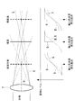
- FIG. 1 is a block diagram illustrating an image processing apparatus according to an embodiment of the present invention. It is a figure which shows typically the relationship between the optical system to which the image processing apparatus of FIG. 1 is applied, and axial chromatic aberration. It is a figure which shows typically the relationship between the optical system to which the image processing apparatus of FIG. 1 is applied, and axial chromatic aberration.
- 2 is a flowchart illustrating an image processing method using the image processing apparatus of FIG. 1. It is a figure which shows the coordinate relationship of the attention pixel set in the image processing apparatus of FIG. 1, and its peripheral pixel. It is a figure which shows the coordinate relationship of the attention pixel set in the image processing apparatus of FIG.
- FIG. 2 is a diagram illustrating a coordinate relationship between a target pixel set in the image processing apparatus of FIG. 1 and its surrounding pixels, and in particular, a target pixel before correction when the pixel position of the target pixel is determined as a D1 direction and the pixel The coordinate relationship with surrounding pixels is shown.
- FIG. 2 is a diagram illustrating a coordinate relationship between a target pixel set in the image processing apparatus of FIG.
- the image processing apparatus performs image processing to be described later on an input image acquired by a camera.
- the input image that is the processing target of the image processing apparatus 1 is converted into an electrical signal in the solid-state imaging device after the light beam that has entered through the imaging optical system (not shown) is subjected to fixed noise pattern removal, analog gain adjustment, and the like.
- the image signal is converted into a digital signal by an A / D converter and subjected to various image processing.
- This input image is a full-color image in which all RGB signal values are obtained at each pixel, and a three-plate color image acquired by a three-plate image sensor or a single-plate color image acquired by a single-plate image sensor at each pixel. It is an image that has been interpolated to obtain RGB values.
- the image processing apparatus includes an area extraction unit 2 that extracts an axial chromatic aberration region in which an axial chromatic aberration occurs in an input image, and an axis extracted by the region extraction unit 2.
- An axial chromatic aberration correction amount calculation unit 3 that calculates a correction amount for the upper chromatic aberration region and an aberration correction unit 4 that outputs an output image in which the axial chromatic aberration in the axial chromatic aberration region is corrected are provided.
- the region extraction unit 2 includes a total pixel value calculation unit 10, a generation start point detection unit 11, and a region determination unit 12.
- the total pixel value calculation unit 10 sets a target pixel in the input image, and for a plurality of pixels arranged in a line including the set target pixel, the one direction (D1) and the other direction centering on the target pixel
- the pixel values of the pixels arranged in (D2) are summed for each color.
- the occurrence starting point detection unit 11 includes at least a pixel value of the target pixel, or a total pixel value of pixels arranged in one direction across the target pixel calculated by the total pixel value calculation unit 11 or a total pixel value of pixels arranged in the other direction. On the basis of one of them, it is determined whether the pixel of interest is the origin of axial chromatic aberration, and the pixel of interest that is the origin of occurrence is detected.
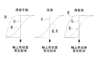
- the generation start point of the longitudinal chromatic aberration detected by the generation start point detection unit 5 is, for example, a target pixel in which the magnitude of the G pixel value of the target pixel becomes a saturation level, or as shown in FIG.
- a long wavelength R with respect to G forms an image on the far side in the optical axis direction
- a short wavelength B with respect to G forms an image on the near side in the optical axis direction.
- This RGB imaging position shift appears as axial chromatic aberration.
- G When an achromatic step edge is photographed, G has a step edge shape on the image plane, but R and B do not form an image and the step edge shape is dull.
- G In the back of the image plane, G does not form an image, so the shape of the step edge is dull, but R forms an image and maintains the shape of the step edge.
- B is duller than G.
- G In front of the image plane, G does not form an image, so the shape of the step edge is dull, and B forms an image and maintains the shape of the step edge.
- R has a shape duller than G.
- the region determination unit 12 determines a predetermined peripheral region of the target pixel that is the generation start point detected by the generation start point detection unit 5 as an axial chromatic aberration region. That is, when the pixel of interest is detected as the origin of axial chromatic aberration, the pixel is subject to correction of axial chromatic aberration. Therefore, the region consisting of the pixel of interest and a predetermined peripheral pixel centered on the pixel of interest is the axial chromatic aberration region.
- the axial chromatic aberration region can be set as appropriate, for example, a 5 ⁇ 5 pixel region centered on the pixel of interest or a 7 ⁇ 7 pixel region.
- the axial chromatic aberration correction amount calculation unit 3 includes a color space information calculation unit 15, a color space difference calculation unit 16, and a correction amount calculation unit 17.
- the color space information calculation unit 15 calculates the color space information on the specific color space for the target pixel detected as the generation start point by the generation start point detection unit 5 for each of the one direction and the other direction with respect to the target pixel.
- the specific color space for example, HSV space or l * a * b space can be applied.
- the color space information is the sum of pixel values for each color for pixels arranged in one direction (D1) and the other direction (D2) around the target pixel, calculated by the total pixel value calculation unit 10. Calculate based on
- the color space difference calculation unit 16 calculates a difference between the color space information in one direction calculated by the color space information calculation unit 15 and the color space information in the other direction.
- the correction amount calculation unit 17 calculates a correction amount for the axial chromatic aberration region according to the difference calculated by the color space difference calculation unit 16.
- the aberration correction unit 4 corrects the axial chromatic aberration region using the correction amount calculated by the correction amount calculation unit 17.
- step S1 the total pixel value calculation unit 10 sets a target pixel (0, 0) in the input image as shown in FIG. 5, and in the next step S2 (total pixel value calculation step), the target pixel 5, the sum of pixel values of a plurality of pixels arranged on both sides of the pixel of interest is calculated in each of the four directions of the vertical direction, the horizontal direction, the right diagonal direction, and the left diagonal direction in FIG. 5 (step S2). Specifically, the sum of pixel values for each color in each direction is calculated according to the equation shown in Equation 1.
- P c (x, y) is the pixel value of the pixel located at the coordinates (x, y)
- P cL is the sum of the pixel values of the pixel column on the left side of the target pixel
- P cR is the right side of the target pixel.
- the total pixel value of the pixel column P cT is the total pixel value of the upper pixel column of the target pixel
- P cB is the total pixel value of the lower pixel column of the target pixel
- P cLT is the upper left side of the target pixel.
- P cLB is the total pixel value of the pixel column on the lower left side of the target pixel
- P cRT is the total pixel value of the pixel column on the upper right side of the target pixel
- P cRB is the lower right side of the target pixel This is the sum of the pixel values of the side pixel column.
- the subscript c means color and can be replaced with r, g, and b, and the total of pixel values for each color is calculated by replacement. I and m are positive integers.
- step S3 occurrence start point detection step
- the occurrence start point detection unit 11 determines that the following conditional expression (1) or the sum of the pixel values calculated by the total pixel value calculation part 10 is conditional expressions (2) to (5).
- conditional expression (1) indicates that when the magnitude of the G pixel value of the pixel of interest is larger than an arbitrary saturation level threshold THsat, the pixel of interest is detected as an origin of axial chromatic aberration.
- Pg D1 is the sum of G pixel values of pixels arranged in one direction D1 from the target pixel
- Pg D2 is the sum of G pixel values of pixels arranged in the other direction D2 from the target pixel
- Pr D1 is the sum of R pixel values of pixels arranged in one direction D1 from the target pixel
- Pr D2 is the sum of R pixel values of pixels arranged in the other direction D2 from the target pixel
- Pb D1 is the target pixel
- Pb D2 is the total of the B pixel values of the pixels arranged in the other direction D2 from the target pixel.
- the subscript D1 indicates one direction from the target pixel, and for example, L, T, LT, and LB in Equation 1 are applicable. Further, the subscript D2 indicates the other direction from the target pixel, and for example, R, B, RT, and RB are applicable. The definition of the direction is arbitrary, but when L, T, LT, and LB are selected as D1, D2 becomes R, B, RT, and RB.
- conditional expression (1) when comparing the target pixel with the arbitrary saturation level threshold THsat, only the G pixel of the target pixel is used.
- the saturation level threshold value and the luminance value can be compared, and other known methods can be used.
- the method for calculating the origin of axial chromatic aberration in a region other than near-saturation is not limited to the above example, and a known method can be used.
- step S4 detection information generation step
- the generation start point detection unit 11 sets “0” for the pixel of interest detected as the generation start point of axial chromatic aberration, and “1” for the pixel detected as not the generation start point. Detection information to be generated.
- the generation start point detection unit 11 holds PrD1, PrD2, PgD1, PgD2, PbD1, and PbD2 corresponding to the pixel position.
- the four directions of the vertical direction, horizontal direction, right diagonal direction, and left diagonal direction in FIG. 5 are associated with the pixel position. Which direction satisfies the conditional expressions (2) to (5), and holds the one direction D1 and the other direction D2 with respect to that direction. That is, the occurrence start point detection unit 11 holds whether D1 is L, T, LT, or LB and D2 is R, B, RT, or RB as information related to the detection information. Keep it.
- step S ⁇ b> 5 region determination step
- the region determination unit 12 detects that the target pixel is the generation start point of axial chromatic aberration, that is, the detection information generated by the generation start point detection unit 11 for the target pixel is “ In the case of “0”, the region including the target pixel and the predetermined peripheral pixel is determined as the axial chromatic aberration region.
- the axial chromatic aberration region for example, a region including 7 ⁇ 7 pixels centered on a pixel whose detection information is “0” can be set as appropriate.
- step S6 color space information calculation step
- the color space information calculation unit 15 determines the color of the specific color space from PrD1, PgD1, PbD1 and PrD2, PgD2, PbD2 corresponding to the pixel position where the detection information is “0”. Calculate spatial information. For example, when the specific color space is HSV space, at least one of PrD1, PgD1, and PbD1 to PhD1, PsD1, and PvD1 is calculated, and PrD2, PgD2, and PbD2 to PhD2, PsD2, and PvD2 are calculated in the same color space information. To do.
- PhD1 and PhD2 indicate color space information regarding angles (hues) in the D1 direction and D2 direction of the target pixel detected as the generation start point
- PsD1 and PsD2 indicate the target detection detected as the generation start point.
- the color space information regarding the intensity (saturation) in the D1 direction and the D2 direction in the pixel is shown
- PvD1 and PvD2 are related to the brightness (brightness) in the D1 direction and the D2 direction in the target pixel detected as the generation start point. Indicates color space information.
- the specific color space is L * a * b * space
- at least one of PrD1, PgD1, PbD1 to Pl * D1, Pa * D1, Pb * D1, PrD2, PgD2, PbD2 to Pl * D2, Pa * The same color space information as the direction D1 of D2 and Pb * D2 is calculated.
- Pl * D1 and Pl * D2 indicate color space information regarding brightness (brightness) in the D1 direction and D2 direction at the target pixel detected as the generation start point
- Pa * D1, Pb * D1, Pa * D2 and Pb * D2 are information regarding complementary colors, and can be used as color space information regarding angle and intensity.
- step S7 color space difference calculation step
- the color space difference calculation unit 16 calculates a difference in color space from the color space information in two directions.
- the color section information calculation unit 16 calculates at least one of a color angle difference, a color intensity difference, and a brightness difference as a difference.
- step S8 correction amount calculation step
- a correction amount is calculated based on the difference calculated by the color space difference calculation unit 16.
- step S9 it is determined whether or not all pixels have been processed. If the process for the pixel is not completed, the process returns to step S1, and the process of steps S2 to S7 is repeated with the pixel that has not been processed yet as the target pixel.
- the correction amount calculated by the correction amount calculation unit 17 is used for the axial chromatic aberration region set by the region determination unit 12 in step S10 (aberration correction step).
- a correction process is performed by the aberration correction unit 4 and the process ends.
- At least one of an angle, an intensity, and a brightness is calculated as color space information, and at least one of an angle difference, an intensity difference, and a brightness difference is calculated from the color space information.
- a correction amount is calculated based on information obtained by combining any one or more of these differences, thereby correcting the axial chromatic aberration region.
- the correction amount is calculated by combining any one or more of the difference in angle, the difference in intensity, and the difference in brightness
- the color space angle information calculation unit 15 calculates the color space information related to the angles for the two directions (D1, D2) held as information related to the detection information by the generation start point detection unit 11 (step S6).
- the color space angle difference calculation unit 16 calculates the difference from the color space information regarding the calculated angle (step S7).
- the generation start point detection unit 11 determines that the target pixel is the generation start point by satisfying the conditional expression (1)
- the size of the G pixel value of the target pixel is greater than an arbitrary saturation level threshold THsat.
- the D1 and D2 in a specific direction are not determined.
- the Pangle is calculated for D1 and D2 in all four directions in the vertical, horizontal, and diagonal directions, and the value with the largest Pangle can be adopted.
- the correction amount calculation unit 17 calculates the correction amount Ca from the Pangle. For example, when the Pangle is a value from 0 to 360 degrees, the correction amount Ca is increased as the Pangle is closer to 180 degrees, and the correction amount is decreased as the Pangle is farther from 180 degrees.
- the angle of the color space is expressed from 0 degrees to 360 degrees as in a hue circle, an appropriate correction amount when coloration is easy to be detected by humans, such as 180 degrees where two colors are counter electrodes Can be calculated.
- the correction amount so that the color angle is the same in one direction and the other direction, there is no difference in the color angle after correction, and it is possible to calculate a desired correction amount for human coloring. .
- the correction processing of the aberration correction unit based on the correction amount calculated from the color space information regarding the angle for example, sets the pixel value before correction to Pr as shown in FIG. , Pg, Pb, and corrected pixel values as Pr ′, Pg ′, Pb ′ as shown in FIG. 7 are performed according to the following equations (8) to (10).
- Pr ' Pr-Ca (8)
- Pg ' Pg (9)
- Pb ' Pb-Ca (10)
- correction can be performed according to the following equation (11), where Pa is the angle of the pixel value before correction, and Pa ′ is the angle of the pixel value after correction.
- Pa ' Pa-Ca (11)
- the color space information calculation unit 15 calculates Pangle 1 and Pangle 2 as the color space information regarding the angle according to the following Expressions (12) and (13).
- Pangle1 PhD1 (12)
- Pangle2 PhD2 (13)
- Pangle 1 and Pangle 2 are calculated according to the following formulas (14) and (15) as the color space information regarding the angle.
- Pangle1 tan-1 (Pb * D1 / Pa * D1)
- Pangle2 tan-1 (Pb * D2 / Pa * D2)
- the color space information calculation unit 15 calculates, for example, Pangle 1 and Pangle 2 using D1 and D2 in all the four directions, ie, the vertical, horizontal, and diagonal directions, and the color space difference calculation unit 16
- the maximum absolute value of the difference between the two and the Pangle 2 is adopted as the difference of the color space information regarding the angle, and D1 and D2 indicating the maximum absolute value can be set as the specific direction.
- the absolute value Pangle of the difference in the color space information related to the angle is calculated by Expression (16).
- the correction amount calculation unit 17 calculates the correction amounts Ca1 and Ca2 from the Pangle, Pangle1, and Pangle2, for example, according to the following equations (17) to (20).
- Pangle1 is larger than Pangle2
- Ca1 Pangle (17)
- Ca2 0 (18)
- Ca2 Pangle (20)
- the aberration correction unit 4 performs correction processing on the axial chromatic aberration region using the correction amount based on the angle calculated by the correction amount calculation unit 17.
- the correction processing based on the angle by the aberration correction unit 4 uses Pr1, Pg1, Pb1 (FIG. 8) as pixel values before correction, and after correction.
- the pixel values can be expressed by the following equations (21) to (23) with Pr1 ′, Pg1 ′, and Pb1 ′ (FIG. 9).
- Pr1 ' Pr-Ca1 (21)
- Pg1 ' Pg (22)
- Pb1 ' Pb-Ca1 (23)
- correction processing can be performed by the following equation (28), where the angle of the pixel value before correction is Pangle 2 and the angle of the pixel value after correction is Pagle 2 ′.
- Pangle2 ' Pangle2-Ca2 (28)
- the color space angle information calculation unit 15 calculates the color space information related to the intensity for each of the two directions (D1, D2) held as information related to the detection information by the generation start point detection unit 11 (step S6).
- the color space angle difference calculation unit 16 calculates the difference from the color space information regarding the calculated intensity (step S7). Specifically, when the specific color space is an HSV space, PsD1 and PsD2 are calculated as color space information regarding intensity, and an absolute value Pstrength of these differences is calculated according to the following equation (29).
- Pstrength
- Pstrength
- the generation start point detection unit 11 determines that the target pixel is the generation start point by satisfying the conditional expression (1) and the D1 and D2 in the specific direction are not determined, for example, the above-described vertical, horizontal, and diagonal totals are used.
- Pstrength can be calculated from D1 and D2 in all four directions, the maximum value of Pstrength can be adopted, and D1 and D2 indicating the maximum value can be set as a specific direction.
- the correction amount calculation unit 17 calculates the correction amount Cb from Pstrength according to the following equation (31).
- K is an arbitrary constant.
- Cb K * Pstrength (31)
- the aberration correction unit 4 performs correction processing on the axial chromatic aberration region using the correction amount based on the intensity calculated by the correction amount calculation unit.
- correction processing can be performed according to the following equation (35), where Ps is the intensity of the pixel value before correction and Ps ′ is the intensity of the pixel value after correction.
- Ps' Ps-Cb (35)
- the color space information calculation unit 15 calculates Pstrength1 and Pstrength2 as the color space information regarding the intensity according to the following expressions (36) and (37).
- Pstrength1 PsD1 ... (36)
- Pstrength2 PsD2 (37)
- Pstrength1 and Pstrength2 are calculated according to the following equations (38) and (39) as the color space information regarding the intensity.
- Pstrength1 ⁇ (Pa * D1 ⁇ 2 + Pb * D1 ⁇ 2) (38)
- Pstrength2 ⁇ (Pa * D2 ⁇ 2 + Pb * D2 ⁇ 2)... (39)
- the color space information calculation unit 15 performs the above-described process.
- Pstrength1 and Pstrength2 are calculated from D1 and D2 in all four directions, vertical, horizontal, and diagonal, and the color space difference calculation unit 16 calculates the absolute value of the difference between Pstrength1 and Pstrength2 in the color space information regarding the intensity Adopted as a difference, D1 and D2 indicating the maximum absolute value can be set as a specific direction.
- the absolute value Pstrength of the difference in the color space information regarding the intensity is calculated by the following equation (40).
- the correction amount calculation unit 17 calculates correction amounts Cb1 and Cb2 from Pstrength, Pstrength1, and Pstrength2, for example, according to the following equations (41) to (44).
- Pstrength1 is greater than Pstrength2
- Cb1 Pstrength (41)
- Cb2 0 ...
- Cb2 Pstrength (44)
- the aberration correction unit 4 performs correction processing on the axial chromatic aberration region using the correction amount based on the intensity calculated by the correction amount calculation unit 17.
- the correction values based on the intensity by the aberration correction unit 17 are the pixel values before correction Pr1, Pg1, Pb1 (FIG. 8), and after correction.
- the pixel values are represented by Pr1 ′, Pg1 ′, Pb1 ′ (FIG. 9) and can be expressed by the following equations (45) to (47).
- Pr1 ' Pr-Cb1 (45)
- Pg1 ' Pg (46)
- Pb1 ' Pb-Cb1 (47)
- the correction processing can be performed by the following equation (52), where the intensity of the pixel value before correction is Pstrength2 and the intensity of the pixel value after correction is Pstrength2 ′.
- Pstrength2 ' Pstrength2-Cb2 (52)
- the color space angle information calculation unit 15 calculates color space information related to brightness for each of the two directions (D1, D2) held by the generation start point detection unit 11 as information related to the detection information (step S6). .
- the color space angle difference calculation unit 16 calculates the difference from the color space information regarding the calculated brightness (step S7).
- PvD1 and PvD2 are calculated as color space information regarding brightness, and an absolute value Plightness of these differences is calculated according to the following equation (53).
- Plightness
- the generation start point detection unit 11 determines that the target pixel is the generation start point by satisfying the conditional expression (1) and the D1 and D2 in the specific direction are not determined, for example, the above-described vertical, horizontal, and diagonal totals are used. It is possible to calculate Plightness with D1 and D2 in all four directions, adopt the maximum value of Plightness, and set D1 and D2 indicating the maximum values as specific directions.
- the correction amount calculation unit 17 calculates the correction amount Cc from Plightness according to the following equation.
- K is an arbitrary constant.
- Cc K * Plightness (55)
- the aberration correction unit 4 performs correction processing on the axial chromatic aberration region using the correction amount based on the brightness calculated by the correction amount calculation unit.
- the correction processing of the aberration correction unit can be expressed by the following equations (56) to (58) with the corrected pixel values as Pr ′, Pg ′, and Pb ′.
- Pr ' Pr-Cc (56)
- Pg ' Pg (57)
- Pb ' Pb-Cc (58)
- the color space information calculation unit 15 calculates Plightness 1 and Plightness 2 as color space information regarding brightness according to the following formulas (60) and (61).
- Plightness1 PvD1 (60)
- Plightness2 PvD2 (61)
- Plightness 1 and Plightness 2 are calculated according to the following equations (62) and (63) as color space information regarding brightness.
- Plightness1 Pl * D1 (62)
- Plightnss2 Pl * D2 (63)
- the color space information calculation unit 15 performs the above-described process.
- the color space difference calculation unit 16 calculates the maximum absolute value of the difference between Plightness 1 and Plightness 2 by using D1 and D2 in all four directions, ie, vertical, horizontal, and diagonal. D1 and D2 indicating the maximum absolute value can be set as the specific direction.
- the correction amount calculation unit 17 calculates correction amounts Cc1 and Cc2 from Plightness, Plightness1, and Plightness2 according to, for example, the following equations (65) to (68).
- Plightness 1 is greater than Plightness 2
- Cc1 Plightness (65)
- Cc2 0 ...
- Plightness2 is greater than Plightness1
- Cc2 Plightness (68)
- the aberration correction unit 4 performs correction processing on the axial chromatic aberration region using the correction amount based on the brightness calculated by the correction amount calculation unit 17.
- the pixel values before correction are Pr1, Pg1, Pb1 (FIG. 8)
- the correction processing based on the brightness by the aberration correction unit 17 is performed.
- Pr1 ' Pr-Cc1 (69)
- Pg1 ' Pg (70)
- Pb1 ' Pb-Cc1 (71)
- the brightness of the pixel value before correction is Plightness 1
- the intensity of the pixel value after correction is Plightness 1 ′
- correction processing can be performed according to the following equation (72).
- Plightness1 ' Plightness1-Cc1 (72)
- the correction process can be performed.
- Pr2 ' Pr-Cc2 (73)
- Pg2 ' Pg (74)
- Pb2 ' Pb-Cc2 (75)
- the correction processing can be performed by the following equation (76), where the brightness of the pixel value before correction is Plightness 2 and the intensity of the pixel value after correction is Plightness 2 ′.
- Plightness2 ' Plightness2-Cc2 (76)
- the color space angle information calculation unit 15 calculates the color space information regarding the angle and the intensity for each of the two directions (D1, D2) held as information related to the detection information by the generation start point detection unit 11 (step S6). ).
- the color space angle difference calculation unit 16 calculates these differences from the color space information regarding the calculated angle and intensity (step S7).
- the aberration correction unit 4 performs correction processing on the axial chromatic aberration region using the correction amount Cab based on the angle and intensity calculated by the correction amount calculation unit 17.
- the correction processing of the aberration correction unit 4 is as follows.
- the pixel values before correction are Pr, Pg, Pb, and the pixel values after correction are Pr ′, Pg ′, Pb ′ as shown in FIG. This is performed according to the equations (78) to (80).
- Pr ' Pr-Cab (78)
- Pg ' Pg (79)
- Pb ' Pb-Cab (80)
- the correction amount calculation unit 17 calculates the correction amounts Ca1, Ca2 and Cb1, Cb2 according to, for example, the equations (17) to (20), and uses these to calculate the correction amounts Cab1, Cab2 based on the angle and intensity, for example, It can be calculated according to equations (83) and (84).
- the calculation method is as follows.
- Cab1 Ca1 + Cb1 (83)
- Cab2 Ca1 + Cb2 (84)
- the aberration correction unit 4 performs correction processing on the axial chromatic aberration region using the correction amount based on the angle calculated by the correction amount calculation unit 17.
- the correction processing based on the angle by the aberration correction unit 17 uses Pr1, Pg1, Pb1 (FIG. 8) as pixel values before correction, and after correction.
- the pixel values can be expressed by the following equations (85) to (87) with Pr1 ′, Pg1 ′, and Pb1 ′ (FIG. 9).
- Pr1 ' Pr-Cab1 (85)
- Pg1 ' Pg (86)
- Pb1 ' Pb-Cab1 (87)
- the correction process can be performed.
- Pr2 ' Pr-Cab2 (90)
- Pg2 ' Pg (91)
- Pb2 ' Pb-Cab2 (92)
- the correction processing can be performed by the following equation (93), where the angle of the pixel value before correction is Pangle 2 and the angle of the pixel value after correction is Pangle 2 ′.
- Pangle2 ' Pangle2-Cb2 (93)
- the correction processing can be performed by the following equation (94), where the intensity of the pixel value before correction is Pstrength2 and the intensity of the pixel value after correction is Pstrength2 ′.
- Pstrength2 ' Pstrength2-Cb2 (94)
- the color space angle information calculation unit 15 calculates the color space information regarding the angle and the brightness for each of the two directions (D1, D2) held as information related to the detection information by the generation start point detection unit 11 (step S1). S6).
- the color space angle difference calculation unit 16 calculates these differences from the color space information regarding the calculated angle and brightness (step S7).
- the correction amount Cac based on the angle and the brightness is calculated according to the following formula (95), for example.
- Cac Ca + Cc (95)
- the aberration correction unit 4 performs correction processing on the axial chromatic aberration region using the correction amount Cab based on the angle and intensity calculated by the correction amount calculation unit 17.
- the correction processing of the aberration correction unit 4 is as follows.
- the pixel values before correction are Pr, Pg, Pb, and the pixel values after correction are Pr ′, Pg ′, Pb ′ as shown in FIG. This is performed according to the equations (78) to (80).
- Pr ' Pr-Cac (96)
- Pg ' Pg (97)
- Pb ' Pb-Cac (98)
- correction can be performed according to the following equation (99), where Pa is the angle of the pixel value before correction and Pa ′ is the angle of the pixel value after correction.
- Pa ' Pa-Ca (99)
- Pl ' Pl-Cc (100)
- the correction amount calculation unit 17 calculates the correction amounts Ca1 and Ca2 based on the angle and the correction amounts Cc1 and Cc2 based on the brightness, and uses these to calculate the correction amounts Cac1 and Cac2 based on the angle and the brightness, for example, as follows: It can be calculated according to the formula.
- Cac1 Ca1 + Cc1 (101)
- Cac2 Ca2 + Cc2 (102)
- the aberration correction unit 4 performs correction processing on the axial chromatic aberration region using the correction amount based on the angle calculated by the correction amount calculation unit 17.
- the correction processing based on the angle by the aberration correction unit 17 uses Pr1, Pg1, Pb1 (FIG. 8) as pixel values before correction, and after correction.
- the pixel values can be expressed by the following equations (103) to (105) with Pr1 ′, Pg1 ′, and Pb1 ′ (FIG. 9).
- Pr1 ' Pr-Cac1 (103)
- Pg1 ' Pg (104)
- Pb1 ' Pb- Cac1 (105)
- the correction may be performed by the following equation.
- Plightness1 ' Plightness1-Cc1 (107)
- correction processing can be performed according to the following equation (111).
- Pangle2 ' Pangle2-Cb2 (111)
- the correction process can be performed according to the following equation (112).
- Plightness2 ' Plightness2-Cc2 (112)
- the color space angle information calculation unit 15 calculates color space information regarding intensity and brightness for each of the two directions (D1, D2) held as information related to the detection information by the generation start point detection unit 11 (step S1). S6).
- the color space angle difference calculation unit 16 calculates these differences from the color space information related to the calculated intensity and brightness (step S7).
- the correction amount Cbc based on the intensity and the brightness is calculated according to the following formula (95), for example.
- Cbc Cb + Cc (113)
- the aberration correction unit 4 performs correction processing on the axial chromatic aberration region using the correction amount Cab based on the angle and intensity calculated by the correction amount calculation unit 17.
- the correction processing of the aberration correction unit 4 is as follows.
- the pixel values before correction are Pr, Pg, Pb, and the pixel values after correction are Pr ′, Pg ′, Pb ′ as shown in FIG. This is performed according to equations (114) to (116).
- Pr ' Pr-Cbc (114)
- Pg ' Pg (115)
- Pb ' Pb-Cbc (116)
- the correction can also be performed according to the following equation (117), where Ps is the intensity of the pixel value before correction and Ps ′ is the intensity of the pixel value after correction.
- Ps' Ps-Cb (117)
- Pl ' Pl-Cc (118)
- the correction amount calculation unit 17 calculates the correction amounts Cb1 and Cb2 based on the intensity and the correction amounts Cc1 and Cc2 based on the brightness, and uses these to calculate the correction amounts Cbc1 and Cbc2 based on the intensity and the brightness, for example, Calculate according to (119) and (120).
- Cbc1 Cb1 + Cc1 (119)
- Cbc2 Cb2 + Cc2 (120)
- the aberration correction unit 4 performs correction processing on the axial chromatic aberration region using the correction amount based on the angle calculated by the correction amount calculation unit 17.
- the correction processing based on the angle by the aberration correction unit 17 uses Pr1, Pg1, Pb1 (FIG. 8) as pixel values before correction, and after correction.
- the pixel values can be expressed by the following equations (121) to (123) with Pr1 ′, Pg1 ′, and Pb1 ′ (FIG. 9).
- Pr1 ' Pr-Cbc1 (121)
- Pg1 ' Pg (122)
- Pb1 ' Pb-Cbc1 (123)
- correction processing can be performed according to the following equation (124), assuming that the intensity of the pixel value before correction is Pstrength1 and the intensity of the pixel value after correction is Pstrength1 ′.
- Pstrength1 ' Pstrength1-Cb1 (124)
- the brightness of the pixel value before correction is Plightness 1
- the intensity of the pixel value after correction is Plightness 1 ′
- correction processing can be performed according to the following equation (125).
- Plightness1 ' Plightness1-Cc1 (125)
- the intensity of the pixel value before correction is Pstrength2 and the intensity of the pixel value after correction is Pstrength2 ′
- correction processing can be performed according to the following equation (129).
- Pstrength2 ' Pstrength2-Cb2 (129)
- the correction process can be performed according to the following equation (130).
- Plightness2 ' Plightness2-Cc2 (130)
- the color space angle information calculation unit 15 calculates color space information related to the angle, intensity, and brightness for each of the two directions (D1, D2) that the generation start point detection unit 11 holds as information related to the detection information. (Step S6).
- the color space angle difference calculation unit 16 calculates these differences from the color space information related to the calculated angle, intensity, and brightness (step S7).
- the aberration correction unit 4 performs correction processing on the axial chromatic aberration region using the correction amount Cab based on the angle and intensity calculated by the correction amount calculation unit 17.
- the correction processing of the aberration correction unit 4 is as follows.
- the pixel values before correction are Pr, Pg, Pb, and the pixel values after correction are Pr ′, Pg ′, Pb ′ as shown in FIG. This is performed according to equations (132) to (134).
- Pr ' Pr-Cabc (132)
- Pg ' Pg (133)
- Pb ' Pb-Cabc (134)
- correction can be performed according to the following equation (135), where Pa is the angle of the pixel value before correction, and Pa ′ is the intensity of the pixel value after correction.
- Pa ' Pa-Ca (135)
- Ps' Ps-Cb (136)
- correction according to the following equation (137) assuming that the brightness of the pixel value before correction is Pl and the intensity of the pixel value after correction is Pl ′.
- Pl ' Pl-Cc (137)
- Cabc1 based on angle, intensity, and brightness using correction amounts Ca1 and Ca2 based on brightness, correction amounts Cb1 and Cb2 based on intensity, and correction amounts Cc1 and Cc2 based on brightness calculated by the correction amount calculation unit 17 , Cabc2 is calculated according to, for example, the following equations (138) and (139).
- Cabc1 Ca1 + Cb1 + Cc1 (138)
- Cabc2 Ca2 + Cb2 + Cc2 (139)
- the aberration correction unit 4 performs correction processing on the axial chromatic aberration region using the correction amount based on the angle calculated by the correction amount calculation unit 17.
- the correction processing based on the angle by the aberration correction unit 17 uses Pr1, Pg1, Pb1 (FIG. 8) as pixel values before correction, and after correction.
- Pixel values are represented by Pr1 ′, Pg1 ′, Pb1 ′ (FIG. 9) and can be expressed by the following equations (140) to (142).
- Pr1 ' Pr-Cabc1 (140)
- Pg1 ' Pg (141)
- Pb1 ' Pb-Cabc1 (142)
- the brightness of the pixel value before correction is Plightness 1
- the intensity of the pixel value after correction is Plightness 1 ′
- correction processing can be performed according to the following equation (145).
- Plightness1 ' Plightness1-Cc1 (145)
- the correction process can be performed according to the following equation (151).
- Plightness2 ' Plightness2-Cc2 (151)
- axial chromatic aberration is detected in at least one of the near-saturated region or the region other than the near-saturated region, and the human Corrections can be made based on visual characteristics.
- the axial chromatic aberration is generated when all the conditional expressions (2) to (5) described above are satisfied. 10 and 11, when the conditional expression (2) and the conditional expression (3) are satisfied, or when the conditional expression (4) and the conditional expression (5) are satisfied, the target pixel is placed on the axis. It may be detected that the chromatic aberration is generated. By doing so, there is an advantage that the origin of axial chromatic aberration can be detected in a depth range wider than the focus position.
- the pixel of interest is the origin of occurrence of axial chromatic aberration. You may detect as. By doing so, purple fringes occur in the other direction D2, and the sum of the R pixel values or the sum of the B pixel values in the one direction D1 is smaller than the sum of the G pixel values. It is possible to detect the place where the purple fringe is conspicuous with a color close to 2 as the starting point of the longitudinal chromatic aberration.
- the attention pixel is set as the origin of occurrence of axial chromatic aberration. You may detect as. By doing so, a green fringe occurs in one direction D1, the sum of R pixel values or the sum of B pixel values in the other direction D2 is larger than the sum of G pixel values, and an opposite color is displayed in the hue circle. The position where the green fringe becomes conspicuous with a color close to is detectable as the origin of the longitudinal chromatic aberration.
- the target pixel may be detected as a starting point of axial chromatic aberration.
- Pg D2 -TH R2 ⁇ Pr D2 (153)
- Pg D1 + TH B1 > Pb D1 154)
- Pg D2 -TH B2 ⁇ Pb D2 155)
- TH R1 , TH R2 , TH B1 and TH B2 are arbitrary constants.
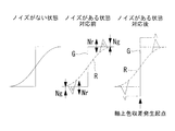
- TH R1 , TH R2 , TH B1 , and TH B2 for example, as shown in FIG. 12, for example, a difference between standard deviations indicating noise amounts of G and R or G and B at a pixel position to be processed is illustrated. be able to.
- the R, G, and B noise amounts in one direction D1 and the other direction D2 are expressed by the following formulas (156) to (159) as Nr D1 , Ng D1 , Nb D1 , Nr D2 , Ng D2 , and Nb D2 , respectively. be able to.
- TH R1 Nr D1 -Ng D1 (156)
- TH R2 Nr D2 -Ng D2
- TH B1 Nb D1 -Ng D1 (158)
- TH B2 Nb D2 -Ng D2 (159)
- the target pixel may be detected as a starting point of axial chromatic aberration.
- TH R and TH B are arbitrary constants.
- TH R and TH B As the constants TH R and TH B, as shown in FIG. 13, for example, a difference between G and R or G and B pixel values at a pixel position to be processed can be exemplified.
- the pixel values of R, G, and B of the pixel of interest are Pr (0, 0), Pg (0, 0), and Pb (0, 0)
- the following equations (164) and (165) are obtained.
- TH R Pg (0,0)-Pr (0,0) (164)
- TH B Pg (0,0)-Pb (0,0) (165)
- the target pixel may be detected as an origin of axial chromatic aberration.
- K R, K B is an arbitrary constant.
- K R and K B the ratio of G and R or G and B pixel values at the pixel position to be processed can be exemplified.
- the pixel values of R, G, and B of the pixel of interest are Pr (0, 0), Pg (0, 0), and Pb (0, 0)
- the following expressions (170) and (171) are obtained.
- K R Pg (0,0) / Pr (0,0) (170)
- K B Pg (0,0) / Pb (0,0) (171)
- This also has the advantage that it is possible to detect the origin of axial chromatic aberration that occurs on a colored subject, not an achromatic color.
- the total pixel value is calculated by the mathematical formulas shown in Equations 2 and 3.
- the total pixel value is calculated by the mathematical formulas shown in Equation 4 and Equation 5.
- the total pixel value is calculated by the mathematical formulas shown in Equation 6 and Equation 7.
- the total pixel value is calculated by the mathematical formulas shown in Formula 8 and Formula 9.
- the image processing apparatus 1 is used by being mounted on a product such as a stationary broadcast camera, an ENG camera, a consumer handy camera, or a digital camera. It can also be used in an image signal correction program (CG program), an image editing apparatus, etc. that handle moving images.
- CG program image signal correction program
- the image processing method according to the present embodiment can also be used as an image processing program that causes a computer (for example, a personal computer) to execute the image processing method.
Landscapes
- Engineering & Computer Science (AREA)
- Multimedia (AREA)
- Signal Processing (AREA)
- Physics & Mathematics (AREA)
- Spectroscopy & Molecular Physics (AREA)
- Image Processing (AREA)
- Color Television Image Signal Generators (AREA)
Abstract
On décrit un dispositif de traitement d'images qui comprend: une unité de calcul de valeur de pixel totale (10) destinée à totaliser, pour chaque couleur, les valeurs de pixel de pixels alignés dans une direction et dans une autre direction avec un pixel d'intérêt, parmi des pixels alignés en une rangée, en tant que centre; une unité de détection de point de départ d'occurrence (11) pour déterminer, sur la base du résultat du calcul effectuée par l'unité de calcul de valeur de pixel totale et/ou de la valeur de pixel du pixel d'intérêt, si le pixel d'intérêt est le point de départ d'occurrence pour une aberration chromatique axiale, et détecter le point de départ d'occurrence; une unité de détermination de zone (12) pour déterminer qu'une zone environnante prédéfinie comportant le point de départ d'occurrence comme centre est bien la zone d'aberration chromatique axiale; une unité de calcul d'informations d'espace chromatique (15) pour calculer les informations d'espace chromatique pour un espace chromatique spécifié, dans l'une et l'autre direction, sur la base du résultat de calcul de l'unité de calcul de valeur de pixel totale pour le point de départ d'occurrence; une unité de calcul de différence d'espace chromatique (16) pour calculer la différence entre les informations d'espace chromatique pour ladite une direction et les informations d'espace chromatique pour ladite autre direction; une unité de calcul de valeur de correction (17) pour calculer la valeur de correction de l'aberration chromatique axiale selon la différence; et une unité de correction (4) pour corriger la zone d'aberration chromatique axiale en utilisant la valeur de correction.
Priority Applications (4)
| Application Number | Priority Date | Filing Date | Title |
|---|---|---|---|
| CN201580079861.6A CN107534758B (zh) | 2015-05-12 | 2015-05-12 | 图像处理装置、图像处理方法和记录介质 |
| JP2017517499A JP6633624B2 (ja) | 2015-05-12 | 2015-05-12 | 画像処理装置、画像処理方法及び画像処理プログラム |
| PCT/JP2015/063540 WO2016181476A1 (fr) | 2015-05-12 | 2015-05-12 | Dispositif, procédé et programme de traitement d'images |
| US15/804,752 US10659738B2 (en) | 2015-05-12 | 2017-11-06 | Image processing apparatus, image processing method, and image processing program product |
Applications Claiming Priority (1)
| Application Number | Priority Date | Filing Date | Title |
|---|---|---|---|
| PCT/JP2015/063540 WO2016181476A1 (fr) | 2015-05-12 | 2015-05-12 | Dispositif, procédé et programme de traitement d'images |
Related Child Applications (1)
| Application Number | Title | Priority Date | Filing Date |
|---|---|---|---|
| US15/804,752 Continuation US10659738B2 (en) | 2015-05-12 | 2017-11-06 | Image processing apparatus, image processing method, and image processing program product |
Publications (1)
| Publication Number | Publication Date |
|---|---|
| WO2016181476A1 true WO2016181476A1 (fr) | 2016-11-17 |
Family
ID=57247848
Family Applications (1)
| Application Number | Title | Priority Date | Filing Date |
|---|---|---|---|
| PCT/JP2015/063540 Ceased WO2016181476A1 (fr) | 2015-05-12 | 2015-05-12 | Dispositif, procédé et programme de traitement d'images |
Country Status (4)
| Country | Link |
|---|---|
| US (1) | US10659738B2 (fr) |
| JP (1) | JP6633624B2 (fr) |
| CN (1) | CN107534758B (fr) |
| WO (1) | WO2016181476A1 (fr) |
Families Citing this family (6)
| Publication number | Priority date | Publication date | Assignee | Title |
|---|---|---|---|---|
| CN106454288B (zh) * | 2016-11-29 | 2018-01-19 | 广东欧珀移动通信有限公司 | 控制方法、控制装置、成像装置及电子装置 |
| CN106504218B (zh) | 2016-11-29 | 2019-03-12 | Oppo广东移动通信有限公司 | 控制方法、控制装置及电子装置 |
| CN106454054B (zh) | 2016-11-29 | 2019-03-19 | Oppo广东移动通信有限公司 | 控制方法、控制装置及电子装置 |
| CN106341670B (zh) | 2016-11-29 | 2017-09-22 | 广东欧珀移动通信有限公司 | 控制方法、控制装置及电子装置 |
| GB2568261B (en) * | 2017-11-08 | 2022-01-26 | Displaylink Uk Ltd | System and method for presenting data at variable quality |
| US11442266B1 (en) * | 2019-09-09 | 2022-09-13 | Apple Inc. | Method and device for correcting chromatic aberration in multiple bands |
Citations (3)
| Publication number | Priority date | Publication date | Assignee | Title |
|---|---|---|---|---|
| WO2007007878A1 (fr) * | 2005-07-14 | 2007-01-18 | Nikon Corporation | Dispositif et procede de traitement d'une image |
| US20120106841A1 (en) * | 2010-11-03 | 2012-05-03 | Zoran Corporation | System and method for providing multi resolution purple fringing detection and correction |
| JP2013172402A (ja) * | 2012-02-22 | 2013-09-02 | Nikon Corp | 画像処理装置、撮像装置および画像処理プログラム |
Family Cites Families (14)
| Publication number | Priority date | Publication date | Assignee | Title |
|---|---|---|---|---|
| JP4539278B2 (ja) | 2004-10-13 | 2010-09-08 | ソニー株式会社 | 画像処理装置、および画像処理方法、並びにコンピュータ・プログラム |
| JP4487902B2 (ja) | 2005-11-09 | 2010-06-23 | ソニー株式会社 | 画像処理装置および方法、並びにプログラム |
| US7577292B2 (en) | 2005-12-30 | 2009-08-18 | Microsoft Corporation | Automatic removal of purple fringing from images |
| JP4192975B2 (ja) * | 2006-07-26 | 2008-12-10 | ソニー株式会社 | 画像処理装置および方法、プログラム並びに記録媒体 |
| JP5200645B2 (ja) | 2008-04-24 | 2013-06-05 | 株式会社ニコン | 画像処理装置、撮像装置、画像処理方法およびプログラム |
| US8958009B2 (en) | 2010-01-12 | 2015-02-17 | Nikon Corporation | Image-capturing device |
| JP5163733B2 (ja) | 2010-06-17 | 2013-03-13 | 株式会社ニコン | 撮像装置、および焦点判定プログラム |
| JP5324508B2 (ja) | 2010-03-26 | 2013-10-23 | 富士フイルム株式会社 | 画像処理装置および方法,ならびに画像処理プログラム |
| JP5552956B2 (ja) | 2010-08-12 | 2014-07-16 | 株式会社ニコン | 画像処理装置、画像処理方法およびプログラム |
| JP5840008B2 (ja) | 2011-02-21 | 2016-01-06 | キヤノン株式会社 | 画像処理装置、画像処理方法およびプログラム |
| JP2012209709A (ja) * | 2011-03-29 | 2012-10-25 | Sony Corp | 画像処理装置および方法、記録媒体並びにプログラム |
| JP5847471B2 (ja) | 2011-07-20 | 2016-01-20 | キヤノン株式会社 | 画像処理装置、撮像装置、画像処理方法および画像処理プログラム |
| JP2014086932A (ja) | 2012-10-25 | 2014-05-12 | Sony Corp | 画像処理装置、画像処理方法、および画像処理プログラム |
| WO2016084223A1 (fr) | 2014-11-28 | 2016-06-02 | オリンパス株式会社 | Appareil de traitement d'image, procédé de traitement d'image et programme de traitement d'image |
-
2015
- 2015-05-12 WO PCT/JP2015/063540 patent/WO2016181476A1/fr not_active Ceased
- 2015-05-12 JP JP2017517499A patent/JP6633624B2/ja active Active
- 2015-05-12 CN CN201580079861.6A patent/CN107534758B/zh active Active
-
2017
- 2017-11-06 US US15/804,752 patent/US10659738B2/en active Active
Patent Citations (3)
| Publication number | Priority date | Publication date | Assignee | Title |
|---|---|---|---|---|
| WO2007007878A1 (fr) * | 2005-07-14 | 2007-01-18 | Nikon Corporation | Dispositif et procede de traitement d'une image |
| US20120106841A1 (en) * | 2010-11-03 | 2012-05-03 | Zoran Corporation | System and method for providing multi resolution purple fringing detection and correction |
| JP2013172402A (ja) * | 2012-02-22 | 2013-09-02 | Nikon Corp | 画像処理装置、撮像装置および画像処理プログラム |
Also Published As
| Publication number | Publication date |
|---|---|
| CN107534758B (zh) | 2019-05-28 |
| US10659738B2 (en) | 2020-05-19 |
| US20180077392A1 (en) | 2018-03-15 |
| CN107534758A (zh) | 2018-01-02 |
| JPWO2016181476A1 (ja) | 2018-03-01 |
| JP6633624B2 (ja) | 2020-01-22 |
Similar Documents
| Publication | Publication Date | Title |
|---|---|---|
| JP6633624B2 (ja) | 画像処理装置、画像処理方法及び画像処理プログラム | |
| JP6600936B2 (ja) | 画像処理装置、画像処理方法、画像処理システム、プログラム、及び記録媒体 | |
| CN102685511B (zh) | 图像处理设备和图像处理方法 | |
| JP2014086932A (ja) | 画像処理装置、画像処理方法、および画像処理プログラム | |
| JP2015211319A5 (ja) | 画像処理装置、画像処理方法、およびプログラム | |
| JP2009055610A (ja) | 映像の色収差の補正方法および装置 | |
| CN108282647B (zh) | 色彩校正方法及装置、计算机可读存储介质、终端 | |
| JP2011095061A5 (fr) | ||
| JP2019168930A5 (fr) | ||
| JP6441379B2 (ja) | 画像処理装置、画像処理方法および画像処理プログラム | |
| JP5718138B2 (ja) | 画像信号処理装置及びプログラム | |
| JP2008099218A (ja) | 目標物検出装置 | |
| JP6415093B2 (ja) | 画像処理装置、画像処理方法、及びプログラム | |
| JP6415094B2 (ja) | 画像処理装置、撮像装置、画像処理方法およびプログラム | |
| JP2015211343A5 (fr) | ||
| TWI517098B (zh) | 影像的色彩衰退補償方法 | |
| KR102015587B1 (ko) | 결함 화소 검출 장치, 결함 화소 검출 방법 및 프로그램 | |
| JP2012185030A (ja) | 色ムラ判別装置、色ムラ判別方法及び表示装置 | |
| JP5252247B2 (ja) | ターゲット位置決定装置 | |
| US11410274B2 (en) | Information processing device and program | |
| US8068145B1 (en) | Method, systems, and computer program product for demosaicing images | |
| KR102016630B1 (ko) | 채색 체스보드를 이용한 컬러 캘리브레이션 기반의 svm 영상 생성 방법 | |
| JP6552248B2 (ja) | 画像処理装置及び方法、撮像装置、並びにプログラム | |
| JP7300962B2 (ja) | 画像処理装置、画像処理方法、撮像装置、プログラム、および記憶媒体 | |
| JP6595886B2 (ja) | 変色判定装置及び変色判定方法 |
Legal Events
| Date | Code | Title | Description |
|---|---|---|---|
| 121 | Ep: the epo has been informed by wipo that ep was designated in this application |
Ref document number: 15891802 Country of ref document: EP Kind code of ref document: A1 |
|
| ENP | Entry into the national phase |
Ref document number: 2017517499 Country of ref document: JP Kind code of ref document: A |
|
| NENP | Non-entry into the national phase |
Ref country code: DE |
|
| 122 | Ep: pct application non-entry in european phase |
Ref document number: 15891802 Country of ref document: EP Kind code of ref document: A1 |