WO2016181523A1 - Empilement de piles à combustible - Google Patents
Empilement de piles à combustible Download PDFInfo
- Publication number
- WO2016181523A1 WO2016181523A1 PCT/JP2015/063754 JP2015063754W WO2016181523A1 WO 2016181523 A1 WO2016181523 A1 WO 2016181523A1 JP 2015063754 W JP2015063754 W JP 2015063754W WO 2016181523 A1 WO2016181523 A1 WO 2016181523A1
- Authority
- WO
- WIPO (PCT)
- Prior art keywords
- manifold
- fuel cell
- cell stack
- seal plate
- seal
- Prior art date
- Legal status (The legal status is an assumption and is not a legal conclusion. Google has not performed a legal analysis and makes no representation as to the accuracy of the status listed.)
- Ceased
Links
Images



Classifications
-
- H—ELECTRICITY
- H01—ELECTRIC ELEMENTS
- H01M—PROCESSES OR MEANS, e.g. BATTERIES, FOR THE DIRECT CONVERSION OF CHEMICAL ENERGY INTO ELECTRICAL ENERGY
- H01M8/00—Fuel cells; Manufacture thereof
- H01M8/02—Details
- H01M8/0271—Sealing or supporting means around electrodes, matrices or membranes
- H01M8/0273—Sealing or supporting means around electrodes, matrices or membranes with sealing or supporting means in the form of a frame
-
- H—ELECTRICITY
- H01—ELECTRIC ELEMENTS
- H01M—PROCESSES OR MEANS, e.g. BATTERIES, FOR THE DIRECT CONVERSION OF CHEMICAL ENERGY INTO ELECTRICAL ENERGY
- H01M8/00—Fuel cells; Manufacture thereof
- H01M8/02—Details
- H01M8/0271—Sealing or supporting means around electrodes, matrices or membranes
- H01M8/0276—Sealing means characterised by their form
-
- H—ELECTRICITY
- H01—ELECTRIC ELEMENTS
- H01M—PROCESSES OR MEANS, e.g. BATTERIES, FOR THE DIRECT CONVERSION OF CHEMICAL ENERGY INTO ELECTRICAL ENERGY
- H01M8/00—Fuel cells; Manufacture thereof
- H01M8/02—Details
- H01M8/0202—Collectors; Separators, e.g. bipolar separators; Interconnectors
- H01M8/0258—Collectors; Separators, e.g. bipolar separators; Interconnectors characterised by the configuration of channels, e.g. by the flow field of the reactant or coolant
-
- H—ELECTRICITY
- H01—ELECTRIC ELEMENTS
- H01M—PROCESSES OR MEANS, e.g. BATTERIES, FOR THE DIRECT CONVERSION OF CHEMICAL ENERGY INTO ELECTRICAL ENERGY
- H01M8/00—Fuel cells; Manufacture thereof
- H01M8/02—Details
- H01M8/0271—Sealing or supporting means around electrodes, matrices or membranes
-
- H—ELECTRICITY
- H01—ELECTRIC ELEMENTS
- H01M—PROCESSES OR MEANS, e.g. BATTERIES, FOR THE DIRECT CONVERSION OF CHEMICAL ENERGY INTO ELECTRICAL ENERGY
- H01M8/00—Fuel cells; Manufacture thereof
- H01M8/02—Details
- H01M8/0297—Arrangements for joining electrodes, reservoir layers, heat exchange units or bipolar separators to each other
-
- H—ELECTRICITY
- H01—ELECTRIC ELEMENTS
- H01M—PROCESSES OR MEANS, e.g. BATTERIES, FOR THE DIRECT CONVERSION OF CHEMICAL ENERGY INTO ELECTRICAL ENERGY
- H01M8/00—Fuel cells; Manufacture thereof
- H01M8/10—Fuel cells with solid electrolytes
- H01M8/1004—Fuel cells with solid electrolytes characterised by membrane-electrode assemblies [MEA]
-
- H—ELECTRICITY
- H01—ELECTRIC ELEMENTS
- H01M—PROCESSES OR MEANS, e.g. BATTERIES, FOR THE DIRECT CONVERSION OF CHEMICAL ENERGY INTO ELECTRICAL ENERGY
- H01M8/00—Fuel cells; Manufacture thereof
- H01M8/24—Grouping of fuel cells, e.g. stacking of fuel cells
- H01M8/241—Grouping of fuel cells, e.g. stacking of fuel cells with solid or matrix-supported electrolytes
- H01M8/242—Grouping of fuel cells, e.g. stacking of fuel cells with solid or matrix-supported electrolytes comprising framed electrodes or intermediary frame-like gaskets
-
- H—ELECTRICITY
- H01—ELECTRIC ELEMENTS
- H01M—PROCESSES OR MEANS, e.g. BATTERIES, FOR THE DIRECT CONVERSION OF CHEMICAL ENERGY INTO ELECTRICAL ENERGY
- H01M8/00—Fuel cells; Manufacture thereof
- H01M8/24—Grouping of fuel cells, e.g. stacking of fuel cells
- H01M8/2465—Details of groupings of fuel cells
- H01M8/2483—Details of groupings of fuel cells characterised by internal manifolds
-
- H—ELECTRICITY
- H01—ELECTRIC ELEMENTS
- H01M—PROCESSES OR MEANS, e.g. BATTERIES, FOR THE DIRECT CONVERSION OF CHEMICAL ENERGY INTO ELECTRICAL ENERGY
- H01M8/00—Fuel cells; Manufacture thereof
- H01M8/24—Grouping of fuel cells, e.g. stacking of fuel cells
- H01M8/2465—Details of groupings of fuel cells
- H01M8/2484—Details of groupings of fuel cells characterised by external manifolds
- H01M8/2485—Arrangements for sealing external manifolds; Arrangements for mounting external manifolds around a stack
-
- H—ELECTRICITY
- H01—ELECTRIC ELEMENTS
- H01M—PROCESSES OR MEANS, e.g. BATTERIES, FOR THE DIRECT CONVERSION OF CHEMICAL ENERGY INTO ELECTRICAL ENERGY
- H01M8/00—Fuel cells; Manufacture thereof
- H01M8/24—Grouping of fuel cells, e.g. stacking of fuel cells
- H01M8/249—Grouping of fuel cells, e.g. stacking of fuel cells comprising two or more groupings of fuel cells, e.g. modular assemblies
-
- H—ELECTRICITY
- H01—ELECTRIC ELEMENTS
- H01M—PROCESSES OR MEANS, e.g. BATTERIES, FOR THE DIRECT CONVERSION OF CHEMICAL ENERGY INTO ELECTRICAL ENERGY
- H01M8/00—Fuel cells; Manufacture thereof
- H01M8/10—Fuel cells with solid electrolytes
- H01M2008/1095—Fuel cells with polymeric electrolytes
-
- Y—GENERAL TAGGING OF NEW TECHNOLOGICAL DEVELOPMENTS; GENERAL TAGGING OF CROSS-SECTIONAL TECHNOLOGIES SPANNING OVER SEVERAL SECTIONS OF THE IPC; TECHNICAL SUBJECTS COVERED BY FORMER USPC CROSS-REFERENCE ART COLLECTIONS [XRACs] AND DIGESTS
- Y02—TECHNOLOGIES OR APPLICATIONS FOR MITIGATION OR ADAPTATION AGAINST CLIMATE CHANGE
- Y02E—REDUCTION OF GREENHOUSE GAS [GHG] EMISSIONS, RELATED TO ENERGY GENERATION, TRANSMISSION OR DISTRIBUTION
- Y02E60/00—Enabling technologies; Technologies with a potential or indirect contribution to GHG emissions mitigation
- Y02E60/30—Hydrogen technology
- Y02E60/50—Fuel cells
-
- Y—GENERAL TAGGING OF NEW TECHNOLOGICAL DEVELOPMENTS; GENERAL TAGGING OF CROSS-SECTIONAL TECHNOLOGIES SPANNING OVER SEVERAL SECTIONS OF THE IPC; TECHNICAL SUBJECTS COVERED BY FORMER USPC CROSS-REFERENCE ART COLLECTIONS [XRACs] AND DIGESTS
- Y02—TECHNOLOGIES OR APPLICATIONS FOR MITIGATION OR ADAPTATION AGAINST CLIMATE CHANGE
- Y02P—CLIMATE CHANGE MITIGATION TECHNOLOGIES IN THE PRODUCTION OR PROCESSING OF GOODS
- Y02P70/00—Climate change mitigation technologies in the production process for final industrial or consumer products
- Y02P70/50—Manufacturing or production processes characterised by the final manufactured product
Definitions
- the present invention relates to improvement of a fuel cell such as a polymer electrolyte fuel cell, and in particular, a fuel cell having a structure in which a plurality of unit cells are stacked and a reaction gas flow manifold penetrated in the stacking direction. It is about the stack.
- Patent Document 1 Conventionally, as a fuel cell stack as described above, for example, there is the one described in Patent Document 1.
- an electrolyte electrode assembly and a metal separator are alternately stacked along a horizontal direction, and a fluid of either a cooling medium or a reaction gas is allowed to flow therethrough in the stacking direction.
- a fluid communication hole (manifold) is formed.
- an insulating member is provided on the metal separator so as to cover the surface of the metal separator and the inner wall of the fluid communication hole, and the insulating member secures the sealing property of either the coolant or the reaction gas It is a structure.
- water is generated along with the power generation, and the fluid communication hole (manifold) for discharge among the fluid communication holes formed in the stacking direction is a discharge path of generated water. It is also used as
- the present invention has been made focusing on the problems of the above-mentioned conventional situation, and is a fuel cell stack comprising a cell module and a seal plate, and a manifold for reaction gas circulation in the stacking direction, It is an object of the present invention to provide a fuel cell stack capable of satisfactorily discharging generated water through a manifold without causing a decrease in gas flowability and an increase in manufacturing cost.
- the fuel cell stack according to the present invention includes a plurality of cell modules in which a plurality of single cells are stacked and integrated, a seal plate interposed between the cell modules, and a cell module and the seal plate penetrating in the stacking direction. And a manifold for circulating reaction gas.
- the seal plate includes a seal member for sealing the periphery of the manifold with the cell module, and the seal member extends to the manifold side to be flush with the inner circumferential surface of the manifold. It is set as the structure provided with the extension part which has an end surface, and is taken as the means for solving the conventional subject by the said structure.
- the fuel cell stack according to the present invention comprises a cell module and a seal plate, and further comprises a manifold for reaction gas flow in the stacking direction, particularly the inner peripheral surface of the manifold in the interposed portion of the seal plate. Unevenness is eliminated, and the generated water can be favorably discharged through the manifold without causing a decrease in the flowability of the reaction gas and an increase in the manufacturing cost.
- FIG. 4 is a perspective sectional view (A) of a main part of a fuel cell stack based on line XX in FIG. 3 and an enlarged sectional view (B) of a manifold part.
- FIG. 4 is a perspective sectional view (A) of an important section explaining a second embodiment of a fuel cell stack concerning the present invention, and an enlarged sectional view (B) of a manifold part.
- First Embodiment 1 to 4 are views for explaining a first embodiment of a fuel cell stack according to the present invention.
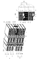
- the fuel cell stack FS shown in FIG. 1 includes a plurality of cell modules M in which a plurality of single cells C are stacked and integrated, and a seal plate P interposed between the cell modules M. Although two cell modules M and one seal plate P are shown in FIG. 1, in practice, more cell modules M and seal plates P are stacked.
- the fuel cell stack FS shown in the drawing is a collector plate at one end (right end in the drawing) of the laminated body including the cell module M and the seal plate P in the lamination direction.
- An end plate 56A is provided via a spacer, and an end plate 56B is provided at the other end similarly via a current collector plate or a spacer.
- the fastening plates 57A and 57B are provided on both sides (upper and lower surfaces in the drawing) on the long side of the unit cell C with respect to the stack, and on both sides on the short side , Reinforcing plates 58A, 58B are provided.
- the fuel cell stack FS has a case-integrated structure as shown in FIG. 1A, and the stack is restrained and pressurized in the stacking direction to set the predetermined unit cells C and seal plates P in a predetermined direction. Contact pressure is applied to maintain good gas sealability and conductivity.
- the unit cell C includes the membrane electrode assembly 1 having the frame 51 at its periphery, and a pair of separators 2A and 2B sandwiching the frame 51 and the membrane electrode assembly 1; A gas flow path of an anode and a cathode is formed between the electrode assembly 1 and the respective separators 2A and 2B.
- the membrane electrode assembly 1 is generally referred to as MEA (Membrane Electrode Assembly), and although detailed illustration is omitted, it is known that an electrolyte layer made of solid polymer is sandwiched between a cathode electrode layer and an anode electrode layer.
- MEA Membrane Electrode Assembly
- the frame 51 is integrated with the membrane electrode assembly 1 by resin molding (for example, injection molding).
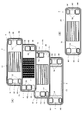
- the frame 51 has a rectangular shape with the membrane electrode assembly 1 at the center. Further, in the frame 51, three flow holes H1 to H3 and H4 to H6 for distributing the reaction gas are arranged on both sides of the short side.
- Each of the separators 2A and 3B is a rectangular metal plate member having substantially the same vertical and horizontal dimensions as the frame 5, and is made of, for example, stainless steel, and is formed into a suitable inverted shape by pressing.
- at least a central portion corresponding to the membrane electrode assembly 1 is formed to have an uneven cross-sectional shape.
- Both separators 2A and 2B have a cross-sectional uneven shape continuously in the direction of the long side, and make the membrane electrode assembly 1 contact the waveform convex portion, and between the membrane electrode assembly 1 by the waveform concave portion. Form gas flow paths for the anode and the cathode. Further, in each of the separators 2A and 2B, flow holes H1 to H6 equivalent to the flow holes H1 to H6 of the frame 51 are formed on both sides of the short side.
- the frame 51, the membrane electrode assembly 1 and the separators 2A and 2B are stacked to form a single cell C, and a predetermined number of the single cells C are stacked to form the previous cell module M.
- the through holes H1 to H6 of the frame 51 and the separators 2A and 2B are continuous with each other.
- a seal member described later is provided to form a flow path of the cooling liquid.
- the seal plate P is formed by molding a conductive single metal plate, and is formed in a rectangular shape having substantially the same vertical and horizontal dimensions as the unit cell C and adjacent to each other.
- a seal member described later is provided between the cell module M and the fuel cell M to form a flow path for the cooling liquid.
- flow holes H1 to H3 and H4 to H6 similar to the unit cell C are formed on both sides of the short side.
- the flow holes H1 to H6 communicate with each other, and as shown in FIG. 2B, manifolds M1 to M6 continuous in the stacking direction are formed.
- the manifolds M1 to M3 on the one end side which is the left side in the drawing are for cathode gas supply (M1), cooling fluid supply (M2), and anode gas discharge (M3) in this order from the top.
- manifolds M4 to M6 on the other end side on the right side in the figure are for anode gas supply (M4), cooling fluid discharge (M5), and cathode gas supply (from the top) M6).
- the anode gas is a hydrogen-containing gas.
- the cathode gas is an oxygen-containing gas, for example air.
- the cooling fluid is, for example, water.
- Seal members S1 and S2 are provided between the frame of the membrane electrode assembly 1 and the edges of the separators 2 and around the flow holes H1 to H6.
- an adhesive that exhibits sealing performance after the members are joined can be used for the sealing members S1 and S2.
- the seal members S2 around the flow holes H1 to H6 are not disposed at the corresponding locations as shown in FIG.
- the seal plate P includes seal members S3 and S4 that seal between the edge and the flow holes H1 to H6 and the adjacent cell module M. As described above, the seal plate P forms a flow path for the cooling fluid with the cell module M, and therefore, as shown in FIG. 3, around the flow holes H2 (H5) for the cooling fluid.
- the seal member (S4) is not disposed, or the seal member (S4) having an opening in part is disposed.
- the fuel cell stack FS formed by stacking the unit cells C and the seal plate P particularly, at least a part of the inner peripheral surface of the manifolds M3 and M6 for discharging the reaction gas is continuous in the stacking direction of the unit cells C. It is formed in a flat shape. More specifically, the fuel cell stack FS includes the inner peripheral surfaces of the manifolds M3 and M6 by the end surfaces of the lamination members which are the frame 51, the separators 2A and 2B and the seal plate P (inner peripheral surfaces of the flow holes H3 and H6). Are formed in a planar shape continuous in the stacking direction of the unit cells C. That is, the end faces of the laminated members (51, 2A, 2B, P) are continuous in the same plane on at least a part of the inner peripheral surfaces of the manifolds M3, M6.
- the fuel cell stack FS in this embodiment is installed in a posture in which the long side of the unit cell C is horizontal.
- the portion formed in a planar shape on the inner peripheral surface of the manifolds M3 and M6 is at least a lower portion in the direction of gravity.
- the flat portion may include other portions in addition to the lower portion, and may further include supply manifolds M1 and M4 in addition to the discharge manifolds M3 and M6. It may be formed on the inner circumferential surface of
- FIG. 4 is a perspective sectional view based on line XX in FIG. 3, and shows a portion of a manifold M3 for discharging anode gas.
- the flow direction of the gas in the manifold M3 is a downward direction indicated by an arrow, but as described above, when the posture of the combustion cell stack FS is that shown in FIG.
- the distribution direction is horizontal.
- the frame 51 of each single cell C, the separators 2A and 2B, and the seal plate P are flat on the inner peripheral portion of each flow hole H3. It has formation surface F1, F2, F3, F4. Then, at least a part of the inner peripheral surface of the manifold M3 is formed in a planar shape continuous in the stacking direction of the unit cells C by making the respective flat formation surfaces F1 to F4 mutually continuous in the same plane. .
- the frame 51 integrally has a rib 21 projecting on the surface of the cathode side (the lower side in FIG. 4) on the inner peripheral portion of the flow hole H3 and includes the rib 21.
- the inner peripheral surface of the flow through hole H3 is a flat surface F1.
- the seal member S1 around the flow holes H1 to H6 in the unit cell C is provided between the front end surface of the rib 21 and the cathode side separator 2B.
- the above-described open part for circulating the cathode gas can be provided by removing a part of the rib 21.
- the inner peripheral surfaces of the flow through holes H3 are flat formation surfaces F2 and F3.
- the seal plate P includes the seal member S4 that seals the periphery of the manifold M3 with the cell module M, as described above.
- the seal plate P is provided with an extension portion E having an end surface extending to the side of the manifold M3 and having the same plane as the inner peripheral surface of the manifold M3 in the seal member S4. That is, the seal plate P is the flat forming surface F4 in which the end face of the extension part E is continuous on the same plane as the inner peripheral surface of the manifold M3, and the extension part E to the lower side in the gravity direction as shown in FIG. Is provided.
- At least a portion of the inner peripheral surface of the manifold M3 includes the end surface (flat surface F4) of the extension E of the seal member S4 and is continuous in the stacking direction of the single cells C. It is formed flat.
- FIG. 4 exemplifies the manifold M3 for discharging the anode gas, it is of course possible to adopt the same configuration as the manifolds M1, M4 and M6 for other reaction gases.
- the fuel cell stack FS having the above-described configuration generates an electrochemical reaction by supplying an anode gas and a cathode gas to the anode electrode layer and the cathode electrode layer of the membrane electrode assembly 1 in each unit cell C. At this time, water is generated along with the power generation. The generated water is discharged mainly through the manifolds M3 and M6 for discharging the reaction gas.
- the seal member S4 of the seal plate P is provided with the extension portion E having the end face (F4) which is flush with the inner peripheral surfaces of the manifolds M3 and M6.
- the unevenness of the inner peripheral surfaces of the manifolds M3 and M6 in the portion where the seal plate P is interposed is eliminated.
- the fuel cell stack FS does not require a special member that covers the entire inner peripheral surface of the manifolds M3 and M6, and the manifold does not decrease the flowability of reaction gas or increase the manufacturing cost. You can discharge the generated water well through the
- the extension E of the seal member S4 is provided at least on the lower side in the gravity direction on the inner peripheral surface of the manifolds M3 and M6, the generated water is discharged more smoothly and rapidly can do.
- the frame 51 of each unit cell C and the separators 2A and 2B have flat formation surfaces F1 to F3 in the inner peripheral portion of the respective through holes H3. At least a portion of the inner peripheral surface of M6 is formed in a planar shape including the end surface (flat surface F4) of the extension E of the seal member S4 and continuous in the stacking direction of the single cells C.
- the fuel cell stack FS can discharge generated water more smoothly, and the end face (F1 to F4) of the laminated member which is the frame 51, the separators 2A and 2B and the seal plate P on the inner peripheral surface of the manifold M3. Even if the water is exposed, the drainage property is good, so that corrosion of the member due to generated water can be prevented.
- FIG. 5 is a view for explaining a second embodiment of the fuel cell according to the present invention, and is a perspective sectional view and an enlarged sectional view based on line XX in FIG. 3 as in FIG. That is, FIG. 5 shows a portion of the manifold M3 for discharging anode gas.
- the same components as those of the first embodiment are denoted by the same reference numerals, and the detailed description thereof is omitted.
- the frame 51 of each single cell C protrudes to the surface of at least one side of the frame 51 on the inner peripheral portion (edge) of each flow hole H3 to separate the separators 2A and 2B.
- the rib 21 covers the inner peripheral surface of the through hole H3 and the flat forming surface F1 including the side surface of the rib 21.
- the frame 51 of the illustrated example integrally has a rib 21 projecting to the surface on the cathode side (lower side in FIG. 5).
- the seal plate P has ribs 22 and 22 protruding at both ends in the stacking direction at the tip of the extension E of the seal member S4 and pressed against the cell modules M and M.
- the side surfaces of the ribs 22 and 22 And a flat forming surface F4. Therefore, in the fuel cell stack FS of this embodiment, the inner peripheral surface of the manifold M3 is formed in a planar shape in which the inner peripheral surface of the manifold M3 is continuous in the stacking direction by the frame 51 and the flat forming surfaces F1 and F4 of the seal plate P.
- the fuel cell stack FS having the above configuration can satisfactorily discharge generated water through the manifold M3 without causing a decrease in the flowability of reaction gas and an increase in manufacturing cost. it can.
- the fuel cell stack FS when the cell modules M and M and the seal plate P are stacked, the ribs 22 and 22 of the extension E are compressed between the cell modules M and M. As a result, the fuel cell stack FS can ensure a good seal surface pressure between the cell modules M, M and the seal plate P, and can more reliably prevent the entry of generated water between the layers. .
- the fuel cell stack FS covers the inner peripheral surface of the flow through hole H3 of the metallic separators 2A and 2B with the ribs 21 provided on the resin frame 51, the ribs 22 and 22 of the extension portion E Together with the improvement of the sealability, a sufficient waterproof function for the separators 2A and 2B can be obtained.
- the configuration of the fuel cell stack according to the present invention is not limited to the above embodiments only, and the details of the configuration may be changed as appropriate without departing from the scope of the present invention. It is possible to combine appropriately.
Landscapes
- Life Sciences & Earth Sciences (AREA)
- Engineering & Computer Science (AREA)
- Manufacturing & Machinery (AREA)
- Sustainable Development (AREA)
- Sustainable Energy (AREA)
- Chemical & Material Sciences (AREA)
- Chemical Kinetics & Catalysis (AREA)
- Electrochemistry (AREA)
- General Chemical & Material Sciences (AREA)
- Fuel Cell (AREA)
Abstract
Priority Applications (7)
| Application Number | Priority Date | Filing Date | Title |
|---|---|---|---|
| CN201580079890.2A CN107534179B (zh) | 2015-05-13 | 2015-05-13 | 燃料电池堆 |
| PCT/JP2015/063754 WO2016181523A1 (fr) | 2015-05-13 | 2015-05-13 | Empilement de piles à combustible |
| CA2985594A CA2985594C (fr) | 2015-05-13 | 2015-05-13 | Empilement de piles a combustible |
| EP15891847.4A EP3297081B1 (fr) | 2015-05-13 | 2015-05-13 | Empilement de piles à combustible |
| JP2017517539A JP6395122B2 (ja) | 2015-05-13 | 2015-05-13 | 燃料電池スタック |
| KR1020177034660A KR101859894B1 (ko) | 2015-05-13 | 2015-05-13 | 연료 전지 스택 |
| US15/573,017 US10396369B2 (en) | 2015-05-13 | 2015-05-13 | Fuel cell stack |
Applications Claiming Priority (1)
| Application Number | Priority Date | Filing Date | Title |
|---|---|---|---|
| PCT/JP2015/063754 WO2016181523A1 (fr) | 2015-05-13 | 2015-05-13 | Empilement de piles à combustible |
Publications (1)
| Publication Number | Publication Date |
|---|---|
| WO2016181523A1 true WO2016181523A1 (fr) | 2016-11-17 |
Family
ID=57247978
Family Applications (1)
| Application Number | Title | Priority Date | Filing Date |
|---|---|---|---|
| PCT/JP2015/063754 Ceased WO2016181523A1 (fr) | 2015-05-13 | 2015-05-13 | Empilement de piles à combustible |
Country Status (7)
| Country | Link |
|---|---|
| US (1) | US10396369B2 (fr) |
| EP (1) | EP3297081B1 (fr) |
| JP (1) | JP6395122B2 (fr) |
| KR (1) | KR101859894B1 (fr) |
| CN (1) | CN107534179B (fr) |
| CA (1) | CA2985594C (fr) |
| WO (1) | WO2016181523A1 (fr) |
Cited By (1)
| Publication number | Priority date | Publication date | Assignee | Title |
|---|---|---|---|---|
| JP2019121562A (ja) * | 2018-01-10 | 2019-07-22 | 本田技研工業株式会社 | 燃料電池及び燃料電池スタック |
Families Citing this family (1)
| Publication number | Priority date | Publication date | Assignee | Title |
|---|---|---|---|---|
| NL2021245B1 (en) * | 2018-07-04 | 2020-01-15 | Redstack Bv | Stack assembly |
Citations (5)
| Publication number | Priority date | Publication date | Assignee | Title |
|---|---|---|---|---|
| JP2010055892A (ja) * | 2008-08-27 | 2010-03-11 | Toyota Motor Corp | 燃料電池 |
| JP2010055856A (ja) * | 2008-08-27 | 2010-03-11 | Honda Motor Co Ltd | 燃料電池 |
| WO2010119658A1 (fr) * | 2009-04-15 | 2010-10-21 | トヨタ自動車株式会社 | Système de pile à combustible |
| JP2011044351A (ja) * | 2009-08-21 | 2011-03-03 | Toyota Motor Corp | 燃料電池スタック |
| WO2012117676A1 (fr) * | 2011-03-02 | 2012-09-07 | パナソニック株式会社 | Pile à combustible à électrolyte polymère |
Family Cites Families (11)
| Publication number | Priority date | Publication date | Assignee | Title |
|---|---|---|---|---|
| JP4576646B2 (ja) * | 1999-09-30 | 2010-11-10 | アイシン精機株式会社 | 燃料電池 |
| JP2004213972A (ja) * | 2002-12-27 | 2004-07-29 | Hitachi Ltd | 積層形燃料電池 |
| JP4551746B2 (ja) | 2004-11-24 | 2010-09-29 | 本田技研工業株式会社 | 燃料電池スタック |
| EP1734604B1 (fr) * | 2004-12-28 | 2013-04-03 | Panasonic Corporation | Pile a combustible et empilement de piles a combustible |
| WO2011114702A1 (fr) * | 2010-03-17 | 2011-09-22 | パナソニック株式会社 | Pile à combustible à électrolyte en polymère et empilement de piles à combustible équipé de celle-ci |
| US8974980B2 (en) * | 2010-06-01 | 2015-03-10 | Nissan Motor Co., Ltd. | Fuel cell |
| DE102011079860A1 (de) * | 2011-07-26 | 2013-01-31 | Robert Bosch Gmbh | Bremssystem für ein Fahrzeug und Verfahren zum Betreiben eines Bremssystems eines Fahrzeugs |
| JP5259888B1 (ja) * | 2011-08-02 | 2013-08-07 | パナソニック株式会社 | 高分子電解質形燃料電池 |
| CA2866812C (fr) * | 2012-03-09 | 2017-03-14 | Nissan Motor Co., Ltd. | Empilement de piles a combustible et plaque d'etancheite utilisee pour celui-ci |
| EP2919308B1 (fr) * | 2012-11-06 | 2016-10-19 | Panasonic Intellectual Property Management Co., Ltd. | Pile à combustible du type à polyélectrolyte |
| CA2920772C (fr) * | 2013-08-08 | 2018-04-17 | Nissan Motor Co., Ltd. | Ensemble d'electrodes membranaire, unite de pile a combustible et empilement de pile a combustible |
-
2015
- 2015-05-13 KR KR1020177034660A patent/KR101859894B1/ko not_active Expired - Fee Related
- 2015-05-13 CA CA2985594A patent/CA2985594C/fr active Active
- 2015-05-13 EP EP15891847.4A patent/EP3297081B1/fr not_active Not-in-force
- 2015-05-13 CN CN201580079890.2A patent/CN107534179B/zh not_active Expired - Fee Related
- 2015-05-13 US US15/573,017 patent/US10396369B2/en not_active Expired - Fee Related
- 2015-05-13 JP JP2017517539A patent/JP6395122B2/ja not_active Expired - Fee Related
- 2015-05-13 WO PCT/JP2015/063754 patent/WO2016181523A1/fr not_active Ceased
Patent Citations (5)
| Publication number | Priority date | Publication date | Assignee | Title |
|---|---|---|---|---|
| JP2010055892A (ja) * | 2008-08-27 | 2010-03-11 | Toyota Motor Corp | 燃料電池 |
| JP2010055856A (ja) * | 2008-08-27 | 2010-03-11 | Honda Motor Co Ltd | 燃料電池 |
| WO2010119658A1 (fr) * | 2009-04-15 | 2010-10-21 | トヨタ自動車株式会社 | Système de pile à combustible |
| JP2011044351A (ja) * | 2009-08-21 | 2011-03-03 | Toyota Motor Corp | 燃料電池スタック |
| WO2012117676A1 (fr) * | 2011-03-02 | 2012-09-07 | パナソニック株式会社 | Pile à combustible à électrolyte polymère |
Cited By (2)
| Publication number | Priority date | Publication date | Assignee | Title |
|---|---|---|---|---|
| JP2019121562A (ja) * | 2018-01-10 | 2019-07-22 | 本田技研工業株式会社 | 燃料電池及び燃料電池スタック |
| US11101470B2 (en) | 2018-01-10 | 2021-08-24 | Honda Motor Co., Ltd. | Fuel cell and fuel cell stack |
Also Published As
| Publication number | Publication date |
|---|---|
| KR20170139164A (ko) | 2017-12-18 |
| US20180166708A1 (en) | 2018-06-14 |
| JP6395122B2 (ja) | 2018-09-26 |
| EP3297081A4 (fr) | 2018-07-11 |
| CA2985594A1 (fr) | 2016-11-17 |
| JPWO2016181523A1 (ja) | 2018-03-29 |
| CN107534179B (zh) | 2021-07-30 |
| CA2985594C (fr) | 2019-07-30 |
| US10396369B2 (en) | 2019-08-27 |
| EP3297081B1 (fr) | 2020-06-10 |
| EP3297081A1 (fr) | 2018-03-21 |
| CN107534179A (zh) | 2018-01-02 |
| KR101859894B1 (ko) | 2018-05-18 |
Similar Documents
| Publication | Publication Date | Title |
|---|---|---|
| CN109616681B (zh) | 燃料电池用隔离部件和电芯 | |
| CA2801416C (fr) | Pile a combustible | |
| CN105144447B (zh) | 燃料电池堆的电池构造 | |
| JP5839307B2 (ja) | 燃料電池スタック | |
| CN102484264A (zh) | 燃料电池单元 | |
| EP3032626B1 (fr) | Ensemble d'électrodes membranaire, cellule individuelle de pile à combustible et empilement de pile à combustible | |
| JP5234446B2 (ja) | 燃料電池スタック用金属セパレータの積層性向上構造 | |
| JP5773232B2 (ja) | 燃料電池 | |
| US20060024560A1 (en) | Separator and cell using the same for use in solid polymer electrolyte fuel cell | |
| US20080166608A1 (en) | Fuel Cell and Fuel Cell Separator | |
| JP2015035311A (ja) | フレーム付き膜電極接合体、燃料電池単セル及び燃料電池スタック | |
| US7534518B2 (en) | Cell for solid polymer electrolyte fuel cell with improved gas flow sealing | |
| KR101859894B1 (ko) | 연료 전지 스택 | |
| JP6241594B2 (ja) | フレーム付き膜電極接合体、燃料電池単セル及び燃料電池スタック | |
| KR101963998B1 (ko) | 연료 전지 스택 | |
| JP6656596B2 (ja) | 燃料電池の単セル構造 | |
| JP2007250206A (ja) | 燃料電池 |
Legal Events
| Date | Code | Title | Description |
|---|---|---|---|
| 121 | Ep: the epo has been informed by wipo that ep was designated in this application |
Ref document number: 15891847 Country of ref document: EP Kind code of ref document: A1 |
|
| ENP | Entry into the national phase |
Ref document number: 2017517539 Country of ref document: JP Kind code of ref document: A |
|
| ENP | Entry into the national phase |
Ref document number: 2985594 Country of ref document: CA |
|
| WWE | Wipo information: entry into national phase |
Ref document number: 15573017 Country of ref document: US |
|
| NENP | Non-entry into the national phase |
Ref country code: DE |
|
| ENP | Entry into the national phase |
Ref document number: 20177034660 Country of ref document: KR Kind code of ref document: A |
|
| WWE | Wipo information: entry into national phase |
Ref document number: 2015891847 Country of ref document: EP |