WO2016181596A1 - Système de pile à combustible - Google Patents
Système de pile à combustible Download PDFInfo
- Publication number
- WO2016181596A1 WO2016181596A1 PCT/JP2016/001519 JP2016001519W WO2016181596A1 WO 2016181596 A1 WO2016181596 A1 WO 2016181596A1 JP 2016001519 W JP2016001519 W JP 2016001519W WO 2016181596 A1 WO2016181596 A1 WO 2016181596A1
- Authority
- WO
- WIPO (PCT)
- Prior art keywords
- fuel
- fuel cell
- combustion
- air
- cover
- Prior art date
- Legal status (The legal status is an assumption and is not a legal conclusion. Google has not performed a legal analysis and makes no representation as to the accuracy of the status listed.)
- Ceased
Links
Images


Classifications
-
- H—ELECTRICITY
- H01—ELECTRIC ELEMENTS
- H01M—PROCESSES OR MEANS, e.g. BATTERIES, FOR THE DIRECT CONVERSION OF CHEMICAL ENERGY INTO ELECTRICAL ENERGY
- H01M8/00—Fuel cells; Manufacture thereof
- H01M8/04—Auxiliary arrangements, e.g. for control of pressure or for circulation of fluids
- H01M8/04007—Auxiliary arrangements, e.g. for control of pressure or for circulation of fluids related to heat exchange
- H01M8/04014—Heat exchange using gaseous fluids; Heat exchange by combustion of reactants
- H01M8/04022—Heating by combustion
-
- H—ELECTRICITY
- H01—ELECTRIC ELEMENTS
- H01M—PROCESSES OR MEANS, e.g. BATTERIES, FOR THE DIRECT CONVERSION OF CHEMICAL ENERGY INTO ELECTRICAL ENERGY
- H01M8/00—Fuel cells; Manufacture thereof
- H01M8/04—Auxiliary arrangements, e.g. for control of pressure or for circulation of fluids
-
- H—ELECTRICITY
- H01—ELECTRIC ELEMENTS
- H01M—PROCESSES OR MEANS, e.g. BATTERIES, FOR THE DIRECT CONVERSION OF CHEMICAL ENERGY INTO ELECTRICAL ENERGY
- H01M8/00—Fuel cells; Manufacture thereof
- H01M8/04—Auxiliary arrangements, e.g. for control of pressure or for circulation of fluids
- H01M8/04007—Auxiliary arrangements, e.g. for control of pressure or for circulation of fluids related to heat exchange
- H01M8/04067—Heat exchange or temperature measuring elements, thermal insulation, e.g. heat pipes, heat pumps, fins
- H01M8/04074—Heat exchange unit structures specially adapted for fuel cell
-
- H—ELECTRICITY
- H01—ELECTRIC ELEMENTS
- H01M—PROCESSES OR MEANS, e.g. BATTERIES, FOR THE DIRECT CONVERSION OF CHEMICAL ENERGY INTO ELECTRICAL ENERGY
- H01M8/00—Fuel cells; Manufacture thereof
- H01M8/06—Combination of fuel cells with means for production of reactants or for treatment of residues
- H01M8/0606—Combination of fuel cells with means for production of reactants or for treatment of residues with means for production of gaseous reactants
- H01M8/0612—Combination of fuel cells with means for production of reactants or for treatment of residues with means for production of gaseous reactants from carbon-containing material
- H01M8/0618—Reforming processes, e.g. autothermal, partial oxidation or steam reforming
-
- H—ELECTRICITY
- H01—ELECTRIC ELEMENTS
- H01M—PROCESSES OR MEANS, e.g. BATTERIES, FOR THE DIRECT CONVERSION OF CHEMICAL ENERGY INTO ELECTRICAL ENERGY
- H01M8/00—Fuel cells; Manufacture thereof
- H01M8/10—Fuel cells with solid electrolytes
- H01M8/12—Fuel cells with solid electrolytes operating at high temperature, e.g. with stabilised ZrO2 electrolyte
- H01M2008/1293—Fuel cells with solid oxide electrolytes
-
- H—ELECTRICITY
- H01—ELECTRIC ELEMENTS
- H01M—PROCESSES OR MEANS, e.g. BATTERIES, FOR THE DIRECT CONVERSION OF CHEMICAL ENERGY INTO ELECTRICAL ENERGY
- H01M8/00—Fuel cells; Manufacture thereof
- H01M8/24—Grouping of fuel cells, e.g. stacking of fuel cells
- H01M8/241—Grouping of fuel cells, e.g. stacking of fuel cells with solid or matrix-supported electrolytes
- H01M8/2425—High-temperature cells with solid electrolytes
-
- H—ELECTRICITY
- H01—ELECTRIC ELEMENTS
- H01M—PROCESSES OR MEANS, e.g. BATTERIES, FOR THE DIRECT CONVERSION OF CHEMICAL ENERGY INTO ELECTRICAL ENERGY
- H01M8/00—Fuel cells; Manufacture thereof
- H01M8/24—Grouping of fuel cells, e.g. stacking of fuel cells
- H01M8/2465—Details of groupings of fuel cells
- H01M8/2484—Details of groupings of fuel cells characterised by external manifolds
-
- Y—GENERAL TAGGING OF NEW TECHNOLOGICAL DEVELOPMENTS; GENERAL TAGGING OF CROSS-SECTIONAL TECHNOLOGIES SPANNING OVER SEVERAL SECTIONS OF THE IPC; TECHNICAL SUBJECTS COVERED BY FORMER USPC CROSS-REFERENCE ART COLLECTIONS [XRACs] AND DIGESTS
- Y02—TECHNOLOGIES OR APPLICATIONS FOR MITIGATION OR ADAPTATION AGAINST CLIMATE CHANGE
- Y02E—REDUCTION OF GREENHOUSE GAS [GHG] EMISSIONS, RELATED TO ENERGY GENERATION, TRANSMISSION OR DISTRIBUTION
- Y02E60/00—Enabling technologies; Technologies with a potential or indirect contribution to GHG emissions mitigation
- Y02E60/30—Hydrogen technology
- Y02E60/50—Fuel cells
Definitions
- This disclosure relates to a fuel cell system.
- the ratio of the fuel used for power generation in the fuel cell with respect to the total amount of fuel is set to 70 to 80% (hereinafter, this ratio is referred to as the fuel utilization rate), and the remaining 20 to 30% of fuel is used in the combustion section. Often used for combustion fuel.
- the calorific value of the combustion section decreases due to a decrease in the amount of combustible gas, a sufficient amount of heat for maintaining the temperature suitable for the reforming reaction of the reformer and the temperature of the fuel cell that affects the power generation voltage can be obtained. It becomes difficult. Therefore, for example, it is necessary to improve the heat insulation performance of the housing portion that houses the fuel cell stack and the heat recovery performance of a heat exchanger that collects the combustion heat of the combustion portion. As a result, the manufacturing cost of the fuel cell system may be increased, the system configuration may be complicated, and the system may be increased in size.
- the fuel utilization rate of the fuel cell is an important parameter for determining the power generation efficiency, and is thus determined by the power generation state.
- the air utilization factor of the fuel cell can vary depending on the operating state, the environmental temperature, and the like in order to optimally control the temperature and temperature unevenness of the fuel cell that affect the generated voltage. For example, when the fuel cell is operated at 70% fuel utilization and the fuel cell air utilization is 35%, lean combustion occurs in the combustion section. Therefore, in this case, there is a high possibility that the combustibility of the combustion section is deteriorated (for example, misfire).
- Patent Document 1 proposes a method for suppressing deterioration in combustibility of the combustion section by setting fresh air different from the cathode offgas from the fuel cell to an optimal air ratio and sending it to the combustion section. Yes.
- Patent Document 2 As shown in FIG. 5, a porous body 21 having air permeability and electrical insulation is provided in the combustion section of the fuel cell system in a state extending between the fuel ejection section 18 and the air ejection section 19, thereby A method for suppressing deterioration in combustibility of the combustion section 34 has been proposed.
- Patent Document 3 as shown in FIG. 6, a method is proposed in which a cover 17 closes the lateral side of the air flow portion 8 of the cell 9 to suppress deterioration in combustibility of the combustion portion.
- Patent Document 4 in order to promote mixing of unused reformed gas and air from a fuel cell, a long member (vortex generator) is provided so as to straddle a plurality of fuel cells. A method for suppressing the deterioration of flammability is proposed.
- Japanese Patent Publication No. 2013-157274 Japanese Patent Publication No. 2013-206603 Japanese Patent Publication No. 2013-222592 Japanese Patent Publication No. 2011-150842
- the solid oxide fuel Provided is a fuel cell system in which reformed gas discharged from a battery and air can be mixed in a combustion part more appropriately than in the past. Moreover, the fuel cell system which can perform the heating of the reformer by the heat of such a combustion part more appropriately than before is provided.
- a fuel cell system includes a reformer that generates reformed gas by reforming raw fuel, and solid oxide that generates power by reaction of the reformed gas and air.
- the raw fuel is reformed by the cover It is configured to send fuel balloon the air to the mouth end of the fuel assembly unit.
- the solid oxide fuel is configured as described above and increases the fuel utilization rate in order to improve the power generation efficiency of the solid oxide fuel cell.
- Mixing in the combustion part of the reformed gas and air discharged from the battery can be performed more appropriately than in the past.
- the reformer can be heated more appropriately by the heat of the combustion section than in the past.
- FIG. 1 is a schematic diagram illustrating an example of a configuration of a fuel cell system according to an embodiment.
- FIG. 2 is a perspective view illustrating an example of a peripheral portion of the fuel assembly portion of the fuel cell system according to the embodiment.
- FIG. 3 is a diagram illustrating an example of a fluid simulation result in the peripheral portion of the fuel assembly portion of the fuel cell system according to the embodiment.
- FIG. 4 is a diagram illustrating an example of a peripheral portion of a fuel assembly portion of a fuel cell system according to a modification of the embodiment.
- FIG. 5 is a schematic diagram showing an example of the configuration of a conventional fuel cell system.
- FIG. 6 is a schematic diagram showing an example of the configuration of a conventional fuel cell system.
- the inventors diligently studied the problems of the conventional example regarding appropriate mixing in the combustion part of the reformed gas and air discharged from the solid oxide fuel cell, and obtained the following knowledge.
- Patent Document 3 has a problem that it is difficult to apply in a configuration in which the cover body 17 cannot be disposed on the side of the air flow portion 8.
- a fuel cell system includes a reformer that generates reformed gas by reforming raw fuel, a solid oxide fuel cell that generates power by reaction of the reformed gas and air, A fuel assembly portion adjacent to the solid oxide fuel cell, where the reformed gas remaining after the reaction of the solid oxide fuel cell collects, and an air passage formed along the outer periphery of the fuel assembly portion A combustion section that burns the reformed gas by mixing the air flowing through the air passage section with the reformed gas that has exited from the fuel outlet of the fuel assembly section, and a reformer from the air passage section to the combustion section And a cover provided so as to prevent the flow of air in the direction along, and reforming of the raw fuel by the reformer is performed using the combustion heat of the combustion section, and the cover is a fuel assembly section The air is sent to the fuel outlet side.
- the air from the solid oxide fuel cell passes through the air passage part, the air is guided to the fuel outlet of the fuel assembly part by the cover.
- the reformed gas and air from the fuel outlet are mixed and burned in the combustion section.
- the combustion heat of the combustion part can be appropriately transferred to the reformer.
- fuel combustion in the combustion section can be stably performed without causing misfire or the like in the combustion section. . That is, it is possible to suppress a decrease in the amount of heat generated in the combustion section and a deterioration in combustibility. For this reason, unburned gas components (CO etc.) in combustion exhaust gas can be reduced. Further, by effectively utilizing the combustion heat of the combustion section, it is possible to appropriately heat the reformer adjacent to the fuel assembly section. In addition, an increase in the manufacturing cost of the fuel cell system can be suppressed, and a compact configuration of the combustion unit can be maintained.
- the fuel cell system according to the second aspect of the present disclosure is the fuel cell system according to the first aspect.
- the air used for combustion in the combustion section is cathode offgas discharged from the solid oxide fuel cell. Good.
- the fuel cell system can be configured simply.
- the manufacturing cost of the fuel cell system can be reduced.
- the fuel cell system according to a third aspect of the present disclosure is the fuel cell system according to the first aspect or the second aspect, wherein the cover is inclined downward in the vertical direction in the direction from the reformer to the fuel assembly. May be.
- a space between the cover and the upper wall portion of the fuel assembly portion can be appropriately secured, so that air can be easily delivered to the fuel outlet side of the fuel assembly portion.
- positioning which a cover body wraps the flame of a combustion part can be reduced.
- a fuel cell system according to a fourth aspect of the present disclosure is the fuel cell system according to any one of the first aspect, the second aspect, and the third aspect, wherein the first flame holding cover covers the combustion portion from above the cover. May be provided.
- the fuel cell system according to the fifth aspect of the present disclosure is the fuel cell system according to the fourth aspect, in which the first flame holding cover is inclined upward in the vertical direction in the direction from the reformer to the fuel assembly. May be.
- the first flame holding cover is arranged to wrap the flame of the combustion part. Therefore, since the flame holding effect of the combustion part by a 1st flame holding cover is acquired, possibility that a combustion part will misfire can be reduced.
- a fuel cell system according to a sixth aspect of the present disclosure is the fuel cell system according to any one of the first aspect, the second aspect, the third aspect, the fourth aspect, and the fifth aspect.
- a second flame holding cover that covers the combustion part from above and protrudes from the fuel assembly part may be provided.
- the second flame holding cover is arranged to wrap the flame of the combustion part. Therefore, since the flame holding effect of the combustion part by a 2nd flame holding cover is acquired, possibility that a combustion part will misfire can be reduced.
- a fuel cell system is the fuel cell according to any one of the first aspect, the second aspect, the third aspect, the fourth aspect, the fifth aspect, and the sixth aspect.
- the cover may include an opening for blowing out air from the air passage portion to the combustion portion, and the opening may be provided directly below the fuel outlet.
- FIG. 1 is a schematic diagram illustrating an example of a configuration of a fuel cell system according to an embodiment.
- FIG. 1 shows a side view of the fuel cell system 100.
- gravity acts from “upper” to “lower”, and in the following description, the vertical direction may be referred to as the vertical direction.
- the flow of raw fuel and reformed gas is indicated by a solid line
- the flow of air is indicated by a dotted line
- the flow of combustion exhaust gas is indicated by a one-dot chain line.
- the fuel cell system 100 includes a reformer 4, a solid oxide fuel cell 2, a fuel assembly 9, a raw fuel path 1, a reformed gas path 16, and an air path 12. And an exhaust gas path 19.
- the reformer 4 generates reformed gas by reforming the raw fuel. Specifically, in the reformer 4, the raw fuel from the raw fuel path 1 undergoes a reforming reaction, and a hydrogen-containing reformed gas is generated.
- the reforming reaction may take any form, and examples thereof include a steam reforming reaction, an autothermal reaction, and a partial oxidation reaction.
- the reforming reaction is a steam reforming reaction
- an evaporator that generates steam and a water supplier that supplies water to the evaporator are provided.
- the fuel cell system 100 is further provided with an air supply device for supplying air to the reformer 4.
- an evaporation unit (not shown) is provided on the upstream side of the raw fuel path 1. Thereby, the water for reforming reaction is evaporated using the residual heat of the combustion exhaust gas flowing through the exhaust gas path 19, and the raw fuel and the steam are mixed through the raw fuel path 1 and sent to the reformer 4.
- the raw fuel is a fuel containing an organic compound composed of at least carbon and hydrogen such as city gas, natural gas, and LPG mainly composed of methane.
- the reformer 4 is formed in an annular shape (for example, an annular shape) surrounding the periphery of the fuel assembly portion 9 in a plan view in the vertical direction.
- the air passage part 3 and the combustion part 34 are formed along the outer periphery of the fuel assembly part 9.
- an annular (for example, annular) air passage portion 3 and a combustion portion 34 are formed between the reformer 4 and the fuel assembly portion 9. Details of the periphery of the fuel assembly 9 will be described later.
- the reformer 4 is heated to a temperature suitable for the reforming reaction (for example, about 600 to 700 ° C.) by the heat of the combustion section 34 and the heat of the combustion exhaust gas.
- the solid oxide fuel cell 2 generates electric power by the reaction between the reformed gas and air.
- the fuel cell stack may be, for example, a flat plate stack in which members such as a plurality of flat fuel cells and interconnectors are stacked, or a plurality of cylindrical fuel cells (cell tubes) and members such as interconnectors. It may be a cylindrical stack of bundles (fixed in a bundle).
- the reformed gas exiting from the reformer 4 is sufficiently mixed in the hollow plate-shaped reformed gas passage 16 and then uniformly distributed into the hollow regions inside the solid oxide fuel cells 2. Distributed and supplied. As a result, the reformed gas that has exited from the reformed gas path 16 rises in the respective hollow regions of the solid oxide fuel cell 2 to generate hydrogen (reformation) required for the power generation reaction of the solid oxide fuel cell 2. Gas) is supplied to the solid oxide fuel cell 2.
- oxygen (air) required for the power generation reaction of the solid oxide fuel cell 2 is supplied to the fuel cell stack through a route different from these.
- an air supply device (not shown) is provided on the upstream side of the air path 12.
- the air supply device include a blower.
- the air pressure-fed in the air path 12 by the air supply device passes through an appropriate filter (not shown) and then is sent to the downstream portion of the air path 12.
- the air flowing through the air path 12 is heated by heat exchange with the combustion exhaust gas flowing through the exhaust gas path 19.
- the flow path member constituting the exhaust gas path 19 and the flow path member constituting the air path 12 pass through the heat exchanger 5. Thereby, normal temperature air is heated to about 600 degreeC.
- the hot combustion exhaust gas is cooled to about 300 ° C.
- the combustion exhaust gas is then sent to a heat exchanger (not shown) for generating hot water for hot water supply.
- the downstream portion of the air path 12 is located near the lower end of the center of the fuel cell stack, and a plurality of air outlets 23 form the air path 12 in the downstream portion. It is formed substantially evenly in the circumferential direction of the flow path member.
- high-temperature air for example, about 600 to 700 ° C.
- exiting from the air outlet 23 rises through the gaps between adjacent solid oxide fuel cells 2, and generates a power generation reaction of the solid oxide fuel cells 2.
- Necessary oxygen (air) is supplied to the solid oxide fuel cell 2.
- a power generation reaction occurs between hydrogen and carbon monoxide in the reformed gas and oxygen in the air, and water vapor and carbon dioxide. Gas is generated and at the same time an electromotive force is generated.
- the power generation components hydrogen and carbon monoxide
- the power generation reaction about 60% to 80% are used for the power generation reaction, and about 20% to 40% of unused power generation components are located above the fuel cell stack. Burned. Then, the combustion heat of the unused reformed gas is used for the reforming reaction of the reformer 4.
- about 30% of oxygen in the air is used for the power generation reaction, and air containing unused oxygen is also combusted above the fuel cell stack.
- unused reformed gas is blown out from the fuel blowing portion at the upper end of each of several tens to several hundreds of solid oxide fuel cells, and the reformed gas is burned. For this reason, incomplete combustion may occur due to partial misfire or the like in the combustion portion in the fuel blowing portions of several solid oxide fuel cells.
- a configuration is used in which the unused reformed gases of the solid oxide fuel cell 2 are collected in the fuel collecting section 9. That is, the fuel assembly 9 is provided adjacent to the solid oxide fuel cell 2, and the reformed gas remaining after the reaction of the solid oxide fuel cell 2 collects.
- the combustion unit 34 burns the reformed gas by mixing the air flowing through the air passage unit 3 with the reformed gas exiting from the fuel outlet 13 of the fuel collecting unit 9.
- the air used for the combustion of the combustion unit 34 may be air supplied by an air supply device (not shown), or may be cathode off gas discharged from the solid oxide fuel cell 2.
- the air used for the combustion of the combustion unit 34 is the cathode offgas discharged from the solid oxide fuel cell 2.
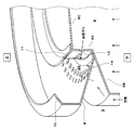
- FIG. 2 is a perspective view illustrating an example of a peripheral portion of the fuel assembly portion of the fuel cell system according to the embodiment.
- gravity acts from “upper” to “lower”.
- the reformed gas flow is indicated by a solid line, and the air flow is indicated by a dotted line.
- a hollow plate-like (here, disc-like) fuel assembly portion 9 is provided above a fuel cell stack including the solid oxide fuel cell 2. As described above, the interior of each solid oxide fuel cell 2 and the interior of the fuel assembly 9 communicate with each other so that unused reformed gas collects in the fuel assembly 9.
- the fuel assembly portion 9 includes a cylindrical side wall portion 9A standing upright in the vertical direction, and a disc-shaped lid portion extending horizontally from the upper end portion of the side wall portion 9A toward the center portion. 9C and an annular upper wall 9B extending outward from the lower end of the side wall 9A.
- Dozens of fuel outlets 13 are substantially even in the circumferential direction at appropriate positions in the vertical direction of the side wall 9A of the fuel assembly 9. Is formed. As a result, the reformed gas in the fuel assembly 9 is redistributed at the fuel outlet 13 and blown out horizontally to the combustion section 34. Therefore, the partial misfire which generate
- the cover body 8 is provided so as to prevent the flow of air in the direction along the reformer 4 from the air passage portion 3 to the combustion portion 34 (that is, the vertical direction), and toward the fuel outlet 13 side of the fuel assembly portion 9. It is configured to send air.
- the cover body 8 is made of, for example, an annular stainless steel metal plate, and the inner end portion of the metal plate is fixed to the end portion of the upper wall portion 9B by appropriate fixing means such as welding. ing. Then, several tens of air outlets 14 (for example, round holes which are openings for blowing out air) are provided at appropriate positions on the cover 8 in the vicinity of the upper wall portion 9B. ) Over the circumferential direction. Thereby, it is possible to prevent air from passing between the reformer 4 and the fuel collecting portion 9 without being involved in the fuel combustion of the combustion portion 34.
- the cover 8 has a configuration in which air is blown out from the air blowing port 14 to the fuel blowing port 13 side at a desired flow rate, and passage of air passing through the air passage 3 can be prohibited. Accordingly, almost the entire amount of air can be used for fuel combustion in the combustion section 34.
- air can be appropriately involved in the fuel combustion of the combustion section 34 by shortening the distance between the fuel collecting section 9 and the reformer 4 without using the cover 8 described above.
- the distance between the flame of the combustion section 34 and the reformer 4 that is, the reforming catalyst
- the reforming catalyst may be deteriorated due to the influence of the flame of the combustion section 34.
- the distance between the fuel assembly portion 9 and the reformer 4 is shortened, the flow velocity of the air passing through the air passage portion 3 is increased, and there is a possibility that the flame of the combustion portion 34 is blown away.
- such a possibility can be reduced by using the cover 8 described above.
- the distance L (see FIG. 1) between the reformer 4 and the fuel outlet 13 of the fuel assembly 9 is about 30 mm or more.
- the cover 8 is inclined downward in the vertical direction in the direction from the reformer 4 to the fuel assembly 9.
- the cover 8 is inclined by about 30 ° with respect to the horizontal direction.
- the cover body 8 since the flame of the combustion section 34 is formed obliquely upward outward from the fuel outlet 13, when the cover body 8 is inclined by about 30 ° with respect to the horizontal direction, the cover body 8 is moved to the combustion section 34. It will be arranged to wrap the flame. Therefore, since the flame holding effect of the combustion part 34 by the cover 8 is acquired, possibility that the combustion part 34 will misfire can be reduced.
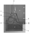
- FIG. 3 is a diagram showing an example of a fluid simulation result in the peripheral part of the fuel assembly part of the fuel cell system according to the embodiment.
- the gas flow velocity distribution in the vicinity of the fuel outlet 13 and the air outlet 14 is depicted in a contour diagram. According to the result of this fluid simulation, it can be visualized that air can be easily delivered to the combustion section 34 by inclining the cover 8 by about 30 ° with respect to the horizontal direction.
- the upper wall portion 9B of the fuel assembly portion 9 is also inclined downward in the vertical direction in the direction from the fuel assembly portion 9 to the reformer 4. Thereby, even when a cover body is formed horizontally, air can be easily delivered to the combustion unit 34. However, as in this example, it is advantageous to make both the cover 8 and the upper wall portion 9B inclined to facilitate air delivery to the combustion portion 34.
- the first flame holding cover 10 covers the combustion part 34 from above the cover body 8. Further, the first flame holding cover 10 is inclined upward in the vertical direction in the direction from the reformer 4 to the fuel collecting portion 9.
- the first flame holding cover 10 is made of, for example, an annular stainless steel metal plate, and this metal plate is held by the cover 8 and inward from the reformer 4 so as to wrap the combustion part 34. Is extended (projected) by a predetermined width dimension obliquely above.
- the first flame holding cover 10 is arranged to wrap the flame of the combustion unit 34.
- the flame holding effect of the combustion part 34 by the 1st flame holding cover 10 is acquired, possibility that the combustion part 34 will misfire can be reduced. That is, even when the fuel utilization rate of the solid oxide fuel cell 2 is increased and the calorific value of the combustion unit 34 is reduced, the flame of the combustion unit 34 is held by the first flame holding cover 10 and the combustion unit 34 is maintained. The occurrence of misfire can be suppressed.
- the first flame holding cover 10 Even when the flame of the combustion unit 34 is extended due to some state change of the combustion unit 34 (for example, deterioration of air diffusion, extreme change of gas flow rate, etc.), the first flame holding cover 10 The reformer 4 can be protected from reaching flames up to four.
- the second flame holding cover 11 covers the combustion part 34 from above the cover 8 and protrudes from the fuel assembly part 9.
- the second flame holding cover 11 is made of, for example, an annular stainless steel metal plate, and the inner end portion of this metal plate is fixed to the outer end portion of the lid portion 9C by appropriate fixing means such as welding. Has been.
- the metal plate extends (projects) by a predetermined width dimension outwardly and obliquely upward from the upper end portion of the side wall portion 9A where the fuel outlet 13 is formed so as to wrap the combustion portion 34.
- the second flame holding cover 11 is disposed so as to wrap the flame of the combustion section 34. Therefore, since the flame holding effect of the combustion part 34 by the 2nd flame holding cover 11 is acquired, possibility that the combustion part 34 will misfire can be reduced. That is, even when the fuel utilization rate of the solid oxide fuel cell 2 is increased and the calorific value of the combustion part 34 is reduced, the flame of the combustion part 34 is held by the second flame holding cover 11, and the combustion part 34 The occurrence of misfire can be suppressed.
- FIG. 4 is a diagram illustrating an example of a peripheral portion of a fuel assembly portion of a fuel cell system according to a modification of the embodiment.
- FIG. 4A shows a plan view of the periphery of the fuel assembly 9 in the vertical direction.
- FIG. 4B shows an arrow view taken along the line BB in FIG. 4A.
- the air outlet 14 closest to the fuel assembly portion 9 among the plurality of stages of air outlets 14 formed in the cover 8 is provided directly below the fuel outlet 13.
- FIG. 4 for the purpose of facilitating understanding of the drawing, the state of the flame formed in the fuel outlet 13 when the combustion unit 34 ignites is shown in a dot pattern, and the air outlet 14 is a fuel assembly. Only the round hole closest to the part 9 is shown.
- the combustion unit 34 In the case of ignition of the combustion unit 34 at the start of the fuel cell system 100, or when the flame of the combustion unit 34 disappears due to some state change during the operation of the fuel cell system 100, the combustion unit 34 satisfies the combustion condition. Then, the combustion unit 34 is ignited by an igniter (not shown). Examples of the igniter include a heater and a spark plug.
- the air outlet 14 is provided between the adjacent fuel outlets 13, the air from the air outlet 14 blocks between the flames formed in the adjacent fuel outlets 13. Therefore, it is difficult to transfer the flame between the two, which may cause partial misfiring of the combustion part 34 or poor ignition.
- the air outlet 14 is provided directly below the fuel outlet 13, and thus such a possibility can be reduced. That is, since it becomes difficult for air to pass between the flames formed in the adjacent fuel outlets 13, the flames are easily transferred from the ignition point of the combustion unit 34 to the entire circumference.
- one embodiment of the present disclosure can be used in, for example, a fuel cell system.
Landscapes
- Engineering & Computer Science (AREA)
- Chemical & Material Sciences (AREA)
- Life Sciences & Earth Sciences (AREA)
- Manufacturing & Machinery (AREA)
- Sustainable Development (AREA)
- Sustainable Energy (AREA)
- Chemical Kinetics & Catalysis (AREA)
- Electrochemistry (AREA)
- General Chemical & Material Sciences (AREA)
- Combustion & Propulsion (AREA)
- Fuel Cell (AREA)
Abstract
La présente invention porte sur un système de pile à combustible qui est pourvu : d'un reformeur destiné à générer un gaz reformé par reformage de combustible brut ; d'une pile à combustible à oxyde solide destinée à générer de l'électricité par la réaction entre le gaz reformé et l'air ; d'un collecteur de combustible destiné à récupérer le gaz reformé restant après la réaction de la pile à combustible à oxyde solide, le collecteur de combustible étant disposé de manière adjacente à la pile à combustible à oxyde solide ; d'une unité de passage d'air formée le long de la périphérie extérieure du collecteur de combustible ; d'une unité de combustion destinée à brûler le gaz reformé par mélange de l'air s'écoulant à travers l'unité de passage d'air avec le gaz reformé sortant d'une buse de combustible du collecteur de combustible ; d'un couvercle disposé de manière à empêcher l'écoulement de l'air dans la direction le long du réformateur, à partir de l'unité de passage d'air dans l'unité de combustion, le combustible brut étant reformé par le reformeur par l'utilisation de la chaleur de combustion de l'unité de combustion, et le couvercle étant configuré de manière à envoyer l'air à la buse de combustible du collecteur de combustible.
Priority Applications (3)
| Application Number | Priority Date | Filing Date | Title |
|---|---|---|---|
| US15/572,113 US20180145347A1 (en) | 2015-05-11 | 2016-03-16 | Fuel cell system |
| JP2017517592A JP6262403B2 (ja) | 2015-05-11 | 2016-03-16 | 燃料電池システム |
| EP16792331.7A EP3297079B1 (fr) | 2015-05-11 | 2016-03-16 | Système de pile à combustible |
Applications Claiming Priority (2)
| Application Number | Priority Date | Filing Date | Title |
|---|---|---|---|
| JP2015-096796 | 2015-05-11 | ||
| JP2015096796 | 2015-05-11 |
Publications (1)
| Publication Number | Publication Date |
|---|---|
| WO2016181596A1 true WO2016181596A1 (fr) | 2016-11-17 |
Family
ID=57248864
Family Applications (1)
| Application Number | Title | Priority Date | Filing Date |
|---|---|---|---|
| PCT/JP2016/001519 Ceased WO2016181596A1 (fr) | 2015-05-11 | 2016-03-16 | Système de pile à combustible |
Country Status (4)
| Country | Link |
|---|---|
| US (1) | US20180145347A1 (fr) |
| EP (1) | EP3297079B1 (fr) |
| JP (1) | JP6262403B2 (fr) |
| WO (1) | WO2016181596A1 (fr) |
Cited By (1)
| Publication number | Priority date | Publication date | Assignee | Title |
|---|---|---|---|---|
| EP3392944A1 (fr) * | 2017-04-18 | 2018-10-24 | Panasonic Intellectual Property Management Co., Ltd. | Système de piles à combustible |
Citations (6)
| Publication number | Priority date | Publication date | Assignee | Title |
|---|---|---|---|---|
| JP2002053302A (ja) * | 2000-08-09 | 2002-02-19 | Sanyo Electric Co Ltd | 燃料改質器用バーナ |
| JP2004156895A (ja) * | 2002-10-16 | 2004-06-03 | Matsushita Electric Ind Co Ltd | バーナ、水素発生装置、及び、燃料電池発電システム |
| JP2010032184A (ja) * | 2008-07-31 | 2010-02-12 | Tokyo Gas Co Ltd | 燃料電池の改質器用バーナとそれを備えた改質器 |
| JP2015011810A (ja) * | 2013-06-27 | 2015-01-19 | Toto株式会社 | 固体酸化物型燃料電池装置の製造方法及び製造装置 |
| JP2015185493A (ja) * | 2014-03-26 | 2015-10-22 | Toto株式会社 | 固体酸化物形燃料電池装置 |
| JP2015187952A (ja) * | 2014-03-27 | 2015-10-29 | Toto株式会社 | 固体酸化物形燃料電池装置 |
Family Cites Families (6)
| Publication number | Priority date | Publication date | Assignee | Title |
|---|---|---|---|---|
| EP1411573A2 (fr) * | 2002-10-16 | 2004-04-21 | Matsushita Electric Industrial Co., Ltd. | Brûleur, générateur d'hydrogène et système de génération électrique à pile à combustible |
| US8920997B2 (en) * | 2007-07-26 | 2014-12-30 | Bloom Energy Corporation | Hybrid fuel heat exchanger—pre-reformer in SOFC systems |
| JP5317791B2 (ja) * | 2009-03-27 | 2013-10-16 | 株式会社日立製作所 | 燃料電池発電モジュール |
| CN104253278B (zh) * | 2013-06-27 | 2018-01-02 | Toto株式会社 | 固体氧化物型燃料电池装置及其制造方法、制造装置 |
| US9520601B2 (en) * | 2013-08-29 | 2016-12-13 | Delphi Technologies, Inc. | Heater and method of operating |
| JP6785441B2 (ja) * | 2016-02-16 | 2020-11-18 | パナソニックIpマネジメント株式会社 | 高温動作型燃料電池モジュール |
-
2016
- 2016-03-16 EP EP16792331.7A patent/EP3297079B1/fr active Active
- 2016-03-16 JP JP2017517592A patent/JP6262403B2/ja active Active
- 2016-03-16 WO PCT/JP2016/001519 patent/WO2016181596A1/fr not_active Ceased
- 2016-03-16 US US15/572,113 patent/US20180145347A1/en not_active Abandoned
Patent Citations (6)
| Publication number | Priority date | Publication date | Assignee | Title |
|---|---|---|---|---|
| JP2002053302A (ja) * | 2000-08-09 | 2002-02-19 | Sanyo Electric Co Ltd | 燃料改質器用バーナ |
| JP2004156895A (ja) * | 2002-10-16 | 2004-06-03 | Matsushita Electric Ind Co Ltd | バーナ、水素発生装置、及び、燃料電池発電システム |
| JP2010032184A (ja) * | 2008-07-31 | 2010-02-12 | Tokyo Gas Co Ltd | 燃料電池の改質器用バーナとそれを備えた改質器 |
| JP2015011810A (ja) * | 2013-06-27 | 2015-01-19 | Toto株式会社 | 固体酸化物型燃料電池装置の製造方法及び製造装置 |
| JP2015185493A (ja) * | 2014-03-26 | 2015-10-22 | Toto株式会社 | 固体酸化物形燃料電池装置 |
| JP2015187952A (ja) * | 2014-03-27 | 2015-10-29 | Toto株式会社 | 固体酸化物形燃料電池装置 |
Cited By (2)
| Publication number | Priority date | Publication date | Assignee | Title |
|---|---|---|---|---|
| EP3392944A1 (fr) * | 2017-04-18 | 2018-10-24 | Panasonic Intellectual Property Management Co., Ltd. | Système de piles à combustible |
| US11050067B2 (en) | 2017-04-18 | 2021-06-29 | Panasonic Intellectual Property Management Co., Ltd. | Fuel cell system |
Also Published As
| Publication number | Publication date |
|---|---|
| JP6262403B2 (ja) | 2018-01-17 |
| EP3297079B1 (fr) | 2020-01-15 |
| EP3297079A4 (fr) | 2018-04-11 |
| JPWO2016181596A1 (ja) | 2017-09-28 |
| US20180145347A1 (en) | 2018-05-24 |
| EP3297079A1 (fr) | 2018-03-21 |
Similar Documents
| Publication | Publication Date | Title |
|---|---|---|
| JP6846711B2 (ja) | 高温動作型燃料電池システム | |
| JP5851863B2 (ja) | 燃料電池モジュール | |
| JP6280470B2 (ja) | 燃料電池モジュール | |
| JP6280431B2 (ja) | 燃料電池モジュール | |
| JP2017105695A (ja) | 水素生成装置及び燃料電池システム | |
| US11050067B2 (en) | Fuel cell system | |
| KR20130132457A (ko) | 고체 산화물 연료 전지 시스템과 고체 산화물 연료 전지 시스템을 작동하는 방법 | |
| CA2967940C (fr) | Configuration de bruleur catalytique | |
| JP2019102437A (ja) | 固体酸化物形燃料電池システム | |
| JP7178639B2 (ja) | 燃料電池システム | |
| JP7182263B2 (ja) | 固体酸化物形燃料電池システム | |
| JP6374273B2 (ja) | 燃料電池モジュール | |
| JP6262403B2 (ja) | 燃料電池システム | |
| JP2014032823A (ja) | 燃料電池システム及びその制御方法 | |
| JP2010267394A (ja) | 発電装置 | |
| JP5810006B2 (ja) | 燃料電池用燃料処理システム及び燃焼装置 | |
| JP2016207413A (ja) | 固体酸化物形燃料電池システム | |
| JP6943904B2 (ja) | 燃料電池モジュール、発電システム及び燃料電池モジュールの運転方法 | |
| JP2013157216A (ja) | 燃料電池モジュール | |
| JP6450202B2 (ja) | 燃料電池モジュール | |
| JP5552380B2 (ja) | 発電装置 | |
| JP5584480B2 (ja) | 燃料電池装置 | |
| JP2014005168A (ja) | 水素生成装置及び燃料電池システム | |
| JP6185903B2 (ja) | 燃料電池用燃焼器及び燃料電池モジュール | |
| JP6635853B2 (ja) | 燃料電池システム |
Legal Events
| Date | Code | Title | Description |
|---|---|---|---|
| 121 | Ep: the epo has been informed by wipo that ep was designated in this application |
Ref document number: 16792331 Country of ref document: EP Kind code of ref document: A1 |
|
| ENP | Entry into the national phase |
Ref document number: 2017517592 Country of ref document: JP Kind code of ref document: A |
|
| WWE | Wipo information: entry into national phase |
Ref document number: 15572113 Country of ref document: US |
|
| NENP | Non-entry into the national phase |
Ref country code: DE |