WO2016181599A1 - Système de communication à distance, procédé de commande de système de communication à distance, et programme - Google Patents
Système de communication à distance, procédé de commande de système de communication à distance, et programme Download PDFInfo
- Publication number
- WO2016181599A1 WO2016181599A1 PCT/JP2016/001842 JP2016001842W WO2016181599A1 WO 2016181599 A1 WO2016181599 A1 WO 2016181599A1 JP 2016001842 W JP2016001842 W JP 2016001842W WO 2016181599 A1 WO2016181599 A1 WO 2016181599A1
- Authority
- WO
- WIPO (PCT)
- Prior art keywords
- image
- image capturing
- unit
- communication system
- remote communication
- Prior art date
- Legal status (The legal status is an assumption and is not a legal conclusion. Google has not performed a legal analysis and makes no representation as to the accuracy of the status listed.)
- Ceased
Links
Images










Classifications
-
- H—ELECTRICITY
- H04—ELECTRIC COMMUNICATION TECHNIQUE
- H04N—PICTORIAL COMMUNICATION, e.g. TELEVISION
- H04N7/00—Television systems
- H04N7/14—Systems for two-way working
- H04N7/141—Systems for two-way working between two video terminals, e.g. videophone
- H04N7/142—Constructional details of the terminal equipment, e.g. arrangements of the camera and the display
-
- G—PHYSICS
- G03—PHOTOGRAPHY; CINEMATOGRAPHY; ANALOGOUS TECHNIQUES USING WAVES OTHER THAN OPTICAL WAVES; ELECTROGRAPHY; HOLOGRAPHY
- G03B—APPARATUS OR ARRANGEMENTS FOR TAKING PHOTOGRAPHS OR FOR PROJECTING OR VIEWING THEM; APPARATUS OR ARRANGEMENTS EMPLOYING ANALOGOUS TECHNIQUES USING WAVES OTHER THAN OPTICAL WAVES; ACCESSORIES THEREFOR
- G03B17/00—Details of cameras or camera bodies; Accessories therefor
- G03B17/48—Details of cameras or camera bodies; Accessories therefor adapted for combination with other photographic or optical apparatus
- G03B17/54—Details of cameras or camera bodies; Accessories therefor adapted for combination with other photographic or optical apparatus with projector
-
- G—PHYSICS
- G06—COMPUTING OR CALCULATING; COUNTING
- G06T—IMAGE DATA PROCESSING OR GENERATION, IN GENERAL
- G06T11/00—Two-dimensional [2D] image generation
- G06T11/60—Creating or editing images; Combining images with text
-
- H—ELECTRICITY
- H04—ELECTRIC COMMUNICATION TECHNIQUE
- H04N—PICTORIAL COMMUNICATION, e.g. TELEVISION
- H04N23/00—Cameras or camera modules comprising electronic image sensors; Control thereof
- H04N23/90—Arrangement of cameras or camera modules, e.g. multiple cameras in TV studios or sports stadiums
-
- H—ELECTRICITY
- H04—ELECTRIC COMMUNICATION TECHNIQUE
- H04N—PICTORIAL COMMUNICATION, e.g. TELEVISION
- H04N7/00—Television systems
- H04N7/14—Systems for two-way working
- H04N7/141—Systems for two-way working between two video terminals, e.g. videophone
- H04N7/147—Communication arrangements, e.g. identifying the communication as a video-communication, intermediate storage of the signals
-
- H—ELECTRICITY
- H04—ELECTRIC COMMUNICATION TECHNIQUE
- H04N—PICTORIAL COMMUNICATION, e.g. TELEVISION
- H04N7/00—Television systems
- H04N7/14—Systems for two-way working
- H04N7/15—Conference systems
Definitions
- the present invention relates to a remote communication system used to communicate with a remote site, a method for controlling the remote communication system, and a program.
- PTL 1 describes a remote conference system used to conduct a conference with a person located at a separate place.
- the system described in PTL 1 includes a camera for capturing the images of a person, a projector for projecting the images, and a screen that displays the images projected by the projector.
- the image of a person captured by a camera set in a conference room is projected onto a screen by a projector set at the location of the communication partner (a remote site).
- the image of a person captured by a camera set at the location of the communication partner is projected onto a screen by a projector set in the conference room.
- by displaying a real-size image of a person the realistic sensation of actually being in a conference room can be increased.
- a person stands in close proximity to the screen people may feel that the person is in close proximity thereof.
- a camera it is difficult for a camera to capture the entire front image of the person. If the camera is set in very close proximity of the screen, part of the image of the person (e.g., the image of only the upper body) can be captured. However, since the angle of view of the camera in the vertical direction is limited, the image of the entire body of the person cannot be captured. If the image of the entire body of the person is not displayed, the realistic sensation of actually being there is reduced. In addition, it is difficult to have a conversation through talking and gesture or behavior.
- the present invention provides a scheme that allows a person to communicate with another person at a remote site while giving the realistic sensation as if the persons faced each other in close proximity by capturing the images of the person using a plurality of image capturing units.
- a remote communication system includes a first projector configured to project an image transmitted from a remote site onto a first projection plane, a plurality of image capturing units disposed on the first projection plane, an extraction unit configured to extract a person part from each of images captured by the plurality of image capturing units, a combining unit configured to combine the images captured by the image capturing units, and a second projector configured to project, onto a second projection plane disposed at the remote site, the image extracted by the extraction unit and combined by the combining unit.
- Fig. 1A is a cross-sectional view of a remote communication system according to an exemplary embodiment of the present invention.
- Fig. 1B is a cross-sectional view of the remote communication system according to the exemplary embodiment of the present invention.
- Fig. 1C is a cross-sectional view of the remote communication system according to the exemplary embodiment of the present invention.
- Fig. 2 is an external view of the remote communication system according to the exemplary embodiment of the present invention.
- Fig. 3 is a hardware configuration diagram of the remote communication system according to the exemplary embodiment of the present invention.
- Fig. 4 illustrates the image capturing area of a front camera according to the exemplary embodiment of the present invention.
- Fig. 1A is a cross-sectional view of a remote communication system according to an exemplary embodiment of the present invention.
- Fig. 1B is a cross-sectional view of the remote communication system according to the exemplary embodiment of the present invention.
- Fig. 1C is a cross-sectional view of
- FIG. 5 illustrates the image capturing area of the front camera and a trimming process according to the exemplary embodiment of the present invention.
- Fig. 6A illustrates an image capturing area of a front camera and the trimming process according to the exemplary embodiment of the present invention.
- Fig. 6B illustrates an image capturing area of a front camera and the trimming process according to the exemplary embodiment of the present invention.
- Fig. 6C illustrates an image capturing area of a front camera and the trimming process according to the exemplary embodiment of the present invention.
- Fig. 6D illustrates the image capturing area of the front camera and the trimming process according to the exemplary embodiment of the present invention.
- Fig. 6E illustrates the image capturing area of the front camera and the trimming process according to the exemplary embodiment of the present invention.
- Fig. 6A illustrates an image capturing area of a front camera and the trimming process according to the exemplary embodiment of the present invention.
- Fig. 6B illustrates an image capturing area of a front camera and the trimming
- FIG. 6F illustrates the image capturing area of the front camera and the trimming process according to the exemplary embodiment of the present invention.
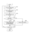
- Fig. 7 is a flowchart of a process to capture the image of a person according to the exemplary embodiment of the present invention.
- Fig. 8 is a flowchart of the process to capture the image of the person according to the exemplary embodiment of the present invention.
- Fig. 9 is a flowchart of a process to project an image according to the exemplary embodiment of the present invention.
- Figs. 1A to 1C are cross-sectional views of a remote communication system according to the present invention.
- communication can be performed between an office 1 disposed in a headquarter and an office 2 disposed on a branch A or between the office 1 and an office 3 disposed in a branch B.
- office 1 and the office 2 may be referred to as a "remote communication system”.
- remote communication system only the configuration included in a single office may be referred to as a "remote communication system”.
- the offices described herein may be separated so that the time required to move from one of the offices to the other is several hours, or the offices may be different conference rooms in the same building. That is, the term "remote" refers to physically different spaces and does not define the physical distance and the time length required for movement from one place to another.
- the office 1 illustrated in Fig. 1A has a projector 101, a background camera 102, a screen 103, front cameras 104, and a back camera 105 disposed therein.
- the projector 101 is a projection device that projects an image captured in any one of the other offices onto the screen 103.
- the screen 103 serves as a projection plane that displays the image projected by the projector 101.
- the screen 103 may be a screen temporarily placed when communication is performed with one of the other offices.
- a wall of the office may serve as the screen 103.
- the present exemplary embodiment is described with reference to an example in which the projector and the screen are used to display an image, the image may be displayed using a large liquid crystal display.
- the front cameras 104 are front image capturing devices for capturing the images of the person 106.
- three front cameras 104 that is, front cameras 104a, 104b, and 104c are employed.
- two front cameras or four or more front cameras may be employed. The process related to capturing the image of the person 106 using the front cameras 104 is described in more detail below.
- the background camera 102 is a background image capturing device that captures the background image of the person 106 (i.e., the image taken in the right direction in Fig. 1A).
- the office 1 is not a room dedicated to remote communication, but is an ordinary office room for everyday business.
- the background image captured by the background camera 102 contains the images of desks, chairs, and cabinets of employees and the image of a person who is conducting another business transaction. By projecting such a background image together with the image of the person captured by the front cameras 104, a simulated environment as if employees stood and chatted with one another in the corner of the office room can be produced. Note that to prevent the background image (an object) from being hidden by the image of the person 106, it is desirable that the background camera 102 be mounted on the upper section of the room in the vertical direction (near the ceiling).
- the back camera 105 is a back image capturing device for capturing the image of the person 106 or the image displayed on the screen 103 in the direction from the right to the left in Fig. 1A. Since the person 106 faces to the screen 103 (i.e., the left in Fig. 1A) during remote communication, the back camera 105 captures the image of the person 106 from behind. Note that the distance between the back camera 105 and the person 106 is longer than the distance between the front camera 104 and the person 106. Accordingly, the back camera 105 can capture the image of the entire body of the person 106.
- the front camera 104 includes a range sensor for detecting the distance from the front camera 104 to the subject.
- the image captured by the front camera 104 includes an RGB color image with 8 bits per channel and 3 channels and a range image with 8 bits per channel and 1 channel.
- each of the background camera 102 and the back camera 105 does not include a range sensor.
- an image captured by each of the background camera 102 and the back camera 105 includes an RGB color image with 8 bits per channel and 3 channels, but does not include a range image.
- the images captured by each of the front camera 104, the background camera 102, and the back camera 105 are time-series still images, which are sequentially projected in a remote site. In this manner, the images are played back in the form of a moving image.
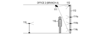
- a person 116 is located in the office 2 in which a person 116 is located (Fig. 1B), equipment similar to that in the office 1 (i.e., a projector 111, a background camera 112, a screen 113, a front camera 114, and a back camera 115) is provided in the office 3 in which a person 126 is located (Fig. 1C).
- equipment similar to that in the office 1 or 2 i.e., a projector 121, a background camera 122, a screen 123, a front camera 124, and a back camera 125
- each of the screens 103 and 113 measures 2.3 meters high by 4 meters wide.
- the screen 123 has a relatively smaller size and measures 1 meter high by 2 meters wide.
- the offices 1 and 2 each having a large screen need to be used.
- a small screen can be used as in the office 3.
- the image of the entire body of a person located in the remote site cannot be displayed on the screen 123.
- the image of only the upper body of the person is projected on the screen 123.
- Fig. 2 is an external view of the remote communication system viewed in a direction from the right to the left in Fig. 1A.
- the person 106 located in the office 1 is communicating with the person 116 located in the office 2.
- the screen 103 is horizontally long, two projectors 101 (i.e., projectors 101a and 101b) are provided. However, a single projector may project the image.
- the background camera 102 is set in the upper middle of the screen 103.
- the front cameras 104a, 104b, and 104c are embedded in the screen 103 so as to be arranged in a line in the middle section of the screen 103 in the vertical direction.
- a digitizer 201 is a detecting device that detects the operation performed on the screen 103 by a user.
- the digitizer 201 includes a transmitter 201a and a receiver 201b. If an infrared light beam projected by the transmitter 201a is blocked by, for example, part of the body of the person 106 or a pointer held by the person 106, the digitizer 201 outputs the coordinates of the position.
- the transmitter 201a and the receiver 201b are disposed at the left and right ends of the screen 103, respectively. However, the transmitter 201a and the receiver 201b may be disposed at the upper and lower ends of the screen 103, respectively.
- a technique for detecting the operation performed by a user is not limited to a technique using a digitizer.
- the screen 103 may have a touch panel function, and a position in the screen 103 at which the screen 103 is pressed may be detected.
- the image of the person 116 captured by the front camera 114 set in the office 2 is projected onto the screen 103.
- a document e.g., a conference material
- a document management server 340 (described below) is displayed as the background image of the person 116. It can be switched whether as the background of the person 116, a document stored in the document management server 340 is projected or the background image of the office 2 captured by the background camera 112 is projected in accordance with the operation performed by the person 116 and detected by the digitizer 201.
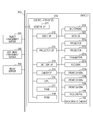
- Fig. 3 is a hardware configuration diagram of the remote communication system.
- a central processing unit (CPU) 316 included in a control apparatus 310 reads out a control program stored in a read only memory (ROM) 318 and controls the equipment provided in the office 1.
- a random access memory (RAM) 317 is used as temporary memory areas, such as a main memory and a work area of the CPU 316. Note that in the office 1, the CPU 316 uses a single memory (the RAM 317) and performs processes indicated by a flowchart described below. However, another form of processing can be employed.
- a control apparatus 310 may be provided for each of the cameras, projectors, and digitizer.
- the processes may be performed by a plurality of CPUs and RAMs (or hard disk drives (HDDs) or solid state drives (SSDs)) that are in cooperation with one another.
- some of the processes described below may be performed by a hardware circuit, such as an application specific integrated circuit (ASIC).
- ASIC application specific integrated circuit
- the offices are connected to one another using a network 300.
- Any network selected from among a wired network, a wireless network, a wide area network (WAN), a local area network (LAN), a public line, and a dedicated line can be employed as the network 300 in accordance with the environment.
- a network interface (I/F) 311 is employed to connect the office 1 to the network 300.
- Each of the offices has a microphone and a speaker disposed therein (not illustrated in Figs. 1A to 1C and Fig. 2).
- the speech emanated from a person in the office is converted into an audio signal by a microphone and is output from a speaker in a remote site.
- the office 1 has a microphone 319 and a speaker 320 disposed therein.
- an audio I/F 312 is employed to control the input of speech using the microphone 319 and the output of the speech using the speaker 320.
- a projector I/F 313 is employed to control projection of an image using the projector 101.
- a digitizer I/F 314 is employed to control detection of the operation performed by a user using the digitizer 201.
- a camera I/F 315 is employed to control the image capturing operations performed by the front camera 104, the back camera 105, and the background camera 102.
- each of the offices 2 and 3 has a configuration that is the same as that of the office 1 (not illustrated).
- Examples of the above-mentioned interfaces include a universal serial bus (USB), a high definition multimedia interface (HDMI (trade name)), a wired LAN, and a wireless LAN, one of which is selected as needed.
- a relay server 350 relays the image and speech.
- the document management server 340 stores documents to be projected onto the screen by the projector in each of the offices (e.g., a conference material).
- the CPU 316 upon receiving an instruction to project a document together with the image of the person, acquires the document from the document management server 340 and causes the projector 101 to project the document. Note that the instruction to project the document can be output from either one of the offices that perform remote communication.
- an object management server 330 stores objects to be projected onto the screen 103 by the projector 101.
- An example of the object is an operation button used to select one of the offices to be connected. If the remote communication system is started in the office 1, the CPU 316 acquires, from the object management server 330, selection buttons each corresponding to one of the offices and causes the projector 101 to project the selection buttons onto the screen 103. If the person 106 touches the screen 103, the digitizer 201 detects the coordinates of the touched position, and the CPU 316 identifies one of the selection buttons corresponding to the detected coordinates. Thereafter, the CPU 316 starts remote communication with the office corresponding to the identified selection button.
- Fig. 4 illustrates the image capturing areas of the front cameras 104.
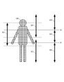
- the front cameras 104a, 104b, and 104c are set at heights of a (1800 mm), b (1300 mm), and c (500 mm) from the floor surface, respectively. That is, the arrangement interval between the front camera 104a and front camera 104b (500 mm) is shorter than the arrangement interval between the front camera 104b and front camera 104c (800 mm). In addition, the arrangement interval between the front camera 104b and front camera 104c (800 mm) is longer than the arrangement interval between the front camera 104c and the floor surface.
- each of the boundaries between the images is located at a position in the image of the person where the boundary is not prominent (in the vicinity of the chest and waist) when the images of the person are combined (described below, refer to Fig. 5 and Figs. 6A to 6F).
- the angles of view of the front cameras 104a, 104b, and 104c in the vertical direction are ⁇ a, ⁇ b, and ⁇ c, respectively. In this example, ⁇ a, ⁇ b, and ⁇ c are the same. However, the front cameras having different angles of view may be employed.
- a distance d from the front camera 104 to the person 106 is calculated on the basis of the range image captured by the front camera 104.
- a height h1 indicates a height of the middle point between the front camera 104b and the front camera 104c. The height h1 can be obtained by adding a height c of the front camera 104c to a length f, which is obtained by dividing the difference between the heights of the front camera 104b and the front camera 104c by 2.
- a height h2 indicates a height of the middle point between the front camera 104a and the front camera 104b.
- the height h2 can be obtained by adding a height b of the front camera 104b to a length obtained by dividing the difference between the heights of the front camera 104a and the front camera 104b by 2.
- a length e is a length corresponding to the difference between the highest position in the image of the person 106 captured by the front camera 104c and the height c of the front camera 104c.
- the length e can be obtained on the basis of an angle obtained by dividing ⁇ c by 2 and the distance d from the front camera 104 to the person 106.
- ranges 501, 502, and 503 indicate the ranges of the body of the person 106 captured by the front cameras 104a, 104b, and 104c, respectively.
- the range 501 captured by the front camera 104a partially overlaps the range 502 captured by the front camera 104b.
- the range 502 captured by the front camera 104b partially overlaps the range 503 captured by the front camera 104c.
- the overlapping portions are removed.
- the process is performed so that the boundaries are located at the height h1 and the height h2.
- the image captured by the front camera 104a is used as a range 504.
- the image captured by the front camera 104b is used as a range 505, and the image captured by the front camera 104c is used as a range 506.
- Figs. 6A, 6B, and 6C illustrate the images captured by the front cameras 104a, 104b, and 104c, respectively.
- the image in Fig. 6A corresponds to the range 501.
- the image used for projection in the remote site is the range 504
- a range corresponding to the difference between the range 501 and the range 504 is removed and, thus, the image illustrated in Fig. 6D is generated.
- the image in Fig. 6B corresponds to the range 502.
- the image used for projection in the remote site is the range 505
- a range corresponding to the difference between the range 502 and the range 505 is removed and, thus, the image illustrated in Fig. 6E is generated.
- a process to generate the image illustrated in Fig. 6F from the image illustrated in Fig. 6C is described in more detail below.
- the central point of the image illustrated in Fig. 6C corresponds to the height c at which the front camera 104c is disposed.
- the image above the central point corresponds to the range of the length e illustrated in Fig. 4.
- To remove, from the image in the range of the length e, the image in the range of the length g and leave the image in the range of the length f it is determined that from the pixels of the image captured by the front camera 104c arranged in the vertical direction (1080 pixels), the pixels equal in number to the ratio of the length g to the length e are to be removed.
- a portion to be removed is determined in the same manner.
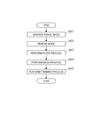
- Figs. 7 and 8 are flowcharts illustrating a process to capture the images of the person 106 using the front cameras 104 and a process to combine the images of the person captured by the front cameras 104.
- Each of operations (steps) indicated by the flowcharts in Figs. 7 and 8 is realized by the CPU 316 that is disposed in the office 1 and that executes a control program stored in the ROM 318.
- step S701 the value of a variable N is initialized to 1.
- step S702 among the front cameras 104a, 104b, and 104c, the CPU 316 instructs the front camera 104 corresponding to the variable N to capture the image of the person 106.
- step S703 the image of only the person 106 is generated from the image captured by the front camera 104.
- Fig. 8 is a flowchart illustrating the process performed in step S703 in detail.
- step S801 a range image included in the captured image obtained in step S702 is binarized.
- the person 106 stands at a position in the range from the position away from the screen 103 (the front camera 104) by 1 meter to the position away from the screen 103 by 2 meters.
- a minimum value of the distance from the front camera 104 to the subject is set to 1 meter
- the maximum value of the distance is set to 2 meters.
- the value of the pixel is changed to 255 if the value is within the above-described range.
- the values of the other pixels are set to 0.
- step S802 an erosion process that replaces the value of the pixel of interest with 0 under the condition that at least one pixel in the neighborhood is 0 or a dilation process that replaces the value of the pixel of interest with 255 under the condition that at least one pixel in the neighborhood is 255 is performed. In this manner, isolated point noise can be removed.
- step S803 a smoothing filter process (e.g., a Gaussian filter process) is performed to smooth the outline of an area where pixels each having a value of 255 are continuously arranged.
- a smoothing filter process e.g., a Gaussian filter process
- step S804 a mask process is performed.
- a pixel of the color image corresponding to a pixel of the range image having a value of 255 is made non-transparent, and a pixel of the color image corresponding to a pixel of the range image having a value of 0 is made fully transparent (is transparentized).
- the image of a person part is extracted from the image captured by the front camera 104.
- the term "person part” refers to not only the image of a person but the image of the person and, for example, a pointer or a product sample held by the person.
- step S805 as illustrated in Fig. 5 and Figs. 6A to 6F, a trimming process to trim the upper end or the lower end of an image is performed on the images of the person illustrated in Figs. 6A, 6B, and 6C to generate the images of the person illustrated in Figs. 6D, 6E, and 6F, respectively. More specifically, a predetermined area at the lower end is removed from the image illustrated in Fig. 6A. Predetermined areas at the upper end and the lower end are removed from the image illustrated in Fig. 6B. A predetermined area at the upper end is removed from the image illustrated in Fig. 6C.
- step S704 it is determined whether the value of the variable N is less than the number of the front cameras 104 (3 according to the present exemplary embodiment). If the value of the variable N is less than the number of the front cameras 104, the processing proceeds to step S705, where a value of 1 is added to the variable N. Thereafter, the processing returns to step S701. However, if the value of the variable N is not less than the number of the front cameras 104 (the value of the variable N is equal to the number of the front cameras 104), the processing proceeds to step S706.
- step S706 the images of the person illustrated in Figs. 6D, 6E, and 6F are combined. More specifically, the image illustrated in Fig. 6E is concatenated to the lower end of the image illustrated in Fig. 6D. In addition, the image illustrated in Fig. 6F is concatenated to the lower end of the above-described concatenated image. Furthermore, since after the concatenating process, a blank (a space above the head, a space on the left of the right hand, a space on the right of the left hand, and a space under the feet) is left in the concatenated image, the trimming process is performed on a rectangular area including the pixels each having a value of 255.
- step S707 the image obtained through the process performed in step S706 is transmitted to the office 2 that is connected to the office 1.
- step S708 it is determined whether an instruction to complete the remote communication is received. If an instruction to complete the remote communication is received, the processing is completed. However, if an instruction to complete the remote communication is not received, the processing returns to step S701. Thereafter, the processes in step S701 and the subsequent steps are performed again.
- steps S703 and S706 are performed on the image capturing side (the office in which a person representing the subject is located). However, the processes may be performed in the office on the projection side (the office in which the captured image is projected). In addition, the extraction process of the person part described in steps S802 to S804 may be performed after the combining process described in step S706. Furthermore, although description is not given in this example, the image captured by the background camera 102 and the image captured by the back camera 105 are transmitted to the office 2 that is connected to the office 1, synchronously or asynchronously with the transmission of the image performed in step S707.
- Fig. 9 is a flowchart of a process to project the image transmitted from an office connected to the office.
- Each of operations (steps) illustrated in Fig. 9 is realized by the CPU 316 that is disposed in the office 1 and that executes a control program stored in the ROM 318.
- the processes described with reference to Figs. 7 and 8 are performed in the office 2 by, for example, the CPU provided in the office 2 in the same manner, and the resultant images transmitted from the office 2 are projected in the office 1.
- step S901 the front image of a person captured by the front camera 114 is received.
- step S902 the back image of the person captured by the back camera 115 is received.
- step S903 the background image captured by the background camera 112 is received.
- step S904 it is determined whether an instruction to display the front image of the person is received or an instruction to display the back image of the person is received.
- the instructions are received in accordance with the operation performed by the person 106 and detected by the digitizer 201. If it is determined that an instruction to display the front image of the person is received, the processing proceeds to step S905, where the front image of the person received in step S901 and the background image received in step S903 are projected onto the screen 103. However, if it is determined that an instruction to display the back image of the person is received, the processing proceeds to step S906, where the back image of the person received in step S902 is projected onto the screen 103.
- step S907 it is determined whether an instruction to complete the remote communication is received. If it is determined that an instruction to complete the remote communication is received, the processing is completed. However, if it is determined that an instruction to complete the remote communication is not received, the processing returns to step S901. Thereafter, the processes in step S901 and the subsequent steps are performed again. Note that the processes in the flowchart illustrated in Fig. 7 and the processes in the flowchart illustrated in Fig. 9 are continuously and concurrently performed during remote communication.
- the remote communication system includes the projector 101 that projects, onto the screen 103, the image transmitted from the office 2 located in a remote site.
- the screen 103 has a plurality of the front cameras 104 disposed therein.
- the CPU 316 performs an extraction process that extracts a person part from each of the images captured by the front cameras 104 (refer to step S703) and a combining process that combines the plurality of images captured by the front cameras 104 (refer to step S706).
- the remote communication system includes the projector 111 that projects, onto the screen 113 disposed in the office 2, the image subjected to the extraction process and the combining process.
- the present invention can be achieved by performing the following processes. That is, the processes are providing a storage medium including software program code that realizes the functions of the above-described exemplary embodiment to a system or an apparatus and reading out the program code stored in the storage medium using a computer (a CPU or an MPU) in the system or the apparatus.
- a computer a CPU or an MPU
- the program code itself read from the storage medium realizes the functions of the above-described exemplary embodiment and, thus, the program code and the storage medium storing the program code constitutes the present invention.
- Embodiment(s) of the present invention can also be realized by a computer of a system or apparatus that reads out and executes computer executable instructions (e.g., one or more programs) recorded on a storage medium (which may also be referred to more fully as a 'non-transitory computer-readable storage medium') to perform the functions of one or more of the above-described embodiment(s) and/or that includes one or more circuits (e.g., application specific integrated circuit (ASIC)) for performing the functions of one or more of the above-described embodiment(s), and by a method performed by the computer of the system or apparatus by, for example, reading out and executing the computer executable instructions from the storage medium to perform the functions of one or more of the above-described embodiment(s) and/or controlling the one or more circuits to perform the functions of one or more of the above-described embodiment(s).
- computer executable instructions e.g., one or more programs
- a storage medium which may also be referred to more fully as
- the computer may comprise one or more processors (e.g., central processing unit (CPU), micro processing unit (MPU)) and may include a network of separate computers or separate processors to read out and execute the computer executable instructions.
- the computer executable instructions may be provided to the computer, for example, from a network or the storage medium.
- the storage medium may include, for example, one or more of a hard disk, a random-access memory (RAM), a read only memory (ROM), a storage of distributed computing systems, an optical disk (such as a compact disc (CD), digital versatile disc (DVD), or Blu-ray Disc (BD) TM ), a flash memory device, a memory card, and the like.
Landscapes
- Engineering & Computer Science (AREA)
- Multimedia (AREA)
- Signal Processing (AREA)
- Physics & Mathematics (AREA)
- General Physics & Mathematics (AREA)
- Theoretical Computer Science (AREA)
- Two-Way Televisions, Distribution Of Moving Picture Or The Like (AREA)
- Controls And Circuits For Display Device (AREA)
- Projection Apparatus (AREA)
- Image Processing (AREA)
- Studio Devices (AREA)
Abstract
La présente invention concerne un schéma qui permet à une personne de communiquer avec une autre personne sur un site distant tout en donnant la sensation réaliste que les personnes se font face de façon très proche en capturant les images de la personne grâce à une pluralité d'unités de capture d'image. Un système de communication à distance comprend un projecteur configuré pour projeter, sur un écran, une image transmise depuis un site distant. L'écran comporte une pluralité des caméras frontales disposée sur celui-ci. Une CPU effectue un processus d'extraction pour extraire une partie d'une personne de chacune des images capturées par les caméras frontales et un processus de combinaison servant à combiner les images capturées par les caméras frontales. Le système de communication à distance comprend aussi un projecteur qui projette l'image soumise au processus d'extraction et au processus de combinaison sur un écran installé sur le site distant.
Priority Applications (1)
| Application Number | Priority Date | Filing Date | Title |
|---|---|---|---|
| US15/572,127 US10178347B2 (en) | 2015-05-08 | 2016-03-30 | Remote communication system, method for controlling remote communication system, and program |
Applications Claiming Priority (2)
| Application Number | Priority Date | Filing Date | Title |
|---|---|---|---|
| JP2015095885A JP6700672B2 (ja) | 2015-05-08 | 2015-05-08 | 遠隔コミュニケーションシステム、その制御方法、及びプログラム |
| JP2015-095885 | 2015-05-08 |
Publications (1)
| Publication Number | Publication Date |
|---|---|
| WO2016181599A1 true WO2016181599A1 (fr) | 2016-11-17 |
Family
ID=57247836
Family Applications (1)
| Application Number | Title | Priority Date | Filing Date |
|---|---|---|---|
| PCT/JP2016/001842 Ceased WO2016181599A1 (fr) | 2015-05-08 | 2016-03-30 | Système de communication à distance, procédé de commande de système de communication à distance, et programme |
Country Status (3)
| Country | Link |
|---|---|
| US (1) | US10178347B2 (fr) |
| JP (1) | JP6700672B2 (fr) |
| WO (1) | WO2016181599A1 (fr) |
Families Citing this family (2)
| Publication number | Priority date | Publication date | Assignee | Title |
|---|---|---|---|---|
| JP6432118B2 (ja) | 2016-10-31 | 2018-12-05 | Thk株式会社 | レンズ移動機構 |
| CN109040643B (zh) * | 2018-07-18 | 2021-04-20 | 奇酷互联网络科技(深圳)有限公司 | 移动终端及远程合影的方法、装置 |
Citations (2)
| Publication number | Priority date | Publication date | Assignee | Title |
|---|---|---|---|---|
| JPH07154777A (ja) * | 1993-11-30 | 1995-06-16 | Matsushita Electric Ind Co Ltd | 画像処理装置およびテレビ電話装置 |
| US5990932A (en) * | 1997-12-22 | 1999-11-23 | Northern Telecom, Limited | Collaborative shared space |
Family Cites Families (15)
| Publication number | Priority date | Publication date | Assignee | Title |
|---|---|---|---|---|
| JP4507571B2 (ja) * | 2003-11-25 | 2010-07-21 | パナソニック電工株式会社 | 人体姿勢計測装置 |
| US7932919B2 (en) * | 2006-04-21 | 2011-04-26 | Dell Products L.P. | Virtual ring camera |
| JP2008191613A (ja) | 2007-02-08 | 2008-08-21 | Dainippon Printing Co Ltd | 遠隔会議システム |
| US7911513B2 (en) * | 2007-04-20 | 2011-03-22 | General Instrument Corporation | Simulating short depth of field to maximize privacy in videotelephony |
| US8164617B2 (en) * | 2009-03-25 | 2012-04-24 | Cisco Technology, Inc. | Combining views of a plurality of cameras for a video conferencing endpoint with a display wall |
| US8908008B2 (en) * | 2010-07-16 | 2014-12-09 | Hewlett-Packard Development Company, L.P. | Methods and systems for establishing eye contact and accurate gaze in remote collaboration |
| US8896655B2 (en) * | 2010-08-31 | 2014-11-25 | Cisco Technology, Inc. | System and method for providing depth adaptive video conferencing |
| US9055189B2 (en) * | 2010-12-16 | 2015-06-09 | Microsoft Technology Licensing, Llc | Virtual circular conferencing experience using unified communication technology |
| NO333184B1 (no) * | 2011-08-31 | 2013-03-25 | Cisco Tech Inc | Metode og anordning for samarbeidende representasjon i videokonferanser |
| US9232183B2 (en) * | 2013-04-19 | 2016-01-05 | At&T Intellectual Property I, Lp | System and method for providing separate communication zones in a large format videoconference |
| US9282285B2 (en) * | 2013-06-10 | 2016-03-08 | Citrix Systems, Inc. | Providing user video having a virtual curtain to an online conference |
| US9055186B2 (en) * | 2013-07-23 | 2015-06-09 | Personify, Inc | Systems and methods for integrating user personas with content during video conferencing |
| US9449414B1 (en) * | 2015-03-05 | 2016-09-20 | Microsoft Technology Licensing, Llc | Collaborative presentation system |
| JP6461679B2 (ja) * | 2015-03-31 | 2019-01-30 | 大和ハウス工業株式会社 | 映像表示システム及び映像表示方法 |
| JP2016213677A (ja) * | 2015-05-08 | 2016-12-15 | キヤノン株式会社 | 遠隔コミュニケーションシステム、その制御方法、及びプログラム |
-
2015
- 2015-05-08 JP JP2015095885A patent/JP6700672B2/ja active Active
-
2016
- 2016-03-30 WO PCT/JP2016/001842 patent/WO2016181599A1/fr not_active Ceased
- 2016-03-30 US US15/572,127 patent/US10178347B2/en active Active
Patent Citations (2)
| Publication number | Priority date | Publication date | Assignee | Title |
|---|---|---|---|---|
| JPH07154777A (ja) * | 1993-11-30 | 1995-06-16 | Matsushita Electric Ind Co Ltd | 画像処理装置およびテレビ電話装置 |
| US5990932A (en) * | 1997-12-22 | 1999-11-23 | Northern Telecom, Limited | Collaborative shared space |
Non-Patent Citations (3)
| Title |
|---|
| ICHIKAWA, Y. ET AL.: "MAJIC Videoconferencing System: Experiments, Evaluation and Improvement", PROCEEDINGS OF THE FOURTH EUROPEAN CONFERENCE ON COMPUTER-SUPPORTED COOPERATIVE WORK, pages 279 - 292, XP055328481, Retrieved from the Internet <URL:http://www.ecscw.uni-siegen.de/1995/18.pdf> * |
| WU WEIGUO ET AL.: "2006-0011 Background generating system at the region-based virtual viewpoint image generation", SONY KOKAI GIHOSHU (SONY JOURNAL OF TECHNICAL DISCLOSURE, vol. 15, no. 1, pages 1 - 15, ISSN: 0918-9955 * |
| ZILLNER, J. ET AL.: "3D-Board: A Whole-body Remote Collaborative Whiteboard", PROCEEDINGS OF THE 27TH ANNUAL ACM SYMPOSIUM ON USER INTERFACE SOFTWARE AND TECHNOLOGY (UIST '14), 8 October 2014 (2014-10-08), pages 471 - 479, XP058058550, Retrieved from the Internet <URL:http://citeseerx.ist.psu.edu/viewdoc/download?doi=10.1.1.655.9165&rep=repl&type=pdf> [retrieved on 20160603] * |
Also Published As
| Publication number | Publication date |
|---|---|
| JP2016213675A (ja) | 2016-12-15 |
| JP6700672B2 (ja) | 2020-05-27 |
| US10178347B2 (en) | 2019-01-08 |
| US20180139409A1 (en) | 2018-05-17 |
Similar Documents
| Publication | Publication Date | Title |
|---|---|---|
| US9900568B2 (en) | Remote communication system, method for controlling remote communication system, and storage medium | |
| CN101874234B (zh) | 用户接口装置、用户接口方法、以及记录媒体 | |
| US9055190B2 (en) | Arrangement of multiple audiovisual streams | |
| EP3143477B1 (fr) | Système et procédé pour fournir une rétroaction haptique pour aider à la capture d'images | |
| US20130335573A1 (en) | Input method designed for augmented reality goggles | |
| US10600218B2 (en) | Display control system, display control apparatus, display control method, and storage medium | |
| US11589001B2 (en) | Information processing apparatus, information processing method, and program | |
| WO2015159548A1 (fr) | Dispositif et procédé de commande de projection ainsi que support d'enregistrement permettant l'enregistrement d'un programme de commande de projection | |
| KR102082661B1 (ko) | 전자 장치의 촬영 이미지 생성 방법 및 장치 | |
| JP2017033256A (ja) | 画像処理装置、コミュニケーションシステム、画像処理方法、及びプログラム | |
| US10178347B2 (en) | Remote communication system, method for controlling remote communication system, and program | |
| US10122964B2 (en) | Communication system | |
| Pauchet et al. | TableTops: Worthwhile experiences of collocated and remote collaboration | |
| KR101405439B1 (ko) | 동작인식 배경영상 제공시스템, 동작인식 배경영상 제공방법 및 그 기록매체 | |
| US9854204B2 (en) | Communication system and method for controlling the same | |
| KR102640871B1 (ko) | 증강 현실을 이용한 영상 데이터를 제공하는 전자 장치 및 그 제어 방법 | |
| KR101268640B1 (ko) | 대형 스크린을 위한 디스플레이 시스템 및 그 시스템의 동작 방법 | |
| JP2021060789A (ja) | 映像処理システム | |
| JP6170457B2 (ja) | プレゼンテーション管理装置およびプレゼンテーション管理プログラム | |
| JP2017032757A (ja) | 表示制御装置、表示制御方法、表示制御システム、及び、プログラム | |
| KR20180033738A (ko) | 디스플레이 장치에 설치되는 착탈식 터치 패널 장치 | |
| CN116916083A (zh) | 视频处理方法、显示方法、系统及相关设备 | |
| CN103198763A (zh) | 一种动态佛龛的实现方法 | |
| JP2020013584A (ja) | 仮想現実表示システム、仮想現実表示方法及びコンピュータプログラム | |
| Premaratne | Sixth Sense Based Human Computer Interaction System for Projected Screen |
Legal Events
| Date | Code | Title | Description |
|---|---|---|---|
| 121 | Ep: the epo has been informed by wipo that ep was designated in this application |
Ref document number: 16792334 Country of ref document: EP Kind code of ref document: A1 |
|
| WWE | Wipo information: entry into national phase |
Ref document number: 15572127 Country of ref document: US |
|
| NENP | Non-entry into the national phase |
Ref country code: DE |
|
| 122 | Ep: pct application non-entry in european phase |
Ref document number: 16792334 Country of ref document: EP Kind code of ref document: A1 |