WO2016181604A1 - Système de gestion de bétail, dispositif capteur, et procédé d'estimation d'état de bétail - Google Patents
Système de gestion de bétail, dispositif capteur, et procédé d'estimation d'état de bétail Download PDFInfo
- Publication number
- WO2016181604A1 WO2016181604A1 PCT/JP2016/001922 JP2016001922W WO2016181604A1 WO 2016181604 A1 WO2016181604 A1 WO 2016181604A1 JP 2016001922 W JP2016001922 W JP 2016001922W WO 2016181604 A1 WO2016181604 A1 WO 2016181604A1
- Authority
- WO
- WIPO (PCT)
- Prior art keywords
- livestock
- power generation
- management system
- state
- unit
- Prior art date
- Legal status (The legal status is an assumption and is not a legal conclusion. Google has not performed a legal analysis and makes no representation as to the accuracy of the status listed.)
- Ceased
Links
- XDTMQSROBMDMFD-UHFFFAOYSA-N C1CCCCC1 Chemical compound C1CCCCC1 XDTMQSROBMDMFD-UHFFFAOYSA-N 0.000 description 2
Images











Classifications
-
- A—HUMAN NECESSITIES
- A01—AGRICULTURE; FORESTRY; ANIMAL HUSBANDRY; HUNTING; TRAPPING; FISHING
- A01K—ANIMAL HUSBANDRY; AVICULTURE; APICULTURE; PISCICULTURE; FISHING; REARING OR BREEDING ANIMALS, NOT OTHERWISE PROVIDED FOR; NEW BREEDS OF ANIMALS
- A01K29/00—Other apparatus for animal husbandry
- A01K29/005—Monitoring or measuring activity
-
- A—HUMAN NECESSITIES
- A01—AGRICULTURE; FORESTRY; ANIMAL HUSBANDRY; HUNTING; TRAPPING; FISHING
- A01K—ANIMAL HUSBANDRY; AVICULTURE; APICULTURE; PISCICULTURE; FISHING; REARING OR BREEDING ANIMALS, NOT OTHERWISE PROVIDED FOR; NEW BREEDS OF ANIMALS
- A01K11/00—Marking of animals
- A01K11/001—Ear-tags
- A01K11/004—Ear-tags with electronic identification means, e.g. transponders
-
- A—HUMAN NECESSITIES
- A01—AGRICULTURE; FORESTRY; ANIMAL HUSBANDRY; HUNTING; TRAPPING; FISHING
- A01K—ANIMAL HUSBANDRY; AVICULTURE; APICULTURE; PISCICULTURE; FISHING; REARING OR BREEDING ANIMALS, NOT OTHERWISE PROVIDED FOR; NEW BREEDS OF ANIMALS
- A01K11/00—Marking of animals
- A01K11/006—Automatic identification systems for animals, e.g. electronic devices, transponders for animals
-
- A—HUMAN NECESSITIES
- A01—AGRICULTURE; FORESTRY; ANIMAL HUSBANDRY; HUNTING; TRAPPING; FISHING
- A01K—ANIMAL HUSBANDRY; AVICULTURE; APICULTURE; PISCICULTURE; FISHING; REARING OR BREEDING ANIMALS, NOT OTHERWISE PROVIDED FOR; NEW BREEDS OF ANIMALS
- A01K11/00—Marking of animals
- A01K11/006—Automatic identification systems for animals, e.g. electronic devices, transponders for animals
- A01K11/008—Automatic identification systems for animals, e.g. electronic devices, transponders for animals incorporating global positioning system [GPS]
-
- G—PHYSICS
- G06—COMPUTING OR CALCULATING; COUNTING
- G06K—GRAPHICAL DATA READING; PRESENTATION OF DATA; RECORD CARRIERS; HANDLING RECORD CARRIERS
- G06K17/00—Methods or arrangements for effecting co-operative working between equipments covered by two or more of main groups G06K1/00 - G06K15/00, e.g. automatic card files incorporating conveying and reading operations
- G06K17/0022—Methods or arrangements for effecting co-operative working between equipments covered by two or more of main groups G06K1/00 - G06K15/00, e.g. automatic card files incorporating conveying and reading operations arrangements or provisions for transferring data to distant stations, e.g. from a sensing device
- G06K17/0029—Methods or arrangements for effecting co-operative working between equipments covered by two or more of main groups G06K1/00 - G06K15/00, e.g. automatic card files incorporating conveying and reading operations arrangements or provisions for transferring data to distant stations, e.g. from a sensing device the arrangement being specially adapted for wireless interrogation of grouped or bundled articles tagged with wireless record carriers
-
- G—PHYSICS
- G06—COMPUTING OR CALCULATING; COUNTING
- G06Q—INFORMATION AND COMMUNICATION TECHNOLOGY [ICT] SPECIALLY ADAPTED FOR ADMINISTRATIVE, COMMERCIAL, FINANCIAL, MANAGERIAL OR SUPERVISORY PURPOSES; SYSTEMS OR METHODS SPECIALLY ADAPTED FOR ADMINISTRATIVE, COMMERCIAL, FINANCIAL, MANAGERIAL OR SUPERVISORY PURPOSES, NOT OTHERWISE PROVIDED FOR
- G06Q50/00—Information and communication technology [ICT] specially adapted for implementation of business processes of specific business sectors, e.g. utilities or tourism
- G06Q50/02—Agriculture; Fishing; Forestry; Mining
Definitions
- This technology relates to a livestock management system, a sensor device, and a livestock state estimation method.
- Patent Document 1 describes a livestock / poultry breeding management system capable of analyzing livestock growth data and environmental data to predict meat quality.
- Patent Document 2 describes a technique for predicting meat quality in a living body by statistically grasping the correlation between bovine bioimpedance and meat quality and measuring the bovine bioimpedance.
- Patent Document 1 cannot predict meat quality based on information on individual livestock or poultry, and has a problem in terms of prediction accuracy.
- the technique described in Patent Document 2 needs to measure the bioimpedance of individual livestock, and is particularly burdensome for large-scale farmers.
- an object of the present technology is to provide a livestock management system, a sensor device, and a livestock state estimation method capable of easily and accurately estimating the livestock state.
- a livestock management system includes a management device.
- the management device includes a power generation unit that generates power according to the surrounding environment, and a transmission unit that transmits power generation information of the power generation unit using power obtained by the power generation unit, and is attached to livestock.
- a receiving unit that receives the power generation information from a sensor device that is configured to be capable of transmitting, and a control unit that estimates the state of the livestock based on the power generation information.
- a sensor device includes a housing, a power generation unit, and a control unit.
- the power generation unit is housed in the housing and generates electric power according to the surrounding environment.
- the said control part is accommodated in the said housing
- the estimation method of the state of livestock is as follows:
- the control unit of the information processing device receives the power generation information of the power generation unit from a sensor device that has a power generation unit that generates power according to the surrounding environment and is attached to livestock, And a step of estimating the state of the livestock based on the power generation information.
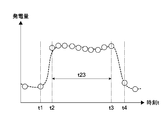
- FIG. 10 is a graph for explaining an example of processing using a temperature difference generator according to Modification 1-5.
- 12 is a flowchart showing a flow of processing for setting a state estimation algorithm based on an estimation state according to Modification 1-5.
- It is a block diagram which shows the structure of the said livestock management system which concerns on the modification 1-6.
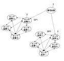
- FIG. 10 is a schematic diagram showing a concept of Modification 1-7. It is a block diagram which shows the structure of the livestock management system of 2nd Embodiment. It is a block diagram which shows the structure of the livestock management system of 3rd Embodiment.
- FIG. 1 is a schematic diagram illustrating a schematic configuration of a livestock management system according to a first embodiment of the present technology.
- the livestock management system 100 includes a plurality of sensor devices 1, a communication device 2, and a management device 3.
- the livestock management system 100 is a system introduced into a livestock facility, for example, so that the management device 3 can acquire predetermined information from the sensor device 1 attached to each livestock A and estimate the state of the livestock A. Composed.
- livestock include industrial animals such as beef cattle, dairy cows, pigs, horses, sheep, goats, poultry, and pet animals such as dogs, cats and rabbits. Examples of beef cattle are shown below.
- the livestock facility is not particularly limited as long as it can accommodate the above livestock, but in the following, an example of a facility provided with a barn that can accommodate livestock and a grazing farm that can graze livestock will be described.
- each of the plurality of sensor devices 1 can be attached to a plurality of livestock A, for example, attached to the ears of the livestock A, respectively.
- the receiving position is not limited to the ears, and attachment to other than the ears such as the neck, back and feet is also possible.
- attachment to the ear is preferable to the neck or foot.
- the communication device 2 receives the information transmitted from the sensor device 1 and transmits the received information to the management device 3 on the network N.
- the network N can be, for example, the Internet or a local area network.
- the communication device 2 may be attached to a gate 42 of a livestock facility, for example.
- the management device 3 is a server device on the network N, and receives predetermined information from the sensor device 1 transmitted from the communication device 2.
- the management device 3 is configured as an information processing device, for example.
- the livestock management system 100 may be further connected to the master monitor device 41 of the livestock system 4 introduced into the livestock facility via the network N.
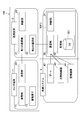
- FIG. 2 is a block diagram showing a configuration of each device included in the livestock management system 100. The configuration of each device will be described with reference to FIG.
- the sensor device 1 includes a power generation unit 11, a power storage element 12, and an output unit (transmission unit) 13.
- the power generation unit 11 is a generator that generates electric power according to the surrounding environment.
- the power generation unit 11 is, for example, a solar cell that generates power using energy based on at least one of light, heat, vibration, a radio wave including a far electromagnetic field and a near electromagnetic field, and a specific organic substance and an inorganic substance. Also good.
- the power generation method may be any of electrostatic type, electromagnetic type, inverse magnetostrictive type, piezoelectric type and the like.
- the power generation unit 11 may generate power using light (for example, an indoor light bulb or sunlight).
- the power generation unit 11 may be a thermoelectric conversion element that generates power using a temperature difference (heat) (for example, a power generation by the Seebeck effect or the Thomson effect, a thermoelectric power generation element, or a thermomagnetic power generation). Such a power generation unit 11 generates power using, for example, the temperature difference between the body temperature of the livestock and the outside air temperature.
- the power generation unit 11 may be an enzyme battery (also referred to as a bio battery) that generates power using sugar.
- the power generation unit 11 uses any one of LCR (inductance, capacitance, reactance) components, or a combination thereof, and capacitive coupling or electromagnetic coupling by a capacitor, a capacitor, an antenna, a rectenna, and the like. It may be a thing.
- the power generation unit 11 may perform near electromagnetic field power generation, that is, generate power using energy obtained by bringing the sensor device close to a predetermined device.
- a known method such as a magnetic field resonance method, an electromagnetic induction method, an electric field coupling method, an electric field resonance method, or the like can be applied.
- known power generation elements other than those illustrated can be applied.
- the electricity storage element 12 is used according to the purpose such as storing the electric power generated by the power generation unit 11.
- the electric power generated by the power generation unit 11 is stored in the power storage element 12 and used as electric power for operating the transmission unit 13.
- the storage element 12 includes various secondary batteries such as lithium ion secondary batteries, electric double layer capacitors, lithium ion capacitors, polyacenic organic semiconductor (PAS) capacitors, nanogate capacitors (“Nanogate”).
- PES polyacenic organic semiconductor
- Nanogate nanogate capacitors
- a combination of these power storage elements may be used.
- the sensor device 1 is attached to livestock, it is assumed that the sensor device 1 is used in a cold area outdoors.
- the power storage element 12 is composed of a capacitor such as a ceramic capacitor, because sufficient power storage is possible even at a low temperature, and problems such as a decrease in power storage efficiency and inability to store power are unlikely to occur.
- the storage element 12 is constituted by a capacitor such as a ceramic capacitor, the sensor device can be used even in an environment of less than 0 degrees Celsius (for example, in a cold region where the environmental temperature is minus 11 degrees Celsius or minus 21 degrees Celsius when raising cattle). 1 can store the power generated by the power generation unit 11 in a power storage element 12 configured by a capacitor, and can transmit power generation information from the transmission unit 13 using the stored power.
- the transmission unit 13 transmits the power generation information of the power generation unit 11 using the power obtained by the power generation unit 11.
- the transmission unit 13 is configured to be able to be switched between a standby state and a transmission state in which power generation information can be transmitted according to the power supplied from the power generation unit.
- the predetermined information can be transmitted as power generation information indicating the fact of power generation exceeding the predetermined amount.
- you may include the information of the value which shows the electric power generation amount by the electric power generation part 11 in the electric power generation information to transmit.
- the transmission unit 13 includes, for example, an integrated circuit (IC) composed of one element or a plurality of elements, a processor that controls transmission, and a communication circuit and an antenna for performing communication with the communication device 2.
- IC integrated circuit
- Examples of the integrated circuit used in the transmission unit 13 include switching elements such as transistors, diodes, reset ICs, regulator ICs, logic ICs, and various arithmetic circuits.
- the circuit configuration inside the IC can be appropriately changed as long as the function of the transmission unit 13 can be realized.
- the transmission unit 13 preferably has a configuration capable of storing the state by holding the state after the transition, but may have a configuration in which the state cannot be stored due to a reset or the like and cannot be stored.
- a reset IC is used as the integrated circuit of the transmission unit 13. Further, the power generated in the power generation unit 11 may be supplied to the transmission unit 13 after being stepped up or down as appropriate.
- the processor used for the transmission unit 13 executes control on the communication circuit. Examples of the processor include an MPU (Micro Processing Unit) and a CPU (Central Processing Unit). As the processor, MPU is more preferable because of the processing amount of the transmission unit 13 and the request for downsizing of the sensor device 1.
- the communication performed by the communication circuit of the transmission unit 13 may be wireless or wired. Further, a single wireless circuit may be used, a plurality of types may be used, or a plurality of types of composite circuits may be used.
- Wireless communication may be communication using electromagnetic waves (including infrared rays) or communication using electric fields. Specific methods include “Wi-Fi (registered trademark)”, “Zigbee (registered trademark)”, “Bluetooth (registered trademark)”, “Bluetooth Low Energy”, “ANT (registered trademark)”, “ANT + ( Examples of the communication method using a band of several hundred MHz (megahertz) to several GHz (gigahertz), such as “registered trademark” and “EnOcean (registered trademark)”. Near field communication such as NFC (Near Field Communication) may be used.
- NFC Near Field Communication
- the transmission unit 13 may transmit an identifier (ID (Identifier)) assigned to the power generation unit 11 as power generation information in the transmission state.
- ID Identifier
- the identifier may be assigned to each power generation unit 11 of the sensor device 1 or may be assigned to each module described later.
- the identifier may be a pre-assigned identifier or an assigned identifier each time. For example, when the sensor apparatus 1 establishes a communication connection with another device, an identifier may be assigned to each module, and the assigned identifier may be used. Since the identifier is set corresponding to the sensor device 1 attached to the livestock or the power generation unit 11 and the circuit included in the sensor device 1 in this way, the livestock can be identified by the identifier.
- the communication device 2 can communicate with each of the transmission unit 13 and the communication unit 33 and is configured to be able to transmit the power generation information transmitted from the transmission unit 13 to the communication unit 33.
- the configuration is capable of communicating with a plurality of sensor devices.
- the communication device 2 includes a first communication unit 21, a second communication unit 22, and a control unit 23.
- the first communication unit 21 is configured to be able to communicate with the transmission unit 13 of the sensor device 1.
- the first communication unit 21 includes a communication circuit and an antenna for performing communication with the transmission unit 13.
- the first communication unit 21 has a configuration capable of wireless communication such as communication using electromagnetic waves (including infrared rays), communication using electric fields, and wired communication.
- the second communication unit 22 is connected to the network N and configured to be able to communicate with the management device 3.
- the second communication unit 22 includes a communication circuit and an antenna for connecting to the network N and performing communication.
- the second communication unit 22 is connected to the network N using a wireless LAN (IEEE802.11 or the like) such as WiFi (Wireless Fidelity) or a 3G or 4G network for mobile communication, and the management device 3 can communicate.
- the control unit 23 controls the first communication unit 21 and the second communication unit 22 and is realized by a CPU, for example.
- the communication device 2 may further include a storage unit such as a CPU, a RAM, and a ROM (not shown).
- the management device 3 includes a CPU (control unit) 31, a storage unit 32, and a communication unit 33.
- the management device 3 may be configured by one or a plurality of servers.
- CPU31 functions as a control part of management device 3, and presumes the state of livestock based on power generation information.
- the storage unit 32 includes, for example, a ROM that stores a program that is executed by the CPU 31 and a RAM that is used as a work memory or the like when the CPU 31 executes processing.
- the storage unit 32 may include a nonvolatile memory such as an HDD (Hard Disk Drive) and a flash memory (SSD; Solid State Drive). Thereby, the memory
- HDD Hard Disk Drive
- SSD Solid State Drive
- the communication unit 33 is configured to connect to the Internet N and communicate with the communication device 2 and the livestock system 4.
- the communication unit 33 functions as a “reception unit”.
- the communication unit 33 is for wired communication using a NIC (Network Interface Card) for Ethernet (registered trademark), a wireless LAN (IEEE802.11 or the like) such as WiFi (Wireless Fidelity), or mobile communication.
- NIC Network Interface Card
- IEEE802.11 or the like such as WiFi (Wireless Fidelity)
- mobile communication Wireless communication using a 3G or 4G network.
- the management apparatus 3 may have a configuration such as an input device, a display device, a speaker, or the like as necessary, although not illustrated.
- the management device 3 is connected to the livestock system 4.
- the livestock system 4 includes, for example, a master monitor device 41, a plurality of gates 42 provided in the livestock facility, an automatic feeder 43, various monitoring devices 44, and the like.
- the master monitor device 41 acquires information processed by the management device 3 via the network N, and controls each device provided in the livestock facility based on this information.
- the master monitor device 41 may acquire the information by receiving information from the management device 3 through a communication circuit, for example, or by reading the information once stored in a recording medium such as a memory. The above information may be acquired.
- the master monitor device 41 is typically configured by an information processing device such as a PC (Personal Computer), a smartphone, or a tablet terminal.
- the master monitor device 41 includes a control unit configured by a CPU, a storage unit including a ROM, a RAM, and other memories, a communication unit including a communication circuit and an antenna, a liquid crystal display and an OLED (Organic). And a display unit including a display such as a light emitting diode.
- the gate 42 is a gate that partitions, for example, a barn and a grazing field, and has a drive mechanism for performing opening and closing, although not shown. The gate 42 is controlled to be opened and closed by controlling the drive mechanism by the master monitor device 41.
- the communication device 2 may be disposed on at least one of the plurality of gates 42.
- the automatic feeder 43 is a device for automatically providing feed to livestock, and has a feed tank, a feeder for feeding, a transport mechanism for transporting feed from the tank to the feeder, and the like (not shown).
- the feed timing of feed, the amount of feed, the mixing ratio of two or more types of feed, and the like are controlled by the master monitor device 41.
- the monitoring device 44 is a device arranged at a predetermined location in the livestock facility, and includes, for example, a monitoring camera or an infrared sensor. The monitoring device 44 monitors the state of livestock, the situation of livestock facilities, and the like, and transmits the acquired information to the master monitor device 41.
- the livestock system 4 may have an air conditioning facility of a livestock facility, a lighting device, or the like as necessary.
- FIG. 3 is a diagram illustrating an example of the appearance of the sensor device 1.
- the sensor device 1 further includes a housing 14 that houses the power generation unit 11 and the transmission unit 13.
- the housing 14 may further accommodate the above-described power storage element 12 and may accommodate all the modules described below.
- the electric power generation part 11, the electrical storage element 12, and the transmission part 13 which are shown to the same figure have shown typically that these elements are accommodated in the sensor apparatus 1.
- FIG. The housing 14 has, for example, a mounting hole 141 and is configured to be mounted on the livestock A through the hole 141 as shown in FIG.
- the housing 14 may be mounted, for example, in the vicinity of the ear tag for individual identification.
- the housing 14 may have a mounting mechanism for mounting on livestock, and the housing 14 may be mounted via a member having another mounting mechanism.
- the casing 14 is made of, for example, a resin material such as ABS resin, polycarbonate resin, polylactic acid, or polyamide resin, and at least a part thereof is made of a translucent material that can transmit sunlight. Good.
- a material for the housing 14 a material containing plant-derived materials, a material having antiallergic properties, a material having antibacterial properties, and the like can be appropriately selected in consideration of safety to the environment and a living body. .
- the sensor device 1 does not have a structure such as a lid for replacing the storage element 12 such as a battery or a connector for connecting to an external device.
- casing 14 can be made into the airtight structure which can suppress the permeation of the gas and liquid from the outside.
- the entire housing 14 can be integrally formed.
- the sensor device 1 can be configured to have high water resistance, dust resistance, impact resistance, and corrosion resistance. Thereby, it is possible to provide the sensor device 1 having high durability even in a livestock rearing environment that is apt to be affected by excrement, weather, feed, dust, and collision between livestock.
- FIG. 4 is a block diagram illustrating an example of the sensor device 1 according to the present embodiment.
- the sensor device 1 has, for example, one or a plurality of modules. As shown in the figure, the sensor device 1 has, for example, four modules (module 10a, module 10b, module 10c, and module 10d). Each module includes, for example, the above-described power generation unit 11, power storage element 12, and transmission unit 13.
- the module 10 a includes a solar power generation unit 11 a that generates power using irradiated sunlight as an example of a power generation unit. Furthermore, the module 10a includes a power storage element 12a connected to the solar power generation unit 11a and a transmission unit 13a connected to the power storage element 12a.
- the module 10b includes a temperature difference power generation unit 11b that generates power using a temperature difference as an example of a power generation unit. Further, the module 10b includes a power storage element 12b connected to the temperature difference power generation unit 11b and a transmission unit 13b connected to the power storage element 12b.
- the module 10c includes a vibration power generation unit 11c that generates power in response to vibration as an example of a power generation unit.
- the module 10c includes a power storage element 12c connected to the vibration power generation unit 11c and a transmission unit 13c connected to the power storage element 12c.
- the module 10d includes a radio power generation unit 11d that generates power using radio waves as an example of a power generation unit.
- the module 10d includes a power storage element 12d connected to the radio wave power generation unit 11d and a transmission unit 13d connected to the power storage element 12d.
- a transmission unit is provided for each power generation unit.
- FIG. 5 is a diagram illustrating an example of a specific configuration of the module 10a.
- the module 10a includes, for example, a power generation unit 11, a regulator IC 101, a charger 102, a secondary battery 103, a capacitor 104, a capacitor 105, a reset IC 106, an MPU 107, a storage unit 108, and a communication circuit 109. It has the composition which contains.
- the storage unit 108 includes, for example, a ROM (Read Only Memory) 108a and a RAM (Random Access Memory) 108b.
- the power generation unit 11 in the case of the module 10a is the solar power generation unit 11a made of a solar cell.
- the power generated by the power generation unit 11 is supplied to the regulator IC 101.
- the regulator IC 101 raises or lowers the input voltage to make the output voltage constant. Whether the regulator IC 101 performs step-up or step-down depends on the configuration of the power generation unit 11.
- the output voltage of the regulator IC 101 is supplied to the charger 102.
- the charger 102 is a circuit that charges the secondary battery 103 using the power supplied from the regulator IC 101. Note that the charger 102 may control the discharge of the secondary battery 103. The charger 102 may monitor whether or not the secondary battery 103 is abnormal. The secondary battery 103 is charged in accordance with the charging control by the charger 102.
- the secondary battery 103 is a rechargeable battery.
- An example of the secondary battery 103 is a lithium ion secondary battery. Of course, other secondary batteries may be used. Since the capacity of the secondary battery 103 may be, for example, about several tens of ⁇ Wh (microwatt hour) or several mWh (milliwatt hour), the secondary battery 103 does not increase in size.
- the output voltage of the secondary battery 103 is supplied to the capacitor 104 and the capacitor 105.
- the capacitor 104 is charged by the output voltage from the secondary battery 103.
- the electric power stored in the capacitor 104 is used as a power source for the charger 102.
- a power source for operating the charger 102 may be provided separately.
- the capacitor 105 is charged by the output voltage from the secondary battery 103.
- the capacitor 105 is provided, for example, for extracting a weak current.
- the reset IC 106 and the like can perform an operation corresponding to the voltage of the capacitor 105, and the circuit configuration can be simplified.
- the secondary battery 103 and the reset IC 106 may be connected without providing the capacitor 105.
- the secondary battery 103, the capacitor 104, and the capacitor 105 correspond to an example of the above-described power storage element 12.
- the module 10a may have a ceramic capacitor instead of the secondary battery 103.
- the electric storage element 12 may include only a ceramic capacitor, or may include capacitors 104 and 105 in addition to the ceramic capacitor.
- the reset IC 106 is an example of an integrated circuit of the transmission unit 13 described above.
- the reset IC 106 includes, for example, a comparator that compares the voltage of the capacitor 105 with a reference voltage, and an element such as a transistor that is turned on / off according to the evaluation result.
- the reference voltage is set to be equal to or higher than the operating voltage (3.3 V, 5 V, etc.) of the MPU 107, for example.
- the reset IC 106 transitions from the off state to the on state when the capacitor voltage becomes equal to or higher than the reference voltage.
- Capacitor 105 and MPU 107 are connected in response to transition of reset IC 106 to the ON state. Then, the electric power stored in the capacitor 105 is supplied as the operating voltage of the MPU 107.
- the MPU 107 is connected to the reset IC 106 and the communication circuit 109.
- the MPU 107 operates using power supplied in response to the reset IC 106 transitioning to the ON state.
- the MPU 107 executes control for the communication circuit 109 and the like.
- the storage unit 108 connected to the MPU 107 includes, for example, a ROM (Read Only Memory) 108a and a RAM (Random Access Memory) 108b.
- a program executed by the MPU 107 is stored in the ROM 108a.
- an identifier assigned in advance to the module 10a may be stored in the ROM 108a.
- the RAM 108b is used as a work memory or the like when the MPU 107 executes processing.
- the assigned identifier may be stored in the RAM 108b.
- the communication circuit 109 performs processing based on a predetermined communication method in accordance with control by the MPU 107, and is an example of the communication circuit of the transmission unit 13 described above.
- the communication circuit 109 includes a small antenna such as a film antenna, a pattern antenna, or a bar antenna, or a capacitor or capacitor that sufficiently satisfies the antenna function.
- a communication method performed by the communication circuit 109 can be a known method, and is not limited to a specific communication method.
- the storage unit 108 described above may be connected to the communication circuit 109. A configuration in which a plurality (for example, two storage units) are connected to the MPU 107 and the communication circuit 109 may be employed.
- the configuration of the module 10a has been described.
- the configuration of other modules can be changed as appropriate in accordance with the configuration of the power generation unit.
- the power generation unit 11a of the module 10a is configured with a solar power generator
- the power generation unit 11b of the module 10b is configured with a vibration power generator.
- the transmission unit of the module 10a and the transmission unit of the module 10b may be configured differently.
- a rectifier circuit may be provided on the output side of the power generation unit.
- a part of the configuration of the sensor device 1 may be shared among the modules.
- the secondary battery 103 (or ceramic capacitor) of each module is shared, and the power generated by the power generation unit 11 of these modules is stored in the same secondary battery 103 (or ceramic capacitor). Also good. You may comprise so that MPU of each module can access the memory
- FIG. The storage area of the storage unit 108 may be divided into a plurality of parts and a storage area dedicated to each module may be allocated. Each storage area may be configured to be used by each module for time division. Alternatively, a control method in which each module sequentially uses the allocated storage area may be applied to the sensor device 1.
- the sensor device 1 having such a configuration basically operates by power generation by the power generation unit 11, it is possible to eliminate the configuration of a battery, a battery for driving a circuit, and the like. Thereby, the sensor device 1 according to the present embodiment can save time and labor for battery replacement and charging, and can reduce costs for disposal and replacement due to battery exhaustion. Further, the sensor device 1 can be constantly monitored and can be miniaturized by eliminating the need for a battery, a battery for driving a circuit, or the like. Moreover, since the sensor apparatus 1 is small, it can reduce the risk of dropout or failure due to a collision between domestic animals. Furthermore, the downsizing of the sensor device 1 can reduce stress on the livestock due to the wearing.
- FIG. 6 is a flowchart illustrating an example of a process flow when the sensor device 10 transmits power generation information and the like.
- FIG. 6 An example of the flow of processing in the module 10a described above will be described.
- the processing flow of the other modules is generally the same as that of the module 10a, but there may be differences depending on the module configuration.
- the processing of each module is performed independently, for example.
- step ST11 the power generation unit 11 (in this example, the solar power generation unit 11a) generates power.
- the power generation unit 11 when the user who wears the sensor device 1 goes out on a sunny day, the power generation unit 11 is irradiated with sunlight, and the power generation unit 11 generates power. Of course, when the outdoors are rainy or cloudy, the power generation unit 11 does not generate power or generates little power. Then, the process proceeds to step ST12.
- step ST12 the electric power generated by the power generation unit 11 is supplied to the capacitor 105, which is one of the storage elements, via the regulator IC 101 and the like. Then, the capacitor 105 is charged, and the voltage of the capacitor 105 increases. Then, the process proceeds to step ST13.
- step ST13 it is determined whether or not the voltage of the capacitor 105 is equal to or higher than the reference voltage. If the voltage of the capacitor 105 is smaller than the reference voltage, the process returns to step ST13. When the voltage of capacitor 105 is equal to or higher than the reference voltage, the process proceeds to step ST14.
- step ST14 the reset IC 106 transitions from the off state to the on state in response to the voltage of the capacitor 105 becoming equal to or higher than the reference voltage. Note that the state of the reset IC 106 transitions when the voltage of the capacitor 105 becomes equal to or higher than the reference voltage, and the determination process of step ST13 is not performed by a certain functional block. In response to the reset IC 106 transitioning to the ON state, the output voltage of the capacitor 105 is supplied to the MPU 107. Then, the process proceeds to step ST15.
- step ST15 the MPU 107 operates using the power supplied from the capacitor 105 as a power source.
- the MPU 107 reads a program stored in the ROM 108a and executes a process according to a code described in the program. Then, the process proceeds to step ST16.
- step ST16 the MPU 107 supplies power to the communication circuit 109 and controls the communication circuit 109. That is, the MPU 107 instructs the communication circuit 109 to start communication, for example, instructs the communication device 2 to transmit the identifier of the module 10a. Then, the process proceeds to step ST17.
- step ST17 the communication circuit 109 performs communication according to control by the MPU 107.
- the communication circuit 109 transmits, for example, an identifier assigned to the module 10a to the communication device 2 according to a predetermined communication method.
- the transmission of the identifier by the sensor device 1 since the transmission of the identifier by the sensor device 1 is associated with the power generation of a predetermined amount or more, the transmission of the identifier can be the transmission of the power generation information.
- the management apparatus 3 which received the identifier of the module 10a recognizes that the solar power generation part 11a which the module 10a has generated the energy amount for performing a one part or all operation
- the identifier information including the unique identifier of the sensor device 1 and information indicating the type of power generation for which transmission has exceeded a predetermined amount can be used.
- the management device 3 determines the power generation amount of the power generation unit 11 based on the reception frequency of the power generation information including the identifier transmitted by the sensor device 1 (for example, the number of times the identifier is received within a predetermined time, the reception interval of the identifier, etc.) Power generation frequency information can be generated.
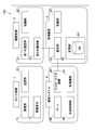
- FIG. 7A to 7D are diagrams showing outputs from the sensor devices 1 mounted on different livestock A1, A2, A3, and A4, and the bar graph schematically shows the pattern of the number of times of reception of the identifier of each module. It is shown in.
- “light” described in the graph indicates the number of receptions of the identifier of the module having the solar power generation unit 11a
- “heat” indicates the number of receptions of the identifier of the module 10b having the temperature difference power generation unit 11b.
- “Vibration” indicates the number of receptions of the identifier of the module 10c having the vibration power generation unit 11c
- “Radio wave” indicates the number of receptions of the identifier of the module 10d having the radio wave generation unit 11d.
- the greater the number of identifiers received from each module within a predetermined time the greater the amount of power generation. For this reason, in the following description, when the number of receptions of the identifier from the module is large, it is expressed as “the power generation amount of the power generation unit mounted on the module is large”, and when the number of receptions is small, the “power generation amount is It is expressed as “less”.
- the CPU 31 of the management device 3 can estimate the place where livestock stays based on the power generation information of the solar power generation unit 11a. 7A and 7B is compared with the power generation amount of the solar power generation unit 11a in FIGS. 7C and 7D, and the latter has a larger power generation amount of the solar power generation unit 11a. Thereby, it is estimated that domestic animals A3 and A4 are longer in the pasture farm than domestic animals A1 and A2.
- a more detailed place of stay for livestock can be estimated based on the amount of power generated from the radio wave generator 11d. For example, by comparing the power generation amount from the radio wave generator 11d of FIGS. 7C and 7D, it is estimated that the livestock A3 is staying in a place with more radio waves than the livestock A4. Therefore, when a distribution of places where the radio wave intensity is strong and weak is formed in the grazing field, it is possible to estimate the place where the livestock stays in the grazing field from the amount of power generated from the radio wave generator 11d.
- the CPU 31 of the management device 3 can estimate the activity amount of livestock based on the power generation information of the vibration power generation unit 11c. 7A and 7B, and FIGS. 7C and 7D compare the power generation amount of the vibration power generation unit 11c, and the latter has a larger power generation amount of the vibration power generation unit 11c.
- livestock A3 and A4 have more activity than livestock A1 and A2.
- the length of the staying time outdoors can be estimated from the power generation amount from the solar power generation unit 11a.
- livestock staying outdoors for a long time is considered to be active, so the amount of livestock activity can also be estimated indirectly from the amount of power generated by the solar power generation unit 11a.
- the state of the livestock can be estimated from the variation in the power generation amount. For example, when the power generation amount of the vibration power generation unit 11c is large on average, it can be estimated that the individual has a large amount of activity as a whole. On the other hand, when the variation in the power generation amount of the vibration power generation unit 11c is large, it is estimated that there is a possibility of receiving an impact or having some trouble.
- the CPU 31 can estimate the behavior of the livestock by analyzing the power generation frequency pattern based on the power generation information of the vibration power generation unit 11c. For example, since the vibration frequency differs between the movement of the ear with the sensor device 1 and the movement of the limbs, the power generation pattern is also different, and these actions can be identified. In addition, if a characteristic power generation pattern is seen in walking movement, running movement, mounting, etc. of livestock, these behaviors can be estimated.
- the CPU 31 of the management device 3 can estimate the presence or absence of heat generated from livestock based on the power generation information of the temperature difference power generation unit 11b and the solar power generation unit 11a.
- the power generation amount of the temperature difference power generation unit 11b in FIG. 7A and FIG. 7B is compared, and the former has a larger power generation amount of the temperature difference power generation unit 11b.
- the electric power generation amount of these solar power generation parts 11a it is comparable. Accordingly, it is estimated that the livestock A1 has a higher body temperature than the livestock A2 even though the livestock A1 and A2 were both indoors for the same amount of time.
- the power generation amount in FIG. 7C is larger. Accordingly, it is estimated that the amount of power generated by the temperature difference power generation unit 11b is increased because the livestock A3 has stayed at a place where the temperature is lower than that of the livestock A2 (for example, outdoors such as pasture). Therefore, although the livestock A3 has much power generation amount of the temperature difference power generation part 11b, it is estimated that the possibility of heat_generation
- the causes of fever in livestock include, for example, illness, stress, and estrus. Therefore, by estimating the presence or absence of heat generation, the above-mentioned factors that cause heat generation can also be estimated.
- the CPU 31 of the management device 3 can estimate, for example, whether or not it is an estrus period based on the power generation information. Thereby, the reproduction management very important in the management of livestock can be facilitated. In the estrus period, the amount of activity generally increases and the body temperature increases. Thereby, CPU31 can estimate whether it is an estrus period based on the power generation information from vibration power generation part 11c, temperature difference power generation part 11b, etc. as mentioned above.
- the CPU 31 of the management device 3 can estimate the meat quality based on the power generation information. Thereby, the meat quality which can be confirmed only after processing as meat can be estimated in the state of the living body. Moreover, in view of the estimated meat quality, management that improves the meat quality can be performed, and the economic value of livestock can be improved.
- the meat quality of livestock is generally considered to be affected by feed, exercise load, stress, and the like. As described above, exercise load (activity amount) and stress can be estimated from the power generation information. Moreover, if the feed can grasp
- the management apparatus 3 can estimate the state of various livestock based on the power generation information, and can facilitate livestock management such as grazing. Hereinafter, specific estimation processing of the management apparatus 3 will be described.
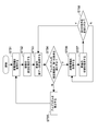
- FIG. 8 is a flowchart illustrating a basic operation example of the management apparatus 3.
- the operation subject is the CPU 31 of the management apparatus 3.
- the CPU 31 estimates the state of a certain livestock using an algorithm generated by machine learning and generates a control signal for an external device using the estimation result.
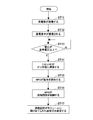
- the CPU 31 acquires power generation information transmitted from the sensor device 1 attached to livestock (ST21). More specifically, the CPU 31 can acquire the identifier received by the communication unit 33 via the communication device 2 as power generation information.
- the CPU 31 estimates the state of the livestock A from the acquired power generation information based on an algorithm for estimating the state of the livestock (ST22).
- An algorithm for estimating the state of livestock will be described.
- the algorithm of the present embodiment is generated by machine learning and is configured to be able to estimate the state of livestock based on power generation information.
- the algorithm may be generated by the CPU 31 of the management apparatus 3 or may be generated by another information processing apparatus.
- the algorithm is stored in the storage unit 32.
- the livestock management database 321 of the management device 3 stores teaching data used for generating the algorithm.
- the teaching data is a data set including sample power generation information acquired from the sensor device 1 attached to a livestock sample and sample actual data indicating an actual state of the sample livestock.
- the livestock sample here refers to livestock that provided data that is the basis for algorithm generation.
- the actual data is data indicating the actual state of the livestock corresponding to the acquired identifier
- the sample actual data is data regarding the actual state of the sample livestock.
- the actual data can be data on the grade of meat obtained when the livestock is processed as meat.
- CPU31 produces
- the external device here can be the livestock production system 4 shown in FIG. 2, for example.
- the CPU 31 can generate a control signal including the information.
- the master monitor apparatus 41 can control the gate 42 based on the said control signal so that the open time of the gate 42 of the barn of the barn to which the livestock belongs may be lengthened.
- the control signal containing the said information can be produced
- the master monitor apparatus 41 can control the automatic feeder 43 so that the feed which supplements the nutritional balance of livestock may be mixed and fed from the estimated vegetation at the place of stay. Further, the CPU 31 generates a control signal for displaying, for example, the identification information of the individual of the livestock identified by the identifier sent from the sensor device and the estimated state on the display unit (display) of the master monitor device 41. You can also.
- the CPU 31 controls the communication unit 33 to transmit the generated control signal (ST24). For example, by transmitting the identified livestock identifier and the estimated information of the livestock to the master monitor device 41, the livestock identifier and the estimated state of the livestock are displayed on the display of the display unit of the master monitor device 41. .
- the management device 3 can acquire information on the behavior of the livestock and the environment around the livestock from the sensor device 1, and can estimate the state of activity, health, etc. of each livestock. Thereby, the power consumption for monitoring can be suppressed. Therefore, it is possible to save maintenance work such as disposal of the sensor device 1, battery replacement, and charging. Moreover, since the sensor device 1 can be downsized, the risk of breakage due to a collision between livestock can be reduced. Furthermore, the possibility of accidents due to accidental swallowing / eating of batteries can be reduced. Furthermore, since the CPU 31 of the management device 3 can generate a control signal based on the estimated information, the control according to the state of the livestock is also executed for the livestock system 4 and the like introduced in the livestock facility. Can be made.
- the management device 3 can automatically receive power generation information from the plurality of sensor devices 1 and can easily acquire the power generation information from the plurality of sensor devices 1 in a lump. Thereby, the labor which collects data manually for every sensor apparatus 1 can be saved. Furthermore, since the CPU 31 of the management device 3 can estimate the state of the livestock based on an algorithm generated by machine learning, it can accurately estimate the state of the livestock. Hereinafter, an operation example that can further improve the estimation accuracy of the algorithm will be described.
- FIG. 9 is a flowchart showing an operation example related to algorithm evaluation in the management apparatus 3.
- the operation subject is the CPU 31 of the management apparatus 3.
- the CPU 31 estimates the state of a certain livestock using an algorithm generated by machine learning, and evaluates and corrects the algorithm based on the actual data of the livestock.
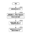
- the CPU 31 acquires the power generation information transmitted from the sensor device 1 (first sensor device) attached to the livestock A1 (ST31).
- the CPU 31 estimates the state of the livestock A1 based on the acquired power generation information and the algorithm (ST32). As described with reference to FIG. 8, the algorithm can be generated by machine learning using teaching data.
- the CPU 31 acquires actual data indicating the actual state of the livestock A1, and stores it in the storage unit 32 (ST33).
- the actual data acquisition method by the CPU 31 is not particularly limited.
- the CPU 31 may control the communication unit 33 so as to acquire the actual data from the information terminal or the like in which the actual data is stored via the network N, or the CPU 31 may manage the management device.
- Actual data may be acquired via an external memory or the like connected to 3.
- the CPU 31 determines whether or not the estimation accuracy of the algorithm satisfies the first condition based on the evaluation result of the state of the livestock A1 estimated with respect to the actual data of the livestock A1 (ST34).
- the first condition can be a condition that the correct answer rate of the state of the livestock estimated using the generated algorithm is a correct answer rate equal to or higher than a predetermined value.
- the correct answer rate is the ratio of the number of correct answers in the estimated state to the total number of livestock from which actual data and sample actual data are acquired.
- the CPU 31 can determine “correct answer” when it is determined that the estimated state of the livestock is equivalent to the actual state of the livestock in the actual data.
- the correct answer rate of a predetermined value or more is not particularly limited, but may be a correct answer rate of 95% or more, for example.
- the CPU 31 determines whether or not the actual data of the livestock A1 and the estimated state of the livestock A1 are equivalent (correct answer), and the determination result is stored as a plurality of teaching data. Reflect the correct answer rate for livestock samples.
- the CPU 31 When it is determined that the evaluation result satisfies the first condition (Y in ST34), the CPU 31 returns to ST31 and repeats the process for the livestock A2 different from the livestock A1.
- the CPU 31 executes an algorithm based on the evaluation result of the actual data of the livestock A1 and the estimated state of the livestock A1. Correct (ST35). And CPU31 returns to ST31 and repeats a process about domestic animal A2 different from domestic animal A1. That is, the CPU 31 acquires power generation information transmitted from the sensor device 1 (second sensor device) attached to the livestock A2 (ST31), and based on the acquired power generation information and the corrected algorithm, The state of A2 is estimated (ST32). Furthermore, the CPU 31 proceeds with the process in the same manner as the domestic animal A1, and corrects the algorithm again as necessary.
- the CPU 31 can construct an algorithm with higher estimation accuracy.
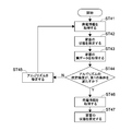
- FIG. 10 is a flowchart illustrating another example of the operation relating to the algorithm evaluation of the management apparatus 3.
- the operation subject is the CPU 31 of the management apparatus 3. Since ST41 to ST45 in FIG. 10 are the same as ST31 to ST35 in FIG. 9, respectively, description thereof is omitted.
- the processing is different in that the evaluation is omitted.
- the CPU 31 acquires the power generation information transmitted from the sensor device 1 (second sensor device) attached to the livestock A2. (ST46) Based on the acquired power generation information and the algorithm, the state of the livestock A2 is estimated (ST47), and the process ends.
- FIG. 11 is a flowchart illustrating another example of the operation related to the evaluation of the algorithm of the management device 3.
- the operation subject is the CPU 31 of the management apparatus 3. Since ST51 to ST57 in FIG. 11 are the same as ST41 to ST47 in FIG. 10, respectively, description thereof is omitted.
- the CPU 31 evaluates the estimation accuracy of the algorithm again when the predetermined condition is satisfied without terminating the process in ST57.
- the CPU 31 determines whether or not the second condition related to the algorithm modification time is satisfied (ST58).
- the second condition can be, for example, a condition such as a period that has elapsed since the previous algorithm modification or the number of livestock whose state has been estimated after the previous algorithm modification.
- the CPU 31 returns to ST53, acquires actual data (second actual data) indicating the actual state of the livestock A2, and stores it in the storage unit 32.
- the CPU 31 determines whether the estimation accuracy of the algorithm satisfies the first condition based on the evaluation result of the state of the livestock A2 estimated with respect to the actual data of the livestock A2 (ST54), and repeats the process. On the other hand, when it is determined that the second condition is not satisfied (N in ST58), CPU 31 returns to ST56 and acquires power generation information for livestock A3 different from livestock A2.
- the estimation accuracy of the algorithm can be reevaluated at a predetermined timing.
- algorithm maintenance can be automatically performed during a long monitoring period.
- Information regarding the state of the livestock estimated by the management device 3 can be used as follows.
- API generation An example in which the CPU 31 generates a control signal for controlling an external device from the estimated state of the livestock has been described.
- the estimated state of the livestock can be used as follows. That is, the CPU 31 may process livestock state data estimated using an algorithm and generate an API (Application Programming Interface) that is used by software installed in an external device or the like.
- API Application Programming Interface
- the software may be part of a loan amount determination application program that determines a loan amount to a livestock farmer or provide data to the program.
- the state of livestock can be the meat quality involved in the loan amount, the health condition of livestock, or the like.
- the loan amount determination application program can be installed in an information processing apparatus of a financial institution that provides funds to a livestock producer, for example.
- the loan amount determination application program can generate a sales amount prediction algorithm by machine learning using information on the estimated state of the livestock and actual data such as the actual sales amount of the livestock industry.
- the loan amount determination application program can determine the loan amount by predicting the sales amount of the livestock industry from the estimated livestock state of the livestock industry who wants to determine the loan amount by using the sales amount prediction algorithm. .
- the financial institution can grasp the management state of the livestock farmers based on the estimation result by the management device 3, and can determine an appropriate loan amount.
- an appropriate loan amount for example, not only information such as the number of livestock owned by livestock farmers, but also information such as the management status of livestock farmers and the economic value of livestock can be grasped more accurately, thereby reducing financing risk. it can.
- livestock farmers raised by the livestock farmers are legitimately evaluated by a system managed by a third party. It is possible to increase the added value of livestock by making it a value. For this reason, livestock farmers can increase profits, and financial institutions can further reduce the risk of financing.
- the CPU 31 of the management device 3 acquires an API request from an external device that has predetermined software installed.
- the API request includes, for example, identification information (ID) of the livestock industry and request data corresponding to request function return data including, for example, livestock management information of the livestock industry.
- ID identification information
- request data corresponding to request function return data including, for example, livestock management information of the livestock industry.
- the CPU 31 generates information requested by the API based on the livestock activity history information for each livestock associated with the livestock farmer ID.
- Livestock activity history information for each livestock refers to information associated with livestock identifiers.
- the CPU 31 transmits information generated based on the API request to the external device.
- livestock activity history information includes accumulated activity, accumulated sunshine, accumulated heat, accumulated radio exposure, activity deviation, sunshine deviation, calorie deviation, radio exposure deviation, accumulated travel, average travel, travel Contains one or more information such as quantity deviation value, meat quality level (final), meat quality level (average), meat quality level (initial), meat quality level (highest / lowest).
- the API request may be livestock activity history information for each livestock.
- the CPU 31 generates information requested by the API based on the livestock activity history information generated from the power generation information associated with the livestock identifier.
- the livestock activity history information includes, for example, one or a plurality of information exemplified above.
- the CPU 31 may be configured to estimate the state of each of the plurality of livestock based on the power generation information, and to specify the livestock having a predetermined state among the plurality of livestock. For example, the CPU 31 can estimate whether or not each of the plurality of livestocks is in the estrus period based on the power generation information, and can identify the livestock estimated to be in the estrus period. In this case, the CPU 31 can specify the livestock by using the acquired module identifier of the sensor device.
- the CPU 31 can generate a control signal including information on the identified livestock and identification information on the livestock. With this control signal, it is possible to notify a user such as a livestock farmer of livestock having a predetermined state.
- the external device to which the control signal is transmitted can be a notification device that notifies the specified livestock information.
- FIG. 12 is a block diagram illustrating a configuration of this application example.
- the notification device 5 may be, for example, an information processing device such as a smartphone, a tablet terminal, or a PC that can be connected to the management device 3 via the network N or the like. These information processing apparatuses can notify livestock farmers (users) of information on livestock specified by display on a display device, sound by a speaker, or the like.
- the notification device 5 may be the master monitor device 41 of the livestock system 4.
- the specific notification method is not limited, for example, you may notify livestock ID with a display device or a speaker.
- the position may be notified. Thereby, the user can search for the livestock identified through the information terminal.
- the timing of notification by the notification device 5 is not particularly limited.
- the notification device 5 may be configured to automatically start notification after receiving a control signal from the management device 3, or configured to start notification by a user's predetermined input operation. Also good. As an example of the latter case, for example, when the user brings the portable information processing terminal as the notification device 5 close to the communication device and executes a predetermined input operation, the portable information processing terminal receives the control signal and notifies Can start.
- the notification device 5 is not limited to a configuration that directly communicates with the management device 3, and may be communicable with the management device 3 via a communication device.
- the “communication device” may be the communication device 2 described above or another communication device.
- the notification device 5 is not limited to the information processing device.
- the notification device 5 may be configured to be attachable to each domestic animal.
- the notification device 5 may be attached to the sensor device 1 or may be realized by the sensor device 1 itself.
- the notification device 5 may be attached to an individual identification tag attached to livestock.
- the notification device 5 includes a display unit such as an LED (Light Emitting Diode). Thereby, the user can specify the livestock of the estrus period, for example by searching the livestock whose display part of the notification apparatus 5 is lit.
- the notification device 5 may be a moving body that moves in the vicinity of each domestic animal.
- the control signal may include information on the position of the livestock in addition to information on livestock having a predetermined state.
- the moving body may be a flying body or a traveling body that travels on the ground.
- these mobile bodies may be configured to be capable of independent flight or traveling independently.
- the moving body can guide the user to a target livestock having a predetermined state. Or the moving body which moved to the vicinity of livestock becomes a mark of the position of livestock, and can also guide a user.
- the above-described external devices are not limited to the master monitor device 41 and the notification device 5 of the livestock system 4, and may be individual devices constituting the livestock system 4, for example.
- the external device may be an information terminal such as a smartphone, a tablet terminal, or a PC that can be connected to the management apparatus 3 via the network N. Thereby, it is possible to present the livestock state estimation result to the user who uses the information terminal.
- the CPU 31 may estimate a plurality of states in order to grasp the environment and health status of the livestock in a multifaceted manner. For example, as the plurality of states, the staying place of each livestock, the amount of activity, the abnormal frequency of body temperature, the meat quality, whether or not it is in estrus, and the like can be mentioned. For example, the CPU 31 can estimate each of the plurality of states by separate processing. Alternatively, when estimating a plurality of states having correlations, the CPU 31 estimates the first state from the power generation information, as shown below, and then differs from the first state to the second state. The state can also be estimated.
- the plurality of states having a correlation can include, for example, activity amount and meat quality, stress and meat quality, stress and milk yield, etc. The “state” is described as “meat quality”.
- FIG. 13 is a flowchart showing another example of the operation related to the evaluation of the algorithm of the management device 3.
- the operation subject is the CPU 31 of the management apparatus 3.
- ST61 to ST67 in FIG. 13 are the same as ST41 to ST47 in FIG. 10, respectively. That is, the CPU 31 acquires the power generation information transmitted from the sensor device 1 (first sensor device) attached to the livestock A1 (ST61), and then estimates the acquired power generation information and the amount of activity. Based on the algorithm (first algorithm), the amount of activity (first state) of livestock A1 is estimated (ST62). Subsequently, the CPU 31 acquires actual data (first actual data) indicating the actual activity amount of the livestock A1, and stores it in the storage unit 32 (ST63).
- the CPU 31 determines whether the estimation accuracy of the first algorithm satisfies the first condition based on the evaluation result of the activity amount of the livestock A1 estimated with respect to the actual data of the livestock A1 (ST64). On the other hand, when it is determined that the evaluation result does not satisfy the first condition (N in ST64), the CPU 31 determines the first based on the evaluation result of the actual data of the livestock A1 and the estimated amount of activity of the livestock A1. 1 algorithm is modified (ST65). And CPU31 returns to ST61 and repeats a process about the domestic animal A2 different from the domestic animal A1.
- CPU 31 acquires the power generation information transmitted from sensor device 1 (second sensor device) attached to livestock A2 (ST66). ) Based on the acquired power generation information and the first algorithm, the activity amount (first state) of the livestock A2 is estimated (ST67).
- the CPU 31 estimates the meat quality of the livestock based on the algorithm (second algorithm) for estimating the meat quality (second state) of the livestock from the estimated amount of activity (first state) ( ST68). Subsequently, the CPU 31 acquires actual data (second actual data) indicating the actual meat quality of the livestock A2, and stores it in the storage unit 32 (ST69).
- the CPU 31 determines whether or not the estimation accuracy of the second algorithm satisfies the third condition based on the meat quality evaluation result of the livestock A2 estimated with respect to the actual data of the livestock A2 (ST70).
- the third condition may be a condition that the correct answer rate of the meat quality of the livestock estimated using the generated second algorithm is a correct answer rate equal to or higher than a predetermined value.
- the CPU 31 When it is determined that the evaluation result satisfies the third condition (Y in ST70), the CPU 31 returns to ST66 and repeats the process for the livestock A3 different from the livestock A2.
- the CPU 31 determines the second based on the evaluation result of the actual data of the livestock A2 and the estimated meat quality of the livestock A2. The algorithm is corrected (ST71). Then, the CPU 31 returns to ST66 and repeats the process using the second algorithm corrected for the livestock A3 different from the livestock A2.
- the CPU 31 can estimate the state of each domestic animal within a predetermined period by processing the estimated state of each domestic animal over time. For example, the CPU 31 can calculate the grazing time by accumulating the time during which a certain livestock stays in the grazing land continuously. Also, the exercise time can be calculated by integrating the time with a relatively large amount of activity. Furthermore, CPU31 may produce
- the sensor device 1 may transmit time information associated with the power generation information together with the power generation information.
- the module of the sensor device 1 can be configured as follows.
- FIG. 14 is a diagram illustrating an example of a specific configuration of the module 10 b of the sensor device 1. Similar to the module 10a described above, the module 10b includes, for example, the power generation unit 11b, the regulator IC 101, the charger 102, the secondary battery 103, the capacitor 104, the capacitor 105, the reset IC 106, the MPU 107, and the storage unit. 108 and a communication circuit 109.
- the storage unit 108 includes a ROM 108a and a RAM 108b.
- the sensor device 1 includes the module 10a, the module 10b, the module 10c, and the module 10d.
- Each module includes the power generation unit 11, the power storage element 12, and the transmission unit 13. Have each.
- the module 10b will be described as an example.
- the configuration of other modules in the sensor device 1 is the same as the configuration of the module 10b, for example, but there may be a difference in configuration for each module.
- the module 10b has an RTC (Real Time Clock) 150.
- the RTC 150 is connected to the MPU 107 and supplies time information to the MPU 107. Time information can be set as appropriate, such as date.
- the MPU 107 may be configured to incorporate an RTC.
- the power supply device for driving RTC150 may be provided in the sensor apparatus 1.
- the power supply device is a secondary battery such as a lithium ion battery or a primary battery. Since the power consumption of the RTC 150 is small, a small battery such as a coin type may be used. Alternatively, the electric power stored in the secondary battery 103 may be supplied to the RTC 150.
- the MPU 107 supplies time information supplied from the RTC 150 together with the identifier of the module 10b to the communication circuit 109 in response to the reset IC 106 transitioning from the off state to the on state.
- the communication circuit 109 transmits the identifier of the module 10b and time information to an external device through communication.
- control unit 23 of the communication device 2 or the CPU 31 of the management device 3 may associate the time information with the received power generation information, specifically, the control unit 23 of the communication device 2. Or CPU31 may have RTC. Also by this, the control part 23 or CPU31 of the communication apparatus 2 can estimate the time-dependent state of each domestic animal.
- the CPU 31 may acquire information related to the position of the sensor device 1 based on the transmission of the sensor device 1.
- the information regarding the position here includes information on at least one of the distance from the reference position of the sensor device 1 and the orientation viewed from the reference position of the sensor device 1.
- the reference position can be the position of the communication device 2, for example.
- the communication device 2 may include a CPU (not shown). Thereby, the communication apparatus 2 can generate information related to the position of the sensor apparatus 1 with respect to the position of the communication apparatus 2, and perform processing for associating the information with the power generation information transmitted from the sensor apparatus 1.
- the method for acquiring information related to the position by the CPU 31 is not particularly limited. For example, it is known that there is a correlation between the signal strength of communication data and the communication distance. Therefore, the communication device 2 can transmit information on the signal strength from the sensor device 1 to the management device 3 together with the power generation information. Specifically, when transmitting the received identifier information, the communication device 2 can transmit information related to signal strength in association with this information. Thereby, CPU31 can acquire the information regarding the distance of the sensor apparatus 1 from the communication apparatus 2.
- the first communication unit 21 of the communication device 2 has an antenna, and the directivity of the sensor device 1 viewed from the communication device 2 is changed by the communication device 2 by changing its directivity mechanically or electrically. Can be acquired and transmitted to the management device 3.
- Sensor device 1 may have a GPS communication part (not shown), and may be able to transmit position information. In this case, the sensor device 1 may be provided with a power supply device for driving the GPS communication unit.
- Modification 1-4 Modification of Sensor Device
- the configuration of the sensor device 1 is not limited to the configuration described above, and various configurations can be adopted.
- the sensor device 1 is not limited to a configuration having all the modules 10a to 10d, and may have a configuration having at least one of these modules.
- the sensor device 1 may include a module including the power generation unit 11 having a configuration other than the above-described power generation units 11a to 11d.
- the sensor device 1 may have a main communication circuit connected to the communication circuits of the modules 10a to 10d.
- the main communication circuit functions as a part of the “transmission unit”.
- a plurality of modules may share a communication circuit.
- the regulator IC 101, the charger 102, the secondary battery 103, the capacitor 104, and the capacitor 105 may be configured not to have all or part of them as necessary.
- the MPU 107 may be configured to have the function of the reset IC 106. In this case, the MPU 107 functions as a part of the “transmission unit”.
- the transmission unit 13 may be configured with a switch whose conduction state is variable by switching contacts, for example, instead of the reset IC 106.
- the switch may include a bimetal that can be deformed by thermal energy.
- the sensor device 1 may include a heat storage element that stores thermal energy and supplies the heat energy to the power generation unit 11 and the bimetal.
- the power generation unit 11 converts thermal energy into electrical energy. The bimetal deforms due to thermal expansion and contacts the contact. Thereby, the electric power generation part 11 and MPU107 can conduct
- the sensor device 1 may have a livestock element that can switch between a kinetic energy accumulation state and an open state.
- An example of the animal power element is a mainspring.
- the power generation unit 11 is connected to the animal power element and has a mechanism for generating power by electromagnetic induction.
- the power generation unit 11 includes, for example, a magnet and a coil, and the magnet is configured to be displaceable with respect to the coil.
- the electric power generation part 11 can drive a magnet according to the kinetic energy supplied from an animal power element, and can generate electric power.
- the sensor device 1 can transmit power generation information when the MPU 107 is operated by the electric energy generated by the power generation unit 11.
- the sensor device 1 having the photovoltaic power generation unit 11a, the temperature difference power generation unit 11b, the vibration power generation unit 11c, and the radio wave power generation unit 11d, but other devices may be mounted as the sensor 1.
- various sensors such as an acceleration sensor, a gyro sensor, a geomagnetic sensor, a temperature sensor that measures the body temperature of a livestock equipped with the sensor device 1 and a temperature around the sensor device 1, and a pulse sensor are mounted on the device 1. Also good. Moreover, it is good also as a structure which these sensors drive based on the electric power generated by the said electric power generation part.
- the transmission unit 13 of the sensor device 1 may transmit information obtained from these sensors to the communication device 2 and the management device 3 together with the power generation information. Further, the management device 3 may receive information transmitted by these sensors of the sensor device 1 by the communication unit 33 and use it when estimating the state of the livestock in ST22 of FIG.
- Modification 1-5 Modification of estimation method
- the CPU 31 may estimate the state of the livestock based on a predetermined algorithm that can analyze the state of the livestock from the power generation information.
- This secondary information is, for example, information for estimating the state of the livestock as described with reference to FIG. 7, for example, a numerical value of the power generation amount of each power generation unit such as a solar power generation unit, It may be a time differential value of the amount of power generation that is digitized. More specifically, the information obtained by digitizing the power generation amount can be calculated based on the reception frequency (that is, the length of the reception interval) of the power generation information received by the CPU 31 from the same sensor device 1.
- the management apparatus 3 may receive the information which digitized the electric power generation amount from the sensor apparatus 1, and CPU31 may produce
- the CPU 31 compares the secondary information with index data serving as an index of a state to be estimated.
- the index data can be a predetermined reference value.
- the index data can be a statistical value such as an average value of power generation, which will be described later.
- the CPU 31 estimates the state of the livestock based on the comparison result. Thereafter, the CPU 31 can generate a control signal for controlling the external device based on the estimated state of the livestock, and transmit this control signal to the external device.
- the CPU 31 calculates a differential value (secondary information) of the power generation amount of the photovoltaic power generation unit 11a with time, and sets the timing at which the differential value is equal to or greater than a predetermined value (index data) between indoor (animal barn) and outdoor ( It can be determined as the timing of movement with the grazing land.
- the CPU 31 can also set the grazing time from the time when the differential value becomes a positive value having a large absolute value to the time when the differential value becomes a negative value having a large absolute value.
- FIG. 15 is a graph for explaining an example of processing using the solar power generation unit 11a (solar power generator) of Modification 1-5, where the horizontal axis represents time and the vertical axis represents the power generation amount of the solar power generation unit 11a. Is shown schematically.
- CPU31 is calculating the time differential value in each time of electric power generation amount. In the example shown in the figure, the amount of power generation increases sharply between time t1 and time t2, and the CPU 31 determines that the differential value between time t1 and t2 is greater than or equal to a positive (0 or more) first differential value.
- the CPU 31 determines that the differential value between time t3 and t4 is equal to or less than a negative (less than 0) second differential value. To do. Further, the CPU 31 determines that the differential value between time t2 and t3 is greater than the second differential value and less than the first differential value. Then, the CPU 31 shifts the time differential value from a value greater than the second differential value to a second differential value or less from time t2 when the time differential value shifts from the first differential value to less than the first differential value. The time t23 until the time t3 can be estimated as the time when the livestock was outdoors, that is, the grazing time.
- the CPU 31 digitizes the power generation amount based on the reception frequency of the power generation information, that is, the length of the reception interval, and the power generation information is frequently received during t23 when the power generation amount is large. I understand. Moreover, CPU31 can also estimate weather etc. by calculating the integrated value (secondary information) of the electric power generation amount of the solar power generation part 11a during grazing. Moreover, when the memory
- the CPU 31 determines the statistical value (relative index data) of the power generation amount from the plurality of sensor devices 1 belonging to the same management range (for example, the same region, ranch, pasture, cowshed, etc.) and one sensor device 1 By comparing the power generation information, the state of the livestock wearing the sensor device 1 can be estimated.
- FIG. 16 is a graph showing an example of processing using the temperature difference power generation unit 11b (temperature difference generator) of Modification 1-5, where the horizontal axis indicates identifiers A1 to A10 of ten different sensor devices 1. The vertical axis represents the relative body temperature value detected by the temperature difference power generation unit 11b.
- the secondary information is a relative body temperature value calculated by the CPU 31 based on the reception interval of the power generation information.
- the average value of the body temperature values A1 to A10 is T1 (for example, the relative body temperature value is 5), and the normal range based on the average value is T2 (for example, the relative body temperature value is 4 to 4). 6).
- the relative index data is a normal range T2.
- the normal range T2 can be defined as a range of an average value +/ ⁇ 20%, for example.
- the CPU 31 compares the normal range T2, which is relative index data, with the power generation information (body temperature data) of each livestock.
- the CPU 31 determines that the livestock in which the body temperature value that does not fall within the normal range T2 is detected as an estrus period in which the body temperature is higher than normal, or hypothermia in which the body temperature is lower than normal, or the like Is estimated.
- the body temperature value of A5 is 8, which is higher than the normal range T2.
- CPU31 can estimate that the livestock corresponding to A5 is in an estrus period, for example.
- the body temperature value of A8 is 2, which is lower than the normal range. For this reason, CPU31 can estimate that the domestic animal corresponding to A8 has hypothermia, for example.
- the CPU 31 has a value (secondary information) corresponding to the power generation amount of the temperature difference power generation unit 11b that is equal to or greater than a predetermined value (index data) from the average value, and the vibration power generation unit 11c
- the value (secondary information) corresponding to the power generation amount is equal to or greater than the average value (index data), and the value (secondary information) corresponding to the power generation amount of the photovoltaic power generation unit 11a is within a predetermined range including the average value. If it is determined that the value (index data), the livestock can be estimated to be in estrus. For example, if the outside air temperature changes even if the body temperature of the livestock is constant, the amount of power generated by temperature difference power generation changes.
- a plurality of sensor devices 1 within the same management range.
- These algorithms and algorithms generated by machine learning may be combined.
- the estrus when the estrus is estimated from the amount of activity by comparing the amount of power generated by vibration power generation with a predetermined threshold value, it may not be possible to detect the state with high accuracy if one threshold is used. For example, if the threshold is set based on the average activity in the barn, if the activity of the entire group of livestock increases due to grazing, it will be determined that the animal that has not actually estrus has been estrus, and it is erroneous. Judgment may be made. Conversely, even if a threshold is set based on the average amount of activity during grazing, estrus cannot be determined with high accuracy. Therefore, by estimating the scene (situation) where the livestock is placed, an appropriate algorithm can be used based on the estimated scene.
- FIG. 17 is a flowchart showing the flow of processing for setting an algorithm based on the estimated scene of Modification 1-5.
- the process shown in FIG. 8 may be a detailed process of the step “estimate the state of the livestock based on the algorithm for estimating the state of the livestock from the power generation information” shown in ST22 of FIG. Good.
- the CPU 31 estimates the scene (situation) where the target livestock is placed based on the environmental information (ST221).
- the estimation of the scene may be performed for each livestock wearing each sensor device 1, for example.
- scene estimation may be performed automatically or manually in groups (groups) set.
- Various information can be used as the environment information used for scene estimation.
- the power generation information of the sensor device 1 can be used as the environmental information. Specifically, it is possible to estimate the staying location from the power generation information by the method described with reference to FIG. 7 and to estimate whether the place is grazing or in a barn.
- grazing time can be estimated based on the differential value of the electric power generation amount of the solar power generation part 11a, and it can be estimated whether it is grazing.
- the CPU 31 determines that all the animals belonging to the herd It may be estimated that livestock are in the same scene.
- position information can be used as environment information.
- the processing can be performed as follows. That is, the communication device 2 transmits the power generation information transmitted from the sensor device 1 and identification information for identifying the communication device 2 to the server device 3.
- the storage unit 32 of the server device 3 stores in advance position information of the communication device 2 corresponding to each identification information and scene information corresponding to each communication device 2.
- the CPU 31 collates the transmitted power generation information and the identification information of the communication device 2 with the stored information, and determines the scene information corresponding to the communication device 2 that has received the power generation information from the sensor device 1 as the sensor device. It is estimated that this is a scene where 1 is placed.
- the storage unit 32 stores information “latitude and longitude (aa, bb) of communication device X, location: milking parlor”
- the CPU 31 stores the livestock corresponding to the sensor device 1 that communicated with the communication device X.
- the placed scene can be estimated as “milking”.
- the position information can be acquired by using the method described in Modification 1-3.
- the environment information information regarding the external environment determined using the secondary information described in the present modification can be used.
- the CPU 31 can also determine that the scene where the livestock is placed is “severe heat” based on the information. Further, the CPU 31 may estimate the scene based on the plurality of environment information described above or environment information obtained by combining other information. The scene estimation may be performed every time the power generation information is received, or the environment information may be generated and processed at an arbitrary time interval.
- the CPU 31 sets a state estimation algorithm for estimating the state of the livestock corresponding to the estimated scene (ST222). For example, when the estimated scene is “grazing”, the CPU 31 can set a state estimation algorithm corresponding to the grazing. Alternatively, when the estimated scene is “in the barn”, the CPU 31 can set a state estimation algorithm corresponding to the inside of the barn.
- Each of these state estimation algorithms may be generated by machine learning, or may be generated from statistical data.
- the plurality of algorithms to be set may be obtained by changing some elements such as a threshold.
- the state estimation algorithm to be set may include an algorithm with the content of “stop further state estimation”.
- the estimated scene for example, “during milking” can be set to the state of livestock.
- CPU31 estimates the state of livestock based on the set state estimation algorithm (ST223). Thereby, it is possible to estimate an appropriate state in different scenes, and to improve the accuracy of state estimation.
- the management device 3 may be an information processing device that can be connected to the network N, for example.
- the management device 3 may be a PC, a smartphone, a tablet terminal, or the like used by a livestock farmer (user).
- the management apparatus 3 may be implement
- the communication unit 33 of the management device 3 (master monitor device 41) is connected to each component of the livestock system 4 by wire or wireless. Even with such a configuration, the livestock management system 100 can be realized.
- the communication device 2 may be realized by at least one of the plurality of sensor devices 1 (hereinafter referred to as a master sensor device 2).
- the master sensor device 2 may be a specific sensor device of the plurality of sensor devices 1 or may be variable depending on the organization of the group.
- FIG. 19 is a schematic diagram showing the concept of this modification.
- the livestock management system 100 includes ten sensor devices 1a to 1j and a management device 3.
- the sensor devices 1a to 1e constitute a first group GP1
- the sensor devices 1f to 1j constitute a second group GP2.
- the groups GP1 and GP2 by the sensor device 1 are configured by sequentially connecting, for example, point-to-point with other sensor devices 1 in which each sensor device 1 exists in a communicable range.
- the sensor devices 1a to 1e belonging to the group GP1 constitute a mesh network, and each of the sensor devices 1a to 1e corresponds to a node and is connected point-to-point, and each power generation information or the like is transmitted.
- the sensor devices 1f to 1j belonging to the group GP2 constitute a mesh network, and the sensor devices 1f to 1j correspond to nodes, and are connected point-to-point to generate power generation information, etc. Can be shared.
- the structure of the said group may change because the sensor apparatus 1 and the livestock to which this is attached move.
- the sensor device 1d and the sensor device 1g function as the master sensor device 2 and are configured to be communicable with the management device 3.
- These master sensor devices 2 can transmit the power generation information of each sensor device 1 belonging to each group GP1, GP2 to the management device 3.
- the transmission unit 13 of the master sensor device 2 includes a communication circuit that can be connected to the management device 3 in addition to a communication circuit that can communicate between the sensor devices 1.
- the configuration of the communication circuit is appropriately determined according to the communication method with the management apparatus 3. For example, when the management apparatus 3 is connected to the network N, the communication circuit uses a wireless LAN (IEEE802.11 or the like) such as WiFi (Wireless Fidelity) or a 3G or 4G network for mobile communication. N is connectable.
- a wireless LAN IEEE802.11 or the like
- WiFi Wireless Fidelity
- 3G or 4G network for mobile communication.
- each sensor device 1 belonging to each group GP1, GP2 can acquire information on the intensity of signals transmitted from other connected sensor devices 1.
- the sensor device 1d and the sensor device 1g can transmit the signal intensity information between the sensor devices 1 in association with the power generation information. Therefore, the CPU 31 can acquire information related to the distance between the sensor devices 1 as in Modification 1-3.
- CPU31 can acquire the information regarding the distance between each sensor apparatus 1, and can estimate the position of each sensor apparatus 1 accurately.
- the management device 3 can adjust the power generation information acquired from the sensor device 1.
- the “adjustment” here may be, for example, calibration.
- the management device 3 may calibrate the output of one sensor device 1 based on, for example, statistical values of power generation information from a plurality of sensor devices 1, or may change over time from one sensor device 1. You may adjust the output of the sensor apparatus 1 by processing power generation information statistically.
- Calibration may be performed based on the difference in the amount of power generated in the system. That is, for example, livestock is exposed to the same light source area, the same vibration area, the same radio wave intensity area, and the same temperature area. Calibration may be performed by making the output of each power generation unit uniform at this time. In addition, by setting a normal / abnormal threshold for the output of the power generation unit at this time in advance, an abnormality of the sensor device or an abnormality of the power generation unit may be detected and used for maintenance information.
- the area of the same environment may be installed on a passage through which livestock passes, or may be a space other than a passage.
- the temperature / humidity / illuminance controller of the space where livestock usually spend may be controlled to create a uniform environment space, or a dedicated space for creating a more stable environment space.
- the output adjustment (calibration) of the sensor device 1 by the management device 3 may be performed simultaneously with the estimation process of the state of the livestock, or may be performed separately from the estimation process. When the output adjustment is performed separately from the estimation process, the management device 3 can perform the output adjustment at a timing according to an input operation by the user, for example.
- the livestock management system 100 may not have the plurality of sensor devices 1 and may have only one sensor device. Thereby, CPU31 can presume the state of the livestock with which the said sensor apparatus 1 was mounted
- the management apparatus 3 is not limited to the example comprised by one information processing apparatus, You may be comprised by the several information processing apparatus.
- FIG. 20 is a block diagram illustrating a configuration of a livestock management system 100A according to the second embodiment of the present technology.
- the same reference numerals are given to the same configurations as those in the above-described embodiment, and the description is omitted.
- the livestock management system 100A includes the sensor device 1 and the management device 3, but does not include the communication device 2. That is, the transmission unit 13 of the sensor device 1 has at least a communication circuit for performing direct communication with the management device 3.
- the configuration of the communication circuit is appropriately determined according to the communication method with the management device 3.
- the communication circuit includes a wireless LAN (IEEE802.11 or the like) such as WiFi (Wireless Fidelity) or a 3G or 4G network for mobile communication. And can be connected to the network N.
- the communication circuit includes “Wi-Fi (registered trademark)”, “Zigbee (registered trademark)”, “Bluetooth”. Connected to the management device 3 using near field communication such as (registered trademark), Bluetooth Low Energy, ANT (registered trademark), ANT + (registered trademark), and EnOcean (registered trademark) can do.
- management device 3 may be realized by the master monitor device 41 of the livestock system 4 as described in the modification example 1-6.
- the livestock management system 100A can be realized.
- FIG. 21 is a block diagram illustrating a configuration of a sensor device 1B according to the third embodiment of the present technology.
- the sensor device 1B of the present embodiment is configured to be able to estimate the state of livestock. That is, as shown in FIG. 21, the sensor device 1 ⁇ / b> B includes a power generation unit 11, a storage element 12, and a housing 14, and further includes a CPU (control unit) 15, a storage unit 16, and a transmission unit 17.
- the sensor device 1B may have a plurality of modules in the same manner as the sensor device 1. Each module basically has the configuration described in FIG. 5 and the like, but the communication circuit 109 may not be provided.
- the state estimation method the method described in the first embodiment can be applied.
- the housing 14 is configured to be attachable to livestock as shown in FIG. Further, the housing 14 may have an airtight structure.
- the power generation unit 11 is accommodated in the housing 14 and generates electric power according to the surrounding environment.
- the CPU 15 is configured to be able to estimate the state of the livestock based on the power generation information.
- the CPU 15 may be connected to the MPUs 107 of a plurality of modules included in the sensor device 1B with reference to FIG. Alternatively, each module may not be connected to the reset IC 106 without having the MPU 107. Thereby, CPU15 can acquire the presence or absence of the predetermined amount of electric power generation in each module, and the information of electric power generation frequency.
- the state of livestock by the CPU 15 can be estimated as follows. That is, as with the CPU 31, the CPU 15 is generated by machine learning using the sample power generation information and the sample actual data as teaching data from the acquired power generation information, and can estimate the state of the livestock based on the power generation information.
- the state of the livestock can be estimated.
- the CPU 15 may estimate the state of the livestock based on a predetermined algorithm that analyzes the state of the livestock from the power generation information, as described in Modification 1-5.
- the various states described in the first embodiment can be applied to the estimated state.
- the CPU 15 can generate a control signal capable of controlling the external device based on the estimated state of the livestock.
- the external device can be the master monitor device 41 of the livestock system 4.
- the storage unit 16 includes, for example, a ROM that stores a program to be executed by the CPU 15 and a RAM that is used as a work memory when the CPU 31 executes processing. Furthermore, the storage unit 16 may include a nonvolatile memory such as an HDD (Hard Disk Drive) and a flash memory (SSD; Solid State Drive).
- a nonvolatile memory such as an HDD (Hard Disk Drive) and a flash memory (SSD; Solid State Drive).
- the transmission unit 17 is configured as a communication circuit capable of transmitting the generated control signal.
- the transmission unit 17 is connected to the communication device 2 ⁇ / b> B having the same configuration as that of the communication device 2 described above.
- the transmission unit 17 performs “Wi-Fi (registered trademark)”, “Zigbee (registered trademark)”, “Bluetooth (registered trademark)”, “Bluetooth Low Energy”, “ANT (registered trademark)”, “ It may be configured such that near field communication such as “ANT + (registered trademark)” and “EnOcean (registered trademark)” is possible.
- the communication device 2B is configured to be able to communicate with the transmission unit 17, and is further connected to the master monitor device 41 of the livestock system 4 via the Internet or the like. Accordingly, the master monitor device 41 can be controlled as described above based on the control signal generated by the CPU 15.
- the master monitor apparatus 41 can perform the analysis of the state of the some livestock to which the sensor apparatus 1B is mounted based on the control signal transmitted from each sensor apparatus 1B. For example, the master monitor device 41 can also calculate statistical values for the state of a plurality of livestock and extract abnormal individuals in the livestock group to which the sensor device 1B is attached. Thereby, the processing burden of the sensor apparatus 1B can be reduced and the sensor apparatus 1B can be reduced in size.
- a management device is not necessary, and the configuration of the entire system can be reduced in size.
- the sensor device 1 ⁇ / b> B may have various configurations.
- a configuration without the power storage element 12 may be used, or a configuration with an RTC may be used as shown in FIG.
- the sensor device 1B may include a switch whose conduction state can be changed by switching contacts, or may include a livestock element.
- the sensor device 1B may be configured to be connected to the Internet without using the communication device 2B.
- the transmission unit 17 may be configured to be connectable to the Internet by, for example, wired or wireless.
- the transmission part 17 may be an interface connectable with an external apparatus, for example, may be comprised as connectors, such as a USB terminal.
- the control signal can be transmitted by connecting the sensor device 1 ⁇ / b> B to the master monitor device 41.
- the livestock management system 100 may be configured to include only the management device 3.
- this technique can also take the following structures.
- (1) It has a power generation unit that generates electric power according to the surrounding environment, and a transmission unit that transmits power generation information of the power generation unit using the power obtained by the power generation unit, and can be attached to livestock
- a sensor device A livestock management system comprising: a receiving unit that receives the power generation information from the sensor device; and a management device that includes a control unit that estimates the state of the livestock based on the power generation information.
- the livestock management system according to (1) above, The said receiving part has the said electric power generation part and the said transmission part, respectively, The livestock management system which receives the said electric power generation information from each of several sensor apparatus which can be mounted
- the livestock management system according to (2) above, The control unit generates relative indicator data for the plurality of domestic animals to which each of the plurality of sensor devices is attached, using the plurality of power generation information transmitted by the plurality of sensor devices, and the relative indicator data and the The state of the livestock corresponding to the one power generation information is estimated by comparing one power generation information among the plurality of power generation information.
- a livestock management system further comprising a sensor device that has a power generation unit that generates electric power according to the surrounding environment and a transmission unit that transmits power generation information of the power generation unit and can be attached to livestock.
- the transmission unit is configured to be switchable between a standby state and a transmission state in which the power generation information can be transmitted according to the power supplied from the power generation unit. In the transmission state, the transmission unit is assigned to the power generation unit.
- a livestock management system that transmits the generated identifier as power generation information.
- the livestock management system wherein the control unit estimates a state of the livestock based on a reception frequency of the power generation information including the identifier transmitted by the sensor device.
- the livestock management system is a livestock management system that generates power using energy based on at least one of light, heat, vibration, radio waves including a far electromagnetic field and a near electromagnetic field, and a specific organic substance and inorganic substance.
- the livestock management system is a livestock management system which estimates at least one of the stay place of the said livestock, activity amount, action, the presence or absence of a heat
- the control unit is a livestock management system that estimates whether the livestock is in an estrus period based on the power generation information.
- the livestock management system according to any one of (1) to (9) above, The control unit is a livestock management system that estimates the quality of the livestock based on the power generation information.
- the livestock management system according to any one of (1) to (10) above, The said control part produces
- the livestock management system according to any one of (1) to (11) above, The management device further includes a storage unit that stores sample power generation information acquired from the sensor device mounted on a livestock sample, and sample actual data indicating an actual state of the sample livestock, The control unit is generated by machine learning using the sample power generation information and the sample actual data as teaching data, and based on an algorithm capable of estimating the state of the livestock based on the power generation information, A livestock management system that estimates the condition of the animal. (13) The livestock management system according to (12) above, The control unit The power generation unit has the power generation unit and the transmission unit, and estimates the state of the first livestock based on the power generation information acquired from the first sensor device attached to the first livestock and the algorithm.
- the livestock management system according to (13) above, The control unit After estimating the state of the second livestock, it is determined whether or not the second condition regarding the correction time of the algorithm is satisfied, When it is determined that the second condition is satisfied, the second actual data indicating the actual state of the second livestock is stored in the storage unit, and the estimated second for the second actual data is stored.
- the livestock management system which determines whether the estimation precision of the said algorithm satisfy
- the livestock management system according to any one of (1) to (14) above,
- the control unit A livestock management system that sets a state estimation algorithm corresponding to a situation where the livestock is placed based on environmental information indicating an environment around the livestock, and estimates the state of the livestock using the set state estimation algorithm.
- the livestock management system is A power storage element that stores power generated by the power generation unit; a power generation unit that includes a solar power generator and a vibration power generator; and the transmission unit that transmits power generation information by wireless communication; and the power storage element; A housing configured to be attachable to the body, The livestock management system, wherein the housing does not have a lid for replacing the power storage element, and at least a part of the housing is made of a translucent material.
- the power storage element is a livestock management system including a capacitor.
- a livestock management system further comprising a communication device capable of communicating with each of the transmission unit and the reception unit and transmitting the power generation information transmitted from the transmission unit to the reception unit.
- a housing that can be attached to livestock;
- a power generation unit housed in the housing and generating electric power according to the surrounding environment;
- a sensor device comprising: a control unit that is housed in the housing and estimates a state of livestock based on the power generation information.
- the control unit of the information processing device acquires the power generation information of the power generation unit that generates power according to the surrounding environment, The livestock state estimation method in which the control unit estimates the livestock state based on the power generation information.
Landscapes
- Life Sciences & Earth Sciences (AREA)
- Environmental Sciences (AREA)
- Engineering & Computer Science (AREA)
- Animal Husbandry (AREA)
- Biodiversity & Conservation Biology (AREA)
- Birds (AREA)
- Zoology (AREA)
- Business, Economics & Management (AREA)
- Physics & Mathematics (AREA)
- General Physics & Mathematics (AREA)
- Theoretical Computer Science (AREA)
- Marine Sciences & Fisheries (AREA)
- Tourism & Hospitality (AREA)
- Agronomy & Crop Science (AREA)
- Biophysics (AREA)
- Mining & Mineral Resources (AREA)
- General Business, Economics & Management (AREA)
- Health & Medical Sciences (AREA)
- Economics (AREA)
- General Health & Medical Sciences (AREA)
- Human Resources & Organizations (AREA)
- Marketing (AREA)
- Primary Health Care (AREA)
- Strategic Management (AREA)
- Radar, Positioning & Navigation (AREA)
- Computer Networks & Wireless Communication (AREA)
- General Engineering & Computer Science (AREA)
- Catching Or Destruction (AREA)
- Management, Administration, Business Operations System, And Electronic Commerce (AREA)
- Arrangements For Transmission Of Measured Signals (AREA)
Abstract
Priority Applications (2)
| Application Number | Priority Date | Filing Date | Title |
|---|---|---|---|
| JP2017517594A JPWO2016181604A1 (ja) | 2015-05-12 | 2016-04-06 | 家畜管理システム、センサ装置及び家畜の状態の推定方法 |
| US15/571,329 US10314293B2 (en) | 2015-05-12 | 2016-04-06 | Livestock management system, sensor apparatus, and estimation method for a state of a livestock animal |
Applications Claiming Priority (2)
| Application Number | Priority Date | Filing Date | Title |
|---|---|---|---|
| JP2015097687 | 2015-05-12 | ||
| JP2015-097687 | 2015-05-12 |
Publications (1)
| Publication Number | Publication Date |
|---|---|
| WO2016181604A1 true WO2016181604A1 (fr) | 2016-11-17 |
Family
ID=57248917
Family Applications (1)
| Application Number | Title | Priority Date | Filing Date |
|---|---|---|---|
| PCT/JP2016/001922 Ceased WO2016181604A1 (fr) | 2015-05-12 | 2016-04-06 | Système de gestion de bétail, dispositif capteur, et procédé d'estimation d'état de bétail |
Country Status (3)
| Country | Link |
|---|---|
| US (1) | US10314293B2 (fr) |
| JP (1) | JPWO2016181604A1 (fr) |
| WO (1) | WO2016181604A1 (fr) |
Cited By (19)
| Publication number | Priority date | Publication date | Assignee | Title |
|---|---|---|---|---|
| WO2019125114A1 (fr) * | 2017-12-20 | 2019-06-27 | Sanchez Arocha Octavio | Procédé et système sans fil de surveillance de la santé pour bétail d'embouche au moyen de la surveillance du ruminement en temps réel |
| JP2019122368A (ja) * | 2018-01-12 | 2019-07-25 | デザミス株式会社 | 牛の健康状態管理システム及び管理方法並びに健康状態管理プログラム |
| CN110402840A (zh) * | 2019-07-25 | 2019-11-05 | 深圳市阿龙电子有限公司 | 一种基于图像识别的生猪监测终端及生猪监测系统 |
| WO2019235776A1 (fr) * | 2018-06-07 | 2019-12-12 | 엘지이노텍 주식회사 | Dispositif et procédé de détermination d'objet anormal |
| CN110766110A (zh) * | 2019-10-18 | 2020-02-07 | 安徽农业大学 | 一种基于二维码的农药信息快速采集自动分配系统 |
| JP2020027454A (ja) * | 2018-08-11 | 2020-02-20 | アルセンス株式会社 | センサデバイス及び家畜管理システム |
| JP2020036627A (ja) * | 2019-12-17 | 2020-03-12 | Nttテクノクロス株式会社 | 行動特定装置、行動特定方法、及びプログラム |
| KR102106265B1 (ko) * | 2018-12-12 | 2020-05-04 | 경상대학교산학협력단 | 에너지 하베스팅 센서를 이용한 가축의 발정 감지 장치 및 방법 |
| WO2020111070A1 (fr) * | 2018-11-29 | 2020-06-04 | Base株式会社 | Système, procédé et programme informatiques de remise de fonds à un détaillant durant une transaction commerciale électronique |
| KR20200073456A (ko) * | 2018-12-14 | 2020-06-24 | 전자부품연구원 | 케이지 내에서의 활동 에너지 모니터링에 의한 가금류 이상징후 분석 방법 및 시스템 |
| KR102147198B1 (ko) * | 2019-10-26 | 2020-08-24 | 강현철 | 등록 절차를 통해 한우 관리를 강제할 수 있는 한우 번식주기 관리 시스템 |
| JP2021101670A (ja) * | 2019-12-25 | 2021-07-15 | 株式会社東芝 | 家畜自動管理装置及び家畜自動管理方法 |
| JP2021131811A (ja) * | 2020-02-21 | 2021-09-09 | 特定非営利活動法人 日本動産鑑定 | 事業性評価方法および事業性評価システム |
| WO2022045338A1 (fr) * | 2020-08-28 | 2022-03-03 | 株式会社AmaterZ | Équipement terminal de communication |
| CZ309188B6 (cs) * | 2018-07-20 | 2022-04-27 | Výzkumný Ústav Živočišné Výroby V.V.I. | Lokalizátor ustájených zvířat |
| US11464213B2 (en) * | 2017-06-28 | 2022-10-11 | Observe Technologies Limited | Decision making system and method of feeding aquatic animals |
| US11602128B2 (en) * | 2019-05-31 | 2023-03-14 | Industrial Technology Research Institute | Ear tag module |
| JP2023073462A (ja) * | 2018-07-20 | 2023-05-25 | ウミトロン ピーティーイー エルティーディー | 金融関連情報出力装置、情報処理法、およびプログラム |
| WO2023191044A1 (fr) * | 2022-03-31 | 2023-10-05 | 古河電気工業株式会社 | Dispositif de gestion des animaux, programme, et procédé de fourniture de résultat de santé animale |
Families Citing this family (46)
| Publication number | Priority date | Publication date | Assignee | Title |
|---|---|---|---|---|
| PL3122173T5 (pl) | 2014-03-26 | 2024-08-05 | Scr Engineers Ltd | System lokalizacji żywego inwentarza |
| US10986817B2 (en) | 2014-09-05 | 2021-04-27 | Intervet Inc. | Method and system for tracking health in animal populations |
| US11071279B2 (en) | 2014-09-05 | 2021-07-27 | Intervet Inc. | Method and system for tracking health in animal populations |
| AU2015332004A1 (en) * | 2014-10-18 | 2017-05-25 | Herd Moonitor Ltd. | A method and device for remote monitoring of animals |
| US11172649B2 (en) | 2016-09-28 | 2021-11-16 | Scr Engineers Ltd. | Holder for a smart monitoring tag for cows |
| US11617352B2 (en) * | 2018-01-23 | 2023-04-04 | William R. Jackson, III | Method and apparatus for detection of estrus and optimal time for embryo transfer or artificial insemination in animals |
| AU2019261293B2 (en) | 2018-04-22 | 2024-10-10 | Vence, Corp. | Livestock management system and method |
| US10905105B2 (en) * | 2018-06-19 | 2021-02-02 | Farm Jenny LLC | Farm asset tracking, monitoring, and alerts |
| CN109215704A (zh) * | 2018-09-29 | 2019-01-15 | 临沂大学 | 一种用于记录羊只声音的便携式录音装置 |
| FR3086837B1 (fr) | 2018-10-03 | 2021-06-18 | Allflex Europe | Pince pour la manipulation d’un dispositif d’identification d’un animal et/ou de prelevement d’un tissu d’un animal comprenant des moyens de maintien a moyens d’actionnement deportes |
| US11864529B2 (en) | 2018-10-10 | 2024-01-09 | S.C.R. (Engineers) Limited | Livestock dry off method and device |
| US10863724B2 (en) * | 2018-12-11 | 2020-12-15 | Animal Health Analytics, Inc | System and method for tracking and scoring animal health and meat quality |
| WO2020160589A1 (fr) | 2019-02-08 | 2020-08-13 | Allflex Australia Pty Ltd | Synchronisation de lecteur d'étiquette d'identification d'animal électronique |
| WO2020160587A1 (fr) | 2019-02-08 | 2020-08-13 | Allflex Australia Pty Ltd | Lecteur d'étiquette d'animal électronique |
| BR112021015531A2 (pt) | 2019-02-08 | 2021-10-26 | Allflex Australia Pty Ltd | Determinar a localização de um animal |
| RU2725728C1 (ru) * | 2019-07-22 | 2020-07-03 | Открытое акционерное общество "Авангард" | Способ радиочастотной идентификации крупного и мелкого рогатого скота и устройство для его реализации |
| CN115210005B (zh) | 2019-08-28 | 2024-04-23 | Scr工程有限公司 | 流体分析设备 |
| US10628756B1 (en) * | 2019-09-12 | 2020-04-21 | Performance Livestock Analytics, Inc. | Livestock and feedlot data collection and processing using UHF-band interrogation of radio frequency identification tags |
| CN111311016B (zh) * | 2020-02-28 | 2022-03-22 | 中国农业大学 | 基于舒适度评价的活羊效用分选预测方法及系统 |
| EP4127842B1 (fr) * | 2020-03-26 | 2025-07-23 | Signify Holding B.V. | Dispositif de commande, système d'éclairage et procédé de commande d'éclairage dans une ferme d`élevage |
| KR102234508B1 (ko) * | 2020-04-27 | 2021-03-31 | 주식회사 아이티테크 | 스마트 가축 관리 시스템 및 그 방법 |
| US11475379B2 (en) | 2020-05-27 | 2022-10-18 | International Business Machines Corporation | Machine learning models of livestock value chain |
| USD990062S1 (en) | 2020-06-18 | 2023-06-20 | S.C.R. (Engineers) Limited | Animal ear tag |
| IL275518B (en) | 2020-06-18 | 2021-10-31 | Scr Eng Ltd | Animal tag |
| USD990063S1 (en) | 2020-06-18 | 2023-06-20 | S.C.R. (Engineers) Limited | Animal ear tag |
| IL275812B (en) | 2020-07-01 | 2022-01-01 | Scr Eng Ltd | System and method for placing devices |
| CA3200086A1 (fr) | 2020-11-25 | 2022-06-02 | Identigen Limited | Systeme et procede de pistage d'individus d'une population animale |
| EP4266876A4 (fr) | 2020-12-22 | 2024-11-20 | 701X Inc. | Système de gestion de bétail |
| US12382932B2 (en) | 2023-06-07 | 2025-08-12 | 701x Inc. | Livestock monitoring system and methods of use |
| IL280374B2 (en) | 2021-01-24 | 2023-11-01 | Scr Eng Ltd | System and method for controlling animal marking |
| IL280744A (en) | 2021-02-09 | 2022-09-01 | Scr Eng Ltd | A system and method for determining animal population welfare |
| NL2027684B1 (en) | 2021-03-03 | 2022-09-22 | Nedap Nv | Method of calibrating a plurality of sensors in a system for obtaining animal data from a group of animals, as well as computer program product. |
| CN113057118A (zh) * | 2021-03-18 | 2021-07-02 | 河北农业大学 | 一种低耗能动物行为实时监测装置及其监测方法 |
| CA206812S (en) | 2021-04-08 | 2023-04-11 | Chevillot Sas | Tag applicator for animals |
| CA206747S (en) | 2021-04-08 | 2024-12-30 | Chevillot Sas | Tag applicator for animals |
| CN113197117A (zh) * | 2021-05-25 | 2021-08-03 | 哈尔滨理工大学 | 一种自诱式牲畜信息采集系统及管理方法 |
| IL283741A (en) | 2021-06-03 | 2022-07-01 | Scr Eng Ltd | A system and method for estimating greenhouse gas emissions in an environment that houses animals |
| US12402596B2 (en) | 2022-05-03 | 2025-09-02 | S.C.R. (Engineers) Limited | Milk channel and feed inlet coupled thereto, and system and method for conserving wash fluid in a washing process for cleaning a milkmeter system |
| US12029197B1 (en) * | 2023-02-01 | 2024-07-09 | 701x Inc. | Livestock location tracking system |
| US12127531B2 (en) | 2023-02-01 | 2024-10-29 | 701x Inc. | Livestock age verification system |
| US12557789B2 (en) | 2023-04-18 | 2026-02-24 | 701x Inc. | Livestock water monitoring system |
| US12588658B2 (en) | 2023-06-09 | 2026-03-31 | 701x Inc. | Livestock management system |
| US12616169B2 (en) | 2023-12-21 | 2026-05-05 | 701x Inc. | Livestock ear tag system |
| US12593820B2 (en) | 2024-01-18 | 2026-04-07 | 701x Inc. | Livestock management system |
| CN117852970B (zh) * | 2024-01-31 | 2025-01-07 | 中国科学院东北地理与农业生态研究所 | 区域生态安全格局变化的评估与归因方法 |
| WO2025183305A1 (fr) * | 2024-02-29 | 2025-09-04 | 주식회사 바딧 | Procédé et système de gestion de pâturage basée sur des informations relatives au comportement d'une entité |
Citations (6)
| Publication number | Priority date | Publication date | Assignee | Title |
|---|---|---|---|---|
| JP2002253523A (ja) * | 2001-03-02 | 2002-09-10 | Ishida Co Ltd | 家畜管理システムおよび家畜用生体インピーダンス測定器具 |
| JP2007189987A (ja) * | 2006-01-20 | 2007-08-02 | Miyake:Kk | 発情検出システム |
| JP2009159927A (ja) * | 2008-01-10 | 2009-07-23 | Toshiba Plant Systems & Services Corp | 家畜用無線タグ装置 |
| JP2011081529A (ja) * | 2009-10-06 | 2011-04-21 | National Institute Of Advanced Industrial Science & Technology | 低消費電力無線センサ端末およびセンサネットワークシステム |
| JP2011234668A (ja) * | 2010-05-10 | 2011-11-24 | Technos Japan:Kk | 家畜の分娩・発情検知センサ、及びそれを用いた検知装置並びに検知方法 |
| JP2014180217A (ja) * | 2013-03-18 | 2014-09-29 | Fujitsu Ltd | 発電機能を備えた電子装置 |
Family Cites Families (18)
| Publication number | Priority date | Publication date | Assignee | Title |
|---|---|---|---|---|
| JPH07102057B2 (ja) | 1993-06-25 | 1995-11-08 | 全国農業協同組合連合会 | 家畜飼養管理システム |
| JP3436293B2 (ja) * | 1996-07-25 | 2003-08-11 | 沖電気工業株式会社 | 動物の個体識別装置及び個体識別システム |
| US5984875A (en) * | 1997-08-22 | 1999-11-16 | Innotek Pet Products, Inc. | Ingestible animal temperature sensor |
| US20020010390A1 (en) * | 2000-05-10 | 2002-01-24 | Guice David Lehmann | Method and system for monitoring the health and status of livestock and other animals |
| US20050145187A1 (en) * | 2003-12-29 | 2005-07-07 | Gray James D. | Asset management of livestock in an open range using satellite communications |
| EP1863338B1 (fr) * | 2005-03-17 | 2015-09-02 | Farmtek Pty Ltd | Procédé et appareil pour déterminer des relations animales |
| GB2437250C (en) * | 2006-04-18 | 2012-08-15 | Iti Scotland Ltd | Method and system for monitoring the condition of livestock |
| US20080314325A1 (en) * | 2007-06-22 | 2008-12-25 | Hempstead David W | Method and apparatus for improved monitoring and managing of livestock |
| US7705736B1 (en) * | 2008-01-18 | 2010-04-27 | John Kedziora | Method and apparatus for data logging of physiological and environmental variables for domestic and feral animals |
| GB201007291D0 (en) * | 2010-04-30 | 2010-06-16 | Icerobotics Ltd | Apparatus and method for detecting disease in dairy animals |
| EP2624683A1 (fr) * | 2010-10-04 | 2013-08-14 | DeLaval Holding AB | Détermination in vivo de niveaux d'acidité |
| EP4501103A3 (fr) * | 2010-10-19 | 2025-04-30 | ST Reproductive Technologies, LLC | Système de surveillance d'un animal |
| US8736440B2 (en) * | 2011-06-22 | 2014-05-27 | Hana Micron America, Inc. | Early alert system and method for livestock disease detection powered by hybrid alternative energy sources |
| CA2848820A1 (fr) * | 2011-11-30 | 2013-06-06 | Illinois Tool Works Inc. | Systemes de telesurveillance |
| US9226481B1 (en) * | 2013-03-14 | 2016-01-05 | Praveen Paripati | Animal weight monitoring system |
| US20160120628A1 (en) * | 2013-06-12 | 2016-05-05 | The Board Of Regents For Oklahoma State University | Fluttering ear tag for bovine vaccination |
| JPWO2017033394A1 (ja) * | 2015-08-25 | 2018-06-07 | ソニー株式会社 | 家畜登録システム及び家畜の登録方法 |
| US10130265B1 (en) * | 2017-05-15 | 2018-11-20 | Herddogg, Inc. | Animal tag system |
-
2016
- 2016-04-06 WO PCT/JP2016/001922 patent/WO2016181604A1/fr not_active Ceased
- 2016-04-06 JP JP2017517594A patent/JPWO2016181604A1/ja not_active Abandoned
- 2016-04-06 US US15/571,329 patent/US10314293B2/en active Active
Patent Citations (6)
| Publication number | Priority date | Publication date | Assignee | Title |
|---|---|---|---|---|
| JP2002253523A (ja) * | 2001-03-02 | 2002-09-10 | Ishida Co Ltd | 家畜管理システムおよび家畜用生体インピーダンス測定器具 |
| JP2007189987A (ja) * | 2006-01-20 | 2007-08-02 | Miyake:Kk | 発情検出システム |
| JP2009159927A (ja) * | 2008-01-10 | 2009-07-23 | Toshiba Plant Systems & Services Corp | 家畜用無線タグ装置 |
| JP2011081529A (ja) * | 2009-10-06 | 2011-04-21 | National Institute Of Advanced Industrial Science & Technology | 低消費電力無線センサ端末およびセンサネットワークシステム |
| JP2011234668A (ja) * | 2010-05-10 | 2011-11-24 | Technos Japan:Kk | 家畜の分娩・発情検知センサ、及びそれを用いた検知装置並びに検知方法 |
| JP2014180217A (ja) * | 2013-03-18 | 2014-09-29 | Fujitsu Ltd | 発電機能を備えた電子装置 |
Cited By (30)
| Publication number | Priority date | Publication date | Assignee | Title |
|---|---|---|---|---|
| US11925173B2 (en) | 2017-06-28 | 2024-03-12 | Observe Technologies Limited | Data collection system and method for feeding aquatic animals |
| US11464213B2 (en) * | 2017-06-28 | 2022-10-11 | Observe Technologies Limited | Decision making system and method of feeding aquatic animals |
| WO2019125114A1 (fr) * | 2017-12-20 | 2019-06-27 | Sanchez Arocha Octavio | Procédé et système sans fil de surveillance de la santé pour bétail d'embouche au moyen de la surveillance du ruminement en temps réel |
| JP2019122368A (ja) * | 2018-01-12 | 2019-07-25 | デザミス株式会社 | 牛の健康状態管理システム及び管理方法並びに健康状態管理プログラム |
| WO2019235776A1 (fr) * | 2018-06-07 | 2019-12-12 | 엘지이노텍 주식회사 | Dispositif et procédé de détermination d'objet anormal |
| CZ309188B6 (cs) * | 2018-07-20 | 2022-04-27 | Výzkumný Ústav Živočišné Výroby V.V.I. | Lokalizátor ustájených zvířat |
| JP7320235B2 (ja) | 2018-07-20 | 2023-08-03 | ウミトロン ピーティーイー エルティーディー | 金融関連情報出力装置、情報システム、情報処理方法、およびプログラム |
| JP2023073462A (ja) * | 2018-07-20 | 2023-05-25 | ウミトロン ピーティーイー エルティーディー | 金融関連情報出力装置、情報処理法、およびプログラム |
| JP2020027454A (ja) * | 2018-08-11 | 2020-02-20 | アルセンス株式会社 | センサデバイス及び家畜管理システム |
| JP7218848B2 (ja) | 2018-08-11 | 2023-02-07 | アルセンス株式会社 | センサデバイス及び家畜管理システム |
| WO2020111070A1 (fr) * | 2018-11-29 | 2020-06-04 | Base株式会社 | Système, procédé et programme informatiques de remise de fonds à un détaillant durant une transaction commerciale électronique |
| JP2020087183A (ja) * | 2018-11-29 | 2020-06-04 | Base株式会社 | 電子商取引における販売店に資金提供を行うためのコンピュータシステム、方法、およびプログラム |
| KR102106265B1 (ko) * | 2018-12-12 | 2020-05-04 | 경상대학교산학협력단 | 에너지 하베스팅 센서를 이용한 가축의 발정 감지 장치 및 방법 |
| KR20200073456A (ko) * | 2018-12-14 | 2020-06-24 | 전자부품연구원 | 케이지 내에서의 활동 에너지 모니터링에 의한 가금류 이상징후 분석 방법 및 시스템 |
| KR102390112B1 (ko) * | 2018-12-14 | 2022-04-25 | 한국전자기술연구원 | 케이지 내에서의 활동 에너지 모니터링에 의한 가금류 이상징후 분석 방법 및 시스템 |
| US11602128B2 (en) * | 2019-05-31 | 2023-03-14 | Industrial Technology Research Institute | Ear tag module |
| CN110402840A (zh) * | 2019-07-25 | 2019-11-05 | 深圳市阿龙电子有限公司 | 一种基于图像识别的生猪监测终端及生猪监测系统 |
| CN110402840B (zh) * | 2019-07-25 | 2021-12-17 | 深圳市阿龙电子有限公司 | 一种基于图像识别的生猪监测终端及生猪监测系统 |
| CN110766110A (zh) * | 2019-10-18 | 2020-02-07 | 安徽农业大学 | 一种基于二维码的农药信息快速采集自动分配系统 |
| KR102147198B1 (ko) * | 2019-10-26 | 2020-08-24 | 강현철 | 등록 절차를 통해 한우 관리를 강제할 수 있는 한우 번식주기 관리 시스템 |
| JP7089098B2 (ja) | 2019-12-17 | 2022-06-21 | Nttテクノクロス株式会社 | 行動特定装置、行動特定方法、及びプログラム |
| JP2020036627A (ja) * | 2019-12-17 | 2020-03-12 | Nttテクノクロス株式会社 | 行動特定装置、行動特定方法、及びプログラム |
| JP2021191297A (ja) * | 2019-12-17 | 2021-12-16 | Nttテクノクロス株式会社 | 行動特定装置、行動特定方法、及びプログラム |
| JP2021101670A (ja) * | 2019-12-25 | 2021-07-15 | 株式会社東芝 | 家畜自動管理装置及び家畜自動管理方法 |
| JP2021131811A (ja) * | 2020-02-21 | 2021-09-09 | 特定非営利活動法人 日本動産鑑定 | 事業性評価方法および事業性評価システム |
| JPWO2022045338A1 (fr) * | 2020-08-28 | 2022-03-03 | ||
| WO2022045338A1 (fr) * | 2020-08-28 | 2022-03-03 | 株式会社AmaterZ | Équipement terminal de communication |
| US12212143B2 (en) | 2020-08-28 | 2025-01-28 | Amaterz, Inc. | Communication terminal device |
| JP7754509B2 (ja) | 2020-08-28 | 2025-10-15 | 株式会社AmaterZ | 通信端末装置 |
| WO2023191044A1 (fr) * | 2022-03-31 | 2023-10-05 | 古河電気工業株式会社 | Dispositif de gestion des animaux, programme, et procédé de fourniture de résultat de santé animale |
Also Published As
| Publication number | Publication date |
|---|---|
| US10314293B2 (en) | 2019-06-11 |
| US20180279582A1 (en) | 2018-10-04 |
| JPWO2016181604A1 (ja) | 2018-03-08 |
Similar Documents
| Publication | Publication Date | Title |
|---|---|---|
| JPWO2016181604A1 (ja) | 家畜管理システム、センサ装置及び家畜の状態の推定方法 | |
| US10613615B2 (en) | Electronic apparatus, information processing system, and information processing method | |
| US11510397B2 (en) | Management apparatus, individual management system, and individual search system | |
| KR102040276B1 (ko) | 축산 지식 정보를 기반으로 하는 가축의 사양관리 시스템 | |
| JP6750671B2 (ja) | 情報処理サーバ、情報処理システム、および情報処理方法 | |
| AU2016268525A9 (en) | System and method for monitoring livestock | |
| Vigneswari et al. | Smart IoT cloud based livestock monitoring system: A survey | |
| Bordignon et al. | Smart technologies to improve the management and resilience to climate change of livestock housing: a systematic and critical review | |
| JP7218848B2 (ja) | センサデバイス及び家畜管理システム | |
| KR102047428B1 (ko) | 되새김 활동 측정을 이용한 소의 건강 관리 시스템 | |
| Natori et al. | Development of activity collecting system for grazing cattle in vast land | |
| Pillai et al. | Cattle sense-a multisensory approach to optimize cattle well-being | |
| WO2017046996A1 (fr) | Dispositif de communication, procédé de communication, et système de communication | |
| Alexy et al. | Digital solutions for tracking livestock movement in outdoor farming systems | |
| Hristov et al. | Monitoring of living conditions in cow farm through a multisensory system | |
| Irshad et al. | Context-aware wearable system for animals–an exploration and classification | |
| Hills et al. | Precision feeding and grazing management for temperate pasturebased dairy systems | |
| VASILIU et al. | Livestock Monitoring Based on Microclimate and Behavior Tracking Sensors: A Systematic Review | |
| Marin et al. | Livestock Monitoring Based on Microclimate and Behavior Tracking Sensors: A Systematic Review | |
| Tran et al. | An Improved Low-Power Wearable Sensor for Dairy Cow Behavior Classification Using Deep Learning Algorithms | |
| Ellouze et al. | Energy-Aware IoT based solution for smart Beehives | |
| TR202100103T (tr) | Sürü yöneti̇m si̇stemi̇ ve taki̇p sensörü | |
| BR102013010031B1 (pt) | sistema de monitoramento do consumo e comportamento diário de animais utilizando como base cocho eletrônico |
Legal Events
| Date | Code | Title | Description |
|---|---|---|---|
| 121 | Ep: the epo has been informed by wipo that ep was designated in this application |
Ref document number: 16792337 Country of ref document: EP Kind code of ref document: A1 |
|
| ENP | Entry into the national phase |
Ref document number: 2017517594 Country of ref document: JP Kind code of ref document: A |
|
| WWE | Wipo information: entry into national phase |
Ref document number: 15571329 Country of ref document: US |
|
| NENP | Non-entry into the national phase |
Ref country code: DE |
|
| 122 | Ep: pct application non-entry in european phase |
Ref document number: 16792337 Country of ref document: EP Kind code of ref document: A1 |