WO2016181700A1 - ロータリーアクチュエータ - Google Patents
ロータリーアクチュエータ Download PDFInfo
- Publication number
- WO2016181700A1 WO2016181700A1 PCT/JP2016/057898 JP2016057898W WO2016181700A1 WO 2016181700 A1 WO2016181700 A1 WO 2016181700A1 JP 2016057898 W JP2016057898 W JP 2016057898W WO 2016181700 A1 WO2016181700 A1 WO 2016181700A1
- Authority
- WO
- WIPO (PCT)
- Prior art keywords
- rotary actuator
- cylinder
- rack
- pinion
- piston
- Prior art date
- Legal status (The legal status is an assumption and is not a legal conclusion. Google has not performed a legal analysis and makes no representation as to the accuracy of the status listed.)
- Ceased
Links
Images

Classifications
-
- F—MECHANICAL ENGINEERING; LIGHTING; HEATING; WEAPONS; BLASTING
- F15—FLUID-PRESSURE ACTUATORS; HYDRAULICS OR PNEUMATICS IN GENERAL
- F15B—SYSTEMS ACTING BY MEANS OF FLUIDS IN GENERAL; FLUID-PRESSURE ACTUATORS, e.g. SERVOMOTORS; DETAILS OF FLUID-PRESSURE SYSTEMS, NOT OTHERWISE PROVIDED FOR
- F15B15/00—Fluid-actuated devices for displacing a member from one position to another; Gearing associated therewith
- F15B15/02—Mechanical layout characterised by the means for converting the movement of the fluid-actuated element into movement of the finally-operated member
- F15B15/06—Mechanical layout characterised by the means for converting the movement of the fluid-actuated element into movement of the finally-operated member for mechanically converting rectilinear movement into non- rectilinear movement
- F15B15/063—Actuator having both linear and rotary output, i.e. dual action actuator
-
- F—MECHANICAL ENGINEERING; LIGHTING; HEATING; WEAPONS; BLASTING
- F15—FLUID-PRESSURE ACTUATORS; HYDRAULICS OR PNEUMATICS IN GENERAL
- F15B—SYSTEMS ACTING BY MEANS OF FLUIDS IN GENERAL; FLUID-PRESSURE ACTUATORS, e.g. SERVOMOTORS; DETAILS OF FLUID-PRESSURE SYSTEMS, NOT OTHERWISE PROVIDED FOR
- F15B15/00—Fluid-actuated devices for displacing a member from one position to another; Gearing associated therewith
- F15B15/02—Mechanical layout characterised by the means for converting the movement of the fluid-actuated element into movement of the finally-operated member
- F15B15/06—Mechanical layout characterised by the means for converting the movement of the fluid-actuated element into movement of the finally-operated member for mechanically converting rectilinear movement into non- rectilinear movement
- F15B15/065—Mechanical layout characterised by the means for converting the movement of the fluid-actuated element into movement of the finally-operated member for mechanically converting rectilinear movement into non- rectilinear movement the motor being of the rack-and-pinion type
-
- F—MECHANICAL ENGINEERING; LIGHTING; HEATING; WEAPONS; BLASTING
- F15—FLUID-PRESSURE ACTUATORS; HYDRAULICS OR PNEUMATICS IN GENERAL
- F15B—SYSTEMS ACTING BY MEANS OF FLUIDS IN GENERAL; FLUID-PRESSURE ACTUATORS, e.g. SERVOMOTORS; DETAILS OF FLUID-PRESSURE SYSTEMS, NOT OTHERWISE PROVIDED FOR
- F15B15/00—Fluid-actuated devices for displacing a member from one position to another; Gearing associated therewith
- F15B15/08—Characterised by the construction of the motor unit
- F15B15/14—Characterised by the construction of the motor unit of the straight-cylinder type
- F15B15/1404—Characterised by the construction of the motor unit of the straight-cylinder type in clusters, e.g. multiple cylinders in one block
-
- F—MECHANICAL ENGINEERING; LIGHTING; HEATING; WEAPONS; BLASTING
- F15—FLUID-PRESSURE ACTUATORS; HYDRAULICS OR PNEUMATICS IN GENERAL
- F15B—SYSTEMS ACTING BY MEANS OF FLUIDS IN GENERAL; FLUID-PRESSURE ACTUATORS, e.g. SERVOMOTORS; DETAILS OF FLUID-PRESSURE SYSTEMS, NOT OTHERWISE PROVIDED FOR
- F15B15/00—Fluid-actuated devices for displacing a member from one position to another; Gearing associated therewith
- F15B15/20—Other details, e.g. assembly with regulating devices
- F15B15/28—Means for indicating the position, e.g. end of stroke
- F15B15/2815—Position sensing, i.e. means for continuous measurement of position, e.g. LVDT
- F15B15/2861—Position sensing, i.e. means for continuous measurement of position, e.g. LVDT using magnetic means
-
- F—MECHANICAL ENGINEERING; LIGHTING; HEATING; WEAPONS; BLASTING
- F16—ENGINEERING ELEMENTS AND UNITS; GENERAL MEASURES FOR PRODUCING AND MAINTAINING EFFECTIVE FUNCTIONING OF MACHINES OR INSTALLATIONS; THERMAL INSULATION IN GENERAL
- F16H—GEARING
- F16H19/00—Gearings comprising essentially only toothed gears or friction members and not capable of conveying indefinitely-continuing rotary motion
- F16H19/02—Gearings comprising essentially only toothed gears or friction members and not capable of conveying indefinitely-continuing rotary motion for interconverting rotary or oscillating motion and reciprocating motion
- F16H19/04—Gearings comprising essentially only toothed gears or friction members and not capable of conveying indefinitely-continuing rotary motion for interconverting rotary or oscillating motion and reciprocating motion comprising a rack
-
- F—MECHANICAL ENGINEERING; LIGHTING; HEATING; WEAPONS; BLASTING
- F15—FLUID-PRESSURE ACTUATORS; HYDRAULICS OR PNEUMATICS IN GENERAL
- F15B—SYSTEMS ACTING BY MEANS OF FLUIDS IN GENERAL; FLUID-PRESSURE ACTUATORS, e.g. SERVOMOTORS; DETAILS OF FLUID-PRESSURE SYSTEMS, NOT OTHERWISE PROVIDED FOR
- F15B15/00—Fluid-actuated devices for displacing a member from one position to another; Gearing associated therewith
- F15B15/08—Characterised by the construction of the motor unit
- F15B15/14—Characterised by the construction of the motor unit of the straight-cylinder type
- F15B15/1414—Characterised by the construction of the motor unit of the straight-cylinder type with non-rotatable piston
- F15B15/1419—Characterised by the construction of the motor unit of the straight-cylinder type with non-rotatable piston of non-circular cross-section
-
- F—MECHANICAL ENGINEERING; LIGHTING; HEATING; WEAPONS; BLASTING
- F15—FLUID-PRESSURE ACTUATORS; HYDRAULICS OR PNEUMATICS IN GENERAL
- F15B—SYSTEMS ACTING BY MEANS OF FLUIDS IN GENERAL; FLUID-PRESSURE ACTUATORS, e.g. SERVOMOTORS; DETAILS OF FLUID-PRESSURE SYSTEMS, NOT OTHERWISE PROVIDED FOR
- F15B15/00—Fluid-actuated devices for displacing a member from one position to another; Gearing associated therewith
- F15B15/20—Other details, e.g. assembly with regulating devices
- F15B15/24—Other details, e.g. assembly with regulating devices for restricting the stroke
-
- F—MECHANICAL ENGINEERING; LIGHTING; HEATING; WEAPONS; BLASTING
- F15—FLUID-PRESSURE ACTUATORS; HYDRAULICS OR PNEUMATICS IN GENERAL
- F15B—SYSTEMS ACTING BY MEANS OF FLUIDS IN GENERAL; FLUID-PRESSURE ACTUATORS, e.g. SERVOMOTORS; DETAILS OF FLUID-PRESSURE SYSTEMS, NOT OTHERWISE PROVIDED FOR
- F15B15/00—Fluid-actuated devices for displacing a member from one position to another; Gearing associated therewith
- F15B15/20—Other details, e.g. assembly with regulating devices
- F15B15/28—Means for indicating the position, e.g. end of stroke
- F15B15/2807—Position switches, i.e. means for sensing of discrete positions only, e.g. limit switches
-
- F—MECHANICAL ENGINEERING; LIGHTING; HEATING; WEAPONS; BLASTING
- F15—FLUID-PRESSURE ACTUATORS; HYDRAULICS OR PNEUMATICS IN GENERAL
- F15B—SYSTEMS ACTING BY MEANS OF FLUIDS IN GENERAL; FLUID-PRESSURE ACTUATORS, e.g. SERVOMOTORS; DETAILS OF FLUID-PRESSURE SYSTEMS, NOT OTHERWISE PROVIDED FOR
- F15B2211/00—Circuits for servomotor systems
- F15B2211/70—Output members, e.g. hydraulic motors or cylinders or control therefor
- F15B2211/705—Output members, e.g. hydraulic motors or cylinders or control therefor characterised by the type of output members or actuators
- F15B2211/7058—Rotary output members
Definitions
- the present invention relates to a rotary actuator. More specifically, the present invention relates to rotating a work, a table, or the like under the action of a pinion meshing with the rack by reciprocating a piston mounted on the rack by supplying and discharging fluid. Relates to a rotary actuator capable of
- Patent Document 1 Japanese Patent Laid-Open No. 2008-157289
- the invention described in Patent Document 1 aims to achieve a reduction in the thickness of the rotary actuator.
- the pressure receiving surface for receiving the fluid to actuate the piston has a substantially circular shape, the reduction in thickness is not achieved so much.
- the main object of the present invention is to provide a rotary actuator that can be further reduced in size and thickness as compared with the above-described conventional technology.
- the present invention is a rotary actuator comprising: a linear operation mechanism that rotates a pinion; and a cylinder body in which a cylinder hole in which the linear operation mechanism is movably provided is formed.
- the linear operating mechanism is: A rack provided with a plurality of teeth meshing with the pinion; A piston provided in the rack;
- the piston includes a piston main body having a shape corresponding to the cylinder hole and a seal member attached to the piston main body, and the piston main body includes a body and an extending portion extending from the body to the pinion side, Both ends of the rack are connected to a portion of the extension portion that is biased toward the pinion side of the extension portion, and are shielded from the cylinder hole between the bodies of the pair of pistons.
- a rotary actuator in which a space is formed is provided.
- the present invention by securing a sufficient pressure receiving area by the body and the extending portion, it is possible to sufficiently ensure the thrust required for the displacement operation of the rack, and between the cylinder hole and the shield between the pair of pistons. Since the space is provided, members such as a magnet for detecting the position of the piston and a wear ring can be arranged using this space, so that an effect of achieving a reduction in size and thickness of the rotary actuator can be obtained. It is done.
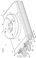
- FIG. 1 is a perspective explanatory view of a first embodiment of a rotary actuator.
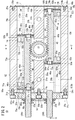
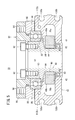
- FIG. 2 is a cross-sectional explanatory view of the rotary actuator shown in FIG.
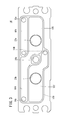
- FIG. 3 is a schematic side view of the first cover.
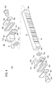
- FIG. 4 is an exploded perspective view of a rack and a piston constituting the rotary actuator of FIG.
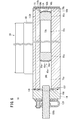
- FIG. 5 is a cross-sectional view taken along line VV in FIG. 6 is a cross-sectional view taken along line VI-VI in FIG.
- FIG. 7 is a cross-sectional explanatory view of a second embodiment of the rotary actuator.
- the rotary actuator according to the first embodiment of the present invention has a pair of linear operation mechanisms in parallel to the inside of the cylinder body, as will be described in detail below.
- Each linear actuation mechanism includes a set of pistons and a rack that is displaced by the reciprocating motion of the pistons. Further, a pinion that rotates by a reciprocating operation of the rack is provided, and the rotating operation of the pinion is configured to rotate, for example, a table provided outside the cylinder body.
- reference numeral 10 indicates a rotary actuator according to the first embodiment, and the rotary actuator 10 has a cylinder body 12 configured in a flat rectangular shape made of an aluminum alloy.
- the opening formed in one end surface orthogonal to the longitudinal direction of the cylinder body 12 is closed by the first cover 14, and the opening formed in the other end surface is closed by the second cover 16.
- the first cover 14 is a relatively thick metal plate, for example, a flat plate made of aluminum, and is separated from the cylinder body 12 by a predetermined distance. Ports 18a and 18b extending in the axial direction are provided. Further, through holes 20a, 20b, and 20c that are spaced apart by a predetermined distance are provided through stepped portions so as to sandwich the ports 18a and 18b, respectively.
- the fixing screws 22a, 22b, and 22c are screwed into the through holes 20a, 20b, and 20c, respectively, and the tip ends of the fixing screws 22a, 22b, and 22c are screw holes 21a provided near the opening of the cylinder body 12,
- the cylinder body 12 and the first cover 14 are integrated with each other by screwing the tip portions into 21b and 21c.
- Adjustment screw holes 23a and 23b into which adjustment screws 100a and 100b described later are screwed are provided between the port 18a and the through hole 20b and between the port 18b and the through hole 20b.
- the second cover 16 is mounted on the other end of the cylinder body 12 so as to be laminated on the gasket 24. As a result, the opening on the other end side of the cylinder body 12 is closed.
- the gasket 24 and the second cover 16 are fixed in an airtight manner, for example, by screws 26 a and 26 b screwed into screw holes 25 a and 25 b formed on the other end side of the cylinder body 12.
- first cylinder hole 28a and the second cylinder hole 28b sandwich the walls 30a and 30b inside the cylinder body 12 whose both ends in the longitudinal direction are closed by the first cover 14 and the second cover 16. Are formed substantially in parallel.
- the first cylinder hole 28a and the second cylinder hole 28b have a substantially quadrangular cross section as shown in FIG. By adopting such a cross-sectional shape, it is possible to suppress the occurrence of dead space when forming the first cylinder hole 28a and the second cylinder hole 28b with respect to the cylinder body 12 configured in a rectangular shape.
- the actuator 10 can be further downsized.
- the first wall portion 30a and the second wall portion 30b extend in the same straight line, and are spaced apart from each other by a predetermined distance at a substantially middle portion thereof.
- the first wall 30a is provided with an attachment hole 31a for attaching the rotary actuator 10
- the second wall 30b is similarly provided with an attachment hole 31b.
- End portions of the first wall portion 30a and the second wall portion 30b facing each other are formed in an arc shape, and a space 32 for accommodating a pinion 80 described later is formed by the two arcs.
- a passage 112a penetrating through the cylinder body 12 along its axial direction is formed at a position in the cylinder body 12 that is biased toward the table body 90 described later than the first cylinder hole 28a.
- a passage 112b penetrating the cylinder body 12 along the axial direction is formed at a position in the cylinder body 12 that is biased toward the table body 90 with respect to the second cylinder hole 28b.
- a first linear operation mechanism 40a is provided so as to be displaceable
- a second linear operation mechanism 40b is provided so as to be displaceable.
- first linear actuation mechanism 40a and the second linear actuation mechanism 40b have a paired structure, the first linear actuation mechanism 40a will be described in detail below, and the second linear actuation mechanism 40b will be described in detail. Detailed description is omitted.
- the first linear operation mechanism 40 a includes a rack 42.
- the cross section of the rack 42 is substantially square as shown in FIG. 5, and a plurality of teeth 44 are continuously provided on one side surface at equal intervals.
- the cross-sectional shape of the rack 42 is not limited to a square, and may be selected from a polygon, a circle, a semi-oval, and the like.
- the rack 42 is preferably made of iron, but is not limited to this and may be anything that is rich in rigidity.
- Pistons 48a and 48b are mounted using the recesses 46a and 46b provided at both ends of the rack 42, respectively.
- the piston 48a has a piston body 50a.
- the piston main body 50a includes a body 52a made of a thick rectangular body and an extending portion 54a thinner than the body 52a, and the body 52a and the extending portion 54a are defined as follows. Preferably, it is made of an integrally formed metal or resin.
- the body 52a and the extending portion 54a as a whole coincide with the shape of the first cylinder hole 28a, and the extending portion 54a side is disposed in the first cylinder hole 28a so as to face the first wall portion 30a.
- the extending portion 54a extends from the body 52a to the pinion 80 (see FIG.
- the first plate 56a is fixed to a smooth surface extending from the body 52a to the extending portion 54a, and a hollow rectangular seal member 58a is fitted to the stepped portion formed by the fixing of the first plate 56a.
- the sealing member 58a and the first plate 56a are stacked so that the second plate 60a covers one surface.
- the fixing pin 62a is inserted, and its tip is fixed to the recess 46a of the rack 42, and is integrated with the piston 48a and the rack 42.
- the piston 48 b is fixed to the other end side of the rack 42.
- the other piston body 50b constituting the piston 48b is provided with a cylindrical recess 72b.
- a cylindrical magnet 74 for position detection is inserted into the recess 72b.
- a concave portion 72a similar to the concave portion 72b may be provided in the piston body 50a on one side, and a cylindrical magnet (not shown) may be attached to the concave portion 72a.
- the extending portions 54a and 54b of the pistons 48a and 48b are fixed to both ends of the rack 42 constituting the first linear operating mechanism 40a, respectively, so that the rack is formed in the first cylinder hole 28a. 42 is arranged so as to be biased toward the pinion 80 side. Thereby, it is possible to form a sufficient space 73a between the bodies 52a and 52b of the pistons 48a and 48b, and between the side wall of the rack 42 and the first cylinder hole 28a. By utilizing this space 73a, a long magnet 74 as indicated by a broken line in FIG. 2 can be mounted according to the application desired by the user, if necessary. The same applies to the second linear actuation mechanism 40b side. In some cases, other members such as a wear ring and an absorber (both not shown) may be mounted on the rack 42 and the pistons 48a and 48b using the space 73a.
- the first cylinder hole 28a is divided into the space 73a, the first cylinder chamber 75a, and the second cylinder chamber 75b by pistons 48a and 48b. That is, the first cylinder chamber 75a is formed by the first cover 14 and the piston 48a, while the second cylinder chamber 75b is formed by the piston 48b and the second cover 16 (gasket 24). Similarly, as shown in FIG. 6, the second cylinder hole 28b is formed between the first cover 14 and the piston 48a, between the pistons 48a and 48b, and between the piston 48b and the second cover 16, respectively.
- the pinion 80 that rotates under the biasing action of the first and second linear operating mechanisms 40a and 40b will be described.
- the pinion 80 is disposed in a circular space 32 formed between the first wall portion 30a and the second wall portion 30b.
- the pinion 80 has a cylindrical shape having a space 81 in the central portion along the axial direction, and a first bearing 82 having a relatively small diameter is provided between the pinion 80 and the cylinder body 12. Yes.
- Above the portion that holds the first bearing 82 there are a plurality of teeth 84 that are engraved on the outer peripheral surface at equal intervals, and these teeth 84 mesh with the teeth 44 of the rack 42.
- a stepped portion 83 is provided on the top of the pinion 80, and a second bearing 86 having a diameter larger than that of the first bearing 82 is provided between the pinion 80 and the cylinder body 12 by using the stepped portion 83.
- a ring body 88 having a step is fitted on the outer peripheral surface of the second bearing 86.
- an annular table body 90 is fixed to the upper part of the pinion 80 via a plurality of bolts 92.
- the table body 90 is provided with a plurality of mounting holes 94 at equal intervals on the outside of the bolt 92, and a workpiece (not shown) is mounted using the bolt. Since it is configured as described above, it can be easily understood that the table main body 90 integrated with the pinion 80 by the bolt 92 rotates under the action of the bearings 82 and 86 by the rotation of the pinion 80.
- the adjusting screws 100a and 100b for regulating the stroke of the rack 42 that is, the displacement range of the first linear operating mechanism 40a and the second linear operating mechanism 40b that reciprocate inside the first cylinder hole 28a and the second cylinder hole 28b. Will be described.
- the adjustment screw 100a which is relatively long and has a screw portion formed on the outer peripheral portion thereof, is screwed into an adjustment screw hole 23a provided in the first cover 14, and the tip portion is screwed into the first linear portion. It faces the head of the fixing pin 62a of the operating mechanism 40a. Therefore, the position where the head of the fixing pin 62a abuts is regulated depending on the degree of screwing of the adjusting screw 100a into the adjusting screw hole 23a, thereby adjusting the stroke of the first linear operating mechanism 40a, that is, the rack 42. To. Since the adjustment screw 100b that regulates the operation range of the rack 42 on the second linear operation mechanism 40b side also adopts the same configuration as the adjustment screw 100a, detailed description thereof is omitted.
- the screwing positions of the adjusting screws 100a and 100b are firmly positioned by a stopper 120 that is rich in elasticity and has a U-shaped cross section.
- a first recess 104, a second recess 105, a third recess 106, and a fourth recess are formed on the surface of the first cover 14 facing the opening of the cylinder body 12 so as to be recessed from the surface.
- Recesses 107 are respectively formed.
- the first recess 104 communicates with the port 18a and faces the opening of the passage 112a (see FIG. 2).
- the second recess 105 faces the first cylinder chamber 75a (see FIG. 2) and communicates with the third recess 106 on the center side in the width direction of the first cover 14.
- the third recess 106 communicates with the port 18b and faces the opening of the passage 112b (see FIGS. 2 and 6).
- the fourth recess 107 faces the third cylinder chamber 76a (see FIGS. 2 and 6).
- a communication path 108 that connects the first recess 104 and the fourth recess 107 is formed inside the first cover 14. That is, in the first cover 14, the fluid can freely flow between the first recess 104 and the fourth recess 107, and the fluid can freely flow between the second recess 105 and the third recess 106. is there.
- first cover 14 and the cylinder body 12 are integrally provided along the contours (outer shapes) of the first recess 104, the second recess 105, the third recess 106, and the fourth recess 107.
- a gasket 109 is interposed.
- the cylinder body 12 is provided with a supply / exhaust port 110a communicating with the second cylinder chamber 75b, and the supply / exhaust port 110a communicates with the first recess 104 via a passage 112a. is doing.
- the cylinder body 12 is provided with an air supply / exhaust port 110b communicating with the fourth cylinder chamber 76b, and the air supply / exhaust port 110b communicates with the third recess 106 via a passage 112b.
- reference numerals 130a and 130b denote sensor grooves provided on the side surfaces in the longitudinal direction of the cylinder body 12, respectively.
- the rack 42 receives the displacement of the rack 42, that is, the magnetic lines of force of the magnets 74 mounted in the recesses 72a and 72b of the piston bodies 50a and 50b. This is for detecting the position of.
- the rotary actuator 10 according to the first embodiment is basically configured as described above, and the operation and effect thereof will be described next.
- a tube for supplying and discharging pressurized fluid, for example, compressed air, is connected to the ports 18a and 18b via a connector (not shown).
- a workpiece (not shown) is fixed with a bolt or the like. Therefore, in the initial state shown in FIG. 2, when compressed air is supplied from the port 18b, a part of the compressed air flows into the second recess 105 through the third recess 106 and enters the first cylinder chamber 75a. be introduced.
- the piston main body 50a on the first cover 14 side specifically, the head of the fixing pin 62a, the surface of the second plate 60a, the seal member 58a, etc. of one end side, that is, the first linear operating mechanism 40a. It becomes a pressure receiving portion and presses the rack 42 toward the other end side, that is, the second cover 16 side.
- the piston body 50b on the second cover 16 side becomes a pressure receiving portion, and presses the rack 42 toward the other end side, that is, the first cover 14 side.
- the remaining portion of the compressed air supplied from the port 18a is introduced into the second cylinder chamber 75b through the first recess 104, the passage 112a, and the supply / exhaust port 110a.
- the piston body 50b on the second cover 16 side serves as a pressure receiving portion, and presses the rack 42 toward the first cover 14 side.
- Such an operation is alternately repeated between the first linear operating mechanism 40a and the second linear operating mechanism 40b to rotate the pinion 80 forward and backward, and as a result, the table main body 90 also rotates forward and backward. That is, by rotating the table main body 90 connected to the pinion 80 via the bolt 92, the work mounted on the table main body 90 can be rotated, and the work can be used for machining, for example. .
- a pair of pistons 48a and 48b are fixed to both ends of the rack 42 in the first linear operation mechanism 40a and the second linear operation mechanism 40b, respectively.
- the body 52a constituting the piston 48a is formed of a relatively thick rectangular body, and a thin extending portion 54a is provided laterally (horizontal direction in the drawing) from the body 52a.
- the edge part of the rack 42 adheres to the level
- the piston 48b side has the same configuration. Therefore, the fluid pressure applied to the bodies 52a and 52b and the extending portions 54a and 54b is received with sufficient strength.
- a space 73a is formed between the piston bodies 50a and 50b.
- the space 73a can be used for various purposes such as mounting a long magnet 74 and disposing a wear ring.
- the space between the piston bodies 50a and 50b can be effectively utilized to ensure the degree of freedom of mounting the magnet 74, and extend from the bodies 52a and 52b.
- a sufficient pressure receiving area can be secured by the portions 54a and 54b. For this reason, the effect that the thrust required for the displacement operation
- the first cylinder hole 28a and the second cylinder hole 28b have a quadrangular cross section, the cylinder body 12 can be further flattened, and the height of the rotary actuator 10 can be kept small.
- the rotary actuator 200 according to the second embodiment is different from the rotary actuator 10 according to the first embodiment in that the number of the linear actuators 220 provided in the cylinder body 202 is one.
- the opening formed on one end surface orthogonal to the longitudinal direction of the thick cylinder body 202 is closed by the first cover 206, and the opening formed on the other end surface is the second cover. 208 is occluded.
- the first cover 206 is made of a relatively thick metal plate, and has a port 18a on one thick side surface.
- the second cover 208 is a plate-like body similar to the first cover 206 and includes a port 18b.
- a cylinder hole 210 is formed in the cylinder body 202 closed by the first cover 206 and the second cover 208.
- An arc-shaped recess 212 for accommodating the pinion 80 is formed in one thick wall portion 214 of the cylinder body 202.
- the pinion 80 is rotatably supported in a space formed by the cylinder hole 210 and the recess 212.
- a linear operation mechanism 220 is provided in the cylinder hole 210 so as to be freely displaceable.
- the piston main body 222 a has substantially the same shape as the vertical cross-sectional space of the cylinder hole 210.
- a proximity switch (not shown) for detecting the position of the piston main body 222b is provided on the thin wall portion 216 facing the thick wall portion 214 formed with the recess 212 of the cylinder body 202.
- the rotary actuator 200 according to the second embodiment is basically configured as described above, and the operation and effect thereof will be described next.
- a tube for supplying and discharging pressurized fluid, for example, compressed air, is connected to the ports 18a and 18b via a connector (not shown). Therefore, if compressed air is supplied from the port 18a, the piston body 222a on the first cover 206 side becomes a pressure receiving portion, and the rack 42 is pressed toward the second cover 208 side. As a result, the rack 42 is displaced toward the second cover 208, and the air in the cylinder chamber between the piston body 222b and the second cover 208 is compressed and exhausted from the port 18b to a tube (not shown).
- pressurized fluid for example, compressed air
- a relatively large space can be provided between the piston bodies 222a and 222b. Similar effects can be obtained.
- one of the two linear operation mechanisms provided in the first embodiment can be omitted. That is, further downsizing is achieved, and in particular, an effect is obtained that enables installation in a narrower space.
- the tip ends of the adjustment screws 100a and 100b are screwed into the first cylinder hole 28a and the second cylinder hole 28b from the adjustment screw holes 23a and 23b provided in the first cover 14, respectively. I decided to do it.
- the adjustment screw 100a is all accommodated in the first cylinder hole 28a, and its tip protrudes from the space 73a toward at least one of the first cylinder chamber 75a and the second cylinder chamber 75b. Also good.
- a screw hole may be provided in the body 52a of the piston 48a, and the adjustment screw 100a may be screwed into the screw hole. Accordingly, the piston 48a and the adjustment screw 100a can be fixed integrally, and the position where the tip of the adjustment screw 100a abuts on the first cover 14 can be regulated depending on the degree of screwing. As a result, the stroke of the first linear operating mechanism 40a, that is, the rack 42 is adjusted.
- the adjustment screw 100a When the tip of the adjustment screw 100a is protruded into the second cylinder chamber 75b, the adjustment screw 100a may be screwed into the body 52b of the piston 48b in the same manner as described above. As a result, the position where the tip of the adjustment screw 100a and the second cover 16 come into contact with each other is regulated, and the stroke of the rack 42 is adjusted.
- the adjustment screw 100b can also be disposed in the second cylinder hole 28b in the same manner as the adjustment screw 100a.
Landscapes
- Engineering & Computer Science (AREA)
- General Engineering & Computer Science (AREA)
- Mechanical Engineering (AREA)
- Physics & Mathematics (AREA)
- Fluid Mechanics (AREA)
- Chemical & Material Sciences (AREA)
- Analytical Chemistry (AREA)
- Actuator (AREA)
- Transmission Devices (AREA)
Abstract
Description
前記リニア作動機構は、
前記ピニオンと噛合する複数の歯が設けられたラックと、
前記ラックに設けられたピストンと、
を有し、
前記ピストンは前記シリンダ孔に対応する形状のピストン本体と前記ピストン本体に装着されるシール部材とを備え、前記ピストン本体はボディと前記ボディから前記ピニオン側に伸長する延在部とを有し、
前記ラックの両端部は、一組の前記ピストンのうち、前記延在部の前記ピニオン側に偏倚した部位に連結されるとともに、一組の前記ピストンの前記ボディ間に前記シリンダ孔と遮蔽された空間が形成されているロータリーアクチュエータが提供される。
Claims (6)
- ピニオン(80)を回転動作させるリニア作動機構(40a)と、前記リニア作動機構(40a)が変位自在に設けられるシリンダ孔(28a)が形成されたシリンダボディ(12)と、を備えるロータリーアクチュエータ(10)であって、
前記リニア作動機構(40a)は、
前記ピニオン(80)と噛合する複数の歯(44)が設けられたラック(42)と、
前記ラック(42)に設けられたピストン(48a、48b)と、
を有し、
前記ピストン(48a、48b)は前記シリンダ孔(28a)に対応する形状のピストン本体(50a、50b)と前記ピストン本体(50a、50b)に装着されるシール部材(58a)とを備え、前記ピストン本体(50a、50b)はボディ(52a、52b)と前記ボディ(52a、52b)から前記ピニオン(80)側に伸長する延在部(54a、54b)とを有し、
前記ラック(42)の両端部は、一組の前記ピストン(48a、48b)のうち、前記延在部(54a、54b)の前記ピニオン(80)側に偏倚した部位に連結されるとともに、一組の前記ピストン(48a、48b)の前記ボディ(52a、52b)間に前記シリンダ孔(28a)と遮蔽された空間(73a)が形成されていることを特徴とするロータリーアクチュエータ(10)。 - 請求項1記載のロータリーアクチュエータ(200)において、
前記シリンダボディ(202)は、1つの前記シリンダ孔(210)が形成され、
1つの前記シリンダ孔(210)に1つの前記リニア作動機構(220)が配設されることを特徴とするロータリーアクチュエータ(200)。 - 請求項1記載のロータリーアクチュエータ(10)において、
前記シリンダボディ(12)は、平行に一対の前記シリンダ孔(28a、28b)が形成され、
一対の前記シリンダ孔(28a、28b)のそれぞれに一対の前記リニア作動機構(40a、40b)が配設されることを特徴とするロータリーアクチュエータ(10)。 - 請求項1記載のロータリーアクチュエータ(10)において、
前記ピストン本体(50a、50b)は、前記ボディ(52a、52b)と前記延在部(54a、54b)とが一体成形されて構成されることを特徴とするロータリーアクチュエータ(10)。 - 請求項1記載のロータリーアクチュエータ(10)において、
前記ボディ(52a、52b)の少なくとも一方は、前記空間(73a)に対面する端部に、前記ラック(42)の位置を検出するためのマグネット(74)が配設されることを特徴とするロータリーアクチュエータ(10)。 - 請求項1記載のロータリーアクチュエータ(10)において、
前記シリンダボディ(12)は、外形が略四角形状であり、
前記シリンダ孔(28a、28b)は、横断面略四角形状であることを特徴とするロータリーアクチュエータ(10)。
Priority Applications (6)
| Application Number | Priority Date | Filing Date | Title |
|---|---|---|---|
| MX2017014342A MX2017014342A (es) | 2015-05-11 | 2016-03-14 | Accionador giratorio. |
| US15/572,816 US10590964B2 (en) | 2015-05-11 | 2016-03-14 | Rotary actuator |
| BR112017024040-8A BR112017024040A2 (ja) | 2015-05-11 | 2016-03-14 | Rotary actuator |
| EP16792425.7A EP3296575B1 (en) | 2015-05-11 | 2016-03-14 | Rotary actuator |
| KR1020177035587A KR102010350B1 (ko) | 2015-05-11 | 2016-03-14 | 로터리 액추에이터 |
| RU2017142698A RU2683347C1 (ru) | 2015-05-11 | 2016-03-14 | Поворотный исполнительный механизм |
Applications Claiming Priority (2)
| Application Number | Priority Date | Filing Date | Title |
|---|---|---|---|
| JP2015096588A JP6252952B2 (ja) | 2015-05-11 | 2015-05-11 | ロータリーアクチュエータ |
| JP2015-096588 | 2015-05-11 |
Publications (1)
| Publication Number | Publication Date |
|---|---|
| WO2016181700A1 true WO2016181700A1 (ja) | 2016-11-17 |
Family
ID=57248016
Family Applications (1)
| Application Number | Title | Priority Date | Filing Date |
|---|---|---|---|
| PCT/JP2016/057898 Ceased WO2016181700A1 (ja) | 2015-05-11 | 2016-03-14 | ロータリーアクチュエータ |
Country Status (9)
| Country | Link |
|---|---|
| US (1) | US10590964B2 (ja) |
| EP (1) | EP3296575B1 (ja) |
| JP (1) | JP6252952B2 (ja) |
| KR (1) | KR102010350B1 (ja) |
| BR (1) | BR112017024040A2 (ja) |
| MX (1) | MX2017014342A (ja) |
| RU (1) | RU2683347C1 (ja) |
| TW (1) | TWI696764B (ja) |
| WO (1) | WO2016181700A1 (ja) |
Cited By (2)
| Publication number | Priority date | Publication date | Assignee | Title |
|---|---|---|---|---|
| WO2019122280A1 (de) * | 2017-12-22 | 2019-06-27 | Schwing Gmbh | Hydraulischer drehantrieb |
| CN111451955A (zh) * | 2020-04-09 | 2020-07-28 | 济南鑫光试验机制造有限公司 | 一种分体集成自同步平推夹头 |
Families Citing this family (6)
| Publication number | Priority date | Publication date | Assignee | Title |
|---|---|---|---|---|
| ES2902788T3 (es) | 2015-07-22 | 2022-03-29 | Bucher Hydraulics Gmbh | Accionamiento lineal eléctrico compacto para una cremallera, en particular de una válvula hidráulica, y procedimiento para su montaje |
| USD841705S1 (en) * | 2015-10-09 | 2019-02-26 | Smc Corporation | Rotary actuator |
| USD960327S1 (en) * | 2019-01-22 | 2022-08-09 | Air Torque S.P.A. | Fluidodynamic actuator |
| FI129391B (fi) * | 2020-05-14 | 2022-01-31 | Ponsse Oyj | Paineväliainesylinteri ja menetelmä hammastangon liikuttamiseksi sekä työkone |
| TWI841194B (zh) * | 2023-01-13 | 2024-05-01 | 伍隆國際有限公司 | 齒狀結構的傳動裝置 |
| CN116498792A (zh) * | 2023-05-09 | 2023-07-28 | 浙江互利模具有限公司 | 一种预防气液混合的气液联动执行机构 |
Citations (2)
| Publication number | Priority date | Publication date | Assignee | Title |
|---|---|---|---|---|
| JP2010071390A (ja) * | 2008-09-18 | 2010-04-02 | Smc Corp | ダブルラック・ピニオン式揺動装置 |
| JP2012251602A (ja) * | 2011-06-03 | 2012-12-20 | Smc Corp | ピストン組立体、流体圧シリンダ及びピストン組立体の製造方法 |
Family Cites Families (19)
| Publication number | Priority date | Publication date | Assignee | Title |
|---|---|---|---|---|
| US2844127A (en) * | 1955-03-03 | 1958-07-22 | Steiner Carl | Fluid pressure torque converter |
| US3288035A (en) * | 1962-08-06 | 1966-11-29 | Pleiger Maschf Paul | Motion transmitting apparatus |
| US3156160A (en) * | 1963-02-15 | 1964-11-10 | Flo Tork Inc | Actuator |
| US3338140A (en) * | 1965-08-16 | 1967-08-29 | John M Sheesley | Actuator |
| US5076090A (en) * | 1989-04-05 | 1991-12-31 | Utica Enterprises, Inc. | Dual action equalizing apparatus |
| US5024116A (en) * | 1989-06-08 | 1991-06-18 | Kraft Brett W | Modular rotary actuator |
| US5189923A (en) * | 1992-01-24 | 1993-03-02 | Bimba Manufacturing Company | Antibacklash rack assembly |
| RU2073093C1 (ru) * | 1993-04-19 | 1997-02-10 | Липовский Марат Исаакович | Гидродвигатель |
| DE4343184A1 (de) * | 1993-12-17 | 1995-06-22 | Montech Ag | Antrieb zum Drehen einer Ritzelwelle |
| US5427012A (en) * | 1994-02-25 | 1995-06-27 | Sprague Devices, Inc. | Electronically controlled fluid powered motor |
| JP3729724B2 (ja) * | 2000-10-30 | 2005-12-21 | 株式会社コガネイ | 揺動形アクチュエータ |
| JP4264918B2 (ja) * | 2000-12-05 | 2009-05-20 | Smc株式会社 | 開閉チャック |
| JP3701576B2 (ja) * | 2001-04-10 | 2005-09-28 | Smc株式会社 | ダブルラック・ピニオン式揺動装置 |
| RU2207448C2 (ru) * | 2001-06-13 | 2003-06-27 | Северо-Западный научно-исследовательский институт механизации и электрификации сельского хозяйства | Гидродвигатель |
| JP4376780B2 (ja) * | 2002-06-14 | 2009-12-02 | 株式会社キッツ | 空気圧アクチュエータ |
| JP4994020B2 (ja) | 2006-12-21 | 2012-08-08 | 株式会社コガネイ | ロータリアクチュエータ |
| JP5464408B2 (ja) * | 2009-05-18 | 2014-04-09 | Smc株式会社 | 流体圧シリンダ |
| RU2446322C2 (ru) * | 2010-06-23 | 2012-03-27 | Открытое акционерное общество "Ракетно-космическая корпорация "Энергия" имени С.П. Королева" | Исполнительный механизм |
| US9388833B2 (en) * | 2012-04-16 | 2016-07-12 | Zaytran, Inc. | Compact linear actuator with anti-rotation device |
-
2015
- 2015-05-11 JP JP2015096588A patent/JP6252952B2/ja active Active
-
2016
- 2016-03-14 RU RU2017142698A patent/RU2683347C1/ru active
- 2016-03-14 BR BR112017024040-8A patent/BR112017024040A2/ja active Search and Examination
- 2016-03-14 EP EP16792425.7A patent/EP3296575B1/en not_active Not-in-force
- 2016-03-14 US US15/572,816 patent/US10590964B2/en active Active
- 2016-03-14 KR KR1020177035587A patent/KR102010350B1/ko active Active
- 2016-03-14 MX MX2017014342A patent/MX2017014342A/es unknown
- 2016-03-14 WO PCT/JP2016/057898 patent/WO2016181700A1/ja not_active Ceased
- 2016-03-29 TW TW105109823A patent/TWI696764B/zh active
Patent Citations (2)
| Publication number | Priority date | Publication date | Assignee | Title |
|---|---|---|---|---|
| JP2010071390A (ja) * | 2008-09-18 | 2010-04-02 | Smc Corp | ダブルラック・ピニオン式揺動装置 |
| JP2012251602A (ja) * | 2011-06-03 | 2012-12-20 | Smc Corp | ピストン組立体、流体圧シリンダ及びピストン組立体の製造方法 |
Cited By (3)
| Publication number | Priority date | Publication date | Assignee | Title |
|---|---|---|---|---|
| WO2019122280A1 (de) * | 2017-12-22 | 2019-06-27 | Schwing Gmbh | Hydraulischer drehantrieb |
| US11535497B2 (en) | 2017-12-22 | 2022-12-27 | Schwing Gmbh | Hydraulic rotary drive |
| CN111451955A (zh) * | 2020-04-09 | 2020-07-28 | 济南鑫光试验机制造有限公司 | 一种分体集成自同步平推夹头 |
Also Published As
| Publication number | Publication date |
|---|---|
| EP3296575B1 (en) | 2020-09-02 |
| JP6252952B2 (ja) | 2017-12-27 |
| RU2683347C1 (ru) | 2019-03-28 |
| EP3296575A4 (en) | 2018-12-05 |
| MX2017014342A (es) | 2018-03-23 |
| KR20180004797A (ko) | 2018-01-12 |
| TWI696764B (zh) | 2020-06-21 |
| US20180087544A1 (en) | 2018-03-29 |
| US10590964B2 (en) | 2020-03-17 |
| JP2016211673A (ja) | 2016-12-15 |
| TW201702489A (zh) | 2017-01-16 |
| BR112017024040A2 (ja) | 2018-07-24 |
| KR102010350B1 (ko) | 2019-10-21 |
| EP3296575A1 (en) | 2018-03-21 |
Similar Documents
| Publication | Publication Date | Title |
|---|---|---|
| JP6252952B2 (ja) | ロータリーアクチュエータ | |
| JP5704528B2 (ja) | リニアアクチュエータ | |
| TWI565881B (zh) | 旋轉致動器 | |
| CN101676571B (zh) | 双齿条小齿轮式摇摆装置 | |
| JP4994020B2 (ja) | ロータリアクチュエータ | |
| JP4525155B2 (ja) | リニアアクチュエータ | |
| JP4992151B2 (ja) | リニアアクチュエータ | |
| EP2822739A1 (en) | Device for connecting a tool to a robot arm | |
| KR101866813B1 (ko) | 유압 실린더 | |
| JP5574152B2 (ja) | リニアアクチュエータ | |
| US10399211B2 (en) | Chuck apparatus | |
| US6910409B2 (en) | Oscillating actuator | |
| JP4702663B2 (ja) | アクチュエータの軸受支持構造 | |
| JP2008296347A (ja) | 回転割出装置 | |
| JP2021014888A (ja) | 流体圧アクチュエータ | |
| JPH10318209A (ja) | ロッドレスシリンダ | |
| JP2002130208A (ja) | 揺動形アクチュエータ | |
| JP5533231B2 (ja) | リニアアクチュエータ | |
| JP2003120608A (ja) | 揺動アクチュエータ | |
| JP2002130209A (ja) | 揺動形アクチュエータ | |
| SE530925C2 (sv) | Excentrisk radialkolvpump samt excentrisk radialkolvmotor | |
| JPH11344031A (ja) | リニアガイド装置 | |
| JP2000283114A (ja) | 流体圧アクチュエータ | |
| JP2016056934A (ja) | 流体圧シリンダ及びアクチュエータ |
Legal Events
| Date | Code | Title | Description |
|---|---|---|---|
| 121 | Ep: the epo has been informed by wipo that ep was designated in this application |
Ref document number: 16792425 Country of ref document: EP Kind code of ref document: A1 |
|
| WWE | Wipo information: entry into national phase |
Ref document number: MX/A/2017/014342 Country of ref document: MX |
|
| WWE | Wipo information: entry into national phase |
Ref document number: 15572816 Country of ref document: US |
|
| NENP | Non-entry into the national phase |
Ref country code: DE |
|
| WWE | Wipo information: entry into national phase |
Ref document number: 2017142698 Country of ref document: RU |
|
| ENP | Entry into the national phase |
Ref document number: 20177035587 Country of ref document: KR Kind code of ref document: A |
|
| REG | Reference to national code |
Ref country code: BR Ref legal event code: B01A Ref document number: 112017024040 Country of ref document: BR |
|
| ENP | Entry into the national phase |
Ref document number: 112017024040 Country of ref document: BR Kind code of ref document: A2 Effective date: 20171108 |