WO2016181708A1 - Détecteur de rayonnement, et dispositif de tomographie par rayonnement le comprenant - Google Patents
Détecteur de rayonnement, et dispositif de tomographie par rayonnement le comprenant Download PDFInfo
- Publication number
- WO2016181708A1 WO2016181708A1 PCT/JP2016/058851 JP2016058851W WO2016181708A1 WO 2016181708 A1 WO2016181708 A1 WO 2016181708A1 JP 2016058851 W JP2016058851 W JP 2016058851W WO 2016181708 A1 WO2016181708 A1 WO 2016181708A1
- Authority
- WO
- WIPO (PCT)
- Prior art keywords
- scintillator
- photodetector
- adhesive sheet
- radiation detector
- light guide
- Prior art date
- Legal status (The legal status is an assumption and is not a legal conclusion. Google has not performed a legal analysis and makes no representation as to the accuracy of the status listed.)
- Ceased
Links
Images







Classifications
-
- G—PHYSICS
- G01—MEASURING; TESTING
- G01T—MEASUREMENT OF NUCLEAR OR X-RADIATION
- G01T1/00—Measuring X-radiation, gamma radiation, corpuscular radiation, or cosmic radiation
- G01T1/16—Measuring radiation intensity
- G01T1/161—Applications in the field of nuclear medicine, e.g. in vivo counting
-
- G—PHYSICS
- G01—MEASURING; TESTING
- G01T—MEASUREMENT OF NUCLEAR OR X-RADIATION
- G01T1/00—Measuring X-radiation, gamma radiation, corpuscular radiation, or cosmic radiation
- G01T1/16—Measuring radiation intensity
- G01T1/20—Measuring radiation intensity with scintillation detectors
-
- G—PHYSICS
- G01—MEASURING; TESTING
- G01T—MEASUREMENT OF NUCLEAR OR X-RADIATION
- G01T1/00—Measuring X-radiation, gamma radiation, corpuscular radiation, or cosmic radiation
- G01T1/16—Measuring radiation intensity
- G01T1/20—Measuring radiation intensity with scintillation detectors
- G01T1/202—Measuring radiation intensity with scintillation detectors the detector being a crystal
Definitions
- the present invention relates to a radiation detector including a scintillator that converts radiation into fluorescence and a radiation tomography apparatus including the same.
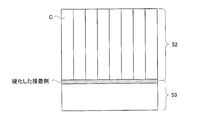
- Such a radiation detector includes a scintillator 52 configured by vertically and horizontally arranging scintillator crystals C having a rectangular parallelepiped shape.
- the scintillator crystal C is made of a material that converts radiation into fluorescence when the radiation enters.
- the fluorescence generated in the scintillator 52 is detected by a photodetector 53 optically coupled to the scintillator 52 (see, for example, Patent Document 1).
- the radiation detector according to the present invention is configured by optically coupling a scintillator 52 and a photodetector 53, which are configured by integrating a scintillator crystal C.
- a liquid adhesive is used to couple the scintillator 52 and the photodetector 53 together. This adhesive is injected between the scintillator 52 and the photodetector 53 and hardens to become an adhesive layer.
- the adhesive layer is located between the scintillator 52 and the photodetector 53, and is integrated by fixing them together.
- the conventional radiation detector has the following problems. That is, according to the present invention, maintenance has become difficult.
- the conventional radiation detector is not configured to be disassembled.
- the failure of the radiation detector is often caused by either the scintillator 52 or the photodetector 53 (particularly the photodetector 53). Therefore, even if the radiation detector breaks down, it may operate normally again when the scintillator 52 or the photodetector 53 is replaced with a new one.
- the scintillator 52 and the photodetector 53 are firmly fixed by a cured adhesive. Therefore, it may happen that the scintillator 52 or the photodetector 53 that has not failed is damaged by trying to force the scintillator 52 and the photodetector 53 to be peeled off.
- the conventional radiation detector does not take into account the point of reusing each component. Each part is firmly integrated, so that parts cannot be replaced or repaired. Therefore, when one of the components constituting the radiation detector does not operate normally, the radiation detector must be discarded. Such a situation increases the cost of maintenance of the apparatus equipped with the radiation detector.
- the present invention has been made in view of such circumstances, and an object of the present invention is to provide a radiation detector that is easy to maintain by adopting a structure that can be disassembled.
- the radiation detector according to the present invention includes (A) a scintillator in which scintillator crystals that convert radiation into fluorescence are arranged vertically and horizontally, (B) a photodetector that detects fluorescence, and (C1). A pressure-sensitive adhesive sheet that separably and optically couples the scintillator and the photodetector is provided.
- the radiation detector of the present invention maintenance can be facilitated by adopting a configuration in which the radiation detector can be disassembled. That is, in the radiation detector of the present invention, the scintillator and the light detector are separable and optically coupled by the adhesive sheet. Therefore, if a force is applied to the radiation detector so that the scintillator and the photodetector are separated from each other, the adhesive sheet is peeled off and the function of integrating the scintillator and the photodetector is not achieved. Thus, the radiation detector of the present invention can physically separate the scintillator and the photodetector.
- the present invention is set so that the adhesive force of the adhesive sheet is smaller than the force necessary to break the scintillator.
- the scintillator is formed by integrating scintillator crystals. When an excessive force is applied, the scintillator crystals are physically separated from each other, or the scintillator crystals are cracked.
- the adhesive sheet when a force is applied to the radiation detector so that the scintillator and the photodetector are separated from each other, the adhesive sheet is peeled off and separated from the photodetector before the scintillator collapses. Therefore, according to the configuration of the present invention, the intact scintillator separated from the photodetector can be reused.
- the above-described radiation detector may be configured such that the shape of the surface coupled to the photodetector in the scintillator is the shape of the surface coupled to the scintillator in the photodetector.
- (S) the surface of the adhesive sheet adhered to the scintillator is adhered to the scintillator in a state where the surface of the scintillator is adhered to the surface of the adhesive sheet
- the surface adhered to the photodetector of the sheet may be configured to adhere to the photodetector in a state of being deformed into the shape of the surface to which the adhesive sheet in the photodetector is adhered.
- the above-described configuration specifically describes the case where the scintillator is coupled to the photodetector without using the light guide.
- the shape of the surface coupled to the scintillator in the photodetector may not be a flat surface. Therefore, for example, if the shape of the surface coupled to the photodetector in the scintillator is the shape of the surface coupled to the scintillator in the photodetector, the two members are securely bonded together. Further, if the pressure-sensitive adhesive sheet is adhered to both members in a state of being deformed so as to absorb the difference in shape between the two members, the two members are securely bonded together.
- the radiation detector according to the present invention includes (D4) a light guide that is optically coupled to the scintillator via an optical adhesive and allows fluorescence to pass therethrough.
- the adhesive sheet is a combination of the scintillator and the light guide.
- the body and the photodetector can also be configured to be separable and optically coupled.
- the above-described configuration is a case where a light guide is provided at a position sandwiched between the scintillator and the photodetector, and in particular, an adhesive sheet is disposed between the light guide and the photodetector.
- the configuration is described.
- the above-described configuration is set so that the adhesive force of the adhesive sheet is smaller than the force necessary to break the light guide. If an excessive force is applied to the light guide, the parts constituting the light guide are physically separated from each other, or the light guide is cracked.
- the adhesive sheet is peeled off and separated from the photodetector before the light guide collapses. Therefore, according to the configuration of the present invention, the intact light guide separated from the photodetector can be reused.
- the radiation detector according to the present invention may have a configuration in which the shape of the surface coupled to the photodetector in the light guide is the shape of the surface coupled to the light guide in the photodetector.
- (L) the surface of the pressure-sensitive adhesive sheet that is adhered to the light guide is adhered to the light guide in a state where the surface of the light guide is adhered to the light guide
- H) The surface of the adhesive sheet that is adhered to the photodetector can also be configured to adhere to the photodetector in a state of being deformed into the shape of the surface to which the adhesive sheet of the photodetector is adhered.
- the above-described configuration more specifically describes the configuration including the light guide.
- the shape of the surface coupled to the scintillator in the photodetector may not be a flat surface. Therefore, for example, if the shape of the surface coupled to the photodetector in the light guide is the shape of the surface to which the light guide in the photodetector is coupled, both members are securely coupled together. Further, if the pressure-sensitive adhesive sheet is adhered to both members in a state of being deformed so as to absorb the difference in shape between the two members, the two members are securely bonded together.
- the radiation detector according to the present invention includes (D7) a light guide that is optically coupled to the photodetector through an optical adhesive and allows fluorescence to pass therethrough, and (C7) the adhesive sheet includes a scintillator and a light guide. It is also possible to separate and optically couple the optical detector combination.
- the above configuration is a case where a light guide is provided at a position sandwiched between the scintillator and the photodetector, and in particular, a configuration in which an adhesive sheet is disposed between the light guide and the scintillator. Describes. As described above, the present invention can employ various configurations.
- the pressure-sensitive adhesive sheet is a double-sided pressure-sensitive adhesive sheet provided with a strong adhesive surface and a weak adhesive surface.
- the adhesive sheet is a silicon-based adhesive sheet.
- the above-described configuration shows a specific configuration of the present invention. If the pressure-sensitive adhesive sheet is a silicon-based pressure-sensitive adhesive sheet, the scintillator can be configured more reliably.
- the radiation detector of the present invention maintenance is facilitated by adopting a configuration in which the radiation detector can be disassembled. That is, in the radiation detector of the present invention, the scintillator and the light detector are separable and optically coupled by the adhesive sheet. Therefore, if a force is applied to the radiation detector so that the scintillator and the photodetector are separated from each other, the adhesive sheet is peeled off and the function of integrating the scintillator and the photodetector is not achieved. Thus, the radiation detector of the present invention can physically separate the scintillator and the photodetector.
- FIG. 6 is a plan view for explaining a scintillator according to Embodiment 2.
- FIG. 6 is a plan view for explaining a radiation detector according to Embodiment 2.
- FIG. 6 is a plan view illustrating an example of a radiation detector according to Embodiment 2.
- FIG. 6 is a plan view illustrating an example of a radiation detector according to Embodiment 2.
- FIG. 6 is a plan view illustrating an example of a radiation detector according to Embodiment 2.
- FIG. 6 is a plan view illustrating an example of a radiation detector according to Embodiment 2.
- FIG. It is a top view explaining 1 modification of this invention. It is a schematic diagram explaining the radiation detector of a conventional structure.
- Gamma rays correspond to the radiation of the present invention.
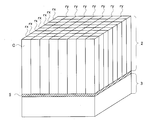
- the radiation detector 1 is generated from a scintillator 2 in which scintillator crystals C that convert ⁇ -rays into fluorescence are arranged vertically and horizontally and a scintillator 2 provided on the lower surface of the scintillator 2. And a photodetector 3 for detecting fluorescence.
- elongated scintillator crystals C are arranged in a two-dimensional matrix of 8 ⁇ 8 in the height direction, and a total of 64 scintillator crystals C are provided.
- the scintillator crystal C is composed of LGSO (Lu, Gd) 2 SiO 5 containing a cerium element, and has a characteristic of emitting fluorescence when ⁇ rays are incident. Instead of LGSO, the scintillator crystal C may be made of other materials such as GSO (Gd 2 SiO 5 ). The scintillator crystal C converts ⁇ rays into fluorescence.
- the scintillator 2 includes a reflector rx extending in the horizontal direction and a reflector ry extending in the vertical direction.
- the reflector rx is provided between the scintillator crystals C adjacent from the vertical direction, and the reflector ry is provided between the scintillator crystals C adjacent from the horizontal direction. Therefore, the scintillator crystals C adjacent to each other are separated by either the reflection plate rx or the reflection plate ry.
- the reflectors rx and ry are made of a material such as an ESR (Enhanced Specular Reflector) film that reflects fluorescence.
- the scintillator crystal C and the reflector ry are integrated by a transmission material t that transmits fluorescence.
- the transmissive material t is configured by curing a liquid adhesive poured into the gap between the scintillator crystal C and the reflector ry.
- the scintillator crystal C and the reflector ry are not separated from each other by the transmissive material t.
- the transmitting material t has a function of maintaining the shape of the scintillator 52.
- FIG. 2 illustrates the side surface of the scintillator 2 where the scintillator crystals C and the reflector ry arranged in the lateral direction are integrated by the transmission material t.
- the side surface in which the scintillator crystals C arranged in the vertical direction and the reflection plate rx are integrated by the transmission material t has the same configuration as in FIG.
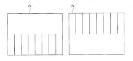
- FIG. 3 illustrates the reflectors rx and ry.
- the reflector rx has a plurality of grooves extending in the height direction. All of these grooves extend from the bottom of the reflector rx.
- the reflector ry also has a plurality of grooves extending in the height direction. All of these grooves extend from the upper part of the reflector ry.
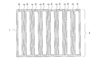
- the reflection plate rx and the reflection plate ry constitute a reflection plate frame as shown in FIG. 4 by fitting the grooves to each other.
- the reflector frame is composed of seven reflectors rx extending in the horizontal direction and seven reflectors ry extending in the vertical direction.
- the reflector frame body has a cell that houses the scintillator crystal C.
- the scintillator 2 is configured by integrating the reflector frame shown in FIG. 4 with each of the scintillator crystals C via a transmission material t.
- FIG. 5 shows an incident surface on which the fluorescence in the photodetector 3 is incident.
- semiconductor light receiving elements 3a for detecting fluorescence are arranged vertically and horizontally.
- the semiconductor light receiving elements 3a are arranged in a two-dimensional matrix of 8 ⁇ 8, and a total of 64 semiconductor light receiving elements 3a are provided.
- the pressure-sensitive adhesive sheet 5 is a double-sided pressure-sensitive adhesive sheet, one surface of the pressure-sensitive adhesive sheet 5 is adhered to the emission surface of the scintillator 2 and the other surface is adhered to the photodetector 3. That is, the exit surface for emitting fluorescence in the scintillator 2 and the entrance surface in the photodetector 3 are connected by the adhesive sheet 5 provided at a position sandwiched between the surfaces.
- the pressure-sensitive adhesive sheet 5 is transparent and has a property of allowing fluorescence to pass. Therefore, the scintillator 2 and the photodetector 3 are optically coupled via the adhesive sheet 5.
- the adhesive sheet 5 is a transparent silicone adhesive sheet.
- the pressure-sensitive adhesive sheet 5 is a double-sided pressure-sensitive adhesive sheet 5 having a surface having a strong adhesive force and a surface having a weak adhesive force.
- the surface of the pressure-sensitive adhesive sheet 5 having the strong adhesive force is positioned on the scintillator 2 side, and the surface of the pressure-sensitive adhesive sheet 5 having the weak adhesive force is positioned on the photodetector 3 side.
- the surface of the pressure-sensitive adhesive sheet 5 having the stronger adhesive force can be disposed on the photodetector 3 side, and the surface of the pressure-sensitive adhesive sheet 5 having the weaker adhesive force can be disposed on the scintillator 2 side.
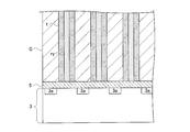
- FIG. 6 shows a state in which the adhesive sheet 5 is adhered to the scintillator 2 and the photodetector 3.
- the pressure-sensitive adhesive sheet 5 is adhered to the lower end surface (outgoing surface) of the scintillator 2 that is a flat surface.
- the surface of the adhesive sheet 5 opposite to the scintillator 2 side is attached to the semiconductor light receiving element 3 a on the incident surface of the photodetector 3.
- the pressure-sensitive adhesive sheet 5 is attached to the entire incident surface of the photodetector 3.
- Each of the scintillator crystals C constituting the scintillator 2 and each of the semiconductor light receiving elements 3a of the photodetector 3 are optically coupled on a one-to-one basis.
- FIG. 6 shows a configuration in which a transmissive material is not provided at the lower end of the scintillator 2 so that the boundary between the scintillator 2 and the adhesive sheet 5 can be easily understood. Such circumstances also apply to FIGS. 7, 8, and 16.
- the adhesive sheet 5 is adhered to the lower end of the scintillator crystal C constituting the scintillator 2 and the lower end portion of the reflector ry.
- FIG. 6 illustrates the side surface of the scintillator 2 on which the scintillator crystals C arranged in the lateral direction are isolated by the reflector ry.
- the side surfaces of the scintillator 2 the side surfaces in which the scintillator crystals C arranged in the vertical direction are isolated by the reflecting plate rx have the same configuration as in FIG.
- the manner in which the adhesive sheet 5 adheres to the lower end of the reflector rx is the same.
- the radiation detector of the present invention is characterized by the adhesive sheet 5. That is, the pressure-sensitive adhesive sheet 5 of the present invention combines the scintillator 2 and the photodetector 3 so as to be disassembled. When the scintillator 2 and the photodetector 3 are to be peeled off from each other, the adhesive sheet 5 resists the force and tries to continue the adhesion. When the force for peeling off the pressure-sensitive adhesive sheet 5 is gradually increased, the pressure-sensitive adhesive sheet 5 cannot withstand the applied force, and the pressure-sensitive adhesive sheet 5 is peeled off from the scintillator 2 or the photodetector 3.
- the adhesive sheet 5 that has combined the scintillator 2 and the photodetector 3 does not function, and the scintillator 2 and the photodetector 3 are separated.
- the force required to peel off the adhesive sheet 5 from the adhesive target is determined by the adhesive strength of the adhesive sheet 5.
- the force required to peel off the adhesive sheet 5 from the adhesion target will be referred to as adhesive force.
- the pressure-sensitive adhesive force of the pressure-sensitive adhesive sheet 5 is set to be weaker than the binding force of the transmission material t constituting the scintillator 2.
- the scintillator 2 is bent from the scintillator crystal or the reflectors rx and ry because of the force applied by the transmission material t constituting the scintillator 2. There is no end. That is, the adhesive force that is a force necessary to peel off the adhesive sheet 5 is set to be smaller than a force necessary to break the scintillator 2. In addition, the adhesive force, which is a force necessary for peeling off the adhesive sheet 5, is set to be smaller than a force necessary for damaging the photodetector 3.
- the adhesive strength of the surface of the adhesive sheet 5 adhered to the scintillator 2 and the adhesive strength of the surface adhered to the photodetector 3 are different from each other.
- the adhesive force on the scintillator side surface of the adhesive sheet 5 can be made stronger than the adhesive force on the photodetector side.
- FIG. 7 shows a state when the adhesive sheet 5 is peeled off by applying force. If the adhesive force on the scintillator side surface of the adhesive sheet 5 is made stronger than the adhesive force on the photodetector side, the adhesive sheet 5 is peeled off from the photodetector 3 in a state of being attached to the scintillator 2. When the adhesive sheet 5 is peeled off, the entire area of the adhesive sheet 5 tends to remain on the scintillator 2 side by making the adhesive force different.
- the pressure-sensitive adhesive force of the pressure-sensitive adhesive sheet 5 is made smaller than the force necessary to break the pressure-sensitive adhesive sheet 5, the pressure-sensitive adhesive sheet 5 will not be broken when the pressure-sensitive adhesive sheet 5 is peeled off from the scintillator 2, and the pressure-sensitive adhesive sheet 5 It becomes easy to remove from the scintillator 2.
- FIG. 8 shows a state where the adhesive sheet 5 remaining on the scintillator 2 is peeled off. At this time, the pressure-sensitive adhesive sheet 5 is peeled off from the scintillator 2 while maintaining physical integrity without being broken.
- the scintillator 2 thus separated from the photodetector 3 is intact and can be reused as a radiation detector.
- the scintillator 2 is optically coupled to a new or repaired photodetector 3 in place of the failed photodetector 3.
- a new adhesive sheet 5 is adhered between the scintillator 2 and the photodetector 3.
- the adhesive strength may be weakened. If a new adhesive sheet 5 is used when the scintillator 2 and the photodetector 3 are optically coupled, the coupling force between the scintillator 2 and the photodetector 3 can be secured.
- the radiation detector 1 can be disassembled. That is, in the radiation detector 1 of the present invention, the scintillator 2 and the photodetector 3 are separable and optically coupled by the adhesive sheet 5. Therefore, if a force is applied to the radiation detector 1 so that the scintillator 2 and the photodetector 3 are separated from each other, the adhesive sheet 5 is peeled off, and the function of integrating the scintillator 2 and the photodetector 3 is not achieved. Thus, the radiation detector 1 of the present invention can physically separate the scintillator 2 and the photodetector 3.
- the adhesive sheet 5 is configured to detachably couple the scintillator 2 and the photodetector 3. It is set so that the adhesive force of the adhesive sheet 5 is smaller than the force required to damage the scintillator 2.
- the scintillator 2 is configured by integrating scintillator crystals, and when an excessive force is applied, the scintillator crystals are physically separated from each other, or the scintillator crystals are cracked.
- the adhesive sheet 5 is peeled off and separated from the photodetector 3 before the scintillator 2 collapses. To do. Therefore, according to the configuration of the present invention, the intact scintillator 2 separated from the photodetector 3 can be reused.
- the shape of the surface coupled to the scintillator 2 in the photodetector 3 may not be a flat surface. Therefore, for example, if the shape of the surface coupled to the photodetector 3 in the scintillator 2 is the shape of the surface coupled to the scintillator 2 in the photodetector 3, both members are coupled in a state of being in close contact with each other. Is done. Moreover, if the adhesive sheet 5 adheres to both members in a state of being deformed so as to absorb the difference in shape between the two members, both members are securely bonded together.
- the pressure-sensitive adhesive sheet 5 when the pressure-sensitive adhesive sheet 5 is peeled off, the pressure-sensitive adhesive sheet 5 tends to remain on the scintillator 2 to which the entire surface has a strong adhesive force. Therefore, the adhesive sheet 5 is prevented from being torn when the adhesive sheet 5 is peeled off.
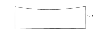
- a semiconductor light receiving element is used as the photodetector 3, but the present invention is not limited to this configuration. It is also possible to employ a configuration using a photodetector configured with a photomultiplier tube as shown in FIG. Since such a photodetector is a vacuum tube, the incident surface on which the fluorescence is incident has a shape recessed by negative pressure.
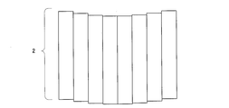
- FIG. 10 illustrates the scintillator 2 according to the second embodiment.
- the relative positions of the scintillator crystals C are adjusted in the height direction so that the bottom surface (outgoing surface) coupled to the photodetector 3 has the same shape as the curve of the incident surface of the photodetector 3. It has a configuration.
- the shape of the surface coupled to the photodetector 3 in the scintillator 2 is the shape of the surface coupled to the scintillator 2 in the photodetector 3.
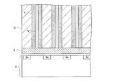
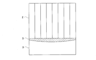
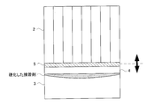
- FIG. 11 shows a state where the scintillator 2 and the photodetector 3 are optically coupled via the adhesive sheet 5. Since the adhesive sheet 5 is deformable, the adhesive sheet 5 that adheres to the scintillator 2 and the photodetector 3 is curved along the curve of the incident surface of the photodetector 3. The scintillator 2 and the light detector 3 are optically coupled with the curved adhesive sheet 5 in close contact with the gap.
- the bottom surface (outgoing surface) of the scintillator 2 has the same shape as the curve of the incident surface of the photodetector 3, but instead of this configuration, as shown in FIG.
- the bottom surface can be flat.
- the pressure-sensitive adhesive sheet 5 has a sufficient thickness. If the pressure-sensitive adhesive sheet 5 has a thickness, the pressure-sensitive adhesive sheet 5 is also deformed in the thickness direction. According to the configuration described in FIG. 12, the thickness is thin at both ends of the pressure-sensitive adhesive sheet 5, and the thickness is thick at the center of the pressure-sensitive adhesive sheet 5.
- the thickness of the pressure-sensitive adhesive sheet 5 partially changes because the pressure-sensitive adhesive sheet 5 is deformed by pressing the scintillator 2 and the photodetector 3 having different surface shapes.
- the scintillator 2 and the photodetector 3 are optically coupled in a state where they are in close contact with the adhesive sheet 5 having a partially different thickness.
- the surface of the adhesive sheet 5 that is adhered to the photodetector 3 is adhered to the photodetector 3 in a state of being deformed to the shape of the surface to which the adhesive sheet 5 of the photodetector 3 is adhered.
- the surface of the adhesive sheet 5 adhered to the scintillator 2 is adhered to the scintillator 2 in a state of being deformed into the shape of the surface of the scintillator 2 to which the adhesive sheet 5 is adhered.
- the scintillator 2 and the photodetector 3 are directly coupled, but as shown in FIG. 13, fluorescence is generated between the scintillator 2 and the photodetector 3. It is good also as a structure provided with the light guide 4 to let it pass.
- the light guide 4 has a configuration in which a transmission material that transmits fluorescence and a reflection plate are combined, and is an assembly of a plurality of parts.
- the light guide 4 is shaped so that the bottom surface (outgoing surface) coupled to the photodetector 3 has the same shape as the curve of the incident surface of the photodetector 3.
- the shape of the surface of the light guide 4 coupled to the photodetector 3 is the shape of the surface of the photodetector 3 to which the light guide 4 is coupled.
- the upper surface (incident surface) coupled to the scintillator 2 of the light guide 4 is the same plane as the exit surface of the scintillator 2.
- the scintillator 2 and the light guide 4 are integrated by a cured adhesive.
- the light guide 4 is optically coupled to the scintillator 2 via an optical adhesive.
- This adhesive is in a liquid state before being cured, and can be injected between the scintillator 2 and the light guide 4. When the adhesive is cured, the scintillator 2 and the light guide 4 are firmly integrated.
- the adhesive sheet 5 is disposed between the light detector 3 and the light guide 4.
- the light guide 4 and the photodetector 3 are optically coupled via the adhesive sheet 5. Thereby, the scintillator 2 and the photodetector 3 are indirectly coupled.
- the pressure-sensitive adhesive strength of the pressure-sensitive adhesive sheet 5 is set to be weaker than the bonding strength of the adhesive that bonds the scintillator 2 and the light guide 4.
- the adhesive sheet 5 detachably couples the combined body of the scintillator 2 and the light guide 4 and the photodetector 3.
- the adhesive strength of the adhesive sheet 5 is set to be smaller than the force necessary to break the light guide 4. Therefore, even if a force is applied to the light guide 4 so as to peel off the scintillator 2 and the photodetector 3, the force applied to the light guide 4 does not yield and collapse.
- the combined body in which the light guide 4 and the scintillator 2 are optically coupled can be reused for manufacturing the radiation detector.
- the bottom surface (outgoing surface) of the light guide 4 has the same shape as the curve of the incident surface of the light detector 3, but instead of this configuration, as shown in FIG.
- the bottom surface of 4 can be flat.
- the pressure-sensitive adhesive sheet 5 has a sufficient thickness.
- the surface of the adhesive sheet 5 that is adhered to the photodetector 3 is adhered to the photodetector 3 in a state of being deformed into the shape of the surface to which the adhesive sheet 5 of the photodetector 3 is adhered.
- the surface of the pressure-sensitive adhesive sheet 5 that is adhered to the light guide 4 is adhered to the light guide 4 in a state of being deformed into the shape of the surface of the light guide 4 to which the pressure-sensitive adhesive sheet 5 is adhered.
- the adhesive sheet 5 is disposed between the light detector 3 and the light guide 4. Therefore, when a force for peeling the adhesive sheet 5 is applied to the radiation detector shown in FIG. 14, the combined body of the scintillator 2 and the light guide 4 and the photodetector 3 are separated as shown by the arrows in FIG. Even if a force is applied to the scintillator 2 so as to peel off the scintillator 2 and the photodetector 3, the scintillator 2 and the light guide 4 are not separated from the scintillator 2 and the light guide 4. .
- the adhesive sheet 5 is disposed between the light detector 3 and the light guide 4. However, as illustrated in FIG. 15, the adhesive sheet 5 is disposed between the light guide 4 and the scintillator 2. You may make it do.
- the photodetector 3 and the light guide 4 are integrated by a cured adhesive, and the light guide 4 is optically coupled to the photodetector 3 through an optical adhesive.
- This adhesive is in a liquid state before being cured, and can be injected between the photodetector 3 and the light guide 4. When the adhesive is cured, the photodetector 3 and the light guide 4 are firmly integrated.
- the adhesive sheet 5 is disposed between the light guide 4 and the scintillator 2.
- the light guide 4 and the scintillator 2 are optically coupled via an adhesive sheet 5. Thereby, the scintillator 2 and the photodetector 3 are indirectly coupled.
- the adhesive sheet 5 detachably couples the scintillator 2, the light guide 4, and the combined optical detector 3. Therefore, if a force for peeling off the adhesive sheet 5 is applied to the radiation detector shown in FIG. 15, the combined body of the photodetector 3 and the light guide 4 and the scintillator 2 are separated as shown by the arrows in FIG. At this time, the light guide 4 is separated from the scintillator 2 while being fixed to the photodetector 3.
- the pressure-sensitive adhesive force of the pressure-sensitive adhesive sheet 5 is set to be weaker than the bonding force of the adhesive that bonds the photodetector 3 and the light guide 4.
- the configuration of the second embodiment is a case where the light guide 4 is provided at a position sandwiched between the scintillator 2 and the photodetector 3, and in particular, between the light guide 4 and the photodetector 3.
- positioned is demonstrated.
- the above-described configuration is set so that the adhesive force of the adhesive sheet 5 is smaller than the force necessary for damaging the light guide 4. If an excessive force is applied to the light guide 4, parts constituting the light guide 4 are physically separated from each other, or the light guide 4 is cracked.
- the adhesive sheet 5 peels off from the photodetector 3 before the light guide 4 collapses. To separate. Therefore, according to the configuration of the present invention, the intact light guide 4 separated from the photodetector 3 can be reused.
- the shape of the surface coupled to the scintillator 2 in the photodetector 3 may not be a flat surface. Therefore, for example, if the shape of the surface of the light guide 4 coupled to the light detector 3 is the shape of the surface of the light detector 3 to which the light guide 4 is coupled, the two members are securely in contact with each other. Combined. Moreover, if the adhesive sheet 5 adheres to both members in a state of being deformed so as to absorb the difference in shape between the two members, both members are securely bonded together.
- the present invention is not limited to the configuration of the above-described embodiment, and can be modified as follows.
- the photodetector 3 having the semiconductor light receiving element 3a and the scintillator 2 are integrated through the adhesive sheet 5, but as shown in FIG. 16, the scintillator 2, the photodetector 3 and It is good also as a structure provided with the light guide 4 between.
- the scintillator 2 and the light guide 4 are integrated with an adhesive, and the adhesive sheet 5 is positioned between the light guide 4 and the photodetector 3.
- the photodetector 3 and the light guide 4 may be integrated with an adhesive, and the adhesive sheet 5 may be positioned between the light guide 4 and the scintillator 2.
- the radiation detector of the present invention can be mounted on a medical radiation imaging apparatus such as a PET (Positron Emission Tomography) apparatus.
- a medical radiation imaging apparatus such as a PET (Positron Emission Tomography) apparatus.
- the present invention is suitable for the medical field.
Landscapes
- Physics & Mathematics (AREA)
- Health & Medical Sciences (AREA)
- Spectroscopy & Molecular Physics (AREA)
- Molecular Biology (AREA)
- Life Sciences & Earth Sciences (AREA)
- General Physics & Mathematics (AREA)
- High Energy & Nuclear Physics (AREA)
- Engineering & Computer Science (AREA)
- Chemical & Material Sciences (AREA)
- Crystallography & Structural Chemistry (AREA)
- Biomedical Technology (AREA)
- General Health & Medical Sciences (AREA)
- Medical Informatics (AREA)
- Nuclear Medicine, Radiotherapy & Molecular Imaging (AREA)
- Optics & Photonics (AREA)
- Measurement Of Radiation (AREA)
- Nuclear Medicine (AREA)
Abstract
L'invention concerne un détecteur de rayonnement ayant une structure qui peut être désassemblée pour faciliter l'entretien. Dans ce détecteur de rayonnement (1), un scintillateur (2) et un photodétecteur (3) sont connectés séparément et optiquement par une feuille adhésive (5). Par conséquent, si une force est appliquée sur le détecteur de rayonnement (1) de manière à séparer le scintillateur (2) et le photodétecteur (3) l'un de l'autre, la feuille adhésive (5) se décolle et ne fonctionne plus de façon à intégrer le scintillateur (2) et le photodétecteur (3). Dans ce détecteur de rayonnement (1), le scintillateur (2) et le photodétecteur (3) peuvent ainsi être séparés physiquement.
Applications Claiming Priority (2)
| Application Number | Priority Date | Filing Date | Title |
|---|---|---|---|
| JP2015-099210 | 2015-05-14 | ||
| JP2015099210A JP2018109517A (ja) | 2015-05-14 | 2015-05-14 | 放射線検出器およびそれを備えた放射線断層撮影装置 |
Publications (1)
| Publication Number | Publication Date |
|---|---|
| WO2016181708A1 true WO2016181708A1 (fr) | 2016-11-17 |
Family
ID=57248202
Family Applications (1)
| Application Number | Title | Priority Date | Filing Date |
|---|---|---|---|
| PCT/JP2016/058851 Ceased WO2016181708A1 (fr) | 2015-05-14 | 2016-03-18 | Détecteur de rayonnement, et dispositif de tomographie par rayonnement le comprenant |
Country Status (2)
| Country | Link |
|---|---|
| JP (1) | JP2018109517A (fr) |
| WO (1) | WO2016181708A1 (fr) |
Cited By (1)
| Publication number | Priority date | Publication date | Assignee | Title |
|---|---|---|---|---|
| CN114447146A (zh) * | 2021-12-27 | 2022-05-06 | 江苏赛诺格兰医疗科技有限公司 | 一种sipm探测器的返修方法 |
Families Citing this family (1)
| Publication number | Priority date | Publication date | Assignee | Title |
|---|---|---|---|---|
| JP7584141B2 (ja) * | 2021-03-24 | 2024-11-15 | 国立研究開発法人量子科学技術研究開発機構 | 放射線検出器、シンチレータユニット、画像生成装置、及びシンチレータユニットの製造方法 |
Citations (6)
| Publication number | Priority date | Publication date | Assignee | Title |
|---|---|---|---|---|
| JPH04303786A (ja) * | 1991-03-31 | 1992-10-27 | Shimadzu Corp | 放射線検出器 |
| JP2002006050A (ja) * | 2000-06-26 | 2002-01-09 | Canon Inc | 二次元撮像装置の実装構造 |
| JP2003240857A (ja) * | 2002-02-19 | 2003-08-27 | Shimadzu Corp | 放射線検出器 |
| JP2004061492A (ja) * | 2002-06-04 | 2004-02-26 | Hitachi Medical Corp | X線検出器用シンチレータ、その製造方法並びにそれを用いたx線検出器及びx線ct装置 |
| JP2005274526A (ja) * | 2004-03-26 | 2005-10-06 | Shimadzu Corp | 放射線検出器およびその製造方法 |
| JP2012108048A (ja) * | 2010-11-18 | 2012-06-07 | Fujifilm Corp | 放射線検出器および放射線画像撮影装置 |
-
2015
- 2015-05-14 JP JP2015099210A patent/JP2018109517A/ja active Pending
-
2016
- 2016-03-18 WO PCT/JP2016/058851 patent/WO2016181708A1/fr not_active Ceased
Patent Citations (6)
| Publication number | Priority date | Publication date | Assignee | Title |
|---|---|---|---|---|
| JPH04303786A (ja) * | 1991-03-31 | 1992-10-27 | Shimadzu Corp | 放射線検出器 |
| JP2002006050A (ja) * | 2000-06-26 | 2002-01-09 | Canon Inc | 二次元撮像装置の実装構造 |
| JP2003240857A (ja) * | 2002-02-19 | 2003-08-27 | Shimadzu Corp | 放射線検出器 |
| JP2004061492A (ja) * | 2002-06-04 | 2004-02-26 | Hitachi Medical Corp | X線検出器用シンチレータ、その製造方法並びにそれを用いたx線検出器及びx線ct装置 |
| JP2005274526A (ja) * | 2004-03-26 | 2005-10-06 | Shimadzu Corp | 放射線検出器およびその製造方法 |
| JP2012108048A (ja) * | 2010-11-18 | 2012-06-07 | Fujifilm Corp | 放射線検出器および放射線画像撮影装置 |
Cited By (2)
| Publication number | Priority date | Publication date | Assignee | Title |
|---|---|---|---|---|
| CN114447146A (zh) * | 2021-12-27 | 2022-05-06 | 江苏赛诺格兰医疗科技有限公司 | 一种sipm探测器的返修方法 |
| CN114447146B (zh) * | 2021-12-27 | 2023-05-26 | 江苏赛诺格兰医疗科技有限公司 | 一种sipm探测器的返修方法 |
Also Published As
| Publication number | Publication date |
|---|---|
| JP2018109517A (ja) | 2018-07-12 |
Similar Documents
| Publication | Publication Date | Title |
|---|---|---|
| US8779364B2 (en) | Scintillator panel, radiation detection apparatus, and method of manufacturing them | |
| CN103185914B (zh) | 用于辐射检测器的光导组件 | |
| CN105278138B (zh) | 液晶显示装置 | |
| CN102506362A (zh) | 背光模组 | |
| CN109324341B (zh) | 放射线检测装置及其制造方法和放射线成像系统 | |
| CN108307636A (zh) | 表面保护膜 | |
| KR20190009863A (ko) | 표시 장치 및 그 제조 방법 | |
| WO2016181708A1 (fr) | Détecteur de rayonnement, et dispositif de tomographie par rayonnement le comprenant | |
| CN109239761B (zh) | 辐射检测装置、辐射检测系统、以及用于制造辐射检测装置的方法 | |
| KR102155252B1 (ko) | 유기 발광 표시 장치 및 유기 발광 표시 장치 제조 방법 | |
| US10684409B2 (en) | Backlight module and liquid crystal display device | |
| JP6669168B2 (ja) | 放射線検出器またはそれを備えた放射線断層撮影装置 | |
| US20160172414A1 (en) | Radiation imaging apparatus, method of manufacturing the same, and radiation inspection apparatus | |
| CN106292034B (zh) | 一种液晶显示装置 | |
| CN103456896B (zh) | 显示装置 | |
| JP2015049121A5 (fr) | ||
| CN216848224U (zh) | 一种偏光片和显示装置 | |
| CN214705247U (zh) | 柔性屏组件 | |
| EP3172453B1 (fr) | Procédé de collage avec durcissement par des rayons actiniques réfléchis | |
| JP2015049123A5 (fr) | ||
| WO2009128135A1 (fr) | Procédé de fabrication d’un guide de lumière et procédé de fabrication d’un détecteur de rayonnement | |
| JP5272300B2 (ja) | 固体撮像素子の製造方法 | |
| JP6845631B2 (ja) | 表示装置の組立方法 | |
| CN109868071A (zh) | 贴合胶膜及其制造方法 | |
| CN103149716A (zh) | 一种显示装置及其组装方法 |
Legal Events
| Date | Code | Title | Description |
|---|---|---|---|
| 121 | Ep: the epo has been informed by wipo that ep was designated in this application |
Ref document number: 16792433 Country of ref document: EP Kind code of ref document: A1 |
|
| NENP | Non-entry into the national phase |
Ref country code: DE |
|
| 122 | Ep: pct application non-entry in european phase |
Ref document number: 16792433 Country of ref document: EP Kind code of ref document: A1 |
|
| NENP | Non-entry into the national phase |
Ref country code: JP |