WO2016181720A1 - Dispositif endoscopique et procédé de commande de dispositif endoscopique - Google Patents
Dispositif endoscopique et procédé de commande de dispositif endoscopique Download PDFInfo
- Publication number
- WO2016181720A1 WO2016181720A1 PCT/JP2016/060671 JP2016060671W WO2016181720A1 WO 2016181720 A1 WO2016181720 A1 WO 2016181720A1 JP 2016060671 W JP2016060671 W JP 2016060671W WO 2016181720 A1 WO2016181720 A1 WO 2016181720A1
- Authority
- WO
- WIPO (PCT)
- Prior art keywords
- transmission amount
- polarizing plate
- subject
- relative angle
- linearly polarizing
- Prior art date
- Legal status (The legal status is an assumption and is not a legal conclusion. Google has not performed a legal analysis and makes no representation as to the accuracy of the status listed.)
- Ceased
Links
Images


Classifications
-
- A—HUMAN NECESSITIES
- A61—MEDICAL OR VETERINARY SCIENCE; HYGIENE
- A61B—DIAGNOSIS; SURGERY; IDENTIFICATION
- A61B1/00—Instruments for performing medical examinations of the interior of cavities or tubes of the body by visual or photographical inspection, e.g. endoscopes; Illuminating arrangements therefor
-
- G—PHYSICS
- G02—OPTICS
- G02B—OPTICAL ELEMENTS, SYSTEMS OR APPARATUS
- G02B23/00—Telescopes, e.g. binoculars; Periscopes; Instruments for viewing the inside of hollow bodies; Viewfinders; Optical aiming or sighting devices
- G02B23/24—Instruments or systems for viewing the inside of hollow bodies, e.g. fibrescopes
- G02B23/26—Instruments or systems for viewing the inside of hollow bodies, e.g. fibrescopes using light guides
Definitions
- the present disclosure relates to an endoscope apparatus and a control method of the endoscope apparatus.
- first illumination light which is illumination light from a first light source
- first polarizing plate is polarized by a first polarizing plate and hits an object. From image light from the object, first polarization A configuration is described in which surface reflected light is blocked when passing through a plate and a polarizing plate whose polarization direction is orthogonal.
- the non-reflective image without the surface reflection wave (specular reflection component) to be acquired has a different texture and impression of the subject from a normal image having a specular reflection component, It is difficult to use for normal observation. For this reason, a complicated process of selectively using a normal image (reflected image) and a non-reflective image according to the purpose of observation is required. Further, the technique described in the above publication has a problem in that the imaging frame rate is reduced because a normal image and a non-reflective image are alternately obtained.
- the irradiation unit that emits linearly polarized light and irradiates the subject, and the first linear polarizing plate that transmits the light incident from the subject and enters the imaging device, the first from the subject is provided.
- an endoscope apparatus in which the relative angle between the direction of linearly polarized light incident on the linearly polarizing plate and the polarization axis of the first linearly polarizing plate can be changed.
- the linearly polarized light is emitted to irradiate the subject, the amount of transmission of the first linearly polarizing plate that transmits the light incident from the subject and enters the imaging device, and Controlling the relative angle between the direction of linearly polarized light incident on the first linearly polarizing plate from the subject and the polarization axis of the first linearly polarizing plate based on the estimated transmission amount,
- a method for controlling an endoscopic device is provided.
- FIG. 7 S12 It is a schematic diagram which shows a mode that non-polarized light turns into linearly polarized light by permeate
- FIG. 1 a schematic configuration of a system according to an embodiment of the present disclosure will be described with reference to FIG.
- an endoscopic surgery system 10 disposed in an operating room as shown in FIG. 1 is used.
- several opening devices called trocars 12a and 12b are attached to the abdominal wall, and the laparoscope (hereinafter referred to as the internal (Also referred to as an endoscope) 2, the energy treatment tool 3, the forceps 4 and the like are inserted into the body.
- the laparoscope hereinafter referred to as the internal (Also referred to as an endoscope) 2
- the energy treatment tool 3 the forceps 4 and the like
- a treatment such as excision of the affected part 16 with the energy treatment tool 3 or the like is performed while viewing the image of the affected part (tumor or the like) 16 captured by the endoscope 2 in real time.
- the endoscope 2, the energy treatment tool 3, and the forceps 4 are held by an operator, an assistant, a scopist, a robot, or the like.
- a rigid endoscope is exemplified as the endoscope 2, but the endoscope 2 may be a flexible endoscope.
- a cart 14 equipped with devices for endoscopic operation, a patient bed 13 on which a patient lies, a foot switch 15 and the like are arranged.
- the cart 14 is equipped with devices such as a camera control unit (CCU) 5, a light source device 6, a treatment instrument device 7, a pneumoperitoneum device 8, a display device 9, a recorder 10, and a printer 11 as medical devices.
- CCU camera control unit
- An image image signal of the affected area 16 imaged through the observation optical system of the endoscope 2 is transmitted to the CCU 5 via the camera cable, processed in the CCU 5, and then output to the display device 9. A mirror image is displayed.
- the CCU 5 may be connected wirelessly.
- the light source device 6 is connected to the endoscope 2 via a light guide cable, and can switch and irradiate the affected part 16 with light of various wavelengths.
- the treatment instrument device 7 is a high-frequency output device that outputs a high-frequency current to the energy treatment instrument 3 that cuts the affected part 16 using electric heat.
- the pneumoperitoneum device 8 is provided with air supply and intake means, and supplies air to, for example, the abdominal region in the patient's body.
- the foot switch 15 controls the CCU 5, the treatment instrument device 7 and the like by using a foot operation of an operator or an assistant as a trigger signal.
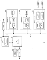
- FIG. 2 is an explanatory diagram showing an example of the hardware configuration of the CCU 5 in FIG.
- the CCU 5 includes, for example, an FPGA board 21, a CPU 22, GPU boards 231 and 232, a memory 24, an IO controller 25, a recording medium 26, and an interface 27. Further, the FPGA board 21, the CPU 22, and the GPU boards 231 and 232 are connected by a bus 28, for example.
- the FPGA board 21 includes, for example, an FPGA (Field Programmable Gate Array), an input interface (input IF) to which an input image signal is input from the endoscope 2 in FIG. 1, and an output image signal to the display device 9 in FIG. An output interface (output IF) for output is included. An input image signal is input to the input interface (input IF) from an image sensor provided in the endoscope 2.
- FPGA Field Programmable Gate Array
- the CPU 22 and the GPU boards 231 and 232 perform various processes by executing various software such as related software.
- the CPU 22 includes a processor.
- Each of the GPU boards 231 and 232 includes a GPU (Graphics Processing Unit) and a DRAM (Dynamic Random Access Memory).
- the memory 24 stores various data such as data corresponding to the input image signal from the endoscope 2 and data corresponding to the output image signal to the display device 9.
- the CPU 22 serves to control writing and reading of various data to the memory 24.
- the CPU 22 divides the image data stored in the memory 24 according to the data stored in the memory 24, the processing capabilities of the GPU boards 231 and 232, and the processing content. Then, the GPUs of the GPU boards 231 and 232 perform predetermined processing on the divided and supplied data, and output the processing result to the CPU 22.
- the IO controller 25 serves to control transmission of signals between the CPU 22, the recording medium 26 and the interface 27, for example.
- the recording medium 26 functions as a storage unit (not shown) and stores various data such as image data and various applications.
- examples of the recording medium 26 include a solid state drive.
- the recording medium 26 may be detachable from the CCU 5.
- Examples of the interface 27 include a USB (Universal Serial Bus) terminal and processing circuit, a LAN (Local Area Network) terminal, and a transmission / reception circuit.
- USB Universal Serial Bus
- LAN Local Area Network
- FIG. 2 shows an example in which there are two GPU boards 231 and 232, but the number may be two or more. Further, when the CPU 22 has a GPU function, the CCU 5 may not include the GPU boards 231 and 232.
- FIG. 3 is a schematic diagram illustrating a configuration of a distal end portion of a general endoscope 2.
- the light guided from the illumination unit (light source device 6) is emitted from the illumination window 2a.
- incident light from the subject enters through the observation window 2b and is guided to the imaging unit (image sensor). Since the illuminating unit and the imaging unit are arranged in parallel, the optical axes of the illuminating unit and the imaging unit are substantially equal, and the light incident on the imaging unit is likely to include a specular reflection component.
- the specular reflection component that reflects immediately on the object surface is very strong compared to the diffuse reflection component that is reflected in an object in a complex direction by reflecting inside the object, which is the subject, and causes glare when entering the field of view. In addition to being a cause of stress, it does not have color information on the surface of the object, which is harmful to observation.
- FIG. 4 is a schematic diagram for explaining the principle of removing the specular reflection component by installing linearly polarizing plates 50 and 52 whose optical axes are orthogonal to each other in the illumination unit and the imaging unit.
- the non-polarized light beam 60 guided by the light guide cable reaches and is absorbed by the linearly polarizing plate 50 installed on the illumination side, and a part thereof is parallel to the optical axis (polarizing axis) of the linearly polarizing plate 50. It is transmitted through the linear polarizer 50 as linearly polarized light in the polarization direction.
- This linearly polarized light is applied to an object which is a subject, and is reflected by being separated into a diffuse reflection component and a specular reflection component.
- the two reflection components reach the linear polarizing plate 52 having an optical axis orthogonal to the linear polarizing plate 50 installed on the imaging unit side (sensor side), and the specular reflection component that is a linearly polarized light that maintains the polarization state is a straight line.
- a part of the diffuse reflection component that has been absorbed by the polarizing plate 52 and canceled the polarization state is transmitted as linearly polarized light having a polarization direction parallel to the optical axis of the linearly polarizing plate 52 and is incident on the imaging unit.
- the specular reflection component is an important clue about the appearance of an object such as a three-dimensional feeling and texture when a person recognizes an object
- an image from which the specular reflection component is completely removed is an ordinary image having a specular reflection component. Has the problem of giving viewers a different impression.
- an endoscope having a specular reflection removal function using a conventional polarizing plate must be switched between imaging with specular reflection and imaging without specular reflection according to the purpose of observation, and is complicated. Was requested.
- the linear polarizing plate 50 is rotated about the optical axis, and the relative angle of the optical axis of the linear polarizing plate 52 is less than 90 ° with respect to the polarization direction of the linearly polarized light irradiated to the subject. Can be realized.
- the relative angle of the optical axis of the linearly polarizing plate 52 is less than 90 ° with respect to the polarization direction of the linearly polarized light irradiated to the subject. can do.
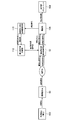
- FIG. 5 is a block diagram showing a configuration of the system 100 of the present embodiment.
- the system 100 is basically configured in the endoscope 2 except for the display unit 108.
- this system includes a light source device 102 (corresponding to the light source device 6 in FIG. 1), a linearly polarizing plate 52, an imaging unit (imaging device) 106, a display unit 108, and a specular reflection component transmission amount estimation unit 110. , And a polarizing plate angle control unit 112.
- the linear polarizing plate 52 is configured to be rotatable about the optical axis.
- the display unit 108 corresponds to the display device 9 of FIG.
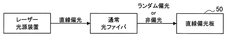
- FIG. 6 is a schematic diagram illustrating a configuration example for irradiating linearly polarized light.
- the luminous flux irradiated to the subject can be kept in the polarization state by guiding the linearly polarized light irradiated from the laser light source device (the light source device 102 in FIG. 5) through the polarization preserving optical fiber. good.
- the laser light source device or the polarization maintaining optical fiber corresponds to an irradiation unit that emits linearly polarized light and irradiates the subject. Further, as shown in FIG.
- the linearly polarized light 50 shown in FIG. 4 is obtained from the light that is randomly polarized or non-polarized by guiding the linearly polarized light emitted from the laser light source device through a normal optical fiber. May be used to extract linearly polarized light.
- the linearly polarizing plate 50 corresponds to an irradiation unit that emits linearly polarized light and irradiates the subject.
- FIG. 7 is a schematic diagram showing how non-polarized light becomes linearly polarized light by passing through the linearly polarizing plates 50 and 52.
- FIG. 8 shows an example in which light irradiated from the non-polarized light source device 103 is transmitted through the linearly polarizing plate 50 and linearly polarized light is extracted.
- the other structure of FIG. 8 is the same as that of FIG. Also in this case, the linearly polarizing plate 50 corresponds to an irradiation unit that emits linearly polarized light and irradiates the subject.
- the linearly polarized irradiation light applied to the subject is reflected by the non-polarized diffuse reflection component that is complicatedly reflected inside the subject and the polarization state is eliminated, and is immediately reflected on the surface and maintains the polarization state of the irradiation light. It is divided into a specular reflection component and reflected.
- the linearly polarizing plate 52 has an optical axis that is neither parallel nor orthogonal to the polarization direction of the linearly polarized light irradiated to the subject (the polarization direction of the specular reflection component).
- the two types of reflected light components pass through the linearly polarizing plate 52 and are attenuated according to the relative angle between the linearly polarizing plate 52 and the polarization direction of the specularly reflected component, and according to the transmission amount of the linearly polarizing plate 52.
- the diffuse reflection component attenuated in this way enters the imaging unit 106 (image sensor), and imaging is performed.
- the specular reflection component transmission amount estimation unit 110 estimates an appropriate transmission amount P of the specular reflection component from the luminance signal of the captured image.
- the saturation region of the luminance signal is used as the specular reflection component.
- the intensity difference between the specular reflection component and the diffuse reflection component is used. Since the intensity of the reflected light is extremely high in the region including the specular reflection component, when the subject is photographed with an appropriate exposure, the specular reflection does not fall within the range of the range that can be imaged by the imaging unit 106, and usually the luminance signal does not exist. Saturates. Therefore, the ratio of the specular reflection component is derived by converting the ratio of the saturated region of the captured image signal and the number of isolated points as the ratio of the specular reflection component.
- the polarizing plate angle control unit 112 changes the relative angle between the linearly polarized light irradiated to the subject and the linearly polarizing plate 52 based on the transmission amount of the specularly reflected component through the linearly polarizing plate 52, and the intensity of the specularly reflected component is optimal. Make adjustments.
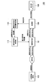
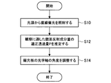
- FIG. 9 is a flowchart showing the basic processing of this embodiment.
- the light source device 102 irradiates the subject with linearly polarized light.
- an appropriate transmission amount P of the specular reflection component amount suitable for observation is estimated.
- the angle of the optical axis of the linearly polarizing plate 52 is adjusted.
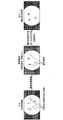
- FIG. 10 and 11 are schematic diagrams illustrating a method for estimating the proper transmission amount P.
- the specular reflection component is suppressed or the specular reflection component is promoted (accelerated) according to the appropriate transmission amount P.
- FIG. 10 shows a case where the specular reflection component is suppressed
- FIG. 11 shows a case where the specular reflection component is promoted.
- the input image obtained by imaging by the imaging unit 106 is a highly reflective image including a specular reflection component, and has a region where the intensity of reflected light is high.
- a luminance image obtained by converting a high-reflectance image, which is an input image, into a luminance image is sent to the specular reflection component transmission amount estimation unit 110. That is, the luminance signal of each pixel is sent to the specular reflection component transmission amount estimation unit 110.
- the luminance image has a saturation region of the luminance signal.
- the saturation region corresponds to a region where the intensity of reflected light is high.
- the proper transmission amount P is calculated based on the area of the saturation region.
- the proper transmission amount P may be derived from the ratio of the area of the saturated region to the area of the entire image (area of the visual field (inside the circle) shown in FIGS. 10 and 11).
- the appropriate transmission amount P may be obtained for each imaging frame, or may be obtained at regular time intervals.
- the intensity of the reflected light is determined based on the area of the saturated region, and the angle of the linearly polarizing plate 52 is changed according to the intensity of the reflected light.
- the area of the saturated region is equal to or larger than the threshold value, it is determined that the intensity of the reflected light is high, and the incidence of the specular reflection component on the imaging device 106 is suppressed.
- the relative angle between the direction of the linearly polarized light of the irradiation light applied to the subject and the optical axis of the linearly polarizing plate 52 is brought close to 90 °. Thereby, a specular reflection component is suppressed and an image of appropriate reflection can be output.
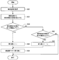
- FIG. 12 is a flowchart showing in detail the process of step S12 of FIG.
- step S20 a luminance image is acquired.
- step S22 the area of the saturation region is detected from the luminance image.
- step S24 it is determined whether or not the area of the saturated region is equal to or smaller than the first threshold value. If the area of the saturated region is equal to or smaller than the threshold value, the process proceeds to step S26.
- step S26 the change amount ⁇ of the appropriate transmission amount P is set to a predetermined amount n (n is a positive value) in order to promote specular reflection.
- step S28 the change amount ⁇ is added to the previously determined appropriate transmission amount P. As a result, the current proper transmission amount P increases, and specular reflection is promoted. After step S28, the process ends.
- step S30 it is determined whether or not the area of the saturated region is equal to or larger than the second threshold value. -N is a negative value).
- step S28 the change amount ⁇ is added to the previous proper transmission amount P. As a result, the current proper transmission amount P is reduced, and specular reflection is suppressed.
- the magnitude relationship between the first threshold value and the second threshold value is first threshold value ⁇ second threshold value.
- first threshold value ⁇ second threshold value.
- the area of the saturated region is less than the second threshold value in step S30, the area of the saturated region is larger than the first threshold value and the area of the saturated region is less than the second threshold value.
- the transmission amount is determined to be the same as the previous appropriate transmission amount P, and the process is terminated.
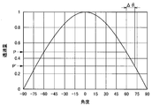
- FIG. 13 is a characteristic diagram showing the relationship between the transmission amount of the specular reflection component in the linearly polarizing plate 52 and the relative angle ⁇ . According to FIG. 13, the relative angle ⁇ can be calculated based on the appropriate transmission amount P.
- the amount of transmission on the vertical axis is a value obtained by normalizing the single transmittance of the polarizing plate by 1.0.
- the transmission amount at a relative angle of 0 ° is 1.0
- the transmission amount is 1 ⁇ 2 at a relative angle of 60.0 °.
- the transmission amount is about 1/5 at a relative angle of 78.5 °.
- the transmission amount is about 1/10 at a relative angle of 84.3 °.
- the transmission amount is about 1/20 at a relative angle of 87.1 °.
- the relative angle ⁇ can be uniquely determined according to the appropriate transmission amount P.
- FIG. 14 is a schematic diagram showing the transmittance when light rays pass through the linear polarizing plate 52.
- Non-polarized light passes through the linearly polarizing plate 52 with a predetermined transmittance (here, 30%).
- the linearly polarized light is transmitted through the linearly polarizing plate 52 depending on the relative angle ⁇ .
- FIG. 14 shows a state where linearly polarized light is transmitted with a transmittance of 60% according to the relative angle ⁇ .
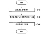
- FIG. 15 is a flowchart showing processing for adjusting the relative angle ⁇ .
- step S40 an appropriate transmission amount P is acquired.
- step S42 the relative angle ⁇ is acquired from the appropriate transmission amount P based on FIG.
- step S44 based on the relative angle ⁇ acquired in step S42, the relative angle ⁇ between the direction of the linearly polarized light of the irradiation light irradiated on the subject and the optical axis of the linearly polarizing plate 52 is adjusted.
- the adjustment of the relative angle ⁇ may be performed for each imaging frame similarly to the acquisition of the appropriate transmission amount P, or may be adjusted at regular time intervals.
- FIG. 16 is a flowchart showing another process for adjusting the relative angle.
- the previous proper transmission amount P is stored, and the relative angle ⁇ is corrected when the difference between the previous proper transmission amount P and the present proper transmission amount P ′ exceeds a threshold value.
- step S50 the current proper transmission amount P 'and the previous proper transmission amount P are acquired.
- step S52 it is determined whether or not
- step S54 the change amount ⁇ of the relative angle ⁇ is calculated from P′-P.
- the relative angle change amount ⁇ can be obtained from the characteristics shown in FIG.
- the previous relative angle ⁇ is changed based on the change amount ⁇ .
- the specular reflection component can be increased by bringing the relative angle ⁇ closer to 0 ° by ⁇ from the previous relative angle ⁇ . it can.
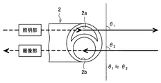
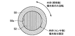
- FIGS. 17, 18A, and 18B are schematic views showing the distal end portion of the endoscope 2.
- the linear polarizing plate 50 can be rotated, and the linear polarizing plate 52 is fixed, so that the relative angle ⁇ is set.
- FIG. 17 is a schematic diagram showing a cross section along the optical axis of the endoscope 2
- FIGS. 18A and 18B are schematic diagrams showing a state in which the distal end portion of the endoscope 2 is viewed from the front in the optical axis direction.
- FIG. The configuration examples shown in FIGS. 17, 18A, and 18B are examples in which the linearly polarizing plate 50 and the linearly polarizing plate 52 are provided, and correspond to the configuration of FIG.
- the illumination light guided from the light source device 103 passes through the linearly polarizing plate 50 configured in a ring shape and is irradiated to the subject.
- Incident light from the subject passes through the central hole 50 a of the ring-shaped linearly polarizing plate 50, passes through the linearly polarizing plate 52 provided on the front surface of the imaging unit 106, and enters the imaging unit 106.
- a cover member 56 is provided on the front surface of the linear polarizing plate 50.
- 18A shows a state where the cover member 56 at the distal end portion of the endoscope 2 is removed
- FIG. 18B shows a case where the cover member 56 is attached.
- the linearly polarizing plate 50 has a ring shape
- the cover member 56 is provided with an illumination window 56a.
- the illumination light guided from the light source device 103 passes through the linearly polarizing plate 50 configured in a ring shape, and is irradiated to the subject from the illumination window 56a.
- the relative angle ⁇ between the direction of the linearly polarized light of the irradiation light applied to the subject and the optical axis of the linearly polarizing plate 52 can also be changed by fixing the linearly polarizing plate 50 and rotating the linearly polarizing plate 52. Can do.
- the present embodiment it is possible to greatly improve the shape / color information of the subject surface whose visibility is reduced by the specular reflection component by reducing the reflection generated on the subject surface.
- the extreme gradation difference between the bright spot and the subject can be alleviated, and stress during viewing can be reduced.
- the specular reflection component can be adjusted optimally, it is not necessary to switch the output image, thereby reducing the burden of endoscope operation.
- the time required for surgery and observation can be shortened. Therefore, by optimally adjusting the specular reflection component, it is possible to improve the visibility of the subject surface that is obstructed by the specular reflection component while maintaining the original texture of the subject created by the specular reflection component.
- An irradiation unit that emits linearly polarized light and irradiates the subject
- a first linearly polarizing plate that transmits light incident from a subject and enters the image sensor
- An endoscope apparatus in which a relative angle between a direction of linearly polarized light incident on the first linearly polarizing plate from a subject and a polarization axis of the first linearly polarizing plate can be changed.
- the irradiation unit includes a second linearly polarizing plate that emits light emitted from the light source unit as linearly polarized light,
- the endoscope apparatus according to (1) wherein a relative angle between a polarization axis of the first linear polarizing plate and a polarization axis of the second linear polarizing plate can be changed.
- a transmission amount estimation unit that estimates a transmission amount of the first linearly polarizing plate;
- An angle control unit for controlling the relative angle based on the transmission amount;
- the transmission amount estimating unit estimates the transmission amount based on an area of a saturated region where a luminance signal is saturated based on image information acquired by the imaging device. Endoscope device.
Landscapes
- Physics & Mathematics (AREA)
- Health & Medical Sciences (AREA)
- Life Sciences & Earth Sciences (AREA)
- Surgery (AREA)
- Optics & Photonics (AREA)
- Biomedical Technology (AREA)
- Medical Informatics (AREA)
- Nuclear Medicine, Radiotherapy & Molecular Imaging (AREA)
- Pathology (AREA)
- Radiology & Medical Imaging (AREA)
- Astronomy & Astrophysics (AREA)
- Engineering & Computer Science (AREA)
- General Physics & Mathematics (AREA)
- Biophysics (AREA)
- Molecular Biology (AREA)
- Heart & Thoracic Surgery (AREA)
- Animal Behavior & Ethology (AREA)
- General Health & Medical Sciences (AREA)
- Public Health (AREA)
- Veterinary Medicine (AREA)
- Endoscopes (AREA)
- Instruments For Viewing The Inside Of Hollow Bodies (AREA)
Abstract
Le problème de l'invention concerne l'obtention d'une image optimale pour l'observation à l'aide d'un élément de réflexion spéculaire. La solution de l'invention porte sur un dispositif endoscopique, pourvu : d'une unité d'irradiation qui émet et projette une lumière polarisée linéairement sur un sujet ; et d'un premier polariseur linéaire qui permet le passage d'un faisceau de lumière incident provenant du sujet à travers celui-ci et son entrée dans un élément d'imagerie. L'angle relatif entre la direction de la lumière linéairement polarisée incidente sur le premier polariseur linéaire provenant du sujet et l'axe de polarisation du premier polariseur linéaire peut être modifié. Par conséquent, la quantité d'un élément de réflexion spéculaire transmise à travers le premier polariseur linéaire peut être régulée de manière optimale et une image optimale pour l'observation à l'aide de l'élément de réflexion spéculaire peut être obtenue.
Applications Claiming Priority (2)
| Application Number | Priority Date | Filing Date | Title |
|---|---|---|---|
| JP2015098500A JP2016209466A (ja) | 2015-05-13 | 2015-05-13 | 内視鏡装置及び内視鏡装置の制御方法 |
| JP2015-098500 | 2015-05-13 |
Publications (1)
| Publication Number | Publication Date |
|---|---|
| WO2016181720A1 true WO2016181720A1 (fr) | 2016-11-17 |
Family
ID=57248169
Family Applications (1)
| Application Number | Title | Priority Date | Filing Date |
|---|---|---|---|
| PCT/JP2016/060671 Ceased WO2016181720A1 (fr) | 2015-05-13 | 2016-03-31 | Dispositif endoscopique et procédé de commande de dispositif endoscopique |
Country Status (2)
| Country | Link |
|---|---|
| JP (1) | JP2016209466A (fr) |
| WO (1) | WO2016181720A1 (fr) |
Cited By (7)
| Publication number | Priority date | Publication date | Assignee | Title |
|---|---|---|---|---|
| WO2018105062A1 (fr) * | 2016-12-07 | 2018-06-14 | オリンパス株式会社 | Dispositif de traitement d'image et procédé de traitement d'image |
| US10972675B2 (en) | 2017-06-12 | 2021-04-06 | Olympus Corporation | Endoscope system |
| US11045081B2 (en) | 2017-06-12 | 2021-06-29 | Olympus Corporation | Endoscope system |
| US11070739B2 (en) | 2017-06-12 | 2021-07-20 | Olympus Corporation | Endoscope system having a first light source for imaging a subject at different depths and a second light source having a wide band visible band |
| US11324385B2 (en) | 2017-06-12 | 2022-05-10 | Olympus Corporation | Endoscope system for processing second illumination image using image information other than image information about outermost surface side of subject among three image information from at least four images of first illumination images |
| US11805988B2 (en) | 2018-06-05 | 2023-11-07 | Olympus Corporation | Endoscope system |
| US11871906B2 (en) | 2018-06-05 | 2024-01-16 | Olympus Corporation | Endoscope system |
Families Citing this family (2)
| Publication number | Priority date | Publication date | Assignee | Title |
|---|---|---|---|---|
| JP7200939B2 (ja) * | 2017-07-19 | 2023-01-10 | ソニーグループ株式会社 | 手術システム、制御方法、手術機器、並びにプログラム |
| US20200187766A1 (en) * | 2018-12-17 | 2020-06-18 | Z Square Ltd | Enhanced multicore fiber endoscopes |
Citations (6)
| Publication number | Priority date | Publication date | Assignee | Title |
|---|---|---|---|---|
| JPS6076716A (ja) * | 1983-10-03 | 1985-05-01 | Olympus Optical Co Ltd | 内視鏡 |
| JPS6076714A (ja) * | 1983-10-03 | 1985-05-01 | Olympus Optical Co Ltd | 偏光フイルタを用いた内視鏡 |
| JPS60111216A (ja) * | 1983-11-18 | 1985-06-17 | Olympus Optical Co Ltd | 入射光量制御手段を備えた内視鏡装置 |
| JPS60111217A (ja) * | 1983-11-18 | 1985-06-17 | Olympus Optical Co Ltd | 入射光量制御手段を備えた内視鏡装置 |
| JPH04104214A (ja) * | 1990-08-24 | 1992-04-06 | Olympus Optical Co Ltd | 観察装置 |
| JP2005000631A (ja) * | 2002-07-03 | 2005-01-06 | Shiyoufuu:Kk | 歯科口腔測色写真システム |
-
2015
- 2015-05-13 JP JP2015098500A patent/JP2016209466A/ja active Pending
-
2016
- 2016-03-31 WO PCT/JP2016/060671 patent/WO2016181720A1/fr not_active Ceased
Patent Citations (6)
| Publication number | Priority date | Publication date | Assignee | Title |
|---|---|---|---|---|
| JPS6076716A (ja) * | 1983-10-03 | 1985-05-01 | Olympus Optical Co Ltd | 内視鏡 |
| JPS6076714A (ja) * | 1983-10-03 | 1985-05-01 | Olympus Optical Co Ltd | 偏光フイルタを用いた内視鏡 |
| JPS60111216A (ja) * | 1983-11-18 | 1985-06-17 | Olympus Optical Co Ltd | 入射光量制御手段を備えた内視鏡装置 |
| JPS60111217A (ja) * | 1983-11-18 | 1985-06-17 | Olympus Optical Co Ltd | 入射光量制御手段を備えた内視鏡装置 |
| JPH04104214A (ja) * | 1990-08-24 | 1992-04-06 | Olympus Optical Co Ltd | 観察装置 |
| JP2005000631A (ja) * | 2002-07-03 | 2005-01-06 | Shiyoufuu:Kk | 歯科口腔測色写真システム |
Cited By (9)
| Publication number | Priority date | Publication date | Assignee | Title |
|---|---|---|---|---|
| WO2018105062A1 (fr) * | 2016-12-07 | 2018-06-14 | オリンパス株式会社 | Dispositif de traitement d'image et procédé de traitement d'image |
| JPWO2018105062A1 (ja) * | 2016-12-07 | 2019-10-24 | オリンパス株式会社 | 画像処理装置及び画像処理方法 |
| US10491813B2 (en) | 2016-12-07 | 2019-11-26 | Olympus Corporation | Image processing apparatus and image processing method |
| US10972675B2 (en) | 2017-06-12 | 2021-04-06 | Olympus Corporation | Endoscope system |
| US11045081B2 (en) | 2017-06-12 | 2021-06-29 | Olympus Corporation | Endoscope system |
| US11070739B2 (en) | 2017-06-12 | 2021-07-20 | Olympus Corporation | Endoscope system having a first light source for imaging a subject at different depths and a second light source having a wide band visible band |
| US11324385B2 (en) | 2017-06-12 | 2022-05-10 | Olympus Corporation | Endoscope system for processing second illumination image using image information other than image information about outermost surface side of subject among three image information from at least four images of first illumination images |
| US11805988B2 (en) | 2018-06-05 | 2023-11-07 | Olympus Corporation | Endoscope system |
| US11871906B2 (en) | 2018-06-05 | 2024-01-16 | Olympus Corporation | Endoscope system |
Also Published As
| Publication number | Publication date |
|---|---|
| JP2016209466A (ja) | 2016-12-15 |
Similar Documents
| Publication | Publication Date | Title |
|---|---|---|
| WO2016181720A1 (fr) | Dispositif endoscopique et procédé de commande de dispositif endoscopique | |
| JP5444510B1 (ja) | 内視鏡装置及び医用システム | |
| JP2021094421A (ja) | 画像処理装置、画像処理方法、及び記録媒体 | |
| JPWO2019044328A1 (ja) | 医療用画像処理装置、医療用画像処理システム、及び医療用画像処理装置の駆動方法 | |
| WO2020045015A1 (fr) | Système médical, dispositif de traitement d'informations et méthode de traitement d'informations | |
| JP6001219B1 (ja) | 内視鏡システム | |
| US20170258528A1 (en) | Medical imaging system for illuminating tissue samples using three-dimensional structured illumination microscopy | |
| WO2020262262A1 (fr) | Système d'observation médicale, dispositif de commande et procédé de commande | |
| CN112334055A (zh) | 医学观察系统、医学观察设备及医学观察设备的驱动方法 | |
| US20200154988A1 (en) | Imaging device and imaging method | |
| JP2026507261A (ja) | 手術顕微鏡の画像ナビゲーション方法及びそのシステム | |
| JPWO2011145392A1 (ja) | 内視鏡及び内視鏡装置 | |
| US12239294B2 (en) | Illumination corrected near-infrared (nir) imaging for image guided surgery | |
| US20180338670A1 (en) | Light source control device, light source control method, program, and surgical system | |
| JP6344608B2 (ja) | 画像処理装置、画像処理方法、プログラム、及び、手術システム | |
| WO2018180068A1 (fr) | Dispositif d'imagerie médicale et endoscope | |
| US20220022728A1 (en) | Medical system, information processing device, and information processing method | |
| WO2021049220A1 (fr) | Bras de support médical et système médical | |
| CN113015474A (zh) | 用于核实场景特征的系统、方法和计算机程序 | |
| US10537225B2 (en) | Marking method and resecting method | |
| JP2020062243A (ja) | 内視鏡装置および内視鏡装置の撮像方法 | |
| CN118512135B (zh) | 一种双光源荧光鼻颅底镜影像处理系统及装置 | |
| WO2020203405A1 (fr) | Système et méthode et dispositif d'observation médicale | |
| US12611086B2 (en) | Systems and methods for machine readable identification of surgical tools in-situ | |
| WO2018211970A1 (fr) | Endoscope |
Legal Events
| Date | Code | Title | Description |
|---|---|---|---|
| 121 | Ep: the epo has been informed by wipo that ep was designated in this application |
Ref document number: 16792445 Country of ref document: EP Kind code of ref document: A1 |
|
| NENP | Non-entry into the national phase |
Ref country code: DE |
|
| 122 | Ep: pct application non-entry in european phase |
Ref document number: 16792445 Country of ref document: EP Kind code of ref document: A1 |