WO2016181729A1 - 風車用駆動装置、風車用駆動装置ユニット及び風車 - Google Patents
風車用駆動装置、風車用駆動装置ユニット及び風車 Download PDFInfo
- Publication number
- WO2016181729A1 WO2016181729A1 PCT/JP2016/061313 JP2016061313W WO2016181729A1 WO 2016181729 A1 WO2016181729 A1 WO 2016181729A1 JP 2016061313 W JP2016061313 W JP 2016061313W WO 2016181729 A1 WO2016181729 A1 WO 2016181729A1
- Authority
- WO
- WIPO (PCT)
- Prior art keywords
- fastener
- drive device
- windmill
- state
- wind turbine
- Prior art date
- Legal status (The legal status is an assumption and is not a legal conclusion. Google has not performed a legal analysis and makes no representation as to the accuracy of the status listed.)
- Ceased
Links
Images


Classifications
-
- F—MECHANICAL ENGINEERING; LIGHTING; HEATING; WEAPONS; BLASTING
- F03—MACHINES OR ENGINES FOR LIQUIDS; WIND, SPRING, OR WEIGHT MOTORS; PRODUCING MECHANICAL POWER OR A REACTIVE PROPULSIVE THRUST, NOT OTHERWISE PROVIDED FOR
- F03D—WIND MOTORS
- F03D17/00—Monitoring or testing of wind motors, e.g. diagnostics
-
- F—MECHANICAL ENGINEERING; LIGHTING; HEATING; WEAPONS; BLASTING
- F05—INDEXING SCHEMES RELATING TO ENGINES OR PUMPS IN VARIOUS SUBCLASSES OF CLASSES F01-F04
- F05B—INDEXING SCHEME RELATING TO WIND, SPRING, WEIGHT, INERTIA OR LIKE MOTORS, TO MACHINES OR ENGINES FOR LIQUIDS COVERED BY SUBCLASSES F03B, F03D AND F03G
- F05B2260/00—Function
- F05B2260/30—Retaining components in desired mutual position
- F05B2260/301—Retaining bolts or nuts
-
- F—MECHANICAL ENGINEERING; LIGHTING; HEATING; WEAPONS; BLASTING
- F05—INDEXING SCHEMES RELATING TO ENGINES OR PUMPS IN VARIOUS SUBCLASSES OF CLASSES F01-F04
- F05B—INDEXING SCHEME RELATING TO WIND, SPRING, WEIGHT, INERTIA OR LIKE MOTORS, TO MACHINES OR ENGINES FOR LIQUIDS COVERED BY SUBCLASSES F03B, F03D AND F03G
- F05B2260/00—Function
- F05B2260/70—Adjusting of angle of incidence or attack of rotating blades
- F05B2260/79—Bearing, support or actuation arrangements therefor
-
- F—MECHANICAL ENGINEERING; LIGHTING; HEATING; WEAPONS; BLASTING
- F05—INDEXING SCHEMES RELATING TO ENGINES OR PUMPS IN VARIOUS SUBCLASSES OF CLASSES F01-F04
- F05B—INDEXING SCHEME RELATING TO WIND, SPRING, WEIGHT, INERTIA OR LIKE MOTORS, TO MACHINES OR ENGINES FOR LIQUIDS COVERED BY SUBCLASSES F03B, F03D AND F03G
- F05B2270/00—Control
- F05B2270/80—Devices generating input signals, e.g. transducers, sensors, cameras or strain gauges
- F05B2270/808—Strain gauges; Load cells
-
- F—MECHANICAL ENGINEERING; LIGHTING; HEATING; WEAPONS; BLASTING
- F05—INDEXING SCHEMES RELATING TO ENGINES OR PUMPS IN VARIOUS SUBCLASSES OF CLASSES F01-F04
- F05B—INDEXING SCHEME RELATING TO WIND, SPRING, WEIGHT, INERTIA OR LIKE MOTORS, TO MACHINES OR ENGINES FOR LIQUIDS COVERED BY SUBCLASSES F03B, F03D AND F03G
- F05B2270/00—Control
- F05B2270/80—Devices generating input signals, e.g. transducers, sensors, cameras or strain gauges
- F05B2270/821—Displacement measuring means, e.g. inductive
-
- F—MECHANICAL ENGINEERING; LIGHTING; HEATING; WEAPONS; BLASTING
- F16—ENGINEERING ELEMENTS AND UNITS; GENERAL MEASURES FOR PRODUCING AND MAINTAINING EFFECTIVE FUNCTIONING OF MACHINES OR INSTALLATIONS; THERMAL INSULATION IN GENERAL
- F16H—GEARING
- F16H1/00—Toothed gearings for conveying rotary motion
- F16H1/02—Toothed gearings for conveying rotary motion without gears having orbital motion
- F16H1/04—Toothed gearings for conveying rotary motion without gears having orbital motion involving only two intermeshing members
- F16H1/06—Toothed gearings for conveying rotary motion without gears having orbital motion involving only two intermeshing members with parallel axes
- F16H1/10—Toothed gearings for conveying rotary motion without gears having orbital motion involving only two intermeshing members with parallel axes one of the members being internally toothed
-
- F—MECHANICAL ENGINEERING; LIGHTING; HEATING; WEAPONS; BLASTING
- F16—ENGINEERING ELEMENTS AND UNITS; GENERAL MEASURES FOR PRODUCING AND MAINTAINING EFFECTIVE FUNCTIONING OF MACHINES OR INSTALLATIONS; THERMAL INSULATION IN GENERAL
- F16H—GEARING
- F16H1/00—Toothed gearings for conveying rotary motion
- F16H1/02—Toothed gearings for conveying rotary motion without gears having orbital motion
- F16H1/20—Toothed gearings for conveying rotary motion without gears having orbital motion involving more than two intermeshing members
- F16H1/22—Toothed gearings for conveying rotary motion without gears having orbital motion involving more than two intermeshing members with a plurality of driving or driven shafts; with arrangements for dividing torque between two or more intermediate shafts
- F16H1/227—Toothed gearings for conveying rotary motion without gears having orbital motion involving more than two intermeshing members with a plurality of driving or driven shafts; with arrangements for dividing torque between two or more intermediate shafts comprising two or more gearwheels in mesh with the same internally toothed wheel
-
- F—MECHANICAL ENGINEERING; LIGHTING; HEATING; WEAPONS; BLASTING
- F16—ENGINEERING ELEMENTS AND UNITS; GENERAL MEASURES FOR PRODUCING AND MAINTAINING EFFECTIVE FUNCTIONING OF MACHINES OR INSTALLATIONS; THERMAL INSULATION IN GENERAL
- F16H—GEARING
- F16H35/00—Gearings or mechanisms with other special functional features
- F16H35/10—Arrangements or devices for absorbing overload or preventing damage by overload
- F16H2035/106—Monitoring of overload
-
- F—MECHANICAL ENGINEERING; LIGHTING; HEATING; WEAPONS; BLASTING
- F16—ENGINEERING ELEMENTS AND UNITS; GENERAL MEASURES FOR PRODUCING AND MAINTAINING EFFECTIVE FUNCTIONING OF MACHINES OR INSTALLATIONS; THERMAL INSULATION IN GENERAL
- F16H—GEARING
- F16H57/00—General details of gearing
- F16H57/01—Monitoring wear or stress of gearing elements, e.g. for triggering maintenance
- F16H2057/018—Detection of mechanical transmission failures
-
- F—MECHANICAL ENGINEERING; LIGHTING; HEATING; WEAPONS; BLASTING
- F16—ENGINEERING ELEMENTS AND UNITS; GENERAL MEASURES FOR PRODUCING AND MAINTAINING EFFECTIVE FUNCTIONING OF MACHINES OR INSTALLATIONS; THERMAL INSULATION IN GENERAL
- F16H—GEARING
- F16H57/00—General details of gearing
- F16H57/02—Gearboxes; Mounting gearing therein
- F16H2057/02039—Gearboxes for particular applications
- F16H2057/02078—Gearboxes for particular applications for wind turbines
-
- Y—GENERAL TAGGING OF NEW TECHNOLOGICAL DEVELOPMENTS; GENERAL TAGGING OF CROSS-SECTIONAL TECHNOLOGIES SPANNING OVER SEVERAL SECTIONS OF THE IPC; TECHNICAL SUBJECTS COVERED BY FORMER USPC CROSS-REFERENCE ART COLLECTIONS [XRACs] AND DIGESTS
- Y02—TECHNOLOGIES OR APPLICATIONS FOR MITIGATION OR ADAPTATION AGAINST CLIMATE CHANGE
- Y02E—REDUCTION OF GREENHOUSE GAS [GHG] EMISSIONS, RELATED TO ENERGY GENERATION, TRANSMISSION OR DISTRIBUTION
- Y02E10/00—Energy generation through renewable energy sources
- Y02E10/70—Wind energy
- Y02E10/72—Wind turbines with rotation axis in wind direction
Definitions
- the present invention relates to a windmill driving device, a windmill driving device unit, and a windmill used for a movable part of the windmill.
- a nacelle that is rotatably installed at the top of a tower and has a generator or the like disposed therein, and a rotor
- blades blades
- This windmill has a yaw drive device, a pitch drive device, or the like as a windmill drive device that drives one structure in a movable part of the windmill to rotate with respect to the other structure.
- the yaw driving device drives the nacelle that is one structure to rotate with respect to the tower that is the other structure, and rotates the nacelle according to the wind direction.
- the pitch driving device drives the shaft portion of the blade as one structure to rotate with respect to the nacelle-side rotor as the other structure, and adjusts the pitch angle of the blade.
- a plurality of wind turbine driving devices are provided for one movable part of the wind turbine.
- the output shaft of one windmill drive device among a plurality of windmill drive devices provided in one movable part is maintained in a fixed state due to some abnormality.
- the movable part is locked due to the engagement between the fixed output shaft of the failed windmill drive device and the ring gear.
- another normal windmill drive device operates in the locked state, one of the windmill drive device or the ring gear is damaged.
- the windmill drive device is damaged, the windmill can be restarted by replacing the windmill drive device.
- the present invention has been made in consideration of the above points, and an object thereof is to quickly and accurately detect an abnormal state of a wind turbine driving device.
- a wind turbine driving device includes: A drive device main body having a meshing portion that is installed in one structure in the movable part of the windmill and meshes with a ring gear installed in the other structure in the movable part of the windmill; A fastener for fixing the drive device body to the one structure; A sensor for measuring a change in the state of the fastener.
- the sensor is A change in the state of the fastener in a tangential direction with respect to the circumference around the central axis of the ring gear; A change in the state of the fastener in the radial direction about the central axis of the ring gear, and a change in the state of the fastener in a direction parallel to the central axis of the ring gear; You may make it measure at least 1 or more of these.
- the senor includes a change in the state of the fastener in a direction parallel to the axis of the fastener, and a state of the fastener in a direction orthogonal to the axis of the fastener. Of these changes, at least one or more of them may be measured.
- the drive device body includes a case having a flange through which the fastener passes, and an output shaft supported by the case and having the meshing portion.
- a plurality of fasteners are arranged around the axis of the output shaft, Corresponding to each fastener, a separate sensor for measuring a change in the state of the fastener may be provided.
- the drive device body includes a case having a flange through which the fastener passes, and an output shaft supported by the case and having the meshing portion.
- a plurality of fasteners are arranged around the axis of the output shaft,
- the sensor is A fastener located on the most side along the circumference centered on the central axis of the ring gear; A fastener located on the other side along the circumference centered on the central axis of the ring gear; A fastener positioned farthest from the central axis along the radial direction about the central axis of the ring gear; and You may make it measure the change of the state of at least 1 fastener among the fasteners located closest to the said center axis line along the radial direction centering on the center axis line of the said ring gear.
- the senor may measure at least one of a load applied to the fastener and a displacement or position of the fastener.
- a wind turbine driving device unit comprises: A plurality of windmill drive devices provided on one movable part of the windmill, Each of the plurality of windmill drive devices is one of the above-described windmill drive devices according to the present invention, In correspondence with each windmill drive device, a separate sensor for measuring a change in the state of the fastener for installing the windmill drive device may be provided.
- the windmill according to the present invention includes any one of the above-described wind turbine driving device according to the present invention or the above-described wind turbine driving device unit according to the present invention.
- the abnormal state of the wind turbine drive device can be detected quickly and accurately.
- FIG. 1 is a perspective view showing a windmill for explaining an embodiment of the present invention.
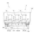
- FIG. 2 is a longitudinal sectional view of the windmill shown in FIG. 1 and shows a movable part between the tower and the nacelle.
- FIG. 3 is a plan view showing the arrangement of the wind turbine driving device in the movable part shown in FIG.
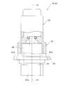
- FIG. 4 is a partial cross-sectional view of the wind turbine driving device shown in FIG.
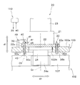
- FIG. 5 is a partial cross-sectional view of the installation portion of the wind turbine driving device shown in FIG.
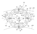
- FIG. 6 is a plan view showing an arrangement of fasteners for installing the windmill drive device shown in FIG. 4.
- the windmill driving device 10 described here is installed so as to be able to swing in the pitch direction with respect to a nacelle 103 that is rotatably installed with respect to a tower 102 of the windmill 101 or a rotor 104 attached to the nacelle 103.
- the blade 105 is driven. That is, the windmill drive device 10 described here can be used as a yaw drive device that yaw-drives the nacelle 103 to rotate with respect to the tower 102 of the windmill 101, and further to the nacelle-side rotor 104. It can also be used as a pitch drive device that drives the shaft of the blade 105 to rotate. However, in the illustrated example described below, the windmill drive device functions as a yaw drive device.
- the windmill 101 has a tower 102, a nacelle 103, a rotor 104 as a main shaft portion, a blade 105 as a blade, and the like.
- the tower 102 is installed so as to extend vertically upward from the ground.
- the nacelle 103 is rotatably installed with respect to the upper part of the tower 102.
- the rotation of the nacelle 103 with respect to the tower 102 is a rotation around the longitudinal direction of the tower 102 and is a so-called yaw rotation.
- the nacelle 103 rotates with respect to the tower 102 by being driven by the wind turbine driving device 10 described in detail later.
- a power transmission shaft, a generator, and the like are arranged inside the nacelle 103.
- the rotor 104 is connected to the power transmission shaft and is rotatable with respect to the nacelle 103.
- a plurality of blades 105 (three in the example shown in FIG. 1) are provided.
- the blade 105 extends from the rotor 104 in a radial direction about the rotation axis of the rotor 104 with respect to the nacelle 103.
- the plurality of blades 105 are arranged at an equal angle from each other.
- Each blade 105 can rotate in the pitch direction, in other words, can rotate with respect to the rotor 104 around the longitudinal direction. That is, the connection part of the blade 105 to the rotor 104 is a movable part.
- the blade 105 is rotationally driven by a windmill drive device provided as a pitch drive device, and the windmill drive device as the pitch drive device is configured in the same manner as the windmill drive device 10 as a yaw drive measure described later. .
- FIG. 2 is an enlarged cross-sectional view showing a portion where the nacelle 103 is installed so as to be rotatable with respect to the tower 102 in the wind turbine 101.
- the wind turbine driving device 10 is illustrated as an outline view instead of a cross-sectional view.
- the nacelle 103 is rotatably installed via a bearing 106 with respect to the upper portion of the tower 102 at the bottom 103a.
- a ring gear 107 having inner teeth formed on the inner periphery is fixed to the top of the tower 102.
- the teeth of the ring gear 107 are not limited to those provided on the inner periphery, but may be provided on the outer periphery. In the drawing, each tooth of the inner teeth of the ring gear 107 is omitted.
- a plurality of wind turbine drive devices 10 are installed in the nacelle 103.
- the windmill drive device 10 includes a meshing portion 24 a that meshes with the internal teeth of the ring gear 107.
- the nacelle 103 that is one of the movable parts of the windmill 101 can be rotated with respect to the tower 102 that is the other movable part of the windmill 101.
- the ring gear 107 is formed in a circumferential shape and has a central axis Cm.
- the nacelle 103 rotates around the central axis Cm of the ring gear 107.
- the center axis Cm of the ring gear 107 coincides with the longitudinal direction of the tower 102.
- the direction parallel to the center axis Cm of the ring gear 107 is also simply referred to as “axial direction dl”.
- a pair of windmill drive unit 5 is provided.
- the pair of wind turbine driving device units 5 are arranged so as to be rotationally symmetric about the center axis Cm of the ring gear 107.
- Each windmill drive unit 5 includes three windmill drive units 10.
- a total of six drive device main bodies 20 included in the pair of wind turbine drive device units 5 are provided along a circumference cl1 (see FIG. 3) centering on the central axis Cm of the ring gear 107.
- the three wind turbine drive devices 10 included in each wind turbine drive device unit 5 are arranged in order at regular intervals along the circumference cl1.
- the windmill drive device 10 includes a drive device main body 20 fixed to the nacelle 103 and a fastener 30 for fixing the drive device main body 20 to the nacelle 103. Furthermore, the windmill drive device 10 described here includes a sensor 40 for detecting an abnormality of the drive device body 20. The sensor 40 measures a change in the state of the fastener 30. By using this sensor 40, it is possible to quickly and accurately detect an abnormal state of the drive device body 20, as will be described later. Hereinafter, each component of the windmill drive device 10 will be described in order.
- the drive device body 20 includes an output shaft 24 having a meshing portion 24 a that meshes with the ring gear 107, a case 21 that rotatably holds the output shaft 24, and an electric motor 23 that is fixed to the case 21. ,have.
- the drive device body 20 further includes a connecting portion 25 that connects the electric motor 23 and the output shaft 24.
- the connecting portion 25 is accommodated in the case 21.
- the connecting portion 25 decelerates the input from the electric motor 23 and transmits it to the output shaft 24.
- an eccentric oscillating gear type or a planetary gear type reduction mechanism, or a reduction mechanism combining an eccentric oscillating gear type and a planetary gear type can be employed.
- the end of the output shaft 24 on the side away from the connecting portion 25 extends from the case 21.
- a meshing portion 24 a is formed at a portion of the output shaft 24 extending from the case 21.
- the meshing portion 24 a of the output shaft 24 extends into a through hole 103 b formed in the bottom 103 a of the nacelle 103 and meshes with the ring gear 107.
- the meshing portion 24 a is formed in a shape corresponding to the ring gear 107.
- the meshing portion 24 a forms a pinion gear having external teeth that mesh with the internal teeth of the ring gear 107.
- the windmill drive device 10 has a longitudinal axis that coincides with the rotational axis Cr of the output shaft 24. In a state where the windmill driving device 10 is fixed to the nacelle 103, the rotation axis Cr of the output shaft 24 is parallel to the axial direction dl of the windmill 101.
- case 21 will be described.
- the case 21 is formed in a cylindrical shape.
- the case 21 is disposed such that its longitudinal axis is located on the rotation axis Cr.
- the case 21 is open at both ends along the rotation axis Cr.
- the meshing portion 24a of the output shaft 24 is exposed from the opening of the case 21 on the tower 102 side.
- An electric motor 23 is attached to the opening of the case 21 on the side opposite to the tower 102.
- the case 21 has a flange 22.
- the flange 22 is formed in an annular shape and extends along a circumference cl ⁇ b> 3 centering on the rotation axis Cr of the output shaft 24.
- a through hole 22 a is formed in the flange 22.
- a large number of through holes 22 a are formed on the circumference around the rotation axis Cr of the output shaft 24. In the illustrated example, twelve through holes 22a are formed. As shown in FIGS. 4 and 5, the through hole 22a extends in the axial direction dl.
- the fastener 30 passes through the flange 22 through a through hole 22 a formed in the flange 22 of the drive device main body 20.
- a through hole 103 c is formed in the bottom portion 103 a of the nacelle 103 at a position facing the through hole 22 a of the flange 22.
- the fastener 30 passes through the through hole 22 a of the drive device main body 20, and further extends into the through hole 103 c of the nacelle 103.
- the fastener 30 includes a bolt 30a and a nut 30b.
- the bolt 30 a passes through the drive device body 20 of the drive device body 20 and the bottom 103 a of the nacelle 103.
- the nut 30 b is screwed from the nacelle 103 side to a bolt 30 a that penetrates the drive device main body 20 and the nacelle 103 in this order.
- the through holes 103c of the nacelle 103 are formed at 12 locations corresponding to the through holes 22a.
- a fastener 30 including a bolt 30 a and a nut 30 b is provided for each through hole 22 a of the drive device main body 20.
- the drive device main body 20 is attached to the nacelle 103 at 12 locations by twelve fasteners 30.
- the fastener 30 is configured by a bolt 30 a, and the driving device main body 20 can be fixed to the nacelle 103 by the bolt 30 a meshing with the through hole 103 c of the nacelle 103.
- the sensor 40 measures a change in the state of the fastener 30.
- the sensor 40 may be configured by a known sensor that measures one or more of the load applied to the fastener 30, the displacement of the fastener 30 relative to the nacelle 103, and the relative position of the fastener 30 relative to the nacelle 103.
- an axial force sensor is used as the sensor 40, and a load in a specific direction applied to the fastener 30 can be measured.
- a magnetic sensor or photoelectric sensor as the sensor 40, the position and displacement of the fastener 30 can be measured in a non-contact manner.
- the senor 40 is held by being fixed to one of the movable parts, that is, the nacelle 103, using a jig 49.
- the axial force sensor forming the sensor 40 is in contact with the head of the bolt 30 a forming the fastener 30.
- the present invention is not limited to this example, and the sensor 40 may abut on the tip of the bolt 30a opposite to the head as shown by a two-dot chain line in FIG. You may make it contact
- the sensor 40 is electrically connected to the control device 110.
- An electrical signal related to the measurement result output from the sensor 40 is transmitted to the control device 110.
- the control device 110 can grasp the change in the load applied to the fastener 30 and the displacement of the fastener 30.
- the control device 110 controls the components of the windmill 101 such as the windmill drive device 10 based on the measurement result of the sensor 40.
- the plurality of wind turbine drive devices 10 included in the wind turbine drive device unit 5 are operated in synchronization.
- the nacelle 103 and the blade 105 which are heavy objects, can be rotated with respect to the tower 102 and the rotor 104, respectively.
- Each wind turbine driving device 10 operates based on a control signal from the control device 110.
- the control device 110 may transmit a drive signal to the windmill drive device 10 included in the windmill drive device unit 5.
- the meshing portion 24a of the failed windmill driving device 10 meshes with the ring gear 107, and the operation of the movable part is restricted. Therefore, when the meshing portion 24a of another normal windmill drive device 10 included in the windmill drive device unit 5 operates, a large stress is generated between the meshing portion 24a of the windmill drive device 10 and the ring gear 107.
- the wind turbine driving device 10 has a sensor 40.
- the sensor 40 measures a change in the state of the fastener 30 for installing the windmill driving device 10 on one of the movable parts of the windmill 101, for example, the nacelle 103.
- the sensor 40 transmits an electrical signal indicating the state of the fastener 30 to the control device 110.
- the control device 110 can monitor the electrical signal transmitted from the sensor 40 and detect an abnormality of the windmill drive device 10. When an abnormality is detected, the control device 110 issues an alarm or the like indicating the occurrence of the abnormality and stops driving the windmill drive device 10. Thereby, the further damage of the drive device 10 for windmills or the ring gear 107 can be avoided.
- a change in the state of the fastener 30 is measured.
- the simulation was repeated, the following tendency was confirmed. That is, when another normal windmill drive device 10 is driven in a state where one of the plurality of windmill drive devices 10 has failed and is fixed, a large load is applied to the fastener 30 for mounting the windmill drive device 10 on the structure. And the fastener 30 was damaged. In addition, such a tendency is consistent with a problem that actually occurs during operation of the wind turbine. In the first place, when the state of the fastener 30 changes greatly, the windmill drive device 10 moves relative to the windmill body, and the installation state of the windmill drive device 10 changes greatly.
- Such a sensor 40 includes a change in the state of the fastener 30 in the tangential direction dt with respect to the circumference cl6 about the center axis Cm of the ring gear 107, and a fastener in the radial direction dr about the center axis Cm of the ring gear.
- a change in the state of 30 and the change in the state of the fastener 30 in the axial direction dl parallel to the center axis Cm of the ring gear 107 is measured.
- the fastener 30 is most likely to undergo the largest state change in any one of the tangential direction dt, the radial direction dr, and the axial direction dl. Become. Therefore, the sensor 40 is one of a change in the state of the fastener 30 in the tangential direction dt, a change in the state of the fastener 30 in the radial direction dr, and a change in the state of the fastener 30 in the axial direction dl.
- the abnormal state of the windmill drive device 10 can be detected more quickly and more accurately.
- the sensor 40 performs all of the change in the state of the fastener 30 in the tangential direction dt, the change in the state of the fastener 30 in the radial direction dr, and the change in the state of the fastener 30 in the axial direction dl. By detecting it, it becomes possible to detect the abnormal state of the windmill drive device 10 very quickly and with high accuracy.
- the state of the fastener 30 is likely to change greatly in a direction parallel to the axis Cb or in a direction perpendicular to the axis Cb. . Therefore, in consideration of the shape of the fastener 30, the sensor 40 changes the state of the fastener 30 in the direction parallel to the axis Cb of the fastener 30 and the direction orthogonal to the axis Cb of the fastener 30. It is preferable to measure at least one of the changes in the state of the fastener 30.
- the longitudinal axis Cb of the fastener 30 is parallel to the rotational axis Cr of the wind turbine driving device 10 and the central axis Cm of the ring gear 107. That is, the longitudinal axis Cb of the fastener 30 is parallel to the axial direction dl described above and is orthogonal to the tangential direction dt and the radial direction dr described above. In the illustrated example, the state of the fastener 30 is in one of the tangential direction dt, the radial direction dr, or the axial direction dl, in other words, in a direction parallel to or perpendicular to the longitudinal axis Cb of the fastener 30. It becomes very easy to change. Therefore, the sensor 40 measures the change in the state of the fastener 30 in these directions, so that the abnormal state of the windmill drive device 10 can be detected very quickly and extremely accurately.
- the drive device main body 20 of the windmill drive device 10 has a case 21 having a flange 22 through which a fastener 30 passes, and a meshing portion 24a. And an output shaft 24 supported by the motor.
- a plurality of fasteners 30 are arranged around the axis of the output shaft 24, that is, around the rotation axis Cr of the wind turbine driving device 10.
- a separate sensor 40 that measures a change in the state of the fastener 30 is provided for each fastener 30. By using the separate sensor 40 in this way, the state of each fastener 30 can be more accurately evaluated.
- the sensor 40 includes a first fastener 31 located on the most side along a circumference cl6 centered on the center axis Cm of the ring gear 107, and a circumference cl6 centered on the center axis Cm of the ring gear 107.
- the second fastener 32 located on the most other side, the third fastener 33 located farthest from the central axis Cm along the radial direction dr about the central axis Cm of the ring gear 107, and the ring gear A change in the state of at least one of the fourth fasteners 34 located closest to the central axis Cm along the radial direction dr centering on the central axis Cm 107 is measured. It is preferable.
- the abnormal state of the wind turbine driving device 10 can be detected more quickly and more accurately by detecting a change in the state of one or more of the first to fourth fasteners 31, 32, 33, 34 using the sensor 40. Can be detected. Further, the sensor 40 measures all the state changes of the first to fourth fasteners 31, 32, 33, and 34, thereby detecting the abnormal state of the wind turbine driving device 10 extremely quickly and accurately. It becomes possible.
- the first sensor 41 is provided corresponding to the first fastener 31 located on the most side along the circumference cl ⁇ b> 6 centering on the central axis Cm of the ring gear 107.
- a second sensor 42 is provided corresponding to the second fastener 32 located on the most other side along the circumference cl6 centered on the central axis Cm of the ring gear 107.
- a third sensor 43 is provided corresponding to the third fastener 33 that is located farthest from the central axis Cm along the radial direction dr centering on the central axis Cm of the ring gear 107.
- a fourth sensor 44 is provided corresponding to the fourth fastener 34 located closest to the central axis Cm along the radial direction dr centering on the central axis Cm.
- the first to fourth sensors 41, 42, 43, and 44 that are separate from each other with respect to the first to fourth fasteners 31, 32, 33, and 34 that are most likely to be loaded. Can be used to accurately and independently measure state changes. Therefore, it is possible to detect an abnormal state of the windmill drive device 10 very quickly and very accurately.
- the sensor 40 detects a change in state of the fastener 30 located in the region R ⁇ where the meshing pressure angle ⁇ is within a predetermined angle, for example, the region R ⁇ where the meshing pressure angle ⁇ is within ⁇ 20 °. . More preferably, a change in state is detected by the sensor 40 for the fastener 30 located in the region R ⁇ where the meshing pressure angle ⁇ is within a range of ⁇ 10 °, and most preferably, at a position where the meshing pressure angle ⁇ is 0 °. The sensor 40 detects a change in the state of the disposed fastener 30.
- the angle of a straight line that passes through the rotation axis Cr with respect to the tangent t ⁇ at the rotation axis Cr to is referred to as a meshing pressure angle ⁇ .
- a region R ⁇ surrounded by the straight line l ⁇ x and the straight line l ⁇ y is a region R ⁇ in which the meshing pressure angle ⁇ is within a range of ⁇ 20 °.
- the above-described third fastener 33 and fourth fastener 34 are located in a region R ⁇ where the meshing pressure angle ⁇ is within a range of ⁇ 20 °.
- the presence / absence of an abnormal state of the wind turbine drive device 10 may be determined by comparing state changes of the plurality of fasteners 30.
- the abnormal state of the windmill drive device 10 is compared.
- the presence or absence may be determined. In this case, the abnormal state of the wind turbine driving device 10 can be detected very quickly and with high accuracy.
- wind turbine driving device 10 is installed in one structure in the movable part of wind turbine 101 and meshes with ring gear 107 installed in the other structure in the movable part of wind turbine 101.
- the drive device main body 20 having the meshing portion 24a, the fastener 30 that fixes the drive device main body 20 to one structure, the sensor 40 that measures the change in the state of the fastener 30, and the change in the state of the fastener 30.
- a sensor 40 for measurement According to such a windmill drive device 10, an abnormal state of the windmill drive device 10 can be detected quickly and accurately.
- a pair of wind turbine driving device units 5 is provided in a movable part that rotates the nacelle 103 with respect to the tower 102, and each wind turbine driving device unit 5 includes three units.
- a wind turbine driving device 10 is included.
- the present invention is not limited to this example, and only one windmill drive unit 5 may be provided in the movable part of the windmill 101, or three or more windmill drive units 5 may be provided. Also good. Further, the windmill drive unit 5 may include two windmill drive units 10 or may include four or more windmill drive units 10.
Landscapes
- Engineering & Computer Science (AREA)
- Life Sciences & Earth Sciences (AREA)
- Sustainable Development (AREA)
- Sustainable Energy (AREA)
- Chemical & Material Sciences (AREA)
- Combustion & Propulsion (AREA)
- Mechanical Engineering (AREA)
- General Engineering & Computer Science (AREA)
- Wind Motors (AREA)
- Gear Transmission (AREA)
Priority Applications (2)
| Application Number | Priority Date | Filing Date | Title |
|---|---|---|---|
| EP16792454.7A EP3296564B1 (en) | 2015-05-12 | 2016-04-06 | Drive device for wind turbines, drive device unit for wind turbines, and wind turbine |
| DK16792454.7T DK3296564T3 (da) | 2015-05-12 | 2016-04-06 | Drivanordning for vindturbiner, drivanordningsenhed for vindturbiner og vindturbine |
Applications Claiming Priority (2)
| Application Number | Priority Date | Filing Date | Title |
|---|---|---|---|
| JP2015-097710 | 2015-05-12 | ||
| JP2015097710A JP6580367B2 (ja) | 2015-05-12 | 2015-05-12 | 風車用駆動装置、風車用駆動装置ユニット及び風車 |
Publications (1)
| Publication Number | Publication Date |
|---|---|
| WO2016181729A1 true WO2016181729A1 (ja) | 2016-11-17 |
Family
ID=57247881
Family Applications (1)
| Application Number | Title | Priority Date | Filing Date |
|---|---|---|---|
| PCT/JP2016/061313 Ceased WO2016181729A1 (ja) | 2015-05-12 | 2016-04-06 | 風車用駆動装置、風車用駆動装置ユニット及び風車 |
Country Status (4)
| Country | Link |
|---|---|
| EP (1) | EP3296564B1 (da) |
| JP (1) | JP6580367B2 (da) |
| DK (1) | DK3296564T3 (da) |
| WO (1) | WO2016181729A1 (da) |
Cited By (8)
| Publication number | Priority date | Publication date | Assignee | Title |
|---|---|---|---|---|
| JP2018003820A (ja) * | 2016-07-08 | 2018-01-11 | ナブテスコ株式会社 | 風車駆動システム及び風車 |
| JP2018003816A (ja) * | 2016-07-08 | 2018-01-11 | ナブテスコ株式会社 | 風車駆動システム及び風車 |
| JP2018091314A (ja) * | 2016-12-07 | 2018-06-14 | ナブテスコ株式会社 | 駆動装置、駆動装置ユニット及び風車 |
| JP2018091309A (ja) * | 2016-12-07 | 2018-06-14 | ナブテスコ株式会社 | 風車駆動システム及び風車 |
| JP2018091251A (ja) * | 2016-12-05 | 2018-06-14 | ナブテスコ株式会社 | 風車用駆動装置、風車用駆動装置ユニット及び風車 |
| CN108458053A (zh) * | 2017-02-21 | 2018-08-28 | 斯凯孚公司 | 用于状况监测的被仪表化的轴 |
| CN110869643A (zh) * | 2017-07-04 | 2020-03-06 | Zf 腓德烈斯哈芬股份公司 | 能枢转的传动装置 |
| CN113530762A (zh) * | 2020-04-21 | 2021-10-22 | 纳博特斯克有限公司 | 状态监视装置以及状态监视方法 |
Families Citing this family (1)
| Publication number | Priority date | Publication date | Assignee | Title |
|---|---|---|---|---|
| JP7599282B2 (ja) | 2020-05-21 | 2024-12-13 | ナブテスコ株式会社 | 締結構造および風車 |
Citations (4)
| Publication number | Priority date | Publication date | Assignee | Title |
|---|---|---|---|---|
| US20100052320A1 (en) * | 2008-08-27 | 2010-03-04 | Till Hoffmann | Method and apparatus for load measurement in a wind turbine |
| JP2011047307A (ja) * | 2009-08-26 | 2011-03-10 | Nabtesco Corp | 風車用減速装置 |
| US20120134809A1 (en) * | 2011-12-06 | 2012-05-31 | General Electric Company | System and method for detecting loads transmitted through a blade root of a wind turbine rotor blade |
| WO2014005735A1 (de) * | 2012-07-03 | 2014-01-09 | Wobben Properties Gmbh | Überwachte bauteilverbindung, windenergieanlage, verfahren zur überwachung einer bauteilverbindung auf ein ungewolltes lösen der bauteilverbindung im verbundenen zustand |
Family Cites Families (2)
| Publication number | Priority date | Publication date | Assignee | Title |
|---|---|---|---|---|
| US5278773A (en) * | 1990-09-10 | 1994-01-11 | Zond Systems Inc. | Control systems for controlling a wind turbine |
| US20110158806A1 (en) * | 2009-04-15 | 2011-06-30 | Arms Steven W | Wind Turbines and Other Rotating Structures with Instrumented Load-Sensor Bolts or Instrumented Load-Sensor Blades |
-
2015
- 2015-05-12 JP JP2015097710A patent/JP6580367B2/ja active Active
-
2016
- 2016-04-06 EP EP16792454.7A patent/EP3296564B1/en active Active
- 2016-04-06 WO PCT/JP2016/061313 patent/WO2016181729A1/ja not_active Ceased
- 2016-04-06 DK DK16792454.7T patent/DK3296564T3/da active
Patent Citations (4)
| Publication number | Priority date | Publication date | Assignee | Title |
|---|---|---|---|---|
| US20100052320A1 (en) * | 2008-08-27 | 2010-03-04 | Till Hoffmann | Method and apparatus for load measurement in a wind turbine |
| JP2011047307A (ja) * | 2009-08-26 | 2011-03-10 | Nabtesco Corp | 風車用減速装置 |
| US20120134809A1 (en) * | 2011-12-06 | 2012-05-31 | General Electric Company | System and method for detecting loads transmitted through a blade root of a wind turbine rotor blade |
| WO2014005735A1 (de) * | 2012-07-03 | 2014-01-09 | Wobben Properties Gmbh | Überwachte bauteilverbindung, windenergieanlage, verfahren zur überwachung einer bauteilverbindung auf ein ungewolltes lösen der bauteilverbindung im verbundenen zustand |
Cited By (20)
| Publication number | Priority date | Publication date | Assignee | Title |
|---|---|---|---|---|
| JP2018003816A (ja) * | 2016-07-08 | 2018-01-11 | ナブテスコ株式会社 | 風車駆動システム及び風車 |
| WO2018008753A1 (ja) * | 2016-07-08 | 2018-01-11 | ナブテスコ株式会社 | 風車駆動システム及び風車 |
| WO2018008754A1 (ja) * | 2016-07-08 | 2018-01-11 | ナブテスコ株式会社 | 風車駆動システム及び風車 |
| US11619208B2 (en) | 2016-07-08 | 2023-04-04 | Nabtesco Corporation | Wind turbine drive system and wind turbine |
| JP2018003820A (ja) * | 2016-07-08 | 2018-01-11 | ナブテスコ株式会社 | 風車駆動システム及び風車 |
| EP3550141A4 (en) * | 2016-12-05 | 2020-07-08 | Nabtesco Corporation | WIND TURBINE DRIVE DEVICE, WIND TURBINE DRIVE DEVICE AND WIND TURBINE |
| JP2018091251A (ja) * | 2016-12-05 | 2018-06-14 | ナブテスコ株式会社 | 風車用駆動装置、風車用駆動装置ユニット及び風車 |
| US11274655B2 (en) | 2016-12-05 | 2022-03-15 | Nabtesco Corporation | Wind turbine driving device, wind turbine driving device unit, and wind turbine |
| CN109983222A (zh) * | 2016-12-05 | 2019-07-05 | 纳博特斯克有限公司 | 风车用驱动装置、风车用驱动装置单元以及风车 |
| CN109983222B (zh) * | 2016-12-05 | 2021-11-09 | 纳博特斯克有限公司 | 风车用驱动装置、风车用驱动装置单元以及风车 |
| JP2018091309A (ja) * | 2016-12-07 | 2018-06-14 | ナブテスコ株式会社 | 風車駆動システム及び風車 |
| EP3553309A4 (en) * | 2016-12-07 | 2020-07-29 | Nabtesco Corporation | DRIVE DEVICE, DRIVE DEVICE UNIT AND WIND TURBINE |
| EP3553310A4 (en) * | 2016-12-07 | 2020-07-29 | Nabtesco Corporation | WINDMILL AND WINDMILL DRIVE SYSTEM |
| US11015575B2 (en) | 2016-12-07 | 2021-05-25 | Nabtesco Corporation | Wind turbine drive system and wind turbine |
| US11047366B2 (en) | 2016-12-07 | 2021-06-29 | Nabtesco Corporation | Driving device, driving device unit and wind turbine |
| JP2018091314A (ja) * | 2016-12-07 | 2018-06-14 | ナブテスコ株式会社 | 駆動装置、駆動装置ユニット及び風車 |
| CN108458053A (zh) * | 2017-02-21 | 2018-08-28 | 斯凯孚公司 | 用于状况监测的被仪表化的轴 |
| CN108458053B (zh) * | 2017-02-21 | 2022-08-12 | 斯凯孚公司 | 用于状况监测的被仪表化的轴 |
| CN110869643A (zh) * | 2017-07-04 | 2020-03-06 | Zf 腓德烈斯哈芬股份公司 | 能枢转的传动装置 |
| CN113530762A (zh) * | 2020-04-21 | 2021-10-22 | 纳博特斯克有限公司 | 状态监视装置以及状态监视方法 |
Also Published As
| Publication number | Publication date |
|---|---|
| EP3296564B1 (en) | 2020-07-29 |
| DK3296564T3 (da) | 2020-10-12 |
| JP6580367B2 (ja) | 2019-09-25 |
| EP3296564A1 (en) | 2018-03-21 |
| EP3296564A4 (en) | 2019-03-13 |
| JP2016211497A (ja) | 2016-12-15 |
Similar Documents
| Publication | Publication Date | Title |
|---|---|---|
| JP6580367B2 (ja) | 風車用駆動装置、風車用駆動装置ユニット及び風車 | |
| CN104011515B (zh) | 用于监控传动系的方法、计算单元和装置 | |
| US11473564B2 (en) | System and method for monitoring a wind turbine pitch bearing | |
| JP6407592B2 (ja) | 風力発電装置の異常診断装置および異常診断方法 | |
| US9322284B2 (en) | Mechanism for synchronously varying pitch of a multi-blade rotor | |
| ES2914059T3 (es) | Sistema y método para monitorizar carga de turbina eólica | |
| JP6968532B2 (ja) | 風車用駆動装置、風車用駆動装置ユニット及び風車 | |
| US20110135468A1 (en) | Systems and methods for monitoring a structural health of a wind turbine | |
| US20130180199A1 (en) | Flange connection for a wind turbine and method of connecting parts of a wind turbine | |
| EP3054292B1 (en) | Apparatus and method for diagnosing the abnormality of a bearing | |
| KR20170042728A (ko) | 구동 시스템에서의 조기 에러 검출 방법, 조기 에러 검출 시스템, 상기 시스템을 포함하는 풍력 발전기 및 상기 시스템의 사용 | |
| ES3055975T3 (en) | Azimuth sensors in wind turbines | |
| JP2016146738A (ja) | 電動アクチュエータの故障検知機構および電動アクチュエータの故障検知機構を備えた電動アクチュエータ | |
| US20190383264A1 (en) | Wind turbine drive system and wind turbine | |
| ES2849525T3 (es) | Sistema y procedimiento para monitorizar el movimiento de un elemento de rodillo de un rodamiento | |
| US12072019B2 (en) | Method of adjusting drive mechanism of wind turbine, and method of adjusting drive mechanism | |
| JP7599282B2 (ja) | 締結構造および風車 | |
| RU2707336C2 (ru) | Вращающаяся машина и установка для преобразования энергии | |
| CN103471478A (zh) | 检测风力发电机组导流罩与轮毂装配精度的装置及方法 | |
| JP2017040611A (ja) | 回転機器の状態監視装置 | |
| CN108869195A (zh) | 一种测量风力发电机组叶轮方位角的方法 | |
| WO2026046525A1 (en) | Methods for detecting structural damage of a wind turbine blade and wind turbines | |
| BR102019001020B1 (pt) | Método para monitorar um sistema de afastamento de uma turbina eólica e turbina eólica |
Legal Events
| Date | Code | Title | Description |
|---|---|---|---|
| 121 | Ep: the epo has been informed by wipo that ep was designated in this application |
Ref document number: 16792454 Country of ref document: EP Kind code of ref document: A1 |
|
| NENP | Non-entry into the national phase |
Ref country code: DE |
|
| WWE | Wipo information: entry into national phase |
Ref document number: 2016792454 Country of ref document: EP |