WO2016181732A1 - Interrupteur - Google Patents
Interrupteur Download PDFInfo
- Publication number
- WO2016181732A1 WO2016181732A1 PCT/JP2016/061373 JP2016061373W WO2016181732A1 WO 2016181732 A1 WO2016181732 A1 WO 2016181732A1 JP 2016061373 W JP2016061373 W JP 2016061373W WO 2016181732 A1 WO2016181732 A1 WO 2016181732A1
- Authority
- WO
- WIPO (PCT)
- Prior art keywords
- iron core
- opening
- fixed
- movable
- flange portion
- Prior art date
- Legal status (The legal status is an assumption and is not a legal conclusion. Google has not performed a legal analysis and makes no representation as to the accuracy of the status listed.)
- Ceased
Links
Images






Classifications
-
- H—ELECTRICITY
- H01—ELECTRIC ELEMENTS
- H01F—MAGNETS; INDUCTANCES; TRANSFORMERS; SELECTION OF MATERIALS FOR THEIR MAGNETIC PROPERTIES
- H01F7/00—Magnets
- H01F7/06—Electromagnets; Actuators including electromagnets
- H01F7/08—Electromagnets; Actuators including electromagnets with armatures
- H01F7/16—Rectilinearly-movable armatures
-
- H—ELECTRICITY
- H01—ELECTRIC ELEMENTS
- H01H—ELECTRIC SWITCHES; RELAYS; SELECTORS; EMERGENCY PROTECTIVE DEVICES
- H01H31/00—Air-break switches for high tension without arc-extinguishing or arc-preventing means
- H01H31/26—Air-break switches for high tension without arc-extinguishing or arc-preventing means with movable contact that remains electrically connected to one line in open position of switch
- H01H31/32—Air-break switches for high tension without arc-extinguishing or arc-preventing means with movable contact that remains electrically connected to one line in open position of switch with rectilinearly-movable contact
-
- H—ELECTRICITY
- H01—ELECTRIC ELEMENTS
- H01H—ELECTRIC SWITCHES; RELAYS; SELECTORS; EMERGENCY PROTECTIVE DEVICES
- H01H33/00—High-tension or heavy-current switches with arc-extinguishing or arc-preventing means
- H01H33/02—Details
- H01H33/28—Power arrangements internal to the switch for operating the driving mechanism
- H01H33/38—Power arrangements internal to the switch for operating the driving mechanism using electromagnet
Definitions
- the present invention relates to a switch for a power device, and relates to a switch such as a circuit breaker or a disconnect switch that opens and closes an electric circuit using electromagnetic force.
- the electric power system is provided with a switch such as a circuit breaker for interrupting the overcurrent in order to protect the entire system from the overcurrent, and a disconnector for reliably disconnecting the power equipment from the system.
- a switch such as a circuit breaker for interrupting the overcurrent in order to protect the entire system from the overcurrent, and a disconnector for reliably disconnecting the power equipment from the system.
- a switch such as a circuit breaker for interrupting the overcurrent in order to protect the entire system from the overcurrent, and a disconnector for reliably disconnecting the power equipment from the system.
- a switch such as a circuit breaker for interrupting the overcurrent in order to protect the entire system from the overcurrent, and a disconnector for reliably disconnecting the power equipment from the system.
- an oil damper or the like is used to stop the movable electrode that moves at high speed by the opening operation (see, for example, Patent Document 1).
- the oil damper proposed in Patent Document 1 is provided as a buffer mechanism at the end of the movable range of the movable part because of the need to reduce the impact during operation. With this oil damper, it is possible to extend the life of the switch.
- the present invention has been made in order to solve the above-described problems, and is capable of performing an opening operation and a closing operation while suppressing an impact, and includes a mechanism for generating an electromagnetic braking force inside the fixed iron core.
- the object is to provide a low-cost and space-saving switch.
- the switch according to the present invention is A fixed electrode, and a movable electrode capable of contacting and separating from the fixed electrode;
- An electromagnetic operating section for opening and closing the fixed electrode and the movable electrode,
- the electromagnetic operating section includes a fixed iron core, a movable iron core that moves inside the fixed iron core in the opening and closing directions of the fixed electrode and the movable electrode, An opening spring for applying a load in the opening direction to the movable iron core;
- the fixed iron core is A fixed first flange portion projecting perpendicularly in the opening and closing direction from both side wall surfaces inside the fixed iron core;
- a fixed second flange portion projecting perpendicularly in the opening / closing direction from both side wall surfaces inside the fixed iron core, spaced apart from the fixed first flange portion on the opening side of the fixed first flange portion;
- a first magnetic field shielding member made of a magnetic conductor is provided at the inner front end of the fixed first flange portion,
- a second eddy current induction member made of a non-magnetic conductor electrically connected to the second magnetic field shielding member is provided at an inner tip of the fixed second flange portion at least in the opening / closing direction of the second magnetic field shielding member.
- the movable iron core is From the movable iron core axis of the movable iron core, protrudes on both sides perpendicular to the opening and closing direction, A movable first flange portion facing the first magnetic field shielding member at an opening position of the movable core; A movable second flange portion facing the second magnetic field shielding member at the opening position of the movable iron core;
- the electromagnetic operation unit is A closing coil disposed coaxially with the axis of the movable iron core on the closing direction side of the fixed first flange portion, and moving the movable iron core in the closing direction with electromagnetic force; Arranged coaxially with the axis of the movable core on the opening direction side of the fixed first flange portion and on the closing direction side of the fixed second flange portion, and the movable iron core is moved in the opening direction by electromagnetic force An opening coil to cause And a first permanent magnet that attracts the movable iron core to the fixed iron core at a closed position of the movable iron core
- the electromagnetic force generated by the eddy current generated in the magnetic field shielding member during the driving of the movable iron core can be used as a braking force, so that it is possible to provide a switch with a small size and a small number of parts.
- FIG.1 It is a cross-sectional schematic diagram of the switch concerning Embodiment 1 of this invention. It is a principal part enlarged view of Fig.1 (a). It is a graph which shows the transition of the resultant force of each spring load which concerns on Embodiment 1 of this invention, and the transition of the resultant force of the attraction
- the closed state refers to a state in which the switch closes the circuit, and the fixed electrode and the movable electrode are electrically connected.
- the open state refers to a state in which the circuit is open.
- the disconnected state is the same as the open state in that the circuit is opened, but refers to a state in which the fixed electrode and the movable electrode are further separated in order to ensure safety during maintenance or the like.
- the term “magnetic force” simply includes electromagnetic force and permanent magnet force.
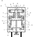
- FIG. 1 (a) to 1 (d) are schematic cross-sectional views of a switch 100 according to Embodiment 1 of the present invention.
- Fig.1 (a) has shown the state which the movable iron core 6 of the switch 100 has stopped in the closed position.
- FIG. 1B shows a state immediately after the movable core 6 of the switch 100 starts the opening operation.
- FIG.1 (c) has shown the state which the movable iron core 6 of the switch 100 has stopped in the open position.
- FIG.1 (d) has shown the state which the movable iron core 6 of the switch 100 has stopped in the disconnection position.
- the switch 100 is left-right symmetric, and the fixed iron core 5 has a shape obtained by extending the cross-sectional shape of FIG.
- the fixed electrode 2 is an electrode whose position is fixed.
- the movable electrode 3 is an electrode that can contact and separate from the fixed electrode 2.
- An insulating rod 4 is connected to the opening side of the movable electrode 3.
- the insulating rod 4 insulates the movable electrode 3 from the movable axis A (first movable axis) connected to the opening side of the insulating rod 4.
- the movable shaft A includes a flange portion A1 at the end on the opening side.
- the movable electrode 3, the insulating rod 4, and the movable shaft A are integrally movable in the opening direction and the closing direction.
- the movable shaft B (second movable shaft) includes a hollow buffer B1 on the closing side, and the opening side end B2 is housed in a stationary iron core 5 that does not move and can move in the opening and closing direction.
- the iron core 6 is connected to the closed end 6H.
- the buffer B1 includes a hole B1K1 at the end B1K on the closing side.
- the flange portion A1 of the movable shaft A is accommodated inside the buffer portion B1, and the shaft A2 of the movable shaft A projects through the hole B1K1 to the closing side.
- the outer diameter of the flange portion A1 is larger than the inner diameter of the hole B1K1, and the end portion of the compressed contact pressure spring S1 is provided between the inner wall surface B1H on the opening side of the buffer portion B1 and the flange portion A1 of the movable shaft A. Therefore, even if the movable shaft B moves in the opening / closing direction, the movable shaft A does not move completely in conjunction with each other.
- the fixed iron core 5 covers the movable iron core 6, restricts the movable range of the movable iron core 6 in the opening / closing direction, and forms a magnetic circuit.
- the movable shaft C has one end on the closing side connected to the opening side end 6K of the movable iron core 6.
- the axis C ⁇ b> 2 of the movable shaft C protrudes to the outside of the fixed iron core 5 through a hole formed in the opening side end of the fixed iron core 5.
- the other end portion on the opening side of the movable shaft C is provided with a flange portion C1.
- the movable shaft C is a compression spring having a closed end connected to the open end of the fixed iron core 5 and an open end connected to the flange C1, and is connected to the movable shaft C.
- an opening spring S2 for applying a load in the opening direction is provided.
- the movable shaft B and the movable shaft C may be integrated.
- a spring receiver 7 that receives the movable shaft C at the time of opening is provided so as to surround the movable shaft C.
- the spring receiver 7 is configured to be hollow, and the end on the closing side is fixed to the opening side end surface of the fixed iron core 5.
- One end on the opening side of the disconnector closing spring S3 is connected to the inner wall surface 71H of the end portion on the opening side of the spring receiver 7, and the other end on the closing side of the disconnector closing spring S3 is the bearing plate. 8 is connected to the surface on the opening side.
- a bearing plate restricting projection 72 for restricting the movement of the bearing plate 8 in the opening / closing direction protrudes from the inner side wall surface of the spring receiver 7 perpendicular to the opening / closing direction.
- the disconnector closing spring S ⁇ b> 3 extends to press the bearing plate 8 against the bearing plate restricting protrusion 72.
- FIG. 2 is a schematic cross-sectional view of the electromagnetic operation unit 50 of the switch 100, and is an enlarged view of a main part of FIG.
- the fixed iron core 5 has a fixed first flange portion 51 that protrudes from the inner side wall surfaces in a large vertical direction in the opening and closing direction, and a fixed second flange that protrudes inward from the fixed first flange portion 51 with a gap on the opening side.
- a flange portion 52 is provided.
- the fixed iron core 5 includes a closing position holding portion 53 that protrudes in the opening direction from the inner end of the fixed first flange portion 51.
- a permanent magnet M1 (first permanent) is provided outside (closed inside) the closed position holding portion 53 so as to attract and hold a movable iron core 6 (described later) to the fixed core 5 at the closed position via the closed position holding portion 53. Magnet).
- the inner wall of the opening side end portion of the fixed iron core 5 is provided with a disconnection position holding portion 54 that protrudes toward the closing side so as to surround the periphery of the movable shaft C.
- a permanent magnet M2 (second permanent magnet) that holds the movable iron core 6 at the disconnection position via the disconnection position holding unit 54 is provided outside the disconnection position holding unit 54.
- a magnetic field shielding iron plate F1 (first magnetic field shielding member: a magnetic conductor) having magnetism is fixed to the inner end of the fixed first flange portion 51 of the fixed iron core 5.
- a nonmagnetic eddy current induction copper plate D1 (first eddy current induction member: nonmagnetic conductor) electrically connected to the magnetic field shielding iron plate F1 is disposed on the opening side of the magnetic field shielding iron plate F1. It is connected flush with F1.
- a magnetic field shielding iron plate F2 (second magnetic field shielding member: a conductor having magnetism) is fixed to the inner end of the fixed second flange portion 52 of the fixed iron core 5, and on the opening side of the magnetic field shielding iron plate F2,
- An eddy current induction copper plate D2 (second eddy current induction member: nonmagnetic conductor) electrically connected to the magnetic field shielding iron plate F2 is flush with the magnetic field shielding iron plate F2.
- the base of the fixed first flange 51 on the closing side is provided with a closing coil 91 coaxially with the axis of the movable iron core 6.
- an opening coil 92 disposed coaxially with the axis of the movable iron core 6 is provided between the fixed first flange portion 51 and the fixed second flange portion 52, and the opening side of the fixed second flange portion 52 Is provided with a disconnecting coil 93 coaxially with the axis of the movable iron core 6.
- the movable iron core 6 has a movable first flange portion 61 that protrudes outwardly perpendicularly to the opening / closing direction at the closing end of the moving iron shaft 60 and an opening end of the moving iron shaft 60 in the opening / closing direction. And a movable second flange portion 62 that projects vertically outwardly.
- the movable first flange portion 61 of the movable iron core 6 is located inside the closed coil 91, and the movable second flange portion 62 is Located inside the opening coil 92.
- the movable iron core 6 is in the open position shown in FIG. 1 (c)
- the movable first flange portion 61 of the movable iron core 6 is located inside the magnetic field shielding iron plate F1
- the movable second flange portion 62 is It is located inside the magnetic field shielding iron plate F2.
- the movable iron core 6 is at the disconnecting position shown in FIG. 1D, the movable first flange portion 61 of the movable iron core 6 is located inside the opening coil 92, and the movable second flange portion 62 is It is located inside the disconnecting coil 93.
- each of the closing coil 91, the opening coil 92, and the disconnecting coil 93 is provided with a drive circuit that charges a capacitor and discharges the coil.
- a battery or a DC power source may be used as a power source.
- FIG. 3 shows the transition of the resultant force of the three spring loads of the contact pressure spring S1, the opening spring S2 and the disconnector closing spring S3, and the permanent magnets M1 and M2 with respect to the movable iron core 6 when the coils 91 to 93 are not energized. It is a graph which shows transition of the resultant force of adsorption power.
- the solid line indicates the resultant force of the spring load
- the dotted line indicates the transition of the resultant force of the attractive force of the permanent magnets M1 and M2.
- the vertical axis indicates the magnitude of the spring load and the attracting force of the permanent magnets M1 and M2, the plus direction indicates the load in the opening direction for the spring load, and the closing direction for the attracting force of the permanent magnets M1 and M2. Indicates the load. It is drawn with the opening and closing directions reversed so that the magnitude of the force can be visually compared.
- the negative direction of the vertical axis is reversed, and the spring load indicates the closing direction, and the attracting force of the permanent magnets M1 and M2 indicates the load in the opening direction.
- the horizontal axis indicates the position of the movable iron core 6.
- the movable core 6 shown in FIG. 1 (a) In the state where the movable core 6 shown in FIG. 1 (a) is in the closed position, the movable core 6 is closed by the closed position holding portion 53 of the fixed core 5 and the inner wall surface 5H on the closed side by the attractive force of the permanent magnet M1. To be adsorbed. At this time, the contact pressure spring S1 and the opening spring S2 are held in a compressed state as compared with the state in which the movable iron core 6 shown in FIG. 1C is in the opening position. As shown in FIG. 3, the condition for maintaining the closed state is that the attracting force of the permanent magnet M1 to the movable iron core 6 is larger than the resultant force of the load of the contact pressure spring S1 and the opening spring S2.
- the open spring S2 is still compressed, but the movable iron core 6 is extended more than when it is in the closed position.
- the opening spring S2 applies a load in the opening direction to the movable iron core 6 through the flange portion C1 at the opening end of the movable shaft C.
- a load is applied to the flange portion C1 also in the opposite closing direction by the disconnector closing spring S3 via the bearing plate 8, and the load of the disconnector closing spring S3 is larger than the load of the opening spring S2. Then, the movable shaft C does not move further in the opening direction.
- the movable iron core 6 Since the movable range of the bearing plate 8 and the disconnector closing spring S3 is restricted by the bearing plate restricting protrusion 72 from the open position to the disconnected position, the movable iron core 6 is held at the open position. Further, at this time, the movable iron core 6 is far away from the permanent magnet M1 and the permanent magnet M2, and therefore is hardly affected by the attracting force of the permanent magnets M1 and M2 at the opening position (c).
- the movable iron core 6 is attracted and held by the disconnection position holding portion 54 of the fixed iron core 5 by the attractive force of the permanent magnet M2.
- the open spring S2 is in a state of being further extended from the closed position, but is still compressed.
- the disconnector closing spring S3 is pressed by the movement of the flange portion C1 of the movable shaft C and is held in a compressed state from the closed position.
- the attracting force by the permanent magnet M2 is larger than the load difference between the load of the disconnector closing spring S3 facing the closing side and the opening spring S2 facing the opening side. It is a condition for being held.
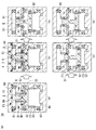
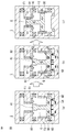
- FIG. 4 (a) to 4 (e) are schematic views showing the opening operation of the electromagnetic operation unit 50 of the switch 100.
- FIG. The movable iron core 6 starts moving in the opening direction from the closed position shown in FIG. 4A and stops moving at the open position shown in FIG.
- the black arrow indicates the magnetic flux generated by the permanent magnet M1
- the white arrow indicates the magnetic flux generated by excitation of the opening coil 92.
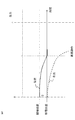
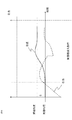
- the graph shown by the solid line in FIG. 5 shows the position of the movable core 6 during the opening operation, that is, until the movable core 6 starts operating from the closed position and stops operating at the closed position.
- the vertical axis indicates the position of the movable iron core 6, and the horizontal axis indicates the elapsed time from the start of the opening operation to the completion of the opening operation.
- the graph shown by the dotted line in FIG. 5 is a graph showing a change in the resultant force of the load acting on the movable iron core 6 during the opening operation.
- the movable iron core 6 has a magnetic force of a permanent magnet (mainly M ⁇ b> 1), an electromagnetic force generated by the flow of magnetic flux by the opening coil 92, and a resultant load of the contact pressure spring S ⁇ b> 1 and the opening spring S ⁇ b> 2.
- the resultant force of each load in FIG. 5 is a force in which the positive side of the vertical axis is directed toward the closing direction and the negative side is directed toward the opening direction.
- the movable iron core 6 In the closed state shown in FIG. 4A, the movable iron core 6 is attracted and held by the closed position holding portion 53 of the fixed iron core 5 and the inner wall surface 5H on the closed side by the magnetic flux generated by the permanent magnet M1.
- the opening coil 92 When performing the opening operation, the opening coil 92 is excited to generate a magnetic flux that cancels the magnetic flux of the permanent magnet M1, as indicated by the white arrow in FIG. 4B.
- the magnetic field shielding iron plate F1 shields the magnetic field from the movable first flange portion 61 of the movable iron core 6 at the corner portion (circle C portion in FIG. 4B) adjacent to the movable first flange portion 61 of the movable iron core 6. There is a magnetic flux passing through the iron plate F1 in the movable direction, and an electromagnetic force is generated in the opening direction by this magnetic flux.
- the movable iron core 6 When the attracting force by the magnetic force (electromagnetic force + permanent magnet force) of the movable iron core 6 with respect to the fixed iron core 5 is smaller than the resultant force of the contact pressure spring S1 and the opening spring S2, the movable iron core 6 is opened. Start moving in the direction. The start of the movement of the movable iron core 6 is a state at T2 in FIG. However, since the movement in the opening / closing direction between the fixed iron core 5 and the movable iron core 6 starts to be small, the influence of the permanent magnet M1 is strong, so the resultant magnetic force generated by the magnetic flux of the opening coil 92 and the permanent magnet M1 is still Working in the closing direction.
- the movable iron core 6 moves in the opening direction due to the resultant load of the contact spring S1 and the opening spring S2, and between the inner wall surface 5H on the closing side of the fixed iron core 5 and the closing side end 6H of the movable iron core 6.
- the distance between is increased, the influence of the permanent magnet M1 is reduced, and the resultant magnetic force acts in the opening direction. Therefore, in the middle of the opening operation, the movable iron core 6 is driven by the resultant force of the contact pressure spring S1, the opening spring S2, and the electromagnetic force of the opening coil 92. This operation corresponds to T2 to T3 in FIG.
- the electromagnetic force acting on the movable iron core 6 works in the opening direction until the middle of the opening operation, but when the movable iron core 6 reaches the position shown in FIG. 61, since the opposing areas of the movable second flange portion 62 and the magnetic field shielding iron plates F1 and F2 are increased, the electromagnetic force in the opening direction due to the magnetic flux of the opening coil 92 does not work.
- FIG. 6A is a diagram illustrating the electromagnetic operation unit 50 in a state where eddy current is generated.
- FIG. 6B shows the state of eddy current when the eddy current induction copper plates D1 and D2 according to the present invention are not attached, and
- FIG. 6C shows the eddy current when the eddy current induction copper plates D1 and D2 are attached.
- the current state is shown.
- a white dotted arrow shown in FIG. 6A indicates the moving direction (opening direction) of the movable core 6, and a white solid arrow indicates the flow of magnetic flux generated by the opening coil 92.
- the elliptical arrows drawn on the magnetic shielding plates F1 and F2 in FIGS. 6B and 6C indicate the direction of eddy current
- the hatched arrows indicate the direction of electromagnetic force generated by the eddy current. Show.
- the magnetic field shielding iron plates F1, F2 and the movable first flange portion 61 and the outer tip of the movable second flange portion 62 are opposed to each other.
- the linkage flux by the opening coil 92 increases, and on the closing side, the linkage flux decreases. Since an eddy current is generated in a direction that cancels this magnetic flux change, the flow of the eddy current is as shown in FIG. Then, an electromagnetic force is generated by the linkage of the magnetic flux of the opening coil 92 to the eddy current flowing through the magnetic shielding plates F1 and F2.
- the direction of the magnetic flux of the opening coil 92 is opposite, but since the direction of the eddy current is also opposite, both electromagnetic forces generated by the eddy current are the same.
- the eddy currents Y and y flowing through the central portions of the magnetic shielding plates F1 and F2 contribute to the braking force to the movable iron core 6, but the eddy currents X and F flowing through the closed ends of the magnetic shielding plates F1 and F2
- the electromagnetic force generated by x and the eddy currents Z and z flowing through the opening side end and the magnetic flux of the opening coil 92 works in the opposite direction to the hatched arrows in FIGS. 6B and 6C.
- the braking force due to the eddy currents Y and y is hindered.
- the eddy current induction copper plates D1 and D2 are electrically connected to the opening side of the magnetic shielding plates F1 and F2.
- the eddy currents Y and y are increased by reducing the resistance value of the path through which the eddy currents Y and y flow by the eddy current induction copper plates D1 and D2.
- the reason why the eddy current induction copper plates D1 and D2 are not attached to the closing side of the magnetic shielding plates F1 and F2 is that an electromagnetic force in the opening direction at the beginning of the movement of the movable iron core 6 during the opening operation is difficult to generate. Because it becomes. As in this embodiment, it is more convenient for a switch that requires a fast opening speed to attach eddy current induction copper plates D1 and D2 only to the opening side of the magnetic shielding plates F1 and F2.
- FIGS. 7A to 7C are schematic views showing the disconnecting operation of the electromagnetic operating unit 50 of the switch 100.
- FIG. The movable iron core 6 starts moving in the disconnection direction from the open position shown in FIG. 7A, and stops moving at the disconnection position shown in FIG.
- the black arrow indicates the magnetic flux generated by the permanent magnet M2
- the white arrow indicates the magnetic flux generated by excitation of the disconnecting coil 93.
- the graph shown by the solid line in FIG. 8 shows the position of the movable core 6 during the disconnection operation, that is, the position of the movable core 6 until the movable core 6 starts operating from the open position and stops operating at the disconnection position.
- the vertical axis indicates the position of the movable iron core 6, and the horizontal axis indicates the elapsed time from the start of the disconnection operation to the completion of the disconnection operation.
- the graph shown by the dotted line in FIG. 8 is a graph showing a change in the resultant force of the load acting on the movable iron core 6 during the disconnecting operation.
- the magnetic force of the permanent magnets M ⁇ b> 1 and M ⁇ b> 2 the electromagnetic force generated by the flow of magnetic flux by the disconnecting coil 93, and the resultant force of the loads by the springs act on the movable core 6.
- the resultant force of each load in FIG. 8 is a force in which the positive side of the vertical axis is directed toward the closing direction and the negative side is directed toward the disconnection direction.
- the magnetic flux generated by the permanent magnet M2 increases as the distance between the disconnection position holding portion 54 of the movable iron core 6 and the fixed iron core 5 decreases.
- the attracting force of the permanent magnet M2 causes the opening spring S2 and the disconnector closing spring S3. Therefore, the movable iron core 6 is held at the disconnection position.
- the movable iron core 6 can be operated at a low speed and a low impact disconnection is possible. It is.
- FIG. 9A to FIG. 9C are schematic diagrams showing the disconnecting device closing operation of the electromagnetic operation unit 50 of the switch 100.
- the movable iron core 6 starts moving in the closing direction from the disconnection position shown in FIG. 9A, and stops moving at the opening position shown in FIG. 9C.
- a black arrow indicates a magnetic flux generated by the permanent magnet M2
- a white arrow indicates a magnetic flux generated by excitation of the opening coil 92.
- the graph shown by the solid line in FIG. 10 shows the position of the movable core 6 during the disconnector insertion operation, that is, until the movable core 6 starts operating from the disconnected position and stops operating at the open position.
- the vertical axis represents the position of the movable iron core 6, and the horizontal axis represents the elapsed time from the start of the disconnecting device charging operation to the completion of the disconnecting device charging operation.
- the movable iron core 6 includes the magnetic force of the permanent magnets M ⁇ b> 1 and M ⁇ b> 2, the electromagnetic force generated by the flow of magnetic flux by the opening coil 92, the load of the disconnector closing spring S ⁇ b> 3, and the load of the opening spring S ⁇ b> 2.
- the resultant force acts.
- the resultant force of each load in FIG. 10 is a force in which the positive side of the vertical axis is directed toward the closing direction and the negative side is directed to the disconnection direction.
- the movable iron core 6 is held by the disconnection position holding portion 54 of the fixed core 5 by the attractive force of the permanent magnet M2 in the disconnection state.
- a magnetic flux is generated as shown by the white arrow in FIG. 9B, and the attracting force by the permanent magnet M2 is canceled, so that the load of the disconnector closing spring S3 and the opening spring are reduced.
- the movable iron core 6 starts to move in the closing direction by the resultant force of the load of S2.
- the disconnecting device closing operation it is not necessary to increase the driving speed as compared with the opening operation. Therefore, by connecting the eddy current induction copper plate D2 to the disconnecting side of the magnetic shielding plates F1, F2, the magnetic shielding plates F1, F2 are connected.
- the movable iron core 6 is operated at a low speed by the electromagnetic force acting in the disconnecting direction due to the eddy current generated in the eddy current induction copper plates D1 and D2, and the movable iron core 6 is easily stopped at the open position shown in FIG.
- FIG. 11A to FIG. 11C are schematic diagrams illustrating the closing operation of the electromagnetic operation unit 50 of the switch 100.
- FIG. The movable iron core 6 starts moving in the closing direction from the open position shown in FIG. 11 (a), and stops moving at the closed position shown in FIG. 11 (c).
- the black arrow indicates the magnetic flux generated by the permanent magnet M1
- the white arrow indicates the magnetic flux generated by excitation of the closed coil 91.
- the graph shown by the solid line in FIG. 12 shows the position of the movable core 6 during the closing operation, that is, until the movable core 6 starts operating from the open position and stops operating at the closed position. It is a graph which shows the change of a position.
- the vertical axis represents the position of the movable iron core 6, and the horizontal axis represents the elapsed time from the start of the closing operation to the completion of the closing operation.
- the movable iron core 6 has a magnetic force of the permanent magnets M ⁇ b> 1 and M ⁇ b> 2, an electromagnetic force generated by the flow of magnetic flux by the closing coil 91, and a resultant force of the load of the contact pressure spring S ⁇ b> 1 and the opening spring S ⁇ Works.
- the resultant force of each load in FIG. 12 is a force in which the positive side of the vertical axis is directed toward the closing direction and the negative side is directed toward the disconnection direction.
- the electromagnetic force acting in the closing direction is suppressed by the eddy current generated in the magnetic field shielding iron plates F1 and F2 during driving, so that the closing can be performed at a low speed, and the fixed electrode 2 and the movable electrode 3 can be closed at the closing time.
- the impact generated on the electrode can be reduced, and damage to each electrode can be reduced.
- the electromagnetic force due to the eddy current generated in the magnetic shielding plates F1 and F2 during the driving of the movable iron core 6 can be utilized as a braking force. It is possible to provide the switch 100 with less. In addition, since braking using electromagnetic force due to eddy current at an intermediate position of the movable range of the movable iron core 6 can be realized, the switch 100 that serves as both a breaker and a disconnector can be manufactured at low cost. Further, by electrically connecting the eddy current induction copper plates D1 and D2 to the opening side of the magnetic field shielding iron plates F1 and F2, the electromagnetic force of the component that inhibits the braking force can be reduced.
- the braking force by an eddy current can be improved.
- the eddy current induction copper plates D1 and D2 may be attached to the closing side of the magnetic shielding plates F1 and F2.
- the fixed iron core 5 and the movable iron core 6 may be a laminated iron core in which iron core pieces are laminated, or may be an integral iron core.
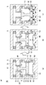
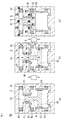
- FIGS. 13A to 13D are schematic diagrams showing the opening operation of the electromagnetic operation unit 250 of the switch.
- the switch according to the present embodiment is different from the switch 100 according to the first embodiment in the configuration of the fixed iron core 205.
- the movable iron core 6 starts moving in the opening direction from the closed position shown in FIG. 13 (a), and stops moving at the open position shown in FIG. 13 (e).
- the black arrow indicates the magnetic flux generated by the permanent magnet 2M1
- the white arrow indicates the magnetic flux generated by excitation of the opening coil 92.
- the fixed iron core 205 is a convex portion 251t (first convex portion) that protrudes inwardly in the opening / closing direction to the closed side of the inner end portions of the fixed first flange portion 251 and the fixed second flange portion 252 of the fixed iron core 205. And a convex portion 252t (second convex portion). Magnetic field shielding iron plates 2F1 and 2F2 are provided on the opening side of the convex portions 251t and 252t so as to be flush with the inner wall surfaces of the convex portions 251t and 252t.
- a non-magnetic eddy current induction copper plate D1 (first eddy current induction member) electrically connected to the magnetic field shielding iron plate 2F1 is flush with the magnetic field shielding iron plate 2F1 on the open side of the magnetic field shielding iron plate 2F1.
- a non-magnetic eddy current induction copper plate D2 (second eddy current induction member) electrically connected to the magnetic field shielding iron plate 2F2 is flush with the magnetic field shielding iron plate 2F2 on the open side of the magnetic field shielding iron plate 2F2.
- the magnetic flux that contributes to the electromagnetic force in the opening direction that occurs at the beginning of the opening operation of the movable core 6 passes through the convex portions 251t and 252t of the fixed core 205.
- the electromagnetic force acting in the opening direction at the beginning of the opening operation can be increased as compared with the first embodiment.
- the load of the opening spring or the contact pressure spring can be reduced, and the attractive force of the permanent magnet 2M1 necessary for holding the closed position can be reduced.
- 2M1 can be reduced in size, and the cost of the switch can be reduced.
- the braking force required to stop at the opening position can also be reduced, so that the magnetic field shielding iron plates 2F1 and 2F2 and the opening coil 92 can be downsized. it can.
- the movable first flange portion 61 and the movable second flange portion 62 are located at a position as shown in FIG. 13C, the magnetic flux is influenced by the eddy current, and the magnetic flux is fixed to the fixed first flange portion 251 of the fixed iron core 205. It is easy to concentrate on the flange portion 252.
- the electromagnetic force acting in the closing direction can be increased by increasing the closing direction component of the magnetic flux passing through these portions, so that the braking force generated by the eddy current is compensated. Is possible.
- the switch according to the second embodiment of the present invention it is possible to increase the electromagnetic force acting on the movable iron core 6 in the opening direction at the beginning of the opening operation. Further, the braking force acting on the movable iron core 6 can be supplemented near the opening position.
- FIGS. 14A to 14C are schematic views showing the opening operation of the switch 300.
- FIG. FIG. 14A shows a closed state
- FIG. 14B shows a driving state
- FIG. 14C shows an opened state.
- the switches according to the first embodiment and the second embodiment can maintain the closed state, the opened state, and the disconnected state at the three positions of the closed position, the opened position, and the disconnected position.
- the switch 300 is capable of switching and holding the state at two positions of the closing position and the opening position.
- the method for holding the closed state is the same as that of the switch 100 described in the first embodiment.
- the movable iron core 6 is fixed to the open position holding portion 354 on the open side of the fixed core 305 by the load of the open spring S2, so that the permanent magnet M2 is unnecessary.
- the operation method is not shown, it is the same as the opening operation and the closing operation described in the first embodiment.
- the opening position holding unit 354 may use resin or the like as long as it functions as a stopper.
- the opening operation with low impact can be performed by using the braking force due to the eddy current generated in the magnetic shielding plates F1 and F2.
- the closing operation becomes possible. Thereby, it is possible to provide the highly reliable switch 300 with a small number of parts.
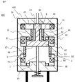
- FIG. 15 is an enlarged schematic cross-sectional view of the main part of the electromagnetic operation unit 450.
- the fixed iron core 405 is divided into two iron cores, a first fixed iron core 5a and a second fixed iron core 5b.
- the switch 100 of the first embodiment in the unlikely event that the movable iron core 6 overtravels during the opening operation, the movable iron core 6 is moved to the disconnection position holding portion 54 side of the fixed iron core 5 by the magnetic flux of the opening coil 92. Electromagnetic force to attract is also generated.
- the fixed iron core 405 is divided into two iron cores, that is, the first fixed iron core 5a and the second fixed iron core 5b, and a gap G is provided in the divided portion to increase the magnetic resistance, thereby suppressing the electromagnetic force that becomes the above-mentioned inhibiting factor.
- the division location is the disconnection side of the fixed second flange portion 52. In place of the gap G, a nonmagnetic material may be sandwiched.
Landscapes
- Physics & Mathematics (AREA)
- Electromagnetism (AREA)
- Engineering & Computer Science (AREA)
- Power Engineering (AREA)
- Driving Mechanisms And Operating Circuits Of Arc-Extinguishing High-Tension Switches (AREA)
- Electromagnets (AREA)
Abstract
Selon l'invention, dans un noyau fixe (5) d'un interrupteur (100) : un premier élément de blindage contre un champ magnétique (F1), comprenant un conducteur magnétique, est disposé au niveau de l'extrémité intérieure d'une première partie bride fixe (51) ; un second élément de blindage contre un champ magnétique (F2), comprenant un conducteur magnétique, est disposé au niveau de l'extrémité intérieure d'une seconde partie bride fixe (52) ; un premier élément de guidage de courants de Foucault (D1) comprenant un conducteur non magnétique, électriquement connecté au premier élément de blindage contre un champ magnétique (F1), est disposé au niveau de l'extrémité intérieure de la première partie bride fixe (51) dans le sens ouvert et/ou le sens fermé du premier élément de blindage contre un champ magnétique (F1) ; un second élément de guidage de courants de Foucault (D2) comprenant un conducteur non magnétique, électriquement connecté au second élément de blindage contre un champ magnétique (F2), est disposé au niveau de l'extrémité intérieure de la seconde partie bride fixe (52) dans le sens ouvert et/ou le sens fermé du second élément de blindage contre un champ magnétique (F2).
Priority Applications (1)
| Application Number | Priority Date | Filing Date | Title |
|---|---|---|---|
| JP2017517828A JP6301013B2 (ja) | 2015-05-13 | 2016-04-07 | 開閉器 |
Applications Claiming Priority (2)
| Application Number | Priority Date | Filing Date | Title |
|---|---|---|---|
| JP2015-098158 | 2015-05-13 | ||
| JP2015098158 | 2015-05-13 |
Publications (1)
| Publication Number | Publication Date |
|---|---|
| WO2016181732A1 true WO2016181732A1 (fr) | 2016-11-17 |
Family
ID=57248013
Family Applications (1)
| Application Number | Title | Priority Date | Filing Date |
|---|---|---|---|
| PCT/JP2016/061373 Ceased WO2016181732A1 (fr) | 2015-05-13 | 2016-04-07 | Interrupteur |
Country Status (2)
| Country | Link |
|---|---|
| JP (1) | JP6301013B2 (fr) |
| WO (1) | WO2016181732A1 (fr) |
Cited By (5)
| Publication number | Priority date | Publication date | Assignee | Title |
|---|---|---|---|---|
| KR101822416B1 (ko) * | 2017-06-30 | 2018-01-29 | 인텍전기전자 주식회사 | 차단기 |
| JP6771115B1 (ja) * | 2019-07-31 | 2020-10-21 | 三菱電機株式会社 | 開閉器 |
| CN112185764A (zh) * | 2020-09-28 | 2021-01-05 | 武汉同力同为科技有限公司 | 一种开关装置 |
| JP2021034736A (ja) * | 2019-08-22 | 2021-03-01 | フスコ オートモーティブ ホールディングス エル・エル・シーHUSCO Automotive Holdings LLC | マルチステーブルソレノイドのためのシステム及び方法 |
| CN115547743A (zh) * | 2022-10-17 | 2022-12-30 | 福州大学 | 一种双向旋转式电磁操动机构 |
Families Citing this family (1)
| Publication number | Priority date | Publication date | Assignee | Title |
|---|---|---|---|---|
| CN121331700A (zh) * | 2024-07-10 | 2026-01-13 | Abb瑞士股份有限公司 | 用于开关设备中的断路器的致动器 |
Citations (4)
| Publication number | Priority date | Publication date | Assignee | Title |
|---|---|---|---|---|
| JPH1172179A (ja) * | 1997-03-25 | 1999-03-16 | Toshiba Corp | しゃ断器の操作装置 |
| JP2002008498A (ja) * | 2000-06-26 | 2002-01-11 | Toshiba Corp | 遮断装置及び電磁アクチュエータ |
| JP2006302681A (ja) * | 2005-04-21 | 2006-11-02 | Mitsubishi Electric Corp | 電磁操作機構 |
| JP2013182752A (ja) * | 2012-03-01 | 2013-09-12 | Mitsubishi Electric Corp | 電磁操作装置 |
-
2016
- 2016-04-07 WO PCT/JP2016/061373 patent/WO2016181732A1/fr not_active Ceased
- 2016-04-07 JP JP2017517828A patent/JP6301013B2/ja active Active
Patent Citations (4)
| Publication number | Priority date | Publication date | Assignee | Title |
|---|---|---|---|---|
| JPH1172179A (ja) * | 1997-03-25 | 1999-03-16 | Toshiba Corp | しゃ断器の操作装置 |
| JP2002008498A (ja) * | 2000-06-26 | 2002-01-11 | Toshiba Corp | 遮断装置及び電磁アクチュエータ |
| JP2006302681A (ja) * | 2005-04-21 | 2006-11-02 | Mitsubishi Electric Corp | 電磁操作機構 |
| JP2013182752A (ja) * | 2012-03-01 | 2013-09-12 | Mitsubishi Electric Corp | 電磁操作装置 |
Cited By (10)
| Publication number | Priority date | Publication date | Assignee | Title |
|---|---|---|---|---|
| KR101822416B1 (ko) * | 2017-06-30 | 2018-01-29 | 인텍전기전자 주식회사 | 차단기 |
| WO2019004515A1 (fr) * | 2017-06-30 | 2019-01-03 | 인텍전기전자 주식회사 | Disjoncteur |
| JP6771115B1 (ja) * | 2019-07-31 | 2020-10-21 | 三菱電機株式会社 | 開閉器 |
| WO2021019724A1 (fr) | 2019-07-31 | 2021-02-04 | 三菱電機株式会社 | Commutateur |
| US11955300B2 (en) | 2019-07-31 | 2024-04-09 | Mitsubishi Electric Corporation | Switch |
| JP2021034736A (ja) * | 2019-08-22 | 2021-03-01 | フスコ オートモーティブ ホールディングス エル・エル・シーHUSCO Automotive Holdings LLC | マルチステーブルソレノイドのためのシステム及び方法 |
| JP7795292B2 (ja) | 2019-08-22 | 2026-01-07 | フスコ オートモーティブ ホールディングス エル・エル・シー | マルチステーブルソレノイドのためのシステム及び方法 |
| CN112185764A (zh) * | 2020-09-28 | 2021-01-05 | 武汉同力同为科技有限公司 | 一种开关装置 |
| CN112185764B (zh) * | 2020-09-28 | 2024-02-23 | 武汉同力同为科技有限公司 | 一种开关装置 |
| CN115547743A (zh) * | 2022-10-17 | 2022-12-30 | 福州大学 | 一种双向旋转式电磁操动机构 |
Also Published As
| Publication number | Publication date |
|---|---|
| JP6301013B2 (ja) | 2018-03-28 |
| JPWO2016181732A1 (ja) | 2017-07-27 |
Similar Documents
| Publication | Publication Date | Title |
|---|---|---|
| JP6301013B2 (ja) | 開閉器 | |
| US20190341214A1 (en) | Electromagnetic relay | |
| AU2010332675B2 (en) | Electromagnetic actuator having magnetic coupling, and cutoff device comprising such actuator | |
| JP6300157B2 (ja) | 電磁継電器 | |
| JP5809443B2 (ja) | 接点機構及びこれを使用した電磁接触器 | |
| CN103650089B (zh) | 电磁操作装置以及使用了该装置的开闭装置 | |
| KR101024773B1 (ko) | 전자 선형 조작기 | |
| EP2204825B1 (fr) | Actionneur magnétique permanent monostable utilisant un noyau d'acier stratifié | |
| KR101631760B1 (ko) | 전자기 릴레이 | |
| JP2004146333A (ja) | 操作装置およびその操作装置を使用した開閉装置 | |
| CN104303251B (zh) | 线路保护开关 | |
| CN105556630A (zh) | 开关装置的操作机构 | |
| KR20140074916A (ko) | 접점 장치 및 이것을 사용한 전자 접촉기 | |
| JP2016143623A (ja) | 電磁継電器 | |
| US8237527B2 (en) | Bistable permanent magnetic actuator | |
| JP2024133029A (ja) | リレー接触子の磁気シールド構造およびリレー | |
| CN112400209A (zh) | 具有真空断续器和驱动装置的中压断路器以及用于操作中压断路器的方法 | |
| GB2289374A (en) | Electromagnetic actuators | |
| JP6778908B2 (ja) | 電磁継電器 | |
| JP5627475B2 (ja) | 開閉器の操作機構 | |
| JP2008204864A (ja) | 開閉器 | |
| JP2017208316A (ja) | 開閉器用電磁操作装置 | |
| JP2004227966A (ja) | 操作装置およびその操作装置を使用した開閉装置 | |
| CN105321777A (zh) | 具有降低的开关噪音的开关设备 | |
| EP2197012A1 (fr) | Électroaimant pour contacteur électrique |
Legal Events
| Date | Code | Title | Description |
|---|---|---|---|
| 121 | Ep: the epo has been informed by wipo that ep was designated in this application |
Ref document number: 16792457 Country of ref document: EP Kind code of ref document: A1 |
|
| ENP | Entry into the national phase |
Ref document number: 2017517828 Country of ref document: JP Kind code of ref document: A |
|
| NENP | Non-entry into the national phase |
Ref country code: DE |
|
| 122 | Ep: pct application non-entry in european phase |
Ref document number: 16792457 Country of ref document: EP Kind code of ref document: A1 |