WO2016182004A1 - Générateur de pression d'huile et moteur à crosse - Google Patents
Générateur de pression d'huile et moteur à crosse Download PDFInfo
- Publication number
- WO2016182004A1 WO2016182004A1 PCT/JP2016/064060 JP2016064060W WO2016182004A1 WO 2016182004 A1 WO2016182004 A1 WO 2016182004A1 JP 2016064060 W JP2016064060 W JP 2016064060W WO 2016182004 A1 WO2016182004 A1 WO 2016182004A1
- Authority
- WO
- WIPO (PCT)
- Prior art keywords
- plunger
- main body
- hydraulic
- crosshead
- body member
- Prior art date
- Legal status (The legal status is an assumption and is not a legal conclusion. Google has not performed a legal analysis and makes no representation as to the accuracy of the status listed.)
- Ceased
Links
Images




Classifications
-
- F—MECHANICAL ENGINEERING; LIGHTING; HEATING; WEAPONS; BLASTING
- F02—COMBUSTION ENGINES; HOT-GAS OR COMBUSTION-PRODUCT ENGINE PLANTS
- F02B—INTERNAL-COMBUSTION PISTON ENGINES; COMBUSTION ENGINES IN GENERAL
- F02B75/00—Other engines
- F02B75/32—Engines characterised by connections between pistons and main shafts and not specific to preceding main groups
-
- F—MECHANICAL ENGINEERING; LIGHTING; HEATING; WEAPONS; BLASTING
- F02—COMBUSTION ENGINES; HOT-GAS OR COMBUSTION-PRODUCT ENGINE PLANTS
- F02B—INTERNAL-COMBUSTION PISTON ENGINES; COMBUSTION ENGINES IN GENERAL
- F02B75/00—Other engines
- F02B75/04—Engines with variable distances between pistons at top dead-centre positions and cylinder heads
- F02B75/044—Engines with variable distances between pistons at top dead-centre positions and cylinder heads by means of an adjustable piston length
-
- F—MECHANICAL ENGINEERING; LIGHTING; HEATING; WEAPONS; BLASTING
- F02—COMBUSTION ENGINES; HOT-GAS OR COMBUSTION-PRODUCT ENGINE PLANTS
- F02B—INTERNAL-COMBUSTION PISTON ENGINES; COMBUSTION ENGINES IN GENERAL
- F02B25/00—Engines characterised by using fresh charge for scavenging cylinders
- F02B25/02—Engines characterised by using fresh charge for scavenging cylinders using unidirectional scavenging
- F02B25/04—Engines having ports both in cylinder head and in cylinder wall near bottom of piston stroke
-
- F—MECHANICAL ENGINEERING; LIGHTING; HEATING; WEAPONS; BLASTING
- F02—COMBUSTION ENGINES; HOT-GAS OR COMBUSTION-PRODUCT ENGINE PLANTS
- F02B—INTERNAL-COMBUSTION PISTON ENGINES; COMBUSTION ENGINES IN GENERAL
- F02B75/00—Other engines
- F02B75/04—Engines with variable distances between pistons at top dead-centre positions and cylinder heads
-
- F—MECHANICAL ENGINEERING; LIGHTING; HEATING; WEAPONS; BLASTING
- F02—COMBUSTION ENGINES; HOT-GAS OR COMBUSTION-PRODUCT ENGINE PLANTS
- F02D—CONTROLLING COMBUSTION ENGINES
- F02D15/00—Varying compression ratio
- F02D15/02—Varying compression ratio by alteration or displacement of piston stroke
-
- F—MECHANICAL ENGINEERING; LIGHTING; HEATING; WEAPONS; BLASTING
- F04—POSITIVE - DISPLACEMENT MACHINES FOR LIQUIDS; PUMPS FOR LIQUIDS OR ELASTIC FLUIDS
- F04B—POSITIVE-DISPLACEMENT MACHINES FOR LIQUIDS; PUMPS
- F04B17/00—Pumps characterised by combination with, or adaptation to, specific driving engines or motors
- F04B17/05—Pumps characterised by combination with, or adaptation to, specific driving engines or motors driven by internal-combustion engines
-
- F—MECHANICAL ENGINEERING; LIGHTING; HEATING; WEAPONS; BLASTING
- F04—POSITIVE - DISPLACEMENT MACHINES FOR LIQUIDS; PUMPS FOR LIQUIDS OR ELASTIC FLUIDS
- F04B—POSITIVE-DISPLACEMENT MACHINES FOR LIQUIDS; PUMPS
- F04B3/00—Machines or pumps with pistons coacting within one cylinder, e.g. multi-stage
-
- F—MECHANICAL ENGINEERING; LIGHTING; HEATING; WEAPONS; BLASTING
- F04—POSITIVE - DISPLACEMENT MACHINES FOR LIQUIDS; PUMPS FOR LIQUIDS OR ELASTIC FLUIDS
- F04B—POSITIVE-DISPLACEMENT MACHINES FOR LIQUIDS; PUMPS
- F04B9/00—Piston machines or pumps characterised by the driving or driven means to or from their working members
- F04B9/02—Piston machines or pumps characterised by the driving or driven means to or from their working members the means being mechanical
- F04B9/025—Driving of pistons coacting within one cylinder
-
- F—MECHANICAL ENGINEERING; LIGHTING; HEATING; WEAPONS; BLASTING
- F16—ENGINEERING ELEMENTS AND UNITS; GENERAL MEASURES FOR PRODUCING AND MAINTAINING EFFECTIVE FUNCTIONING OF MACHINES OR INSTALLATIONS; THERMAL INSULATION IN GENERAL
- F16C—SHAFTS; FLEXIBLE SHAFTS; ELEMENTS OR CRANKSHAFT MECHANISMS; ROTARY BODIES OTHER THAN GEARING ELEMENTS; BEARINGS
- F16C5/00—Crossheads; Constructions of connecting-rod heads or piston-rod connections rigid with crossheads
-
- F—MECHANICAL ENGINEERING; LIGHTING; HEATING; WEAPONS; BLASTING
- F16—ENGINEERING ELEMENTS AND UNITS; GENERAL MEASURES FOR PRODUCING AND MAINTAINING EFFECTIVE FUNCTIONING OF MACHINES OR INSTALLATIONS; THERMAL INSULATION IN GENERAL
- F16C—SHAFTS; FLEXIBLE SHAFTS; ELEMENTS OR CRANKSHAFT MECHANISMS; ROTARY BODIES OTHER THAN GEARING ELEMENTS; BEARINGS
- F16C2360/00—Engines or pumps
- F16C2360/22—Internal combustion engines
Definitions
- the present disclosure relates to a hydraulic generator for a crosshead engine in which a crosshead is fixed to a piston rod, and a crosshead engine.
- This application claims priority based on Japanese Patent Application No. 2015-96717 for which it applied to Japan on May 11, 2015, and uses the content here.
- a crosshead In a crosshead type engine that is widely used in marine engines, a crosshead is provided at an end of a piston rod to which a piston is fixed.
- the connecting rod connects the crosshead and the crankshaft, and the reciprocating motion of the crosshead is converted into the rotational motion of the crankshaft.
- the engine of Patent Document 1 is such a crosshead type engine, in which a hydraulic piston is arranged in the crosshead, and the hydraulic piston is operated by hydraulic pressure, so that the position of the top dead center of the piston is changed and compressed.
- the ratio is variable.
- the present disclosure provides a hydraulic generator for a crosshead engine that does not require installation of a new hydraulic pump, or enables a newly installed hydraulic pump to have a small output, and a crosshead. It aims to provide a type engine.
- a hydraulic pressure generator for a crosshead type engine includes a first end of a piston rod to which a piston is fixed, and a connecting rod connected to a crankshaft.
- This is a hydraulic generator for a crosshead engine in which the second end is connected via a crosshead and the crosshead reciprocates in the piston stroke direction, and reciprocates integrally with the piston and crosshead in the piston stroke direction.
- a pressure boosting chamber that pressurizes oil and discharges it from the discharge port; a distal end is located outside the main body member; a proximal end faces the pressure increasing chamber inside the main body member; and the piston A plunger that slides in a direction that intersects the stroke direction, and is spaced apart from the main body member in the sliding direction of the plunger, the separation distance from the main body member being a first distance, and the plunger toward the boosting chamber side
- the first pressing portion where the pressing amount becomes the first pressing amount, and the first pressing portion and the position in the stroke direction are different, and the separation distance from the main body member is a second distance smaller than the first distance, In the process of moving the plunger from the first pressing portion to the second pressing portion, the second pressing portion having a second pressing amount that is larger than the first pressing amount.
- a crosshead engine of the present disclosure includes the above-described hydraulic pressure generator.
- the engine it is possible to selectively execute any one of a gas operation mode in which fuel gas that is gaseous fuel is mainly burned and a diesel operation mode in which fuel oil that is liquid fuel is burned.
- a so-called dual fuel type engine will be described. Further, a description will be given of a case where the engine completes one cycle in two strokes (two-cycle engine, two-stroke engine) and is a uniflow scavenging type in which gas flows in one direction inside the cylinder.
- the type of engine is not limited to the dual fuel type, the two-cycle type, and the uniflow scavenging type, and may be a crosshead type engine.
- FIG. 1 is a diagram illustrating the overall configuration of a uniflow scavenging two-cycle engine 100 (crosshead engine).
- the uniflow scavenging two-cycle engine 100 of the present embodiment is used for, for example, ships.
- the uniflow scavenging two-cycle engine 100 includes a cylinder 110, a piston 112, a crosshead 114, a connecting rod 116, a crankshaft 118, an exhaust port 120, an exhaust valve 122, and a scavenging port 124.
- the scavenging reservoir 126, the cooler 128, the scavenging chamber 130, and the combustion chamber 132 are configured.
- the piston 112 has an upper end fixed to the piston rod 112a.
- the lower end (first end) of the piston rod 112 a is connected to a cross head pin 114a in the cross head 114, and the cross head 114 reciprocates together with the piston 112.
- the cross head 114 is restricted from moving in the direction perpendicular to the stroke direction of the piston 112 (left and right direction in FIG. 1) by the cross head shoe 114b.
- the cross head pin 114 a is inserted through a hole provided at the upper end (second end) of the connecting rod 116 and supports the second end of the connecting rod 116.
- the lower end of the connecting rod 116 is connected to the crankshaft 118 so that the crankshaft 118 rotates with respect to the connecting rod 116.
- the first end of the piston rod 112a to which the piston 112 is fixed and the second end of the connecting rod 116 connected to the crankshaft 118 are connected via the cross head 114, and the cross head 114 is connected to the stroke of the piston 112. Move back and forth in the direction.
- the exhaust port 120 is an opening provided in the cylinder head 110 a above the top dead center of the piston 112, and is opened and closed to exhaust the exhaust gas after combustion generated in the cylinder 110.
- the exhaust valve 122 is moved up and down at a predetermined timing by an unillustrated exhaust valve driving device to open and close the exhaust port 120.
- the exhaust gas exhausted through the exhaust port 120 in this way is supplied to the turbine side of the supercharger C through the exhaust pipe 120a and then exhausted to the outside.
- the scavenging port 124 is a hole penetrating from the inner peripheral surface on the lower end side of the cylinder 110 (the inner peripheral surface of the cylinder liner 110 b) to the outer peripheral surface, and a plurality of scavenging ports 124 are provided over the entire periphery of the cylinder 110.
- the scavenging port 124 sucks the active gas into the cylinder 110 according to the sliding motion of the piston 112.
- This active gas contains an oxidizing agent such as oxygen and ozone, or a mixture thereof (for example, air).
- the scavenging reservoir 126 is filled with active gas (for example, air) pressurized by the compressor of the supercharger C, and the active gas is cooled by the cooler 128.
- active gas for example, air
- the cooled active gas is pressed into a scavenging chamber 130 formed in the cylinder jacket 110c.
- the active gas is sucked into the cylinder 110 from the scavenging port 124 due to the differential pressure between the scavenging chamber 130 and the cylinder 110.
- the cylinder head 110a is provided with a liquid fuel injection valve 134.
- a liquid fuel injection valve 134 In the gas operation mode, an appropriate amount of fuel oil is injected from the liquid fuel injection valve 134 at a desired point in the engine cycle.
- the fuel oil is vaporized by the heat of the combustion chamber 132 surrounded by the cylinder head 110a, the cylinder liner 110b, and the piston 112, and is spontaneously ignited and burns in a short time, so that the temperature of the combustion chamber 132 is extremely reduced. Make it high.
- a gas fuel injection valve (not shown) is provided in the vicinity of the scavenging port 124 or in a portion of the cylinder 110 from the scavenging port 124 to the combustion chamber 132, and is injected from the gaseous fuel injection valve and flows into the cylinder 110.
- the fuel gas is reliably burned at a desired timing by being heated by the combustion heat of the fuel oil.
- the piston 112 reciprocates mainly by the expansion pressure due to the combustion of fuel gas.
- the fuel gas is generated, for example, by gasifying LNG (liquefied natural gas).
- LNG liquefied natural gas
- the fuel gas is not limited to LNG, and for example, LPG (liquefied petroleum gas), light oil, heavy oil, etc. can be gasified and applied.
- the uniflow scavenging two-cycle engine 100 selectively executes one of the gas operation mode and the diesel operation mode.
- the uniflow scavenging two-cycle engine 100 is provided with a variable mechanism.
- the variable mechanism will be described in detail.
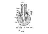
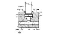
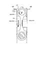
- FIG. 2A and 2B are diagrams for explaining a connecting portion between the piston rod 112a and the cross head pin 114a.
- FIG. 2A shows an enlarged view in which a portion surrounded by an alternate long and short dash line in FIG. 1 is extracted, and
- FIG. 2A shows a cross section taken along line II (b) -II (b) in FIG. 2A.
- the first end of the piston rod 112a is inserted into the crosshead pin 114a.
- the cross head pin 114a is formed with a connection hole 160 extending perpendicularly to the axial direction of the cross head pin 114a (the left-right direction in FIG. 2B).
- the connection hole 160 is a hydraulic chamber, and the first end of the piston rod 112a is inserted into the hydraulic chamber.
- the first end of the piston rod 112a is inserted into the connection hole 160, whereby the cross head pin 114a and the piston rod 112a are connected.
- the piston rod 112a has a large-diameter portion 162a in which the outer diameter of the piston rod 112a is larger than that of the first end side, and is positioned on the first end side of the large-diameter portion 162a.
- a small-diameter portion 162b having a smaller outer diameter is formed.
- the connecting hole 160 is continuous to the connecting rod 116 side with respect to the large-diameter hole 164a located on the piston 112 side in the connecting hole 160 and the large-diameter hole 164a, and has an inner diameter smaller than that of the large-diameter hole 164a. And a small-diameter hole 164b.
- the small diameter portion 162b of the piston rod 112a can be inserted into the small diameter hole portion 164b of the connection hole 160, and the large diameter portion 162a of the piston rod 112a is set to a size that can be inserted into the large diameter hole portion 164a of the connection hole 160.
- the inner peripheral surface of the small-diameter hole portion 164b, the first seal member O 1 constituted by O-ring is described.
- a fixed lid 166 having an outer diameter larger than that of the connection hole 160 is fixed to the upper end (second end) side of the piston rod 112a from the large diameter portion 162a of the piston rod 112a.
- the fixed lid 166 is an annular member, and the piston rod 112a is inserted from above.
- the inner peripheral surface of the fixed cover 166 of the piston rod 112a is inserted, the second sealing member O 2 is arranged constituted by an O-ring.
- a recess 114c that is recessed in the radial direction of the crosshead pin 114a is formed on the outer peripheral surface of the crosshead pin 114a, and a fixed lid 166 is fitted inside the recess 114c.
- a first hydraulic chamber 168a (hydraulic chamber) and a second hydraulic chamber 168b (hydraulic chamber) are formed inside the cross head pin 114a at the connecting portion between the piston rod 112a and the cross head pin 114a.
- the first hydraulic chamber 168a includes a step surface due to a difference in outer diameter between the large diameter portion 162a and the small diameter portion 162b, an inner peripheral surface of the large diameter hole portion 164a, and a step due to a difference in inner diameter between the large diameter hole portion 164a and the small diameter hole portion 164b. Surrounded by a face.
- the second hydraulic chamber 168b is surrounded by the end surface on the upper end side of the piston rod 112a, the inner peripheral surface of the large diameter hole 164a, and the rotation lid 166 in the large diameter portion 162a. That is, the large diameter portion 162a of the piston rod 112a divides the large diameter hole portion 164a into the first end side of the piston rod 112a and the second end side of the connecting rod 116. Then, the first hydraulic chamber 168a is formed by the large-diameter hole 164a defined below the large-diameter portion 162a with the large-diameter portion 162a as a boundary, and the large-diameter portion 164a defined above the large-diameter portion 162a. A second hydraulic chamber 168b is formed by the diameter hole portion 164a.
- a supply oil passage 170a and a drain oil passage 170b communicate with the first hydraulic chamber 168a.
- the supply oil passage 170a has an upper end (second end) that opens to a stepped surface due to an inner diameter difference between the large-diameter hole 164a and the small-diameter hole 164b, and a lower end (first end) that communicates with a later-described hydraulic pressure generator.
- the oil drainage path 170b communicates with a solenoid valve (not shown), and an upper end (second end) opens to a stepped surface due to a difference in inner diameter between the large diameter hole 164a and the small diameter hole 164b.
- An auxiliary oil passage 170c that opens to the wall surface of the fixed lid 166 communicates with the second hydraulic chamber 168b.
- the auxiliary oil passage 170c passes through the inside of the cross head pin 114a via a contact portion between the fixed lid 166 and the cross head pin 114a, and communicates with a hydraulic pump (not shown).
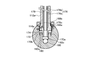
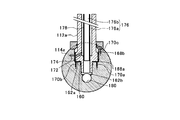
- FIG. 3A and 3B are diagrams for explaining changes in the relative positions of the piston rod 112a and the crosshead pin 114a.
- FIG. 3A shows a state in which the piston rod 112a has entered the connection hole 160 shallowly
- FIG. A state in which the piston rod 112a has entered the connection hole 160 deeply is shown.
- the first hydraulic chamber 168a has a variable length in the stroke direction of the piston 112.
- the inertial force of the piston rod 112a may be large, and the piston rod 112a may move too much to the piston 112 side.
- the hydraulic pressure from the hydraulic pump is applied to the second hydraulic chamber 168b via the auxiliary oil passage 170c to suppress such movement of the piston rod 112a. Yes.
- the uniflow scavenging two-cycle engine 100 is used at a relatively low rotational speed, the inertial force of the piston rod 112a is small, and even if the hydraulic pressure supplied to the second hydraulic chamber 168b is low, the top dead center position can be obtained. Deviation can be suppressed.
- the piston rod 112a is provided with a flow path hole 172 that extends radially inward from the outer peripheral surface of the piston rod 112a.
- the cross head pin 114a is provided with a through hole 174 that penetrates from the outer peripheral surface side of the cross head pin 114a to the connection hole 160.
- the through hole 174 communicates with the hydraulic pump described above.
- the flow path hole 172 and the through hole 174 are opposed to each other in the radial direction of the piston rod 112a, and the flow path hole 172 and the through hole 174 communicate with each other.
- the end of the flow path hole 172 on the outer peripheral surface side is formed wider than the other part of the flow path hole 172 in the stroke direction of the piston 112 (vertical direction in FIGS. 3A and 3B). As shown in FIGS. 3A and 3B, even if the relative positions of the piston rod 112a and the cross head pin 114a change, the communication state of the flow path hole 172 and the through hole 174 is maintained.
- a third seal member O 3 composed of an O-ring is formed so that the end on the outer peripheral surface side of the flow path hole 172 is sandwiched from above and below along the axial direction of the piston rod 112a. 4 the sealing member O 4 is disposed (see FIG. 2A and B).
- the large-diameter portion 162a has a smaller area facing the inner peripheral surface of the large-diameter hole 164a by the amount corresponding to the flow path hole 172, and is easily inclined with respect to the large-diameter hole 164a.
- the small-diameter portion 162b is guided by the small-diameter hole portion 164b, so that the inclination of the piston rod 112a with respect to the stroke direction is suppressed.
- a cooling oil passage 176 that extends in the stroke direction of the piston 112 and through which cooling oil for cooling the piston 112 and the piston rod 112a flows is formed inside the piston rod 112a.
- a cooling pipe 178 is arranged inside the cooling oil path 176, and the cooling oil path 176 is divided by the cooling pipe 178 into a forward path 176a on the radially outer side of the piston rod 112a and an inner return path 176b.
- the flow path hole 172 opens in the forward path 176 a of the cooling oil path 176.
- the cooling oil supplied from the hydraulic pump flows into the forward path 176 a of the cooling oil path 176 through the through hole 174 and the flow path hole 172.
- the forward path 176a and the return path 176b communicate with each other inside the piston 112, and the cooling oil that has flowed through the forward path 176a returns to the small diameter portion 162b side through the return path 176b when reaching the inner wall of the piston 112.
- the piston 112 is cooled by the cooling oil coming into contact with the inner wall of the cooling oil passage 176 and the inner wall of the piston 112.
- the cross head pin 114 a is formed with an outlet hole 180 extending in the axial direction of the cross head pin 114 a, and the small diameter hole portion 164 b communicates with the outlet hole 180.
- the cooling oil that has flowed into the small-diameter hole 164b from the cooling oil passage 176 is discharged out of the crosshead pin 114 ⁇ a through the outlet hole 180, and circulates to the tank.
- the hydraulic oil supplied to the first hydraulic chamber 168a and the second hydraulic chamber 168b and the cooling oil supplied to the cooling oil passage 176 are both circulated to the same tank and boosted by the same hydraulic pump. For this reason, it is possible to perform the supply of hydraulic oil for applying hydraulic pressure and the supply of cooling oil for cooling with a single hydraulic pump, thereby reducing the cost.
- FIG. 4 is a diagram for explaining the arrangement of the hydraulic pressure generator 200.
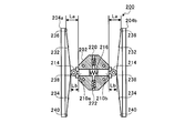
- the hydraulic pressure generator 200 includes a main body member 202 and a pair of plunger pressing members 204 a and 204 b.
- the main body member 202 is fixed to one end surface 114d of the cross head pin 114a.
- the main body member 202 reciprocates integrally with the piston 112 and the cross head 114 in the stroke direction of the piston 112.
- the position of the cross head pin 114a in the axial direction is located on the front side in FIG. 4 with respect to the connecting rod 116, and is fixed to the frame 206, respectively.
- the main body member 202 and the plunger pressing members 204a and 204b are arranged so that the axial positions of the cross head pins 114a overlap each other.
- the body member 202 reciprocates together with the piston 112 and the cross head 114, the body member 202 passes between the pair of plunger pressing members 204a and 204b.
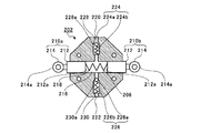
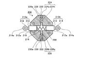
- FIGS. 5A and 5B are diagrams illustrating the main body member 202, and a schematic cross-sectional view of the main body member 202 is shown.
- the main body member 202 is formed with a through-hole 208 that penetrates in the left-right direction in FIGS. 5A and 5B, and a pair of plungers 210a and 210b are inserted through the through-hole 208. .
- Each of the plungers 210a and 210b has a plunger main body 212 and a roller 214.
- the plunger body 212 is inserted into the through hole 208 and has a tip protruding from the through hole 208.
- the rollers 214 are provided at the tip of the plunger body 212 protruding from the through hole 208, respectively. 5A and 5B, the roller 214 is rotatable with the direction perpendicular to the paper surface as the rotation axis direction.
- the tips of the plungers 210 a and 210 b are located outside the main body member 202.
- the base ends of the plungers 210 a and 210 b are located inside the through hole 208 of the main body member 202.
- the base end portions 212 a of the plunger main body 212 of the plungers 210 a and 210 b are spaced apart from each other, and the pressure increasing chamber 216 is formed by the base end portion 212 a of the plunger main body 212 and the inner wall of the through hole 208.
- the base end portions 212 a of the plunger main bodies 212 of the plungers 210 a and 210 b face the pressurizing chamber 216 inside the main body member 202.
- the plungers 210 a and 210 b slide in the through hole 208.
- the stroke direction of the piston 112 is the vertical direction
- the plungers 210a and 210b slide in a direction intersecting the stroke direction of the piston 112 (here, a direction perpendicular to the stroke direction of the piston 112). To do.
- the pair of plungers 210a and 210b are provided so as to be spaced apart from each other in the sliding direction across the boosting chamber 216, and in the boosting chamber 216, the pair of plungers 210a and 210b are separated from each other.
- An elastic member 218 for applying a biasing force is provided. Both ends of the elastic member 218 are fixed to base end portions 212a of the plunger main bodies 212 of the plungers 210a and 210b, respectively.
- the introduction port 220 is provided on the upper side of the main body member 202, and the discharge port 222 is provided on the lower side.
- the introduction port 220 is connected to a hydraulic oil supply source, for example, a hydraulic oil tank, and the hydraulic oil is guided from the hydraulic oil tank.
- the discharge port 222 communicates with the first hydraulic chamber 168a via the above-described supply oil passage 170a.
- the main body member 202 is provided with a first communication passage 228 that communicates from the introduction port 220 to the pressure increasing chamber 216.
- the first communication passage 228 is formed with a taper 228a having a smaller inner diameter toward the introduction port 220, and a first check valve 224 is provided closer to the pressure increasing chamber 216 than the taper 228a.
- the first check valve 224 includes a spherical valve body 224a and an elastic spring 224b, and the valve body 224a is biased upward in FIGS. 5A and 5B by the elastic spring 224b.
- the valve body 224a comes into contact with the taper 228a in the first communication passage 228 and causes the first communication passage 228 to enter. close.
- the first check valve 224 suppresses the flow of hydraulic oil from the pressure increasing chamber 216 to the introduction port 220.
- the main body member 202 is provided with a second communication passage 230 that communicates from the pressure increasing chamber 216 to the discharge port 222.
- the second communication passage 230 is formed with a taper 230a whose inner diameter increases toward the discharge port 222, and a second check valve 226 is provided closer to the discharge port 222 than the taper 230a.
- the second check valve 226 includes a spherical valve body 226a and an elastic spring 226b, and the valve body 226a is biased upward in FIGS. 5A and 5B by the elastic spring 226b.
- the valve body 226 a contacts the taper 230 a in the second communication path 230 and closes the second communication path 230. In this way, the second check valve 226 suppresses the flow of hydraulic oil from the discharge port 222 to the pressure increasing chamber 216.
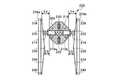
- FIG. 6A to 6C are diagrams for explaining the operation of the hydraulic pressure generator 200.
- FIG. 6A to 6C show a state in which the main body member 202 is moved to the plunger pressing members 204a and 204b side along the stroke direction of the piston 112, compared to the state shown in FIG.
- each of the plunger pressing members 204a and 204b has a first inclined surface 232 (an inclined surface) and a second inclined surface 234 (an inclined surface).
- the first inclined surface 232 is inclined in the direction in which the facing distance between the plunger pressing members 204a and 204b becomes narrower toward the lower side in the stroke direction (lower side in FIG. 6A).
- the 2nd inclined surface 234 inclines in the direction where the opposing space
- the first pressing portion 236 is the upper end portion of the first inclined surface 232 of the plunger pressing members 204a and 204b in FIG. 6A, and the sliding direction of the plungers 210a and 210b (the left-right direction in FIGS. 6A to 6C). ) Is separated from the main body member 202.
- the distance in the left-right direction between the first pressing portion 236 and the main body member 202 is defined as a first distance La.
- the pushing amount of the plungers 210a and 210b toward the boosting chamber 216 is set to a first pushing amount (here, 0).
- the 2nd press part 238 is a site
- the second pressing portion 238 is the second distance Lb in which the horizontal distance from the main body member 202 is smaller than the first distance La, and the facing distance between the plunger pressing members 204a and 204b is the smallest. It is a part.
- the pressing amount of the plungers 210a and 210b toward the boosting chamber 216 becomes a second pressing amount larger than the first pressing amount.
- the roller 214 is pressed by the plunger pressing members 204a and 204b while sliding on the first inclined surface 232, and the plungers 210a and 210b are moved to the first position.
- the pressure is pushed into the pressurizing chamber 216 by the amount pushed by two.
- the plunger pressing members 204a and 204b push the plungers 210a and 210b toward the pressure increasing chamber 216 in the process in which the plungers 210a and 210b move from the first pressing portion 236 to the second pressing portion 238.
- the pressurizing chamber 216 pressurizes the hydraulic oil guided from the introduction port 220 to the main body member 202 and discharges it from the discharge port 222.
- the hydraulic oil discharged from the discharge port 222 flows into the first hydraulic chamber 168a through the supply oil passage 170a, and the relative positions of the piston rod 112a and the cross head pin 114a change.
- the second inclined surface 234 is also the second inclined surface 234 when the main body member 202 moved downward from the second pressing portion 238 moves upward in FIG. 6A in the stroke direction. It operates in the same manner as the one inclined surface 232. That is, in FIG. 6A, the lower end portion of the second inclined surface 234 serves as the first pressing portion 240, and the plunger pressing members 204 a and 204 b have the plungers 210 a and 210 b that are separated from the first pressing portion 240. In the process of moving to the second pressing portion 238, the plungers 210a and 210b are pushed into the pressure increasing chamber 216 side.
- FIGS. 7A and 7B are diagrams for explaining the control of the hydraulic pressure generator 200.
- a swing mechanism 242 is provided on the plunger pressing member 204a side.
- the swing mechanism 242 includes a support portion 242a and an actuator 242b.
- the support portion 242a pivotally supports the lower end side in FIG. 7A of the plunger pressing member 204a.
- the plunger pressing member 204a can swing to the position shown in FIG. 7B with the fulcrum pivotally supported by the support portion 242a as the rotation axis center. Further, the support portion 242a biases the plunger pressing member 204a in the direction of rotating counterclockwise.
- the actuator 242b is, for example, a hydraulic type, and a roller 242c is provided at the tip. Then, the actuator 242b receives a pressing force by hydraulic pressure, and the tip portion moves in the left-right direction in FIG. 7A. The roller 242c comes into contact with the plunger pressing member 204a from the left side in FIG. 7A and presses the plunger pressing member 204a in the clockwise rotation direction.
- the plunger pressing members 204a and 204b are in the pressure increasing position where the pressure of the hydraulic oil in the pressure increasing chamber 216 can be increased.
- the actuator 242b is activated and the roller 242c moves to the left as shown in FIG. 7B
- the plunger pressing member 204a swings following the roller 242c by the urging force from the support portion 242a, and the plunger pressing member
- the separation distance between the second pressing portion 238 of 204a and the second pressing portion 238 of the plunger pressing member 204b is increased.
- the plunger pressing member 204a reduces the volume of the boosting chamber 216 shown in FIG. 7A, and boosts the hydraulic oil in the boosting chamber 216 shown in FIG. 7B from the boosting position where the hydraulic fluid can be boosted. Move to the retreat position where it becomes impossible. Therefore, the hydraulic pressure generator 200 can switch ON / OFF of hydraulic pressure generation with a simple configuration. When the hydraulic pressure is unnecessary, by setting the plunger pressing member 204a to the retracted position, it is possible to suppress fuel consumption without applying unnecessary resistance to the piston 112.
- produce can be adjusted by controlling the plunger press member 204a to the arbitrary positions from the pressure
- the hydraulic pressure can be generated by the hydraulic pressure generator 200, it is not necessary to install a new hydraulic pump for generating the hydraulic pressure in the crosshead engine. Alternatively, even if a hydraulic pump is installed, the installed hydraulic pump has a small output, and the hydraulic pressure generator 200 can boost the hydraulic oil to a high pressure by the power of the piston 112.
- the roller 214 contacts the plunger pressing members 204a and 204b from the direction intersecting the stroke direction of the piston 112. To do. Therefore, the impact at the time of contact is small, and it is possible to suppress the shock wave generated in the hydraulic oil. Further, the plunger pressing members 204a and 204b can be arranged at any position in the movement range along the stroke direction of the main body member 202, and the degree of freedom of installation is high.
- the hydraulic pressure generating device 200 generates the hydraulic pressure for changing the relative positions of the piston rod 112a and the cross head pin 114a has been described.
- the hydraulic pressure generated by the hydraulic pressure generating device 200 is not limited to this. You may use for the use.
- the main body member 202 is provided on the cross head 114 .
- the main body member 202 moves integrally with the piston 112 in the stroke direction of the piston 112
- the main body member is attached to a member other than the cross head 114. 202 may be provided.
- the main body member 202 is provided on the cross head 114, it can be easily arranged without interfering with other members.
- both the 1st inclined surface 232 and the 2nd inclined surface 234 are essential. Absent. However, by providing the first inclined surface 232 and the second inclined surface 234, the hydraulic pressure can be gradually increased. In addition, only one of the first inclined surface 232 and the second inclined surface 234 may be provided, but by providing both the first inclined surface 232 and the second inclined surface 234, 2 may be provided during one stroke. The hydraulic pressure can be increased, allowing for quick pressure increase.
- first inclined surface 232 and the second inclined surface 234 are illustrated as linear shapes, the first inclined surface 232 and the second inclined surface 234 are curved surfaces calculated so that the hydraulic pressure increase rate due to movement of the main body member 202 in the stroke direction does not change abruptly. There may be.
- the plunger pressing members 204a and 204b are operated from the boosting position to the retracted position.
- the plunger pressing members 204a and 204b are not operated, for example, the operation discharged from the discharge port 222.
- a switching valve or the like may be provided in the oil passage of oil to switch ON / OFF of pressure increase.
- the plungers 210a and 210b have been described as being provided with a pair of the pressure increasing chamber 216 spaced apart from each other in the sliding direction. However, only one of the plungers 210a and 210b is provided. Also good. However, when both the plungers 210a and 210b are provided, the elastic member 218 is provided in the pressure increasing chamber 216, and the plunger pressing members 204a and 204b are provided for the pair of plungers 210a and 210b, the following effects are obtained.
- the desired pressure increase performance is exhibited as long as the distance between the plunger pressing members 204a and 204b is not shifted. can do. That is, by providing a pair of plungers 210a and 210b, strict management of dimensions is not required, and design work and assembly work can be simplified.
- first check valve 224 and the second check valve 226 are provided in the main body member 202 .
- first check valve 224 and the second check valve 226 are provided.
- an electromagnetic valve or the like may be provided.
- the flow of the hydraulic oil is controlled with a simple configuration and high accuracy, and the hydraulic pressure in the boost chamber 216 is increased. It becomes possible to do.
- the present disclosure can be used for a crosshead type engine hydraulic pressure generator in which a crosshead is fixed to a piston rod, and a crosshead type engine.
Landscapes
- Engineering & Computer Science (AREA)
- General Engineering & Computer Science (AREA)
- Mechanical Engineering (AREA)
- Chemical & Material Sciences (AREA)
- Combustion & Propulsion (AREA)
- Output Control And Ontrol Of Special Type Engine (AREA)
- Reciprocating Pumps (AREA)
- Lubrication Of Internal Combustion Engines (AREA)
- Details Of Reciprocating Pumps (AREA)
Abstract
L'invention concerne un générateur de pression d'huile (200) d'un moteur à crosse, dans lequel dispositif le sommet est disposée sur la partie externe de l'élément principal, et la base fait face à une chambre de compression (216) à l'intérieur de l'élément principal (202). Le générateur de pression d'huile (200) comprend : des plongeurs (210a, 210b) qui coulissent dans une direction perpendiculaire à la direction de la course d'un piston; des premiers éléments de pression (236, 240) qui sont disposés à une certaine distance de l'élément principal dans la direction de coulissement des plongeurs, ladite distance de séparation par rapport à l'élément principal étant une première distance (La), et la quantité de poussée des plongeurs à l'intérieur de la partie latérale de la chambre de compression étant une première quantité de poussée; et des seconds éléments de presson (238), la distance de séparation par rapport à l'élément principal étant une seconde distance (Lb), et la quantité de poussée des plongeurs côté chambre d'amplification de pression étant une seconde quantité de poussée qui est supérieure à la première quantité de poussée. Le générateur de pression d'huile (200) comporte des éléments de pression des plongeurs (204a, 204b) qui poussent les plongeurs vers la partie latérale de la chambre de compression au cours du processus de déplacement des plongeurs des premiers éléments de pression vers les seconds éléments de pression.
Priority Applications (4)
| Application Number | Priority Date | Filing Date | Title |
|---|---|---|---|
| EP16792729.2A EP3296539B1 (fr) | 2015-05-11 | 2016-05-11 | Générateur de pression d'huile et moteur à crosse |
| KR1020177017261A KR101917340B1 (ko) | 2015-05-11 | 2016-05-11 | 유압 발생 장치 및 크로스헤드형 엔진 |
| DK16792729.2T DK3296539T3 (da) | 2015-05-11 | 2016-05-11 | Olietrykgenereringsindretning og krydshovedmotor |
| CN201680022603.9A CN107532509B (zh) | 2015-05-11 | 2016-05-11 | 油压产生装置及十字头型发动机 |
Applications Claiming Priority (2)
| Application Number | Priority Date | Filing Date | Title |
|---|---|---|---|
| JP2015096717A JP6451486B2 (ja) | 2015-05-11 | 2015-05-11 | 油圧発生装置およびクロスヘッド型エンジン |
| JP2015-096717 | 2015-05-11 |
Publications (1)
| Publication Number | Publication Date |
|---|---|
| WO2016182004A1 true WO2016182004A1 (fr) | 2016-11-17 |
Family
ID=57248968
Family Applications (1)
| Application Number | Title | Priority Date | Filing Date |
|---|---|---|---|
| PCT/JP2016/064060 Ceased WO2016182004A1 (fr) | 2015-05-11 | 2016-05-11 | Générateur de pression d'huile et moteur à crosse |
Country Status (6)
| Country | Link |
|---|---|
| EP (1) | EP3296539B1 (fr) |
| JP (1) | JP6451486B2 (fr) |
| KR (1) | KR101917340B1 (fr) |
| CN (1) | CN107532509B (fr) |
| DK (1) | DK3296539T3 (fr) |
| WO (1) | WO2016182004A1 (fr) |
Cited By (1)
| Publication number | Priority date | Publication date | Assignee | Title |
|---|---|---|---|---|
| WO2019239864A1 (fr) * | 2018-06-11 | 2019-12-19 | 株式会社Ihi | Mécanisme à taux de compression variable |
Families Citing this family (5)
| Publication number | Priority date | Publication date | Assignee | Title |
|---|---|---|---|---|
| JP6946977B2 (ja) * | 2017-11-28 | 2021-10-13 | 株式会社Ihi | 可変圧縮装置及びエンジンシステム |
| JP6866325B2 (ja) * | 2018-03-16 | 2021-04-28 | 株式会社Ihi原動機 | 舶用エンジン |
| JP2019157845A (ja) | 2018-03-16 | 2019-09-19 | 株式会社ディーゼルユナイテッド | 舶用エンジン |
| KR102387966B1 (ko) * | 2018-04-06 | 2022-04-18 | 가부시키가이샤 아이에이치아이 | 가변 압축 장치 및 엔진 시스템 |
| JP7214980B2 (ja) * | 2018-05-30 | 2023-01-31 | 株式会社Ihi | 圧縮比可変機構 |
Citations (7)
| Publication number | Priority date | Publication date | Assignee | Title |
|---|---|---|---|---|
| JPS62111179A (ja) * | 1985-11-08 | 1987-05-22 | Yoshimichi Yoshida | 船舶用ポンプ |
| DE19835146A1 (de) * | 1998-08-04 | 1999-06-10 | Daimler Chrysler Ag | Pleuelstange |
| JP2005054619A (ja) * | 2003-07-31 | 2005-03-03 | Honda Motor Co Ltd | 内燃機関の圧縮比可変装置 |
| US20090205615A1 (en) * | 2008-02-19 | 2009-08-20 | Tonand Brakes Inc. | Variable compression ratio system |
| US20100275884A1 (en) * | 2009-05-01 | 2010-11-04 | Gray Jr Charles L | Quasi Free Piston Engine |
| JP2014020375A (ja) * | 2012-07-17 | 2014-02-03 | Waertsilae Schweiz Ag | 大型往復ピストン燃焼エンジン、ならびにそのようなエンジンを制御する制御機器および方法 |
| JP2015503058A (ja) * | 2011-12-23 | 2015-01-29 | アー・ファウ・エル・リスト・ゲー・エム・ベー・ハーAvl Listgmbh | 往復ピストンエンジン用のコネクティングロッド |
Family Cites Families (4)
| Publication number | Priority date | Publication date | Assignee | Title |
|---|---|---|---|---|
| US1595452A (en) * | 1925-09-04 | 1926-08-10 | Cole Lloyd | Guide-cooling system |
| GB1236395A (en) * | 1967-08-16 | 1971-06-23 | Ricardo & Co Engineers | Lubrication of bearings of reciprocating engines |
| US3724432A (en) * | 1971-06-03 | 1973-04-03 | T Tonnessen | Nonpolluting engine |
| EP2199583A2 (fr) * | 2008-12-18 | 2010-06-23 | Wärtsilä Schweiz AG | Grand moteur diesel à crosse |
-
2015
- 2015-05-11 JP JP2015096717A patent/JP6451486B2/ja active Active
-
2016
- 2016-05-11 CN CN201680022603.9A patent/CN107532509B/zh active Active
- 2016-05-11 WO PCT/JP2016/064060 patent/WO2016182004A1/fr not_active Ceased
- 2016-05-11 DK DK16792729.2T patent/DK3296539T3/da active
- 2016-05-11 KR KR1020177017261A patent/KR101917340B1/ko active Active
- 2016-05-11 EP EP16792729.2A patent/EP3296539B1/fr active Active
Patent Citations (7)
| Publication number | Priority date | Publication date | Assignee | Title |
|---|---|---|---|---|
| JPS62111179A (ja) * | 1985-11-08 | 1987-05-22 | Yoshimichi Yoshida | 船舶用ポンプ |
| DE19835146A1 (de) * | 1998-08-04 | 1999-06-10 | Daimler Chrysler Ag | Pleuelstange |
| JP2005054619A (ja) * | 2003-07-31 | 2005-03-03 | Honda Motor Co Ltd | 内燃機関の圧縮比可変装置 |
| US20090205615A1 (en) * | 2008-02-19 | 2009-08-20 | Tonand Brakes Inc. | Variable compression ratio system |
| US20100275884A1 (en) * | 2009-05-01 | 2010-11-04 | Gray Jr Charles L | Quasi Free Piston Engine |
| JP2015503058A (ja) * | 2011-12-23 | 2015-01-29 | アー・ファウ・エル・リスト・ゲー・エム・ベー・ハーAvl Listgmbh | 往復ピストンエンジン用のコネクティングロッド |
| JP2014020375A (ja) * | 2012-07-17 | 2014-02-03 | Waertsilae Schweiz Ag | 大型往復ピストン燃焼エンジン、ならびにそのようなエンジンを制御する制御機器および方法 |
Non-Patent Citations (1)
| Title |
|---|
| See also references of EP3296539A4 * |
Cited By (4)
| Publication number | Priority date | Publication date | Assignee | Title |
|---|---|---|---|---|
| WO2019239864A1 (fr) * | 2018-06-11 | 2019-12-19 | 株式会社Ihi | Mécanisme à taux de compression variable |
| JP2019214947A (ja) * | 2018-06-11 | 2019-12-19 | 株式会社Ihi | 圧縮比可変機構 |
| US11098620B2 (en) | 2018-06-11 | 2021-08-24 | Ihi Corporation | Variable compression ratio mechanism |
| JP7139702B2 (ja) | 2018-06-11 | 2022-09-21 | 株式会社Ihi | 圧縮比可変機構 |
Also Published As
| Publication number | Publication date |
|---|---|
| CN107532509A (zh) | 2018-01-02 |
| JP6451486B2 (ja) | 2019-01-16 |
| EP3296539A1 (fr) | 2018-03-21 |
| EP3296539B1 (fr) | 2022-12-28 |
| EP3296539A4 (fr) | 2018-11-14 |
| JP2016211462A (ja) | 2016-12-15 |
| CN107532509B (zh) | 2019-07-16 |
| KR20170083147A (ko) | 2017-07-17 |
| KR101917340B1 (ko) | 2018-11-09 |
| DK3296539T3 (da) | 2023-01-30 |
Similar Documents
| Publication | Publication Date | Title |
|---|---|---|
| KR101799956B1 (ko) | 엔진 | |
| US9605590B2 (en) | Crosshead engine | |
| JP6451486B2 (ja) | 油圧発生装置およびクロスヘッド型エンジン | |
| JP7139702B2 (ja) | 圧縮比可変機構 | |
| US11156172B2 (en) | Compression ratio varying mechanism | |
| JP7173200B2 (ja) | ユニフロー掃気式2サイクルエンジン | |
| CN111373131B (zh) | 可变压缩装置和发动机系统 | |
| JP7214980B2 (ja) | 圧縮比可変機構 | |
| WO2019103085A1 (fr) | Dispositif de compression variable et système de moteur | |
| JP2019143528A (ja) | 2ストロークエンジン |
Legal Events
| Date | Code | Title | Description |
|---|---|---|---|
| 121 | Ep: the epo has been informed by wipo that ep was designated in this application |
Ref document number: 16792729 Country of ref document: EP Kind code of ref document: A1 |
|
| ENP | Entry into the national phase |
Ref document number: 20177017261 Country of ref document: KR Kind code of ref document: A |
|
| NENP | Non-entry into the national phase |
Ref country code: DE |