WO2016185871A1 - Dispositif de communication sans fil - Google Patents
Dispositif de communication sans fil Download PDFInfo
- Publication number
- WO2016185871A1 WO2016185871A1 PCT/JP2016/062777 JP2016062777W WO2016185871A1 WO 2016185871 A1 WO2016185871 A1 WO 2016185871A1 JP 2016062777 W JP2016062777 W JP 2016062777W WO 2016185871 A1 WO2016185871 A1 WO 2016185871A1
- Authority
- WO
- WIPO (PCT)
- Prior art keywords
- radio
- unit
- antenna
- low interference
- frequency
- Prior art date
- Legal status (The legal status is an assumption and is not a legal conclusion. Google has not performed a legal analysis and makes no representation as to the accuracy of the status listed.)
- Ceased
Links
Images




Classifications
-
- H—ELECTRICITY
- H04—ELECTRIC COMMUNICATION TECHNIQUE
- H04B—TRANSMISSION
- H04B1/00—Details of transmission systems, not covered by a single one of groups H04B3/00 - H04B13/00; Details of transmission systems not characterised by the medium used for transmission
-
- H—ELECTRICITY
- H04—ELECTRIC COMMUNICATION TECHNIQUE
- H04B—TRANSMISSION
- H04B1/00—Details of transmission systems, not covered by a single one of groups H04B3/00 - H04B13/00; Details of transmission systems not characterised by the medium used for transmission
- H04B1/02—Transmitters
- H04B1/04—Circuits
-
- H—ELECTRICITY
- H04—ELECTRIC COMMUNICATION TECHNIQUE
- H04B—TRANSMISSION
- H04B1/00—Details of transmission systems, not covered by a single one of groups H04B3/00 - H04B13/00; Details of transmission systems not characterised by the medium used for transmission
- H04B1/38—Transceivers, i.e. devices in which transmitter and receiver form a structural unit and in which at least one part is used for functions of transmitting and receiving
- H04B1/3827—Portable transceivers
-
- H—ELECTRICITY
- H04—ELECTRIC COMMUNICATION TECHNIQUE
- H04B—TRANSMISSION
- H04B1/00—Details of transmission systems, not covered by a single one of groups H04B3/00 - H04B13/00; Details of transmission systems not characterised by the medium used for transmission
- H04B1/38—Transceivers, i.e. devices in which transmitter and receiver form a structural unit and in which at least one part is used for functions of transmitting and receiving
- H04B1/40—Circuits
- H04B1/401—Circuits for selecting or indicating operating mode
-
- H—ELECTRICITY
- H04—ELECTRIC COMMUNICATION TECHNIQUE
- H04B—TRANSMISSION
- H04B7/00—Radio transmission systems, i.e. using radiation field
- H04B7/02—Diversity systems; Multi-antenna system, i.e. transmission or reception using multiple antennas
- H04B7/04—Diversity systems; Multi-antenna system, i.e. transmission or reception using multiple antennas using two or more spaced independent antennas
- H04B7/06—Diversity systems; Multi-antenna system, i.e. transmission or reception using multiple antennas using two or more spaced independent antennas at the transmitting station
-
- H—ELECTRICITY
- H04—ELECTRIC COMMUNICATION TECHNIQUE
- H04W—WIRELESS COMMUNICATION NETWORKS
- H04W52/00—Power management, e.g. Transmission Power Control [TPC] or power classes
- H04W52/04—Transmission power control [TPC]
- H04W52/38—TPC being performed in particular situations
-
- H—ELECTRICITY
- H04—ELECTRIC COMMUNICATION TECHNIQUE
- H04W—WIRELESS COMMUNICATION NETWORKS
- H04W88/00—Devices specially adapted for wireless communication networks, e.g. terminals, base stations or access point devices
- H04W88/02—Terminal devices
-
- H—ELECTRICITY
- H04—ELECTRIC COMMUNICATION TECHNIQUE
- H04W—WIRELESS COMMUNICATION NETWORKS
- H04W88/00—Devices specially adapted for wireless communication networks, e.g. terminals, base stations or access point devices
- H04W88/02—Terminal devices
- H04W88/06—Terminal devices adapted for operation in multiple networks or having at least two operational modes, e.g. multi-mode terminals
Definitions
- the present invention relates to a wireless communication apparatus that simultaneously transmits radio waves of different frequency bands.
- Patent Document 1 discloses a wireless LAN access point capable of simultaneous communication using a plurality of antennas for cellular communication systems and a wireless LAN antenna.
- the reception sensitivity may be deteriorated. This is because, in the wireless LAN access point of Patent Document 1, when simultaneous communication is performed using an antenna for a cellular communication system and an antenna for a wireless LAN, intermodulation distortion occurs in a circuit element for wireless communication using two transmission signals. This is because there may occur (a phenomenon in which radio waves having a frequency that should not be emitted originally) are generated.
- Intermodulation waves radio waves due to third-order intermodulation distortion are generated in the 1.4 to 1.5 GHz band that is the same as the Band 21 reception band.
- the radio wave intensity (level) of the generated intermodulation wave is high, the reception sensitivity of Band 21 is deteriorated.
- the present invention has been made in view of the above problems, and a main object of the present invention is to provide a technique for reducing deterioration of reception sensitivity in a wireless communication apparatus that simultaneously transmits radio waves of different frequency bands.
- a wireless communication device includes a first wireless unit that transmits and receives radio waves, a second wireless unit that transmits at least radio waves, and a radio wave transmitted by the first wireless unit.
- the frequency of the intermodulation wave generated from the radio wave transmitted by the second radio unit is calculated from the transmission frequency of the first radio unit and the transmission frequency of the second radio unit, and the calculated frequency of the intermodulation wave and the first radio
- a control unit that switches the operation of at least one of the first radio unit and the second radio unit from the normal mode to the low interference mode when the reception frequency of the unit overlaps.
- a mobile communication terminal includes a first radio unit that transmits and receives radio waves, a second radio unit that transmits at least radio waves, and radio waves and second radios transmitted by the first radio unit.
- the frequency of the intermodulation wave generated from the radio wave transmitted by the unit is calculated from the transmission frequency of the first radio unit and the transmission frequency of the second radio unit, and the calculated frequency of the intermodulation wave and reception of the first radio unit
- a control unit that switches the operation of at least one of the first radio unit and the second radio unit from the normal mode to the low interference mode when the frequency overlaps is provided.
- the first radio unit By switching at least one of the operations of the second radio unit from the normal mode to the low interference mode, it is possible to reduce deterioration in reception sensitivity due to the intermodulation wave.
- the control unit determines that the frequency of the intermodulation wave and the reception frequency of the first radio unit overlap and the radio wave intensity of the generated intermodulation wave has an effect on the reception sensitivity, the control unit and the first radio unit The operation of at least one of the two radio units may be switched from the normal mode to the low interference mode.
- the first radio unit is set to be used in advance in the low interference mode, and the non-low interference set in advance to be not used in the low interference mode. And the first radio unit transmits radio waves using an antenna selected from the low interference antenna and the non-low interference antenna in the normal mode, and in the low interference mode, the first radio unit transmits the low frequency Transmit radio waves using only the interference antenna.
- FIG. 1 is a block diagram showing the configuration of the mobile communication terminal 1 according to the present embodiment.
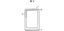
- FIG. 2 is a plan view showing an appearance of the mobile communication terminal 1 according to the present embodiment.
- the mobile communication terminal 1 is a mobile terminal that simultaneously performs LTE communication and WiFi communication, and includes an LTE transmission / reception unit 2, a modulation / demodulation processing unit 3, a WiFi transmission / reception unit 4, a modulation / demodulation processing unit 5, and a control unit. 6 is provided.
- the LTE transmission / reception unit 2 and the modulation / demodulation processing unit 3 are collectively referred to as an LTE radio unit 7 (first radio unit).
- the WiFi transmitting / receiving unit 4 and the modulation / demodulation processing unit 5 are collectively referred to as a WiFi wireless unit 8 (second wireless unit).
- the LTE transmission / reception unit 2 is a part that performs LTE communication, and includes a main antenna 21, a sub antenna 22, a switch 23, diplexers 24 and 25, a Band 21 Tx / Rx radio unit 26, a Band 1 Tx / Rx radio unit 27, and a Band 21 unit.
- An Rx radio unit 28 and a Band1 Rx radio unit 29 are provided.
- the main antenna 21 is disposed at the lower end of the mobile communication terminal 1
- the sub antenna 22 is disposed at the upper end of the mobile communication terminal 1.
- the switch 23 switches the connection between the main antenna 21 and the sub antenna 22 and the diplexers 24 and 25.
- the diplexer 24 is a filter interposed between the switch 23, the Band 21 Tx / Rx radio unit 26, and the Band 1 Tx / Rx radio unit 27. Remove frequency band signals. Specifically, regarding the signal between the switch 23 and the Band 21 Tx / Rx radio unit 26, a signal in the Band 21 frequency band (1.5 GHz band) is passed. As for the signal between the switch 23 and the Band1 Tx / Rx radio unit 27, a signal in the Band1 frequency band (2 GHz band) is passed.
- the diplexer 25 is a filter interposed between the switch 23, the Band 21 Rx radio unit 28, and the Band 1 Rx radio unit 29. The diplexer 25 passes signals in the pass band and signals in other frequency bands. Remove. Specifically, for the signal between the switch 23 and the Band 21 Rx radio unit 28, a signal in the Band 21 frequency band is passed. As for the signal between the switch 23 and the Band1 Rx radio unit 29, a signal in the Band1 frequency band is passed.
- the Band 21 Tx / Rx radio unit 26 is a part that performs LTE communication using the Band 21, and includes a duplexer 261, an LNA (Low Noise Amplifier) 262, a mixer 263, an A / D converter 264, a D / A converter 265, a mixer 266, and A power amplifier 267 is provided.
- the duplexer 261 is a filter interposed between the diplexer 24, the LNA 262, and the power amplifier 267, and passes a signal in the pass band and removes a signal in the other frequency band. Specifically, for the signal from the diplexer 24 to the LNA 262, a signal in the reception frequency band of Band 21 is passed.
- the LNA 262, the mixer 263, and the A / D converter 264 are configured as a receiving circuit.
- the LNA 262 is a low noise amplifier that selects and amplifies the signal from the duplexer 261.
- the mixer 263 is a frequency converter that converts the signal from the LNA 262 to a constant low frequency.
- the A / D converter 264 performs A / D conversion on the signal from the mixer 263 and outputs the signal to the modulation / demodulation processing unit 3.
- the D / A converter 265, the mixer 266, and the power amplifier 267 are configured as a transmission circuit.
- the D / A converter 265 D / A converts the signal from the modulation / demodulation processing unit 3 and outputs it to the mixer 266.
- the mixer 266 is a frequency converter that converts the signal from the D / A converter 265 into a constant low frequency.
- the power amplifier 267 is an amplifier that amplifies the signal from the mixer 266.
- the Band 1 Tx / Rx radio unit 27 performs LTE communication using Band 1 and includes a duplexer 271, an LNA 272, a mixer 273, an A / D converter 274, a D / A converter 275, a mixer 276, and a power amplifier 277. ing.
- the duplexer 271 is a filter interposed between the diplexer 24, the LNA 272, and the power amplifier 277, and passes a signal in the pass band and removes a signal in the other frequency band. Specifically, for the signal from the diplexer 24 to the LNA 272, the signal in the Band1 reception frequency band is passed. As for the signal from the power amplifier 277 to the diplexer 24, a signal in the Band1 transmission frequency band is passed.
- the LNA 272, the mixer 273, and the A / D converter 274 are configured as a receiving circuit.
- the LNA 272 is a low noise amplifier that selects and amplifies the signal from the duplexer 271.
- the mixer 273 is a frequency converter that converts the signal from the LNA 272 to a constant low frequency.
- the A / D converter 274 performs A / D conversion on the signal from the mixer 273 and outputs it to the modulation / demodulation processing unit 3.
- the D / A converter 275, the mixer 276, and the power amplifier 277 are configured as a transmission circuit.
- the D / A converter 275 D / A converts the signal from the modulation / demodulation processing unit 3 and outputs it to the mixer 276.
- the mixer 276 is a frequency converter that converts the signal from the D / A converter 275 into a constant low frequency.
- the power amplifier 277 is an amplifier that amplifies the signal from the mixer 276.
- the Band 21 Rx radio unit 28 is a part that performs LTE reception using Band 21, and includes a filter 281, an LNA 282, a mixer 283, and an A / D converter 284.
- the filter 281 is a filter interposed between the diplexer 25 and the LNA 282, and passes signals in the pass band and removes signals in other frequency bands. Specifically, with respect to the signal from the diplexer 25 to the LNA 282, the signal in the reception frequency band of Band 21 is passed.
- the LNA 282 is a low noise amplifier that selects and amplifies the signal from the filter 281.
- the mixer 283 is a frequency converter that converts the signal from the LNA 282 to a constant low frequency.
- the A / D converter 284 performs A / D conversion on the signal from the mixer 283 and outputs the signal to the modulation / demodulation processing unit 3.
- the Band1 Rx radio unit 29 is a part that performs LTE reception using Band1, and includes a filter 291, an LNA 292, a mixer 293, and an A / D converter 294.
- the filter 291 is a filter interposed between the diplexer 25 and the LNA 292, and passes a signal in the pass band and removes signals in other frequency bands. Specifically, with respect to the signal from the diplexer 25 to the LNA 292, the signal in the reception frequency band of Band1 is passed.
- the LNA 292 is a low noise amplifier that selects and amplifies the signal from the filter 291.
- the mixer 293 is a frequency converter that converts the signal from the LNA 292 to a constant low frequency.
- the A / D converter 294 performs A / D conversion on the signal from the mixer 293 and outputs the signal to the modulation / demodulation processing unit 3.
- the modulation / demodulation processing unit 3 is a part that performs modulation / demodulation processing of a digital signal related to LTE communication, and is interposed between the LTE transmission / reception unit 2 and the control unit 6. Specifically, in LTE transmission, the digital signal from the control unit 6 is modulated and output to the Band 21 Tx / Rx radio unit 26 and the Band 1 Tx / Rx radio unit 27. Further, in LTE reception, the control unit 6 demodulates digital signals from the Band21 Tx / Rx radio unit 26, the Band1 Tx / Rx radio unit 27, the Band21 Rx radio unit 28, and the Band1 Rx radio unit 29. Output to.
- the WiFi transceiver unit 4 is a part that performs WiFi communication, and includes a WiFi antenna 41, a switch 42, a filter 43, an LNA 44, a mixer 45, an A / D converter 46, a D / A converter 47, a mixer 48, a power amplifier 49, and A filter 4A is provided.
- the WiFi antenna 41 performs transmission / reception using a TDD (Time Division Duplex) method.
- the TDD system is called time division duplex, and uses the same frequency for transmission and reception.
- the switch 42 is switched in accordance with the transmission and reception timings, so that the transmission circuit including the filter 4A or the reception circuit including the filter 43 is connected.
- the WiFi antenna 41 is arranged on the upper left side of the mobile communication terminal 1.
- the filter 43, LNA 44, mixer 45, and A / D converter 46 are configured as a receiving circuit.
- the filter 43 is a filter interposed between the switch 42 and the LNA 44, and passes the signal in the pass band and removes the signal in the other frequency band. Specifically, with respect to the signal from the switch 42 to the LNA 44, a signal in the reception frequency band of WiFi communication is passed.
- the LNA 44 is a low noise amplifier that selects and amplifies the signal from the filter 43.
- the mixer 45 is a frequency converter that converts the signal from the LNA 44 into a constant low frequency.
- the A / D converter 46 A / D converts the signal from the mixer 45 and outputs it to the modulation / demodulation processing unit 3.
- the D / A converter 47, the mixer 48, the power amplifier 49, and the filter 4A are configured as a transmission circuit.
- the D / A converter 47 D / A converts the signal from the modulation / demodulation processing unit 3 and outputs it to the mixer 48.
- the mixer 48 is a frequency converter that converts the signal from the D / A converter 47 into a constant low frequency.
- the power amplifier 49 is an amplifier that amplifies the signal from the mixer 48.
- the filter 4A is a filter interposed between the switch 42 and the power amplifier 49, and allows a signal in the pass band to pass therethrough and removes signals in other frequency bands. Specifically, with respect to the signal from the power amplifier 49 to the switch 42, the signal in the transmission frequency band of WiFi communication is passed.
- the modulation / demodulation processing unit 5 is a part that performs modulation / demodulation processing of a digital signal related to WiFi communication, and is interposed between the WiFi transmission / reception unit 4 and the control unit 6. Specifically, in WiFi transmission, the digital signal from the control unit 6 is modulated and output to a transmission circuit including the D / A converter 47. In WiFi reception, the digital signal from the receiving circuit including the A / D converter 46 is demodulated and output to the control unit 6.
- the control unit 6 acquires the demodulated digital signal (reception signal) from the modulation / demodulation processing units 3 and 5 and outputs a digital signal (transmission signal) to be modulated to the modulation / demodulation processing units 3 and 5.
- the control unit 6 calculates the frequency of the intermodulation wave generated from the radio wave transmitted by the LTE radio unit 7 and the radio wave transmitted by the WiFi radio unit 8 from the transmission frequency of the LTE radio unit 7 and the transmission frequency of the WiFi radio unit 8. Then, when the calculated frequency of the intermodulation wave and the reception frequency of the LTE radio unit 7 overlap, the operation of at least one of the LTE radio unit 7 and the WiFi radio unit 8 is switched from the normal mode to the low interference mode.
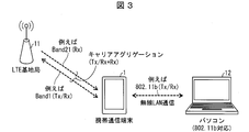
- FIG. 3 is a network configuration diagram showing a communication function of the mobile communication terminal 1 according to the present embodiment.
- the mobile communication terminal 1 supports carrier aggregation and wireless LAN communication.
- Carrier aggregation performs communication using a plurality of LTE carriers, and is a technology that uses a plurality of different frequency bands simultaneously.
- the mobile communication terminal 1 performs transmission / reception by Band 1 and reception by Band 21 simultaneously with the LTE base station 11.
- a wireless LAN refers to a LAN system that transmits and receives data using wireless communication.
- the mobile communication terminal 1 performs wireless LAN transmission / reception by 802.11b with the personal computer 12 which is a master station as a slave station, for example.
- FIG. 4 is a table showing a correspondence relationship between the frequency band corresponding to each 802.11b channel of WiFi communication and the frequency band of the intermodulation wave to be generated according to the present embodiment.
- the radio field intensity of the intermodulation wave is the transmission power of each radio wave that causes the generation of the intermodulation wave, the separation state (isolation) between the transmission antennas, and the linearity characteristics of the circuit element that generates the intermodulation distortion. Depends on etc.
- ⁇ indicates that transmission diversity is available
- x indicates that transmission diversity is not available.
- transmission diversity there is a method of receiving radio waves using two or more antennas and using an antenna with high radio field intensity at the time of reception for transmission. For example, in LTE communication in the mobile communication terminal 1 of FIG. 2, either the main antenna 21 or the sub-antenna 22 is used as a transmission antenna according to the received radio wave intensity that changes from time to time.
- FIG. 4 shows the frequency band of the third-order intermodulation distortion (IM3) generated by the transmission radio wave in LTE communication and the transmission radio wave in WiFi communication. It is also possible to take into account the calculated frequency band when calculating the frequency band of IM2) or higher-order intermodulation distortion of 4th order or higher and making a determination on the availability of transmission diversity.
- IM3 third-order intermodulation distortion
- FIG. 4 (a) is a table in the case where the uplink use band of Band1 in LTE communication is 1940 to 1960 [MHz].
- an intermodulation wave is generated by the transmission wave of Band1 in LTE communication and the transmission wave of each channel in WiFi communication.
- the transmission diversity operation should be stopped depending on whether or not the frequency band of the intermodulation wave and the reception frequency band of Band 21 (1495.9 to 1510.9 [MHz]) overlap (that is, cannot be used) ) Or not.
- the frequency bands of intermodulation waves that overlap the Band21 reception frequency band are 1458 to 1518, 1451 to 1513, 1446 to 1508, 1441 to 1503, and 1436 to 1498.
- the 802.11b channel to be transmitted is 1 to 5
- transmit diversity cannot be used.
- the 802.11b channel is 6 to 14, transmit diversity can be used.
- FIG. 4B is a table in the case where the uplink use band of Band 21 in LTE communication is 1447.9 to 1462.9 [MHz].
- an intermodulation wave is generated by the transmission radio wave of Band 21 in LTE communication and the transmission radio wave of each channel in WiFi communication.
- Whether or not the transmission diversity operation should be stopped (that is, cannot be used) is determined depending on whether or not the frequency band of the intermodulation wave overlaps with the reception frequency band of Band1.
- FIG. 4 (b) there is no intermodulation wave frequency band that overlaps the Band1 reception frequency band. Therefore, even if the 802.11b channel is any one of 1 to 14, transmission diversity can be used. is there.
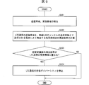
- FIG. 5 is a flowchart showing processing of the mobile communication terminal 1 according to the present embodiment.
- the control unit 6 detects a transmission band and a reception band related to data communication (S501).
- the transmission band and the reception band may be the frequency band itself, or may be channel information that can be converted into the frequency band by a table or the like.
- the control unit 6 obtains the Band 1 transmission band, the reception band, and the Band 21 reception band from the LTE base station 11 and uses WiFi for wireless communication with the personal computer 12.
- Acquires 802.11b channel information of communication is specified from the 802.11b channel information using the table of FIG.
- the control unit 6 calculates the frequency band of the intermodulation wave generated by the radio waves transmitted in the LTE communication transmission band and the wireless LAN channel transmission band detected in S501 (S502).
- the frequency band of the intermodulation wave may be calculated each time, or a table of the frequency band of the intermodulation wave calculated in advance may be stored and the table may be referred to.
- the control unit 6 determines whether or not the frequency band of the intermodulation wave calculated in S502 overlaps the reception band of LTE communication (S503).
- the control unit 6 stops the transmission diversity of LTE communication (S504).
- the control unit 6 controls the switch 23 to select an antenna to be used for LTE communication. Specifically, transmission diversity is stopped, and a low-interference antenna that has been confirmed in advance that the deterioration in reception sensitivity of LTE communication is within an allowable range is fixed as a transmission antenna of LTE communication.
- the LTE radio unit 7 when radio waves are transmitted using each simultaneously with the radio wave transmission by the LTE radio unit 7.
- the deterioration of the reception sensitivity is measured in advance, and it is confirmed in advance whether or not the deterioration of the reception sensitivity is within an allowable range.
- the antenna determined that the degradation of the reception sensitivity is within the allowable range is set in advance as a low interference antenna used in the low interference mode, and the antenna whose degradation of the reception sensitivity is determined to be within the allowable range is It is set in advance as a low interference antenna used in the low interference mode. As shown in FIG.
- the mobile communication terminal 1 includes a main antenna 21 and a sub antenna 22 as LTE communication antennas.
- the main antenna 21 that is away from the WiFi antenna 41 that is a transmission antenna of WiFi communication and has high inter-antenna isolation with the WiFi antenna 41 is set in advance as a low interference antenna, and is close to the WiFi antenna 41.
- the sub antenna 22 having low inter-antenna isolation with the WiFi antenna 41 is set in advance as a non-low interference antenna.
- the control unit is switched to the low-interference mode. 6 fixes the main antenna 21 which is a low interference antenna as a transmission antenna of LTE communication.
- the control unit 6 may fix the low interference antenna corresponding to the antenna currently used by the WiFi radio unit 8 as a transmission antenna for LTE communication.
- the reception sensitivity deterioration of LTE communication is within an allowable range.
- the control unit 6 determines that there is no deterioration in the sensitivity of the reception antenna due to the intermodulation wave, and skips the process of S504 By doing so, the transmission diversity of LTE communication is continued.
- Embodiment 2 of the present invention will be described below with reference to FIGS. 1 to 4 and FIG.
- the control unit overlaps the calculated frequency of the intermodulation wave with the reception frequency of the first radio unit, and the transmission power of the first radio unit and the second radio unit.
- the transmission power of the first radio unit satisfies a predetermined condition, the operation of the first radio unit is switched from the normal mode to the low interference mode.
- 1 to 4 are the same as those described in the first embodiment.
- FIG. 6 is a flowchart showing processing of the mobile communication terminal 1 according to the present embodiment. Note that the processing of S601 to S603 and S605 is the same as the processing of S501 to S504 of the first embodiment, and thus detailed description thereof is omitted.
- the control unit 6 detects a transmission band and a reception band related to data communication (S601).
- the control unit 6 calculates the frequency band of the intermodulation wave generated by the radio wave transmitted in the transmission band of the LTE communication and the transmission band of the wireless LAN channel detected in S601 (S602).
- the control unit 6 determines whether or not the frequency band of the intermodulation wave calculated in S602 overlaps the reception band of LTE communication (S603).
- the control unit 6 determines whether or not the transmission power of the LTE communication and the WiFi communication satisfies a predetermined condition ( S604).
- the predetermined condition is, for example, a condition that transmission power of LTE communication and WiFi communication is a predetermined value or more, but is not limited thereto.
- the control unit 6 stops the transmission diversity of LTE communication (S605).
- the control unit 6 determines that there is no deterioration in sensitivity of the receiving antenna due to the intermodulation wave, and skips the processing of S605, thereby continuing the transmission diversity of LTE communication.
- the second radio unit transmits radio waves in the low interference mode with transmission power smaller than that in the normal mode.
- the first radio unit includes a plurality of antennas, and in the low interference mode, the second radio unit transmits radio waves with transmission power corresponding to the antenna used by the first radio unit for radio wave transmission.
- To do. 1 to 4 are the same as those described in the first embodiment.
- FIG. 7 is a flowchart showing Example 1 of processing of the mobile communication terminal 1 according to the present embodiment. Note that the processing in S701 to S703 is the same as the processing in S501 to S503 in the first embodiment, and thus detailed description thereof is omitted.
- the control unit 6 detects a transmission band and a reception band related to data communication (S701).
- the control unit 6 calculates the frequency band of the intermodulation wave generated by the radio wave transmitted in the LTE communication transmission band and the wireless LAN channel transmission band detected in S701 (S702).
- the control unit 6 determines whether or not the frequency band of the intermodulation wave calculated in S702 overlaps the reception band of LTE communication (S703).
- the control unit 6 switches from the normal mode to the low interference mode, and reduces the transmission power of WiFi communication compared to the normal mode. (S704).
- the control unit 6 controls the power amplifier 49 to reduce the transmission power of WiFi communication.
- the control unit 6 generates radio waves of intermodulation waves generated according to the transmission power of LTE communication and the transmission antenna used for LTE communication (inter-antenna isolation between the WiFi antenna 41). Control is performed so that the strength is such that the sensitivity deterioration of LTE reception falls within an allowable range.
- the reception sensitivity of the LTE radio unit 7 is degraded. Measure in advance. Then, when the antenna used by the LTE radio unit 7 for transmitting radio waves and the transmission power of the LTE radio unit 7 are given, the WiFi radio unit 8 The degree to which the transmission power should be reduced is calculated in advance and stored in a table or the like that can be referred to by the control unit 6. And the control part 6 should just reduce the transmission power of the WiFi radio
- the control unit 6 may reduce the transmission power of the WiFi antenna 41 as the transmission power of the main antenna 21 and the sub antenna 22 increases. Further, when the main antenna 21 is used as a transmission antenna for LTE communication, the control unit 6 has a high inter-antenna isolation between the main antenna 21 and the WiFi antenna 41, so that the transmission power of the WiFi antenna 41 is slightly increased. Lower. On the other hand, when the sub antenna 22 is used as a transmission antenna for LTE communication, since the isolation between the main antenna 21 and the WiFi antenna 41 is low, the transmission power of the WiFi antenna 41 may be greatly reduced. Good. Further, the control unit 6 may reduce the transmission power of the WiFi communication in consideration of either the transmission power of the LTE communication or the transmission antenna used for the LTE communication.
- the control unit 6 determines that there is no sensitivity deterioration of the reception antenna due to the intermodulation wave, and performs the process of S704. By skipping, the transmission power of WiFi communication is not reduced.
- the mobile communication terminal 1 may perform any one of the processes according to each embodiment, or according to the first and third embodiments.
- the processing may be executed simultaneously, or the processing according to the second and third embodiments may be executed simultaneously.
- a wireless communication device (mobile communication terminal 1) according to aspect 1 of the present invention includes a first wireless unit (LTE wireless unit 7) that transmits and receives radio waves, a second wireless unit (WiFi wireless unit 8) that transmits at least radio waves, and The frequency of the intermodulation wave generated from the radio wave transmitted by the first radio unit and the radio wave transmitted by the second radio unit is calculated from the transmission frequency of the first radio unit and the transmission frequency of the second radio unit.
- wireless communication apparatus is 1st radio
- the operation of at least one of the unit and the second radio unit is switched from the normal mode to the low interference mode.
- the first radio unit By switching the operation of at least one of the unit and the second radio unit from the normal mode to the low interference mode, it is possible to reduce deterioration of reception sensitivity due to the intermodulation wave.
- the wireless communication apparatus is the wireless communication apparatus according to aspect 1, in which the first wireless unit is used in advance in the low interference mode and the low interference antenna (main antenna 21) set to be used in the low interference mode in advance.
- the radio wave may be transmitted using only the low interference antenna.
- wireless communication apparatus is provided with the low interference antenna and the non-low interference antenna.
- the first radio unit transmits radio waves using an antenna selected from a low interference antenna and a non-low interference antenna in the normal mode, and transmits radio waves using only the low interference antenna in the low interference mode. To do. Therefore, in the wireless communication device, it is possible to reduce deterioration in reception sensitivity due to intermodulation waves.
- the wireless communication apparatus is the wireless communication apparatus according to aspect 2, in which the first wireless unit performs transmission diversity using the low interference antenna and the non-low interference antenna in the normal mode, and performs the low interference.
- radio waves may be transmitted using only the low interference antenna without performing the transmission diversity.
- the first wireless unit of the wireless communication apparatus performs transmission diversity using the low interference antenna and the non-low interference antenna in the normal mode, and does not perform transmission diversity in the low interference mode. Transmit radio waves using only low-interference antennas. That is, in the wireless communication apparatus, transmission diversity is performed as much as possible, and transmission diversity is stopped only when there is a possibility of deterioration in reception sensitivity. Therefore, efficient data transmission can be performed.
- the wireless communication apparatus is the wireless communication apparatus according to aspects 1 to 3, wherein the control unit overlaps the calculated frequency of the intermodulation wave and the reception frequency of the first wireless unit, and the first wireless unit.
- the control unit of the wireless communication device not only overlaps the frequency of the intermodulation wave and the reception frequency of the first wireless unit, but also includes the radio wave transmitted by the first wireless unit and the second wireless unit.
- the operation of the first radio unit is switched from the normal mode to the low interference mode in consideration of the transmission power of the radio wave transmitted by the radio, that is, the radio wave intensity of the intermodulation wave. Therefore, since the low-interference mode is switched when there is a high possibility that the sensitivity of the receiving antenna is deteriorated, it is possible to reduce the deterioration of the reception sensitivity due to the intermodulation wave while continuing the normal mode as much as possible.
- the second wireless unit in the low interference mode, may transmit radio waves with transmission power smaller than that in the normal mode.
- wireless part transmits an electromagnetic wave with transmission power smaller than normal mode in low interference mode.
- the present invention can be used for a wireless communication device.
Landscapes
- Engineering & Computer Science (AREA)
- Computer Networks & Wireless Communication (AREA)
- Signal Processing (AREA)
- Transceivers (AREA)
- Mobile Radio Communication Systems (AREA)
Abstract
Selon la présente invention, un terminal de communication mobile (1) calcule la fréquence d'une onde d'intermodulation produite à partir d'une onde radio transmise par une unité sans fil LTE (7) et à partir d'une onde radio transmise par une unité sans fil WiFi (8), et commute le fonctionnement soit de l'unité sans fil LTE (7), soit de l'unité sans fil WiFi (8) à partir d'un mode normal vers un mode de faible brouillage lorsque la fréquence calculée de l'onde d'intermodulation chevauche la fréquence reçue par l'unité sans fil LTE (7).
Applications Claiming Priority (2)
| Application Number | Priority Date | Filing Date | Title |
|---|---|---|---|
| JP2015101212 | 2015-05-18 | ||
| JP2015-101212 | 2015-05-18 |
Publications (1)
| Publication Number | Publication Date |
|---|---|
| WO2016185871A1 true WO2016185871A1 (fr) | 2016-11-24 |
Family
ID=57320007
Family Applications (1)
| Application Number | Title | Priority Date | Filing Date |
|---|---|---|---|
| PCT/JP2016/062777 Ceased WO2016185871A1 (fr) | 2015-05-18 | 2016-04-22 | Dispositif de communication sans fil |
Country Status (1)
| Country | Link |
|---|---|
| WO (1) | WO2016185871A1 (fr) |
Cited By (2)
| Publication number | Priority date | Publication date | Assignee | Title |
|---|---|---|---|---|
| CN110197944A (zh) * | 2018-02-26 | 2019-09-03 | 矢崎总业株式会社 | 集成天线模块以及车载系统 |
| JP2024540702A (ja) * | 2021-12-03 | 2024-11-01 | テレフオンアクチーボラゲット エルエム エリクソン(パブル) | ダウンリンク攻撃者による干渉の低減 |
Citations (3)
| Publication number | Priority date | Publication date | Assignee | Title |
|---|---|---|---|---|
| JP2009267678A (ja) * | 2008-04-24 | 2009-11-12 | Panasonic Corp | 通信装置及び通信方法 |
| WO2013089891A1 (fr) * | 2011-12-12 | 2013-06-20 | Apple Inc. | Dispositif électronique radio à circuits de commutation d'antennes |
| JP2015041791A (ja) * | 2013-08-20 | 2015-03-02 | シャープ株式会社 | 携帯端末装置 |
-
2016
- 2016-04-22 WO PCT/JP2016/062777 patent/WO2016185871A1/fr not_active Ceased
Patent Citations (3)
| Publication number | Priority date | Publication date | Assignee | Title |
|---|---|---|---|---|
| JP2009267678A (ja) * | 2008-04-24 | 2009-11-12 | Panasonic Corp | 通信装置及び通信方法 |
| WO2013089891A1 (fr) * | 2011-12-12 | 2013-06-20 | Apple Inc. | Dispositif électronique radio à circuits de commutation d'antennes |
| JP2015041791A (ja) * | 2013-08-20 | 2015-03-02 | シャープ株式会社 | 携帯端末装置 |
Cited By (5)
| Publication number | Priority date | Publication date | Assignee | Title |
|---|---|---|---|---|
| CN110197944A (zh) * | 2018-02-26 | 2019-09-03 | 矢崎总业株式会社 | 集成天线模块以及车载系统 |
| JP2019149612A (ja) * | 2018-02-26 | 2019-09-05 | 矢崎総業株式会社 | 統合アンテナモジュール、及び、車載システム |
| US11056775B2 (en) | 2018-02-26 | 2021-07-06 | Yazaki Corporation | Integrated antenna module and in-vehicle system |
| JP2024540702A (ja) * | 2021-12-03 | 2024-11-01 | テレフオンアクチーボラゲット エルエム エリクソン(パブル) | ダウンリンク攻撃者による干渉の低減 |
| JP7742487B2 (ja) | 2021-12-03 | 2025-09-19 | テレフオンアクチーボラゲット エルエム エリクソン(パブル) | ダウンリンク攻撃者による干渉の低減 |
Similar Documents
| Publication | Publication Date | Title |
|---|---|---|
| US20240405733A1 (en) | Multi-mode power amplifier system and related wireless devices and methods | |
| US11916577B2 (en) | Systems and methods for duplexer circuits having signal cancellation paths | |
| US11855328B2 (en) | Remote compensators for mobile devices | |
| US10985461B2 (en) | Terminal device | |
| US9161386B1 (en) | Hybrid LMR transceiver with LTE and dynamic antenna control | |
| CN112532282B (zh) | 通信方法和终端设备 | |
| US11863217B2 (en) | Module arranged to bidirectionally pass coupled power signal | |
| US10499352B2 (en) | Power amplification module for multiple bands and multiple standards | |
| US20240244540A1 (en) | Transmission power determination for forwarding nodes in wireless communication systems | |
| US12592725B2 (en) | Configurable filter bands for radio frequency communication | |
| US9344264B2 (en) | Reversible radio architecture between transmission and reception functions in a mobile communication system | |
| WO2016185871A1 (fr) | Dispositif de communication sans fil | |
| JP6035120B2 (ja) | エネルギ消費削減方法及び無線通信端末 | |
| US20160119016A1 (en) | Antenna switching in a communication circuit | |
| CN116980932A (zh) | 基站及其通信方法 | |
| JP2004289713A (ja) | 周波数変換装置 | |
| JP2009206649A (ja) | 無線装置 | |
| JP2013070147A (ja) | 基地局装置、基地局制御方法 |
Legal Events
| Date | Code | Title | Description |
|---|---|---|---|
| 121 | Ep: the epo has been informed by wipo that ep was designated in this application |
Ref document number: 16796265 Country of ref document: EP Kind code of ref document: A1 |
|
| NENP | Non-entry into the national phase |
Ref country code: DE |
|
| 122 | Ep: pct application non-entry in european phase |
Ref document number: 16796265 Country of ref document: EP Kind code of ref document: A1 |
|
| NENP | Non-entry into the national phase |
Ref country code: JP |