WO2016186026A1 - フィルム収納容器、フィルム、フィルム巻回体及びフィルム収納体 - Google Patents
フィルム収納容器、フィルム、フィルム巻回体及びフィルム収納体 Download PDFInfo
- Publication number
- WO2016186026A1 WO2016186026A1 PCT/JP2016/064291 JP2016064291W WO2016186026A1 WO 2016186026 A1 WO2016186026 A1 WO 2016186026A1 JP 2016064291 W JP2016064291 W JP 2016064291W WO 2016186026 A1 WO2016186026 A1 WO 2016186026A1
- Authority
- WO
- WIPO (PCT)
- Prior art keywords
- film
- container
- plate
- cutting
- width direction
- Prior art date
- Legal status (The legal status is an assumption and is not a legal conclusion. Google has not performed a legal analysis and makes no representation as to the accuracy of the status listed.)
- Ceased
Links
Images






Classifications
-
- B—PERFORMING OPERATIONS; TRANSPORTING
- B65—CONVEYING; PACKING; STORING; HANDLING THIN OR FILAMENTARY MATERIAL
- B65D—CONTAINERS FOR STORAGE OR TRANSPORT OF ARTICLES OR MATERIALS, e.g. BAGS, BARRELS, BOTTLES, BOXES, CANS, CARTONS, CRATES, DRUMS, JARS, TANKS, HOPPERS, FORWARDING CONTAINERS; ACCESSORIES, CLOSURES, OR FITTINGS THEREFOR; PACKAGING ELEMENTS; PACKAGES
- B65D85/00—Containers, packaging elements or packages, specially adapted for particular articles or materials
- B65D85/67—Containers, packaging elements or packages, specially adapted for particular articles or materials for web or tape-like material
- B65D85/671—Containers, packaging elements or packages, specially adapted for particular articles or materials for web or tape-like material wound in flat spiral form
- B65D85/672—Containers, packaging elements or packages, specially adapted for particular articles or materials for web or tape-like material wound in flat spiral form on cores
-
- B—PERFORMING OPERATIONS; TRANSPORTING
- B65—CONVEYING; PACKING; STORING; HANDLING THIN OR FILAMENTARY MATERIAL
- B65D—CONTAINERS FOR STORAGE OR TRANSPORT OF ARTICLES OR MATERIALS, e.g. BAGS, BARRELS, BOTTLES, BOXES, CANS, CARTONS, CRATES, DRUMS, JARS, TANKS, HOPPERS, FORWARDING CONTAINERS; ACCESSORIES, CLOSURES, OR FITTINGS THEREFOR; PACKAGING ELEMENTS; PACKAGES
- B65D25/00—Details of other kinds or types of rigid or semi-rigid containers
- B65D25/38—Devices for discharging contents
- B65D25/52—Devices for discharging successive articles or portions of contents
-
- B—PERFORMING OPERATIONS; TRANSPORTING
- B65—CONVEYING; PACKING; STORING; HANDLING THIN OR FILAMENTARY MATERIAL
- B65D—CONTAINERS FOR STORAGE OR TRANSPORT OF ARTICLES OR MATERIALS, e.g. BAGS, BARRELS, BOTTLES, BOXES, CANS, CARTONS, CRATES, DRUMS, JARS, TANKS, HOPPERS, FORWARDING CONTAINERS; ACCESSORIES, CLOSURES, OR FITTINGS THEREFOR; PACKAGING ELEMENTS; PACKAGES
- B65D5/00—Rigid or semi-rigid containers of polygonal cross-section, e.g. boxes, cartons or trays, formed by folding or erecting one or more blanks made of paper
- B65D5/42—Details of containers or of foldable or erectable container blanks
- B65D5/72—Contents-dispensing means
-
- B—PERFORMING OPERATIONS; TRANSPORTING
- B65—CONVEYING; PACKING; STORING; HANDLING THIN OR FILAMENTARY MATERIAL
- B65D—CONTAINERS FOR STORAGE OR TRANSPORT OF ARTICLES OR MATERIALS, e.g. BAGS, BARRELS, BOTTLES, BOXES, CANS, CARTONS, CRATES, DRUMS, JARS, TANKS, HOPPERS, FORWARDING CONTAINERS; ACCESSORIES, CLOSURES, OR FITTINGS THEREFOR; PACKAGING ELEMENTS; PACKAGES
- B65D83/00—Containers or packages with special means for dispensing contents
- B65D83/08—Containers or packages with special means for dispensing contents for dispensing thin flat articles in succession
- B65D83/0805—Containers or packages with special means for dispensing contents for dispensing thin flat articles in succession through an aperture in a wall
- B65D83/0811—Containers or packages with special means for dispensing contents for dispensing thin flat articles in succession through an aperture in a wall with means for assisting dispensing
- B65D83/0835—Containers or packages with special means for dispensing contents for dispensing thin flat articles in succession through an aperture in a wall with means for assisting dispensing the articles being pulled out of the container
-
- B—PERFORMING OPERATIONS; TRANSPORTING
- B65—CONVEYING; PACKING; STORING; HANDLING THIN OR FILAMENTARY MATERIAL
- B65D—CONTAINERS FOR STORAGE OR TRANSPORT OF ARTICLES OR MATERIALS, e.g. BAGS, BARRELS, BOTTLES, BOXES, CANS, CARTONS, CRATES, DRUMS, JARS, TANKS, HOPPERS, FORWARDING CONTAINERS; ACCESSORIES, CLOSURES, OR FITTINGS THEREFOR; PACKAGING ELEMENTS; PACKAGES
- B65D83/00—Containers or packages with special means for dispensing contents
- B65D83/08—Containers or packages with special means for dispensing contents for dispensing thin flat articles in succession
- B65D83/0805—Containers or packages with special means for dispensing contents for dispensing thin flat articles in succession through an aperture in a wall
- B65D83/0811—Containers or packages with special means for dispensing contents for dispensing thin flat articles in succession through an aperture in a wall with means for assisting dispensing
- B65D83/0841—Containers or packages with special means for dispensing contents for dispensing thin flat articles in succession through an aperture in a wall with means for assisting dispensing and for cutting interconnected articles
-
- B—PERFORMING OPERATIONS; TRANSPORTING
- B65—CONVEYING; PACKING; STORING; HANDLING THIN OR FILAMENTARY MATERIAL
- B65D—CONTAINERS FOR STORAGE OR TRANSPORT OF ARTICLES OR MATERIALS, e.g. BAGS, BARRELS, BOTTLES, BOXES, CANS, CARTONS, CRATES, DRUMS, JARS, TANKS, HOPPERS, FORWARDING CONTAINERS; ACCESSORIES, CLOSURES, OR FITTINGS THEREFOR; PACKAGING ELEMENTS; PACKAGES
- B65D85/00—Containers, packaging elements or packages, specially adapted for particular articles or materials
- B65D85/67—Containers, packaging elements or packages, specially adapted for particular articles or materials for web or tape-like material
- B65D85/671—Containers, packaging elements or packages, specially adapted for particular articles or materials for web or tape-like material wound in flat spiral form
Definitions
- the present invention relates to a film storage container, a film, a film winding body, and a film storage body.
- a wrapping film for food packaging, an aluminum foil, a cooking sheet, a film for printing and plate making, etc. (hereinafter collectively referred to as “film”) is wound and accommodated.
- a film container has been proposed (see, for example, Patent Documents 1 and 2).
- the conventional film storage container as described in Patent Documents 1 and 2 is provided with a blade and a slide cutter for cutting the drawn film, the user may be injured by the blade and the slide cutter. Still exists. Further, since the blade and the slide cutter are made of a material (metal or synthetic resin) different from that of the storage container, it has been necessary to separate them at the time of disposal. Furthermore, in order to produce such a conventional film storage container, it is necessary to prepare a blade and a slide cutter separately and attach them to the container body, which causes a problem of labor and cost.
- JP 2010-247873 A Japanese Patent Laid-Open No. 03-288845 European Patent Application No. 1270437 International Publication No. 2012/157711 JP 2014-141262 A
- the present invention has been made in view of such circumstances, and provides a film storage container that is extremely safe, can save time and labor for sorting, and can reduce labor and cost during production.
- the purpose is to do.
- Another object of the present invention is to provide a film that does not break from the end even when tension is applied, and that allows the user to start cutting stably with a small operation.
- a film storage container includes a container body having a storage space for storing a wound body of film, and the film of the wound body stored in the storage space to the outside of the container body.
- the container body has a top plate, a front plate, a bottom plate, a pair of side plates, and a rear plate, and is formed by the front plate, the bottom plate, the side plate, and the rear plate.
- a protruding piece for fixing the top plate is inserted, and the outlet is provided on the top plate.
- a notch part can be provided in a top plate, and it can comprise so that a protrusion piece may be inserted in a notch part.
- the film does not necessarily have a cutting start portion.
- the top plate is fixed to the main body (formed by the front plate, the bottom plate, the pair of side plates and the rear plate) when the film is drawn out from the outlet provided on the top plate of the container body. be able to. Accordingly, it is possible to prevent the top plate from being lifted when the film is drawn out, and to prevent the top plate from sinking due to long-term use.
- a container body formed in a substantially rectangular parallelepiped shape is adopted, and an outlet is formed on one surface of the six surfaces constituting the container body so as to extend along the width direction.
- a temporary anchoring part that temporarily attaches the film by applying an adhesive force or a frictional force to the film drawn out of the container main body from the outlet can be employed.
- the temporary anchoring portion can be formed so as to extend along the width direction at a position close to the drawing outlet on one surface of the container main body.
- the film is temporarily fixed by applying an adhesive force or a frictional force to the film drawn out from the outlet to the outside of the container body by the temporary holding portion (the film is drawn out from the outlet). Can be temporarily suppressed). Moreover, in that state, by applying a tearing force to a portion on the downstream side of the portion where the adhesive force or friction force of the film is applied, the film is aligned along the width direction (a direction substantially perpendicular to the drawing direction). Can be torn. Therefore, since the film can be easily torn along the width direction by hand without using a blade or a slide cutter for cutting the film, the container is extremely safe. The time and labor of separation can be saved, and labor and cost can be reduced when the container is manufactured.
- an adhesive force or a frictional force can be applied to the film drawn out from the outlet formed on one surface of the substantially rectangular parallelepiped container body at a position close to the outlet. Therefore, a tearing force can be applied to the film in a state where there is no slack or distortion and the drawing direction is not shifted, so that the film can be torn cleanly.
- an adhesive part that causes an adhesive force to act on the film drawn from the outlet to the outside of the container body can be adopted as the temporary holding part.
- the adhesion part comprised with the varnish application layer and the double-sided tape is employable.
- an adhesive force can be applied to the film drawn from the outlet to the outside of the container main body by the adhesive portion (temporary anchoring portion) formed of a varnish coating layer or a double-sided tape.
- a friction part that applies a frictional force to the film drawn from the outlet to the outside of the container body can be adopted as the temporary holding part.
- a friction portion made of a rubber material can be employed.
- a frictional force temporary retaining portion made of a rubber material can cause a frictional force to act on the film drawn out of the container body from the outlet.
- the film according to the present invention is configured to extend along a predetermined flow direction, and a cutting start point portion is provided in a portion excluding an end portion in a width direction substantially orthogonal to the flow direction. It is.
- the film can be easily cut by hand because the cutting start portion is provided in the portion excluding the end portion in the width direction of the film.
- a film having a cutting start portion provided at the end in the width direction it is necessary to twist the wrist largely (that is, a large movement is required for cutting).
- the film can be cut with a relatively small operation.
- an unexpected situation may occur in which the film is cut from the end in the width direction when tension is applied.
- the cutting start part when the cutting start part is provided in the part except the edge part of the width direction of a film, it can prevent that such a situation generate
- a cutting start point when a cutting start point is provided at the end in the width direction of the film, the end in the width direction of the film may be deformed when tension is applied, and may not function as the cutting start. If the cutting start point is provided in the portion excluding the end in the width direction of the film as described above, the deformation of the cutting start point is reduced even when tension is applied, and thus cutting can be started stably. .
- the gel fraction can be set to 10 to 60% by weight.
- the film can be easily cut even with a light force such as a finger.
- the cutting starting point In the film according to the present invention, at least one perforation can be adopted as the cutting starting point. Moreover, you may employ
- the cutting start portion can be provided continuously along the flow direction at a position near the end in the width direction or at a substantially central portion in the width direction. In particular, the cutting start point can be provided at a position 25 mm or more inside from the end in the width direction (a position where it is easy to pierce with a finger to open a penetration mark).
- the present invention provides a film winding body in which the above film is wound.
- the present invention provides a film storage body comprising the above-mentioned film winding body and a container body having a storage space for storing the film winding body.
- the container body may have a protrusion for assisting in cutting the film of the film winding body.
- the rectangular parallelepiped storage chamber formed by the wall surfaces of the front plate, the bottom plate, the rear plate, and the side plate is connected to the opening in the direction covering the storage chamber from the upper edge of the rear plate.
- the container body may not have a protrusion for assisting in cutting the film of the film winding body.
- the outlet formed in at least a part of the container main body, and from the outlet to the outside of the container main body. It is possible to employ a container main body having a temporary holding portion for temporarily fastening the film by applying an adhesive force or a frictional force to the obtained film.
- the film is preferably configured to be torn along the width direction substantially perpendicular to the flow direction, which is the drawing direction from the pull-out port, when a cutting force is applied from the cutting start point. .
- the film F is configured to extend along a predetermined flow direction, and a cutting start point S is provided in a portion excluding an end portion in a width direction substantially orthogonal to the flow direction.
- the film F is configured to be torn along the width direction when a cutting force is applied from the cutting starting point S as a starting point.
- the cutting starting point S is a part that becomes a starting point of cutting by being configured to be more fragile than the surrounding part.
- a perforation (through hole) H continuously along the flow direction at a position near the end of the film F in the width direction, a cutting start point having a predetermined width is obtained.
- Part S is formed.
- the distance W between the end portion in the width direction of the film F and the cutting starting point portion S (the center portion thereof) disposed near the end portion in the width direction of the film F is Setting it to 25 mm or more (for example, 30 to 40 mm) is preferable because it can be easily pierced with a finger to make a penetration mark in the film F.
- a wrapping film for food packaging containing a polyolefin-based resin that has been subjected to specific stretching or cross-linking treatment can be employed.
- polyolefin-type resin for example, the homopolymer of olefins, such as polyethylene, polypropylene, polybutene, poly 4-methylpentene, the copolymer of 2 or more types of olefins, or 1 or more types of olefins And copolymers of different components other than olefins.
- Polyolefin resin may be used individually by 1 type, or may use 2 or more types together.
- a film F that satisfies the following conditions when X-ray scattering is measured because it can be cut with good linearity.
- the azimuth distribution profile of the scattering intensity of 2 ⁇ 20.9 ° to 21.8 ° when X-ray having a wavelength of 0.154 nm is incident from the normal direction of the film and transmission wide-angle X-ray scattering is measured.
- the azimuth distribution profile has four scattering peaks, (ii) the spacing between adjacent scattering peaks of the four scattering peaks is 90 ° ⁇ 10 °, and (iii) the orientation component ratio R is 0.01 Preferably, it is 100 or less, and (iv) the average area of the four scattering peaks is 1 or more and 89 or less.
- the “film normal direction” refers to a direction that passes through one point on the surface of the film F and is perpendicular to the tangential plane at that point.
- A, B, C, and D are sequentially set from the smaller azimuth angle side of the four scattering peaks, and these scattering peak areas are SA, SB, SC, and SD.
- SA azimuth angle
- SC SC
- SD SD
- the area S of each scattering peak is defined by the following formula (2).
- ⁇ 1 and ⁇ 2 are integral upper and lower limits ( ⁇ 1 ⁇ 2), and ⁇ where I ′ ( ⁇ ) sandwiching each scattering peak takes a minimum value is used.
- the orientation component ratio R is defined by the following formula (3).
- the orientation component ratio R is preferably 0.01 or more and 100 or less, more preferably 0.05 or more and 50 or less, and further preferably 0.1 or more and 10 or less.
- R (SA + SC) / (SB + SD) (3)
- the film storage container 1 includes a container main body 10 having a storage space 10a for storing a film roll R (FIG. 3) on which a film F is wound, and an outlet formed in the container main body 10. 20 and a temporary holding part 30 for temporarily fastening the film F drawn out of the container body 10 from the outlet 20.
- the film F of the film roll R stored in the film storage container 1 is drawn out from the outlet 20 when a cutting force is applied from the cutting start point S as described above. It is torn along the width direction (FIG. 6) substantially orthogonal to the (flow direction), and is configured such that no cut is provided at the end in the width direction.
- the film main body 10 and the film winding body R of the film storage container 1 constitute a film storage body according to this embodiment.
- a rear insertion piece 16 to be inserted so as to overlap the inner surface of the rear plate 15 is connected to the end of the top plate 13 opposite to the front plate 11. Moreover, the side insertion piece 17 inserted so that it may overlap with the inner surface of the side plate 14 is connected to the width direction both ends of the top plate 13. Further, a cut portion 18 into which a protruding piece 15 b provided on the rear plate 15 is inserted is formed at a substantially central portion in the width direction of the boundary line L between the top plate 13 and the rear insertion piece 16.
- the main body is formed by folding each boundary line L indicated by a broken line in FIG. 2 and gluing the margin portions 11a, 15a of the front plate 11 and the rear plate 15 to the inner surface of the side plate 14, and the rear insertion piece 16 and the side insertion piece 17 are inserted into the internal space of the main body portion, overlapped on the inner surfaces of the rear plate 15 and the side plate 14 respectively, and the protruding piece 15b is inserted into the cut portion 18 as shown in FIG.
- a shaped container body 10 (FIG. 3) is formed.
- the protruding piece 15b and the cut-out portion 18 prevent the top plate 13 from floating with respect to the main body when the film F is pulled out from the outlet 20, and prevent the top plate 13 from sinking due to long-term use. Configure the mechanism.
- the container main body 10 in this embodiment is not provided with a projection for assisting in cutting the film F of the film winding body R.
- one notch 18 is provided at the substantially central portion in the width direction of the boundary line L between the top plate 13 and the rear insertion piece 16, and the corresponding protruding piece 15 b is provided on the rear plate 15.
- the position and number of a notch part and a protrusion piece are not limited to this.
- the material of the container body 10 is not particularly limited, and examples thereof include plastic, metal, wood, cardboard and paperboard, or combinations thereof. Among these, it is preferable to use a cardboard having a thickness of 2 to 3 mm because rigidity and strength can be secured even if the size of the container body 10 is relatively large.
- the outlet 20 is for pulling out the film F of the wound film R stored in the storage space 10 a of the container body 10 to the outside of the container body 10.
- the outlet 20 is formed on one surface (top plate 13) of the six surfaces constituting the container body 10 so as to extend along the width direction.
- a notch in the top plate 13 of the container body 10 a band-like bent portion 21 that is bent around a folding line 21a is formed as shown in FIG. The bent portion 20 is bent upward, so that the outlet 20 is opened.
- the temporary anchoring part 30 temporarily attaches the film F by applying an adhesive force to the film F drawn from the outlet 20 to the outside of the container body 10.
- the temporary anchoring portion extends along the width direction at a position close to the outlet 20 on one surface (top plate 13) of the container body 10. 30 is formed.
- the temporary anchoring portion 30 in the present embodiment is an adhesive portion that causes an adhesive force to act on the film F drawn from the outlet 20 to the outside of the container body 10.
- the adhesive part may be any one that causes an adhesive force to act on the film 1.
- an adhesive part can be comprised with the varnish coating layer formed by apply
- a crosslinkable curing varnish for example, a UV (ultraviolet) curing varnish can be employed.
- the kind of UV curing varnish is not specifically limited, For example, a radical polymerization type, an addition polymerization type, a cationic polymerization type etc. are employable.
- the adhesive portion can be constituted by various acrylic or urethane adhesives (for example, UV crosslinkable acrylic ester resin).
- the user grips by hand the drawing direction end of the film F of the film roll R stored in the storage portion 10a of the container main body 10 of the film storage container 1, and the one surface of the container main body 10 (the top plate 13). 6), the film F is temporarily fixed by pulling out a predetermined length from the outlet 20 formed in FIG. Thereby, it can suppress temporarily that the film F is pulled out from the outlet 20.
- the user applies one of the cutting start points S on the downstream side of the portion where the adhesive force of the film F is applied in a state where the tension is applied to the film F with one hand.
- a penetration mark is formed.
- the film F is torn in the width direction starting from the penetration mark.
- the film in which the notch was provided in the width direction edge part is employ
- adopted when tension
- the film may be cut starting from the notch, but the film F in this embodiment is not cut starting from the notch at the end in the width direction even when a pulling or temporary fixing tension is applied.
- the film having a cut at the width direction end is employed, the film can be cut only from a portion where the cut is present, and the amount of the film to be used cannot be determined freely. Has an advantage that a tearing place (a place where a penetration mark is formed) can be freely determined, and the usage amount of the film F can be freely determined.
- the film F is temporarily fixed by applying an adhesive force to the film F drawn from the outlet 20 to the outside of the container body 10 by the temporary anchoring portion 30. (Temporarily suppressing the film F from being pulled out from the outlet 20). Moreover, in that state, the film F can be torn along the width direction by applying a tearing force to a portion downstream of the portion to which the adhesive force of the film F is applied. Therefore, the film F can be easily torn along the width direction by hand without using a blade or a slide cutter for cutting the film F. For this reason, this film storage container 1 becomes very safe, the time and labor of separation can be saved when the container is discarded, and labor and cost can be reduced when the container is manufactured.
- the top plate 13 when pulling out the film F from the drawer outlet 20 provided in the top plate 13 of the container main body 10, (front plate 11, bottom plate 12, side plate 14, and back plate)
- the top plate 13 can be fixed to the body part (formed by 15). Accordingly, it is possible to prevent the top plate 13 from being lifted when the film F is pulled out, and to prevent the top plate 13 from sinking due to long-term use. Further, even when the adhesive force applied to the film F by the temporary anchoring portion 30 is relatively strong, the top plate 13 can be prevented from being lifted. For this reason, since the temporary holding part 30 with high adhesive strength can be employ
- disconnection start part S is provided in the part (position close
- a film having a cutting start portion provided at the end in the width direction it is necessary to twist the wrist largely (that is, a large operation is required for cutting).
- the film F in which the cutting start point S is provided in the portion excluding the end portion in the direction can be cut with a relatively small operation.
- an unexpected situation may occur in which the film is cut from the end in the width direction when tension is applied.
- the cutting start point S is provided in the portion excluding the end in the width direction of the film F as described above, it is possible to prevent such a situation from occurring.
- a cutting start point is provided at the end in the width direction of the film, the end in the width direction of the film may be deformed when tension is applied, and this may not function as the cutting start. If the cutting start point S is provided in the portion excluding the width direction end of the film F as in the form, even if tension is applied, the deformation of the cutting start point S is reduced, so stable cutting is started. can do.
- the cutting start point S is formed by providing the perforation (through hole) H
- the configuration of the cutting start point is not limited to this.
- a cutting starting point S having a predetermined width can be formed by continuously embossing the film F at a position near the end in the width direction along the flow direction.
- the depth of the scratch is preferably set to about 1 to 50% of the thickness of the film F.
- a portion weakened by shaving with a file can be used as a cutting starting point.
- a strip-like portion having a predetermined width and a constant thickness is formed at a position near the end in the width direction of the film F, and this thin strip-like portion is formed as a cutting origin. It can also be a part.
- disconnection start part S in the position near the edge part of the width direction of the film F was shown, it is a plurality of lines (for example, three lines as shown in FIG. 8).
- the cutting start point S can also be formed.
- a container body 10A having a rectangular parallelepiped storage chamber 20A having an open top and a lid 30A covering the storage chamber 20A can be employed.
- the storage chamber 20A can be formed by the wall surfaces of the front plate 21A, the bottom plate 22A, the rear plate 23A, and the side plate 24A.
- the lid body 30A includes a lid plate 31A provided in a direction covering the storage chamber 20A from the upper end edge of the rear plate 23A, and a lid cover piece 32A extending in a direction covering the front plate 21A from the front end edge of the lid plate 31A. And the side wall lid pieces 33A provided on both sides of the lid lid pieces 32A. Then, instead of providing the temporary anchoring portion 30, a protrusion for assisting the cutting of the film F of the film winding body R can be provided on the container body 10A.
- the material of the container body 10A is not particularly limited, and examples thereof include plastic, metal, wood, cardboard and paperboard, or combinations thereof. Among these, paperboard is preferable in terms of ease of use.
- This paperboard is a thick paper having a thickness of 0.35 to 1.50 mm, and generally a thicker container body 10A having higher rigidity and strength can be obtained. A thickness of 0.35 to 0.80 mm is more preferable because bending is easy.
- FIG. 10 (a) to 10 (g) show examples of the shape of the protrusion P.
- FIG. The position where the projection P is attached is not particularly limited as long as the film F can be easily cut, and can be provided, for example, at the front edge of the lid piece 32A of the lid 30A.
- the material of the protrusion P is not particularly limited.
- an ester polymer such as an aliphatic ester polymer such as a lactic acid polymer or an aromatic ester polymer, an ethylene polymer, a propylene polymer, a styrene polymer, or an amide polymer.
- a lactic acid-based polymer that is recyclable and environmentally friendly is more preferable.
- the protrusions P are fixed to the left and right two portions of the upper end portion of the cardboard 40 having the cutout portion 41 in which the portion corresponding to the protruding piece 15b is cut, and the cardboard 40 is fixed inside the film storage container 1A.
- the protrusions P can be arranged at two positions on the left and right sides of the protruding piece 15b by the procedure of inserting into the board 15 (between the plate 15 and the insertion piece 16).
- film storage containers in which cut portions 18 are provided in the boundary lines between the top plate 13 and the pair of side insertion pieces 17, and corresponding protrusion pieces 14 a are provided in the side plates 14. 1B may be adopted.
- a protrusion P for example, a tin saw blade
- the protrusion P is fixed to the upper end portion of the cardboard 50 having substantially the same shape as the board 15, and the cardboard 50 is placed inside the film storage container 1A (between the board 15 and the insertion piece 16).
- the protrusion P can be arranged over the entire width of the upper end portion of the plate 15.
- this invention is applied to the film (For example, films for medical use, agriculture, packing, etc.) of other uses. It can also be applied.
- the container body 10 (10A) for accommodating the film roll R can be omitted.
- the present invention is not limited to the above-described embodiments, and those in which those skilled in the art appropriately modify the design are included in the scope of the present invention as long as they have the features of the present invention. .
- each element included in the embodiment and its arrangement, material, condition, shape, size, and the like are not limited to those illustrated, and can be appropriately changed.
- each element with which the said embodiment is provided can be combined as much as technically possible, and the combination of these is also included in the scope of the present invention as long as it includes the features of the present invention.
Landscapes
- Engineering & Computer Science (AREA)
- Mechanical Engineering (AREA)
- Details Of Rigid Or Semi-Rigid Containers (AREA)
- Cartons (AREA)
- Packages (AREA)
Abstract
きわめて安全で廃棄時の分別の手間を省くことができ製作時の手間やコストを低減させることができるフィルム収納容器を提供するとともに、張力が作用しても端から切れてしまうことがなく使用者が小さい動作で安定的に切断を開始することができるフィルムを提供する。フィルム収納容器は、フィルムの巻回体を収納する収納空間を有する容器本体と、収納空間に収納された巻回体のフィルムを容器本体の外部へと引き出すために容器本体の少なくとも一部に形成された引出口と、を備え、容器本体は、天板と、前板と、底板と、一対の側板と、後板と、を有し、前板と底板と側板と後板とによって形成される本体部の内部空間に、天板を固定する突出片が挿入される。フィルムは、所定の流れ方向に沿って延在するように構成され、流れ方向に対して略直交する幅方向の端部を除く部分に切断起点部が設けられている。
Description
本発明は、フィルム収納容器、フィルム、フィルム巻回体及びフィルム収納体に関する。
従来より、食品包装用のラップフィルム、アルミホイル、クッキングシートや、印刷・製版用のフィルム等(以下、これらを総称して「フィルム」と称する)を巻回して構成した巻回体を収納するフィルム収納容器が提案されている(例えば、特許文献1及び2参照)。
特許文献1及び2に記載されたような従来のフィルム収納容器には、引き出したフィルムを切断するための刃やスライドカッタが設けられているため、刃やスライドカッタによってユーザが怪我をする可能性が依然として存在する。また、刃やスライドカッタは、収納容器とは異なる材料(金属や合成樹脂)で構成されているため、廃棄の際に分別する必要があった。さらに、このような従来のフィルム収納容器を製作するには、刃やスライドカッタを別途調製して容器本体に取り付ける作業が必要となるため、手間やコストを要するという問題があった。
このため、現在においては、フィルムの幅方向の端部に微細な(例えば長さ約1mm程度の)切込みを設け、その切込みを一定間隔で流れ方向に配置することにより、刃等を用いることなくフィルムを切断できるようにした技術が提案されている(特許文献3参照)。また、近年においては、フィルム収納箱の容器本体や蓋体に特定の凹部や切欠きを設け、かつ、フィルムの幅方向の端部にローレット加工等を施すことにより、鋸歯等の切断具がなくても良好なカット性を発現させる技術も提案されている(特許文献4及び5参照)。
しかし、上述の技術を採用しても、以下のような問題が依然として解決されずに残っていた。まず、幅方向の端部に切込み等が設けられたフィルムを手で切断するためには、使用者は手首を大きく捻る必要がある(すなわち切断に大きな動作が必要となる)。また、フィルムの幅方向の端部に切込み等が設けられていると、張力が作用したときにフィルムが幅方向の端部から切れてしまうという不測の事態が発生し得る。さらに、フィルムの幅方向の端部に切込み等が設けられていると、張力が作用したときにフィルムの幅方向の端部が変形してしまい、安定的に切断を開始することができない場合がある。
本発明は、かかる事情に鑑みてなされたものであり、きわめて安全で、廃棄時の分別の手間を省くことができ、かつ、製作時の手間やコストを低減させることができるフィルム収納容器を提供することを目的とする。また、本発明は、張力が作用しても端から切れてしまうことがなく、使用者が小さい動作で安定的に切断を開始することができるフィルムを提供することを目的とする。
前記目的を達成するため、本発明に係るフィルム収納容器は、フィルムの巻回体を収納する収納空間を有する容器本体と、収納空間に収納された巻回体の前記フィルムを容器本体の外部へと引き出すために容器本体に形成された引出口と、を備え、フィルムは、引裂力が加えられた場合に、引出口からの引出方向に対して略直交する幅方向に沿って引き裂かれるように構成され、容器本体は、天板と、前板と、底板と、一対の側板と、後板と、を有し、前板と底板と側板と後板とによって形成される本体部の内部空間に、天板を固定する突出片が挿入されるように構成されており、引出口は、天板に設けられているものである。ここで、天板に切込部を設け、突出片を切込部に挿入するように構成することができる。なお、フィルムには、必ずしも切断起点部が設けられていなくてもよい。
かかる構成を採用すると、容器本体の天板に設けた引出口からフィルムを引き出す際に、(前板、底板、一対の側板及び後板によって形成される)本体部に対して天板を固定することができる。従って、フィルム引出し時における天板の浮き上がりを防止することができるとともに、長期間の使用に伴う天板の沈み込みを防止することができる。
本発明に係るフィルム収納容器において、略直方体状に形成された容器本体を採用するとともに、容器本体を構成する六面のうちの一面に幅方向に沿って延在するように引出口を形成することができる。また、引出口から容器本体の外部へと引き出されたフィルムに対して粘着力乃至摩擦力を作用させてフィルムを仮留めする仮留部を採用することができる。かかる場合において、容器本体の一面上の引出口に近接した位置に幅方向に沿って延在するように仮留部を形成することができる。
かかる構成を採用すると、引出口から容器本体の外部へと引き出されたフィルムに対して仮留部により粘着力乃至摩擦力を作用させることによりフィルムを仮留めする(フィルムが引出口から引き出されるのを一時的に抑制する)ことができる。また、その状態において、フィルムの粘着力乃至摩擦力を作用させた部分よりも下流側の部分に引裂力を加えることにより、フィルムを幅方向(引出方向に対して略直交する方向)に沿って引き裂くことができる。従って、フィルムを切断するための刃やスライドカッタを用いることなく、手で容易にフィルムを幅方向に沿って引き裂くことができるので、本容器はきわめて安全なものとなり、本容器の廃棄時においては分別の手間を省くことができ、本容器の製作時においては手間やコストを低減させることができる。さらに、略直方体状の容器本体の一面に形成された引出口から引き出されたフィルムに対し、引出口に近接した位置で粘着力乃至摩擦力を作用させることができる。従って、弛みや歪みがなく引出方向がずれていない状態でフィルムに引裂力を加えることができるので、フィルムをきれいに引き裂くことができる。
本発明に係るフィルム収納容器において、仮留部として、引出口から容器本体の外部へと引き出されたフィルムに対して粘着力を作用させる粘着部を採用することができる。この際、ニス塗布層や両面テープで構成した粘着部を採用することができる。
かかる構成を採用すると、ニス塗布層や両面テープで構成した粘着部(仮留部)により、引出口から容器本体の外部へと引き出されたフィルムに対して粘着力を作用させることができる。
本発明に係るフィルム収納容器において、仮留部として、引出口から容器本体の外部へと引き出されたフィルムに対して摩擦力を作用させる摩擦部を採用することができる。この際、ゴム材料で構成した摩擦部を採用することができる。
かかる構成を採用すると、ゴム材料で構成された摩擦部(仮留部)により、引出口から容器本体の外部へと引き出されたフィルムに対して摩擦力を作用させることができる。
また、本発明に係るフィルムは、所定の流れ方向に沿って延在するように構成され、流れ方向に対して略直交する幅方向の端部を除く部分に切断起点部が設けられているものである。
かかる構成を採用すると、フィルムの幅方向の端部を除く部分に切断起点部が設けられているため、手でフィルムを容易に切断することができる。幅方向の端部に切断起点部が設けられたフィルムを手で切断するためには、手首を大きく捻る必要がある(すなわち切断に大きな動作が必要となる)が、本発明のように幅方向の端部を除く部分に切断起点部が設けられたフィルムを採用すると、比較的小さい動作でフィルムを切断することが可能となる。また、フィルムの幅方向の端部に切断起点部が設けられていると、張力が作用したときにフィルムが幅方向の端部から切れてしまうという不測の事態が発生し得るが、本発明のようにフィルムの幅方向の端部を除く部分に切断起点部が設けられていると、このような事態が発生することを防ぐことができる。また、フィルムの幅方向の端部に切断起点部が設けられていると、張力が作用したときにフィルムの幅方向の端部が変形して切断起点部として機能しない場合があるが、本発明のようにフィルムの幅方向の端部を除く部分に切断起点部が設けられていると、張力が作用しても切断起点部の変形が少なくなるため、安定的に切断を開始することができる。
本発明に係るフィルムにおいて、ゲル分率を10~60重量%に設定することができる。
かかる構成を採用すると、指等の軽い力でもフィルムの切断が容易となる。
本発明に係るフィルムにおいて、切断起点部として、少なくとも一つの穿孔を採用することができる。また、エンボス加工が施された部分を切断起点部として採用してもよい。切断起点部は、流れ方向に沿って連続的に、幅方向の端部寄りの位置や幅方向の略中央部に設けることができる。特に、幅方向の端部から25mm以上内側の位置(指で突き刺してフィルムに貫通痕を開けやすい位置)に切断起点部を設けることができる。
また、本発明は、上記フィルムが巻回されてなるフィルム巻回体を提供する。
さらに、本発明は、上記フィルム巻回体と、フィルム巻回体を収納する収納空間を有する容器本体と、を備えるフィルム収納体を提供する。
本発明に係るフィルム収納体において、容器本体は、フィルム巻回体のフィルムの切断を補助するための突起を有していてもよい。かかる場合には、前板と底板と後板と側板との各壁面で形成される上部が開口した直方体の収納室と、後板の上端縁から収納室を覆う方向に接続して設けられた蓋板と蓋板の前端縁から前板を覆う方向に延出した掩蓋片と掩蓋片の両脇に設けられた脇掩蓋片との各壁面で形成される蓋体と、を有する容器本体を採用し、掩蓋片の先端縁部に突起を設けることができる。
本発明に係るフィルム収納体において、容器本体は、フィルム巻回体のフィルムの切断を補助するための突起を有していなくてもよい。かかる場合には、収納空間に収納された巻回体のフィルムを容器本体の外部へと引き出すために容器本体の少なくとも一部に形成された引出口と、引出口から容器本体の外部へと引き出されたフィルムに対して粘着力乃至摩擦力を作用させてフィルムを仮留めする仮留部と、を有する容器本体を採用することができる。フィルムは、切断起点部を起点として切断力が加えられた場合に、引出口からの引出方向である流れ方向に対して略直交する幅方向に沿って引き裂かれるように構成されていることが好ましい。
本発明によれば、きわめて安全で、廃棄時の分別の手間を省くことができ、かつ、製作時の手間やコストを低減させることができるフィルム収納容器を提供することが可能となる。また、本発明によれば、張力が作用しても端から切れてしまうことがなく、使用者が小さい動作で安定的に切断を開始することができるフィルムを提供することが可能となる。
以下、図面を参照して、本発明の実施形態について説明する。なお、以下の実施形態はあくまでも好適な適用例であって、本発明の適用範囲がこれに限定されるものではない。
まず、図1を用いて、本実施形態に係るフィルムFの構成について説明する。フィルムFは、所定の流れ方向に沿って延在するように構成され、この流れ方向に対して略直交する幅方向の端部を除く部分に切断起点部Sが設けられているものである。フィルムFは、切断起点部Sを起点として切断力が加えられた場合に、幅方向に沿って引き裂かれるように構成されている。
切断起点部Sは、その周囲の部分よりも脆弱に構成されることによって切断の起点となる部分である。本実施形態においては、図1に示すように、フィルムFの幅方向の端部寄りの位置に、流れ方向に沿って連続的に穿孔(貫通孔)Hを設けることにより、所定幅の切断起点部Sを形成している。このようにフィルムFの幅方向の端部寄りに切断起点部Sを配置すると、切断起点部Sが容器に接触する可能性が高くなり、内容物(例えば食品)の乾燥への影響を少なくすることができる。フィルムFの幅方向の全長を30cmとした場合、フィルムFの幅方向の端部と、フィルムFの幅方向の端部寄りに配置した切断起点部S(の中央部)と、の間隔Wを25mm以上(例えば30~40mm)に設定すると、指で突き刺してフィルムFに貫通痕を開けやすいため好ましい。
穿孔Hは、刃物による切削加工、熱針による穿刺加工、レーザ加工等によって形成することができる。切断起点部Sの幅は、30mm以下とされるのが好ましく、10mm以下とされるのがより好ましい。なお、貫通孔に代えて、貫通していない穴(凹部)を設けることもできる。
フィルムFとしては、特定の延伸加工や架橋処理が施されたポリオレフィン系樹脂を含む食品包装用のラップフィルムを採用することができる。ポリオレフィン系樹脂としては、特に限定されないが、例えば、ポリエチレン、ポリプロピレン、ポリブテン、ポリ4メチルペンテンなどのオレフィン類の単独重合体若しくは2種以上のオレフィン類の共重合体、又は1種以上のオレフィン類とオレフィン類以外の異種成分との共重合体が挙げられる。ポリオレフィン系樹脂は、1種単独で用いても、2種以上を併用してもよい。
また、X線散乱を測定したときに以下の条件を満たすフィルムFを採用すると、直線性良く切断することが可能となるため好ましい。
すなわち、波長0.154nmのX線をフィルム法線方向から入射させ、透過広角X線散乱を測定した際の散乱角2θ=20.9°~21.8°の散乱強度の方位角分布プロフィールにおいて、(i)方位角分布プロフィールが4つの散乱ピークを有し、(ii)4つの散乱ピークの隣り合う散乱ピーク間隔が90°±10°であり、(iii)配向成分比Rが0.01以上100以下であり、(iv)4つの散乱ピークの平均面積が1以上89以下である、ことが好ましい。なお、「フィルム法線方向」とは、フィルムFの面の1点を通り、その点における接平面に垂直な方向をいう。
フィルムFの透過広角X線散乱測定は、次の方法で実施することができる。まず、フィルムFの法線方向に波長0.154nmのX線を入射させ、透過広角X線散乱測定を行う。この際2次元検出器を用いる。この測定では空気散乱補正を実施する。次いで、散乱角(2θ)=20.9°~21.8°の範囲内で、方位角φに対して散乱強度プロフィールを得る。その際に、下記の式(1)で、散乱強度の規格化を行う。

ここで、I(φ)は、実測された散乱強度、I'(φ)は、規格化された散乱強度である。
方位角分布プロフィールは、4つの散乱ピークを有することが好ましい。4つの散乱ピークの間隔は、90°±10°が好ましく、90°±8°がより好ましく、90°±5°がさらに好ましい。
4つの散乱ピークの方位角の小さい側から、順番にA、B、C、Dとし、これらの散乱ピーク面積をSA、SB、SC、SDとする。なお、方位角0°付近に散乱ピークが部分的に現れた場合は、0°付近と359°付近に部分的に現れた散乱ピークの面積の和をSAとする。このとき、各散乱ピークの面積Sは、下記の式(2)で定義する。

ここで、φ1とφ2は、積分上下限値であり(φ1<φ2)、各散乱ピークを挟むI'(φ)が極小値をとるφを用いる。
また、配向成分比Rは、下記の式(3)で定義する。配向成分比Rは、0.01以上100以下が好ましく、0.05以上50以下がより好ましく、0.1以上10以下がさらに好ましい。
R=(SA+SC)/(SB+SD) (3)
R=(SA+SC)/(SB+SD) (3)
さらに、4つの散乱ピークの平均面積S’は、式(4)で定義する。平均面積S’は、1以上89以下が好ましく、10以上79以下がより好ましく、20以上69以下がさらに好ましい。
S’=(SA+SB+SC+SD)/4 (4)
S’=(SA+SB+SC+SD)/4 (4)
フィルムFは、そのゲル分率が10~60重量%であると、指等の軽い力でも切断が容易となるため好ましい。さらに好ましいゲル分率は15~50重量%であり、最も好ましくは25~40重量%である。
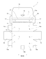
次に、図2~図5を用いて、本実施形態に係るフィルム収納容器1の構成について説明する。
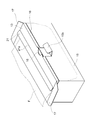
本実施形態に係るフィルム収納容器1は、フィルムFが巻回されてなるフィルム巻回体R(図3)を収納する収納空間10aを有する容器本体10と、容器本体10に形成された引出口20と、引出口20から容器本体10の外部へと引き出されたフィルムFを仮留めする仮留部30と、を備えている。なお、本フィルム収納容器1に収納されるフィルム巻回体RのフィルムFは、既に説明したように、切断起点部Sを起点として切断力が加えられた場合に、引出口20からの引出方向(流れ方向)に対して略直交する幅方向(図6)に沿って引き裂かれるとともに、幅方向の端部に切込みが設けられていないように構成されたものである。なお、フィルム収納容器1の容器本体10とフィルム巻回体Rとによって、本実施形態に係るフィルム収納体が構成される。
容器本体10は、前板11と、底板12と、天板13と、一対の側板14,14と、後板15と、を有し、略直方体状に形成されている。前板11の幅方向両端部及び後板15の幅方向両端部には、図2に示すように、側板14の内面に糊付けされる糊代部11a、15aが各々接続されている。図2に示すように、天板13と前板11と底板12と後板15とはこの順で接続されている。
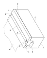
天板13の前板11と反対側の端部には、後板15の内面に重ねられるように差し込まれる後方差込片16が接続されている。また、天板13の幅方向両端部には、側板14の内面に重ねられるように差し込まれる側方差込片17が接続されている。さらに、天板13と後方差込片16との境界線Lの幅方向略中央部には、後板15に設けられた突出片15bを挿入させる切込部18が形成されている。
図2に破線で示した各境界線Lを山折りし、前板11及び後板15の糊代部11a、15aを側板14の内面に糊付けすることにより本体部を形成し、後方差込片16及び側方差込片17を本体部の内部空間に差し込んで各々後板15及び側板14の内面に重ね、図4に示すように突出片15bを切込部18に挿入することにより、略直方体状の容器本体10(図3)が形成される。突出片15b及び切込部18は、引出口20からフィルムFを引き出す際に天板13が本体部に対して浮き上がることを防止するとともに、長期間の使用に伴う天板13の沈み込みを防止する機構を構成する。なお、本実施形態における容器本体10には、フィルム巻回体RのフィルムFの切断を補助するための突起が設けられていない。
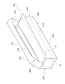
なお、本実施形態においては、天板13と後方差込片16との境界線Lの幅方向略中央部に切込部18を一つ設け、これに対応する突出片15bを後板15に設けた例を示したが、切込部及び突出片の位置や個数はこれに限定されるものではない。例えば、図5に示すように、天板13と一対の側方差込片17との境界線に各々切込部18を設け、これに対応する突出片14aを側板14に各々設けることもできる。
容器本体10の材質は、特に限定されず、例えば、プラスチック、金属、木材、ダンボール及び板紙、あるいはこれらの組み合わせ等が挙げられる。この中でも、厚さ2~3mmのダンボールを採用すると、容器本体10の大きさを比較的大きくしても剛性及び強度を確保することができるので好ましい。
引出口20は、容器本体10の収納空間10aに収納されたフィルム巻回体RのフィルムFを容器本体10の外部へと引き出すためのものである。本実施形態においては、容器本体10を構成する六面のうちの一面(天板13)に幅方向に沿って延在するように引出口20を形成している。なお、本実施形態においては、容器本体10の天板13に切込みを入れることにより、図3に示すように折曲線21aを中心に折曲する帯状の折曲部21を形成しており、折曲部21が上方に折曲することにより、引出口20が開くようになっている。
仮留部30は、引出口20から容器本体10の外部へと引き出されたフィルムFに対して粘着力を作用させてフィルムFを仮留めするものである。本実施形態においては、図2及び図3に示すように、容器本体10の一面(天板13)上の引出口20に近接した位置に、幅方向に沿って延在するように仮留部30を形成している。本実施形態における仮留部30は、引出口20から容器本体10の外部へと引き出されたフィルムFに対して粘着力を作用させる粘着部である。
粘着部(仮留部30)は、フィルム1に対して粘着力を作用させるものであればよい。例えば、架橋性硬化ニスを塗布し乾燥させて形成したニス塗布層で粘着部を構成することができる。架橋性硬化ニスとしては、例えばUV(紫外線)硬化ニスを採用することができる。UV硬化ニスの種類は特に限定されるものではなく、例えばラジカル重合型、付加重合型、カチオン重合型等を採用することができる。また、アクリル系やウレタン系の各種粘着剤(例えばUV架橋硬化性アクリル系エステル樹脂)により粘着部を構成することもできる。また、帯状の両面テープの一方の面を容器本体10の天板13に貼着し、この両面テープの他方の面を粘着部として機能させることもできる。なお、フィルムFに対して摩擦力を作用させる摩擦部を仮留部30として採用することもできる。摩擦部は、例えばゴム材料で構成することができる。
次に、図6を用いて、本発明の実施形態に係るフィルム収納容器1の使用方法(フィルムFの切断方法)について説明する。
まず、使用者は、フィルム収納容器1の容器本体10の収納部10aに収納されたフィルム巻回体RのフィルムFの引出方向端部を手で把持し、容器本体10の一面(天板13)に形成された引出口20から所定長引き出し、図6に示すように、引き出したフィルムFの下面に対して仮留部30により粘着力を作用させて、フィルムFを仮留めする。これにより、フィルムFが引出口20から引き出されるのを一時的に抑制することができる。
次いで、使用者は、図6に示すように、一方の手でフィルムFに張力を作用させた状態で、フィルムFの粘着力を作用させた部分よりも下流側にある切断起点部Sの一部を他方の手の指で突くことにより、貫通痕を形成する。これにより、フィルムFは、貫通痕を起点として幅方向に引き裂かれることとなる。
なお、幅方向端部に切込みが設けられたフィルムを採用すると、フィルムを引出口20から引き出す際や仮留部30に仮留めする際にフィルムに張力を作用させたときに、幅方向端部の切込みを起点としてフィルムが切れてしまう場合があるが、本実施形態におけるフィルムFは、引出しや仮留めの張力を作用させても幅方向端部の切込みを起点として切れてしまうことがない。また、幅方向端部に切込みが設けられたフィルムを採用すると、切込みがある箇所からしかフィルムを切ることができず、フィルムの使用量を自由に決めることができないが、本実施形態におけるフィルムFは引き裂く場所(貫通痕を形成する場所)を自由に決めることができ、ひいてはフィルムFの使用量を自由に決めることができるという利点がある。
以上説明した実施形態に係るフィルム収納容器1においては、引出口20から容器本体10の外部へと引き出されたフィルムFに対して仮留部30により粘着力を作用させることによりフィルムFを仮留めする(フィルムFが引出口20から引き出されるのを一時的に抑制する)ことができる。また、その状態において、フィルムFの粘着力を作用させた部分よりも下流側の部分に引裂力を加えることにより、フィルムFを幅方向に沿って引き裂くことができる。従って、フィルムFを切断するための刃やスライドカッタを用いることなく、手で容易にフィルムFを幅方向に沿って引き裂くことができる。このため、本フィルム収納容器1はきわめて安全なものとなり、本容器の廃棄時においては分別の手間を省くことができ、本容器の製作時においては手間やコストを低減させることができる。
また、以上説明した実施形態に係るフィルム収納容器1においては、略直方体状の容器本体10の一面(天板13)に形成された引出口20から引き出されたフィルムFに対し、引出口20に近接した位置で粘着力を作用させることができる。従って、弛みや歪みがなく引出方向がずれていない状態でフィルムFに引裂力を加えることができるので、フィルムFをきれいに引き裂くことができる。
また、以上説明した実施形態に係るフィルム収納容器1においては、容器本体10の天板13に設けた引出口20からフィルムFを引き出す際に、(前板11、底板12、側板14及び後板15によって形成される)本体部に対して天板13を固定することができる。従って、フィルムF引出し時における天板13の浮き上がりを防止することができるとともに、長期間の使用に伴う天板13の沈み込みを防止することができる。また、仮留部30によってフィルムFに作用させる粘着力が比較的強い場合であっても、天板13の浮き上がりを防止することができる。このため、粘着強度の高い仮留部30を採用することができるので、仮留部30をフィルムFに一層確実に密着させてフィルムFを引き裂き易くすることできる。また、使用回数を重ねたときに仮留部30の粘着力が弱くなって引き裂き難くなるという事態が生じることを回避することができる。
また、以上説明した実施形態に係るフィルムFにおいては、その幅方向の端部を除く部分(端部寄りの位置)に切断起点部Sが設けられているため、手で容易に切断することができる。幅方向の端部に切断起点部が設けられたフィルムを手で切断するためには、手首を大きく捻る必要がある(すなわち切断に大きな動作が必要となる)が、本実施形態のように幅方向の端部を除く部分に切断起点部Sが設けられたフィルムFは、比較的小さい動作で切断することが可能となる。また、フィルムの幅方向の端部に切断起点部が設けられていると、張力が作用したときにフィルムが幅方向の端部から切れてしまうという不測の事態が発生し得るが、本実施形態のようにフィルムFの幅方向の端部を除く部分に切断起点部Sが設けられていると、このような事態が発生することを防ぐことができる。また、フィルムの幅方向の端部に切断起点部が設けられていると、張力が作用したときにフィルムの幅方向の端部が変形して切断起点部として機能しない場合があるが、本実施形態のようにフィルムFの幅方向の端部を除く部分に切断起点部Sが設けられていると、張力が作用しても切断起点部Sの変形が少なくなるため、安定的に切断を開始することができる。
また、以上の実施形態においては、穿孔(貫通孔)Hを設けることにより切断起点部Sを形成した例を示したが、切断起点部の構成はこれに限られるものではない。例えば、図7に示すように、フィルムFの幅方向の端部寄りの位置に、流れ方向に沿って連続的にエンボス加工を施すことにより、所定幅の切断起点部Sを形成することもできる。このように切断起点部Sを非貫通構造とすることにより、フィルムFで被覆される物品(例えば食品)の乾燥を防止することができる。
また、エンボス加工を施す代わりに、ランダムな傷を付けてもよい。この際、傷の深さを、フィルムFの厚さの1~50%程度に設定することが好ましい。また、やすり状のもので削って弱くなった箇所を切断起点部とすることもできる。さらに、薬品処理や機械的加工を施すことによって、フィルムFの幅方向の端部寄りの位置に、所定幅で一定厚さを有する周囲より薄い帯状部分を形成し、この薄い帯状部分を切断起点部とすることもできる。
また、以上の実施形態においては、フィルムFの幅方向の端部寄りの位置に一列の切断起点部Sを形成した例を示したが、複数列(例えば図8に示すように三列)の切断起点部Sを形成することもできる。
また、以上の実施形態においては、容器本体10にフィルムFの切断を補助するための突起を形成する代わりに、フィルムFを仮留めする仮留部30を設けた例を示したが、容器本体10の構成はこれに限られるものではない。
例えば、図9に示すように、上部が開口した直方体の収納室20Aと、収納室20Aを覆う蓋体30Aと、を有する容器本体10Aを採用することができる。収納室20Aは、前板21Aと、底板22Aと、後板23Aと、側板24Aと、の各壁面で形成することができる。蓋体30Aは、後板23Aの上端縁から収納室20Aを覆う方向に接続して設けられた蓋板31Aと、蓋板31Aの前端縁から前板21Aを覆う方向に延出した掩蓋片32Aと、掩蓋片32Aの両脇に設けられた脇掩蓋片33Aと、の各壁面で形成することができる。そして、仮留部30を設ける代わりに、フィルム巻回体RのフィルムFの切断を補助するための突起を容器本体10Aに設けることができる。
容器本体10Aの材質は、特に限定されず、例えば、プラスチック、金属、木材、ダンボール及び板紙、あるいはこれらの組み合わせ等が挙げられる。この中でも、使い勝手が良い点で、板紙が好ましい。この板紙は、厚さ0.35~1.50mmの厚紙で、一般に肉厚のものほど剛性、強度が高く丈夫な容器本体10Aが得られる。厚さを0.35~0.80mmにすると、折り曲げ加工が容易となるためより好ましい。
図10(a)~(g)は、突起Pの形状の例を示すものである。突起Pを取り付ける位置は、フィルムFを容易に切断できる位置であれば特に制限はなく、例えば蓋体30Aの掩蓋片32Aの先端縁部等に設けることができる。突起Pの材質としては、特に限定されないが、例えば、乳酸系ポリマーなどの脂肪族エステル系ポリマーや芳香族エステル系ポリマーなどのエステル系ポリマー、エチレン系ポリマー、プロピレン系ポリマー、スチレン系ポリマー、アミド系ポリマーなどの高分子材料、その他にバルカナイズド紙、樹脂含浸硬化紙、砥粒、砥粒固着紙、ブリキなどが挙げられる。これのなかでも、循環型で環境に配慮できる乳酸系ポリマーがより好ましい。
また、仮留部30と、フィルム巻回体RのフィルムFの切断を補助するための突起Pと、の双方をフィルム収納容器に設けることもできる。例えば、図3及び図4に示したフィルム収納容器1を若干変形したフィルム収納容器1A(引出口20を突出片15b側に向けるとともに、仮留部30を突出片15b側に移動させたもの:図11参照)を採用し、突出片15bの左右二箇所に突起Pを配置することができる。突起Pとしては、長さ2~4cm程度のブリキ製の鋸刃を採用することができる。例えば図11に示すように、突出片15bに対応する部分を切り欠いた切欠部41を有する厚紙40の上端部の左右二箇所に突起Pを固定し、この厚紙40をフィルム収納容器1Aの内部(板15と差込片16との間)に差し込む、という手順により、突起Pを突出片15bの左右二箇所に配置することができる。
また、図12に示すように、天板13と一対の側方差込片17との境界線に各々切込部18を設け、これに対応する突出片14aを側板14に各々設けたフィルム収納容器1Bを採用してもよい。かかる場合には、図12に示すように、板15の上端部の全幅に亘って突起P(例えばブリキ製の鋸刃)を配置することができる。この際、図12に示すように、板15とほぼ同一形状の厚紙50の上端部に突起Pを固定し、この厚紙50をフィルム収納容器1Aの内部(板15と差込片16との間)に差し込む、という手順により、突起Pを板15の上端部の全幅に亘って配置することができる。
また、以上の実施形態においては、食品包装用のラップフィルムに本発明を適用した例を示したが、他の用途のフィルム(例えば医療用、農業用、梱包用等のフィルム)に本発明を適用することもできる。上記三例の用途用のフィルムに本発明を適用した場合には、フィルム巻回体Rを収容するための容器本体10(10A)を省くこともできる。
本発明は、以上の実施形態に限定されるものではなく、かかる実施形態に当業者が適宜設計変更を加えたものも、本発明の特徴を備えている限り、本発明の範囲に包含される。すなわち、前記実施形態が備える各要素及びその配置、材料、条件、形状、サイズ等は、例示したものに限定されるわけではなく適宜変更することができる。また、前記実施形態が備える各要素は、技術的に可能な限りにおいて組み合わせることができ、これらを組み合わせたものも本発明の特徴を含む限り本発明の範囲に包含される。
1・1A・1B…フィルム収納容器
10・10A…容器本体
10a…収納空間
11…前板
12…底板
13…天板(容器本体の一面)
14…側板
14a…突出片
15…後板
15b…突出片
16…後方差込片
18…切込部
20…引出口
20A…収納室
21A…前板
22A…底板
23A…後板
24A…側板
30…仮留部
30A…蓋体
31A…蓋板
32A…掩蓋片
33A…脇掩蓋片
F…フィルム
H…穿孔
P…突起
R…フィルム巻回体
S…切断起点部
10・10A…容器本体
10a…収納空間
11…前板
12…底板
13…天板(容器本体の一面)
14…側板
14a…突出片
15…後板
15b…突出片
16…後方差込片
18…切込部
20…引出口
20A…収納室
21A…前板
22A…底板
23A…後板
24A…側板
30…仮留部
30A…蓋体
31A…蓋板
32A…掩蓋片
33A…脇掩蓋片
F…フィルム
H…穿孔
P…突起
R…フィルム巻回体
S…切断起点部
Claims (20)
- フィルムの巻回体を収納する収納空間を有する容器本体と、前記収納空間に収納された前記巻回体の前記フィルムを前記容器本体の外部へと引き出すために前記容器本体に形成された引出口と、を備えるフィルム収納容器であって、
前記フィルムは、引裂力が加えられた場合に、前記引出口からの引出方向に対して略直交する幅方向に沿って引き裂かれるように構成され、
前記容器本体は、天板と、前板と、底板と、一対の側板と、後板と、を有し、
前記前板と前記底板と前記側板と前記後板とによって形成される本体部の内部空間に、前記天板を固定する突出片が挿入されるように構成されており、
前記引出口は、前記天板に設けられている、フィルム収納容器。 - 前記容器本体は、略直方体状に形成されてなり、
前記引出口は、前記容器本体を構成する六面のうちの一面に前記幅方向に沿って延在するように形成されており、
前記引出口から前記容器本体の外部へと引き出された前記フィルムに対して粘着力乃至摩擦力を作用させて前記フィルムを仮留めする仮留部を備え、
前記仮留部は、前記容器本体の前記一面上の前記引出口に近接した位置に前記幅方向に沿って延在するように形成されている、請求項1に記載のフィルム収納容器。 - 前記天板に設けられた切込部を備え、
前記突出片が前記切込部に挿入されるように構成されている、請求項2に記載のフィルム収納容器。 - 前記仮留部は、前記引出口から前記容器本体の外部へと引き出された前記フィルムに対して粘着力を作用させる粘着部である、請求項2又は3に記載のフィルム収納容器。
- 前記粘着部は、ニス塗布層で構成されている、請求項4に記載のフィルム収納容器。
- 前記粘着部は、両面テープで構成されている、請求項4に記載のフィルム収納容器。
- 前記仮留部は、前記引出口から前記容器本体の外部へと引き出された前記フィルムに対して摩擦力を作用させる摩擦部である、請求項2又は3に記載のフィルム収納容器。
- 前記摩擦部は、ゴム材料で構成されている、請求項7に記載のフィルム収納容器。
- 所定の流れ方向に沿って延在するように構成され、前記流れ方向に対して略直交する幅方向の端部を除く部分に切断起点部が設けられている、フィルム。
- ゲル分率が10~60重量%である、請求項9に記載のフィルム。
- 前記切断起点部は、少なくとも一つの穿孔である、請求項9又は10に記載のフィルム。
- 前記切断起点部は、エンボス加工が施された部分である、請求項9又は10に記載のフィルム。
- 前記切断起点部は、前記流れ方向に沿って連続的に設けられている、請求項9から12の何れか一項に記載のフィルム。
- 前記切断起点部は、前記幅方向の端部から25mm以上内側の位置に設けられている、請求項9から13の何れか一項に記載のフィルム。
- 前記切断起点部は、前記幅方向の略中央部に設けられている、請求項9から13の何れか一項に記載のフィルム。
- 請求項9から15の何れか一項に記載のフィルムが巻回されてなる、フィルム巻回体。
- 請求項16に記載のフィルム巻回体と、前記フィルム巻回体を収納する収納空間を有する容器本体と、を備えるフィルム収納体であって、
前記容器本体は、前記フィルム巻回体のフィルムの切断を補助するための突起を有している、フィルム収納体。 - 前記容器本体は、
前板と、底板と、後板と、側板と、の各壁面で形成される上部が開口した直方体の収納室と、
前記後板の上端縁から前記収納室を覆う方向に接続して設けられた蓋板と、前記蓋板の前端縁から前記前板を覆う方向に延出した掩蓋片と、前記掩蓋片の両脇に設けられた脇掩蓋片と、の各壁面で形成される蓋体と、を有し、
前記突起は、前記掩蓋片の先端縁部に設けられている、請求項17に記載のフィルム収納体。 - 請求項16に記載のフィルム巻回体と、前記フィルム巻回体を収納する収納空間を有する容器本体と、を備えるフィルム収納体であって、
前記容器本体は、前記フィルム巻回体のフィルムの切断を補助するための突起を有していない、フィルム収納体。 - 請求項9から15の何れか一項のフィルムの切断起点部の一部を手の指で突くことにより貫通痕を形成し、前記貫通痕を起点として前記フィルムを前記幅方向に引き裂く、フィルムの切断方法。
Priority Applications (4)
| Application Number | Priority Date | Filing Date | Title |
|---|---|---|---|
| JP2017519181A JPWO2016186026A1 (ja) | 2015-05-15 | 2016-05-13 | フィルム収納容器、フィルム、フィルム巻回体及びフィルム収納体 |
| EP16796419.6A EP3296221A4 (en) | 2015-05-15 | 2016-05-13 | Film storage container, film, film roll, and film storage body |
| US15/572,911 US20180134484A1 (en) | 2015-05-15 | 2016-05-13 | Film storage container, film, film roll, and film storage body |
| CN201680024409.4A CN107531364A (zh) | 2015-05-15 | 2016-05-13 | 薄膜收纳容器、薄膜、薄膜卷绕体以及薄膜收纳体 |
Applications Claiming Priority (4)
| Application Number | Priority Date | Filing Date | Title |
|---|---|---|---|
| JP2015099818 | 2015-05-15 | ||
| JP2015-099818 | 2015-05-15 | ||
| JP2015117652 | 2015-06-10 | ||
| JP2015-117652 | 2015-06-10 |
Publications (1)
| Publication Number | Publication Date |
|---|---|
| WO2016186026A1 true WO2016186026A1 (ja) | 2016-11-24 |
Family
ID=57320019
Family Applications (1)
| Application Number | Title | Priority Date | Filing Date |
|---|---|---|---|
| PCT/JP2016/064291 Ceased WO2016186026A1 (ja) | 2015-05-15 | 2016-05-13 | フィルム収納容器、フィルム、フィルム巻回体及びフィルム収納体 |
Country Status (5)
| Country | Link |
|---|---|
| US (1) | US20180134484A1 (ja) |
| EP (1) | EP3296221A4 (ja) |
| JP (1) | JPWO2016186026A1 (ja) |
| CN (1) | CN107531364A (ja) |
| WO (1) | WO2016186026A1 (ja) |
Families Citing this family (1)
| Publication number | Priority date | Publication date | Assignee | Title |
|---|---|---|---|---|
| US12344496B2 (en) * | 2021-08-26 | 2025-07-01 | Reynolds Consumer Products LLC | Containers, blanks, and methods for dispensing web material |
Citations (7)
| Publication number | Priority date | Publication date | Assignee | Title |
|---|---|---|---|---|
| JPS5694727U (ja) * | 1979-12-19 | 1981-07-28 | ||
| JPS6140317U (ja) * | 1984-08-16 | 1986-03-14 | 株式会社 日本エンジニアリングサ−ビス | ロ−ル状連続袋が収納してある紙箱 |
| JPH07256807A (ja) * | 1994-03-25 | 1995-10-09 | Seiji Kagawa | 易裂性積層フィルムおよびその製造方法 |
| JP2001246707A (ja) * | 2000-03-06 | 2001-09-11 | Asahi Kasei Corp | 架橋積層ラップフィルム |
| EP1270437A2 (en) * | 2001-06-29 | 2003-01-02 | Nuova Poliver di Oddone Colomba & C. S.n.c. | Food-packing film |
| JP2007176592A (ja) * | 2005-12-28 | 2007-07-12 | Daio Paper Corp | ロールシート用収納体及び収納体一体型ロールシート |
| JP2014005079A (ja) * | 2012-05-28 | 2014-01-16 | Kureha Corp | 包装容器 |
Family Cites Families (9)
| Publication number | Priority date | Publication date | Assignee | Title |
|---|---|---|---|---|
| US3974947A (en) * | 1973-06-13 | 1976-08-17 | The Dow Chemical Company | Dispensing carton for roll materials |
| US4179030A (en) * | 1978-11-24 | 1979-12-18 | Eltra Corporation | Unitary foldable dispenser reel and container with removable dispenser portion |
| US4651911A (en) * | 1986-03-10 | 1987-03-24 | Reynolds Metals Company | Roll material dispenser carton |
| JPH11124133A (ja) * | 1997-10-21 | 1999-05-11 | Asahi Chem Ind Co Ltd | ラップフィルム収納箱 |
| US6682808B2 (en) * | 2001-04-20 | 2004-01-27 | Asahi Kasei Kabushiki Kaisha | Crosslinked laminated wrap film and dispenser box therefor |
| US20050139626A1 (en) * | 2003-04-04 | 2005-06-30 | Owens John R. | Newsprint dispensing device |
| CN200942946Y (zh) * | 2006-08-09 | 2007-09-05 | 詹万均 | 防止保鲜膜回卷的盒体结构改良 |
| CN201037067Y (zh) * | 2006-12-17 | 2008-03-19 | 谢伟森 | 保鲜膜包装盒一体结构 |
| CN203512918U (zh) * | 2013-09-25 | 2014-04-02 | 郭家庆 | 一种带防滑条的滑刀剪切式保鲜膜盒 |
-
2016
- 2016-05-13 EP EP16796419.6A patent/EP3296221A4/en not_active Withdrawn
- 2016-05-13 WO PCT/JP2016/064291 patent/WO2016186026A1/ja not_active Ceased
- 2016-05-13 US US15/572,911 patent/US20180134484A1/en not_active Abandoned
- 2016-05-13 JP JP2017519181A patent/JPWO2016186026A1/ja active Pending
- 2016-05-13 CN CN201680024409.4A patent/CN107531364A/zh active Pending
Patent Citations (7)
| Publication number | Priority date | Publication date | Assignee | Title |
|---|---|---|---|---|
| JPS5694727U (ja) * | 1979-12-19 | 1981-07-28 | ||
| JPS6140317U (ja) * | 1984-08-16 | 1986-03-14 | 株式会社 日本エンジニアリングサ−ビス | ロ−ル状連続袋が収納してある紙箱 |
| JPH07256807A (ja) * | 1994-03-25 | 1995-10-09 | Seiji Kagawa | 易裂性積層フィルムおよびその製造方法 |
| JP2001246707A (ja) * | 2000-03-06 | 2001-09-11 | Asahi Kasei Corp | 架橋積層ラップフィルム |
| EP1270437A2 (en) * | 2001-06-29 | 2003-01-02 | Nuova Poliver di Oddone Colomba & C. S.n.c. | Food-packing film |
| JP2007176592A (ja) * | 2005-12-28 | 2007-07-12 | Daio Paper Corp | ロールシート用収納体及び収納体一体型ロールシート |
| JP2014005079A (ja) * | 2012-05-28 | 2014-01-16 | Kureha Corp | 包装容器 |
Non-Patent Citations (1)
| Title |
|---|
| See also references of EP3296221A4 * |
Also Published As
| Publication number | Publication date |
|---|---|
| JPWO2016186026A1 (ja) | 2017-11-16 |
| CN107531364A (zh) | 2018-01-02 |
| EP3296221A1 (en) | 2018-03-21 |
| EP3296221A4 (en) | 2018-10-31 |
| US20180134484A1 (en) | 2018-05-17 |
Similar Documents
| Publication | Publication Date | Title |
|---|---|---|
| US9139344B2 (en) | Packing tape | |
| US20090057172A1 (en) | Parallelepipedal Flexible Packaging With Breakable Zone | |
| JP2017145063A (ja) | 包装容器 | |
| JP2008280076A (ja) | フィルム分配ケースおよびフィルム入りケース | |
| EP1457424B1 (en) | Packaging for round-shaped biscuits | |
| WO2016186026A1 (ja) | フィルム収納容器、フィルム、フィルム巻回体及びフィルム収納体 | |
| JP6125922B2 (ja) | ラップフィルム装置 | |
| WO2017221514A1 (ja) | 収納容器用切断刃、および、収納容器 | |
| JP6891605B2 (ja) | 紙容器 | |
| KR102584904B1 (ko) | 외부 필름을 포함하는 용기 | |
| JP5584593B2 (ja) | 包装媒体収納容器および包装媒体供給具 | |
| KR101551155B1 (ko) | 랩핑재 절취기능을 갖는 케이스 | |
| JP2009292508A (ja) | ラップフィルム用収納箱 | |
| JP2018122877A (ja) | 巻回体用の包装箱及びその製造方法 | |
| JP6181262B2 (ja) | 巻回体収容箱及び巻回体入り収容箱 | |
| JP6165547B2 (ja) | ラップフィルム収納箱 | |
| JP6715287B2 (ja) | 収容箱、および、カートン | |
| JP2026042983A (ja) | 巻回体収容箱 | |
| JP2010042843A (ja) | 収納箱用付属装置 | |
| JP2018027807A (ja) | 収納箱 | |
| JPH0761450A (ja) | ラップフィルム用容器 | |
| JP5658554B2 (ja) | 包装媒体収納容器 | |
| JP6396530B2 (ja) | 巻回フィルム収納箱 | |
| JP6134229B2 (ja) | ラップフィルム収納箱及びラップフィルム収納箱の製造方法 | |
| JP2015034046A (ja) | ラップフィルム収納箱 |
Legal Events
| Date | Code | Title | Description |
|---|---|---|---|
| 121 | Ep: the epo has been informed by wipo that ep was designated in this application |
Ref document number: 16796419 Country of ref document: EP Kind code of ref document: A1 |
|
| ENP | Entry into the national phase |
Ref document number: 2017519181 Country of ref document: JP Kind code of ref document: A |
|
| WWE | Wipo information: entry into national phase |
Ref document number: 15572911 Country of ref document: US |
|
| NENP | Non-entry into the national phase |
Ref country code: DE |