WO2016189662A1 - Cathéter pour l'insertion dans un vaisseau sanguin ramifié - Google Patents
Cathéter pour l'insertion dans un vaisseau sanguin ramifié Download PDFInfo
- Publication number
- WO2016189662A1 WO2016189662A1 PCT/JP2015/065124 JP2015065124W WO2016189662A1 WO 2016189662 A1 WO2016189662 A1 WO 2016189662A1 JP 2015065124 W JP2015065124 W JP 2015065124W WO 2016189662 A1 WO2016189662 A1 WO 2016189662A1
- Authority
- WO
- WIPO (PCT)
- Prior art keywords
- catheter
- distal end
- change point
- property change
- physical property
- Prior art date
- Legal status (The legal status is an assumption and is not a legal conclusion. Google has not performed a legal analysis and makes no representation as to the accuracy of the status listed.)
- Ceased
Links
Images

Classifications
-
- A—HUMAN NECESSITIES
- A61—MEDICAL OR VETERINARY SCIENCE; HYGIENE
- A61M—DEVICES FOR INTRODUCING MEDIA INTO, OR ONTO, THE BODY; DEVICES FOR TRANSDUCING BODY MEDIA OR FOR TAKING MEDIA FROM THE BODY; DEVICES FOR PRODUCING OR ENDING SLEEP OR STUPOR
- A61M25/00—Catheters; Hollow probes
- A61M25/0043—Catheters; Hollow probes characterised by structural features
- A61M25/005—Catheters; Hollow probes characterised by structural features with embedded materials for reinforcement, e.g. wires, coils, braids
-
- A—HUMAN NECESSITIES
- A61—MEDICAL OR VETERINARY SCIENCE; HYGIENE
- A61M—DEVICES FOR INTRODUCING MEDIA INTO, OR ONTO, THE BODY; DEVICES FOR TRANSDUCING BODY MEDIA OR FOR TAKING MEDIA FROM THE BODY; DEVICES FOR PRODUCING OR ENDING SLEEP OR STUPOR
- A61M25/00—Catheters; Hollow probes
- A61M25/0021—Catheters; Hollow probes characterised by the form of the tubing
- A61M25/0023—Catheters; Hollow probes characterised by the form of the tubing by the form of the lumen, e.g. cross-section, variable diameter
-
- A—HUMAN NECESSITIES
- A61—MEDICAL OR VETERINARY SCIENCE; HYGIENE
- A61M—DEVICES FOR INTRODUCING MEDIA INTO, OR ONTO, THE BODY; DEVICES FOR TRANSDUCING BODY MEDIA OR FOR TAKING MEDIA FROM THE BODY; DEVICES FOR PRODUCING OR ENDING SLEEP OR STUPOR
- A61M25/00—Catheters; Hollow probes
-
- A—HUMAN NECESSITIES
- A61—MEDICAL OR VETERINARY SCIENCE; HYGIENE
- A61M—DEVICES FOR INTRODUCING MEDIA INTO, OR ONTO, THE BODY; DEVICES FOR TRANSDUCING BODY MEDIA OR FOR TAKING MEDIA FROM THE BODY; DEVICES FOR PRODUCING OR ENDING SLEEP OR STUPOR
- A61M25/00—Catheters; Hollow probes
- A61M25/0043—Catheters; Hollow probes characterised by structural features
- A61M25/0045—Catheters; Hollow probes characterised by structural features multi-layered, e.g. coated
-
- A—HUMAN NECESSITIES
- A61—MEDICAL OR VETERINARY SCIENCE; HYGIENE
- A61M—DEVICES FOR INTRODUCING MEDIA INTO, OR ONTO, THE BODY; DEVICES FOR TRANSDUCING BODY MEDIA OR FOR TAKING MEDIA FROM THE BODY; DEVICES FOR PRODUCING OR ENDING SLEEP OR STUPOR
- A61M25/00—Catheters; Hollow probes
- A61M25/0043—Catheters; Hollow probes characterised by structural features
- A61M25/005—Catheters; Hollow probes characterised by structural features with embedded materials for reinforcement, e.g. wires, coils, braids
- A61M25/0053—Catheters; Hollow probes characterised by structural features with embedded materials for reinforcement, e.g. wires, coils, braids having a variable stiffness along the longitudinal axis, e.g. by varying the pitch of the coil or braid
-
- A—HUMAN NECESSITIES
- A61—MEDICAL OR VETERINARY SCIENCE; HYGIENE
- A61M—DEVICES FOR INTRODUCING MEDIA INTO, OR ONTO, THE BODY; DEVICES FOR TRANSDUCING BODY MEDIA OR FOR TAKING MEDIA FROM THE BODY; DEVICES FOR PRODUCING OR ENDING SLEEP OR STUPOR
- A61M25/00—Catheters; Hollow probes
- A61M25/0043—Catheters; Hollow probes characterised by structural features
- A61M25/0054—Catheters; Hollow probes characterised by structural features with regions for increasing flexibility
-
- A—HUMAN NECESSITIES
- A61—MEDICAL OR VETERINARY SCIENCE; HYGIENE
- A61M—DEVICES FOR INTRODUCING MEDIA INTO, OR ONTO, THE BODY; DEVICES FOR TRANSDUCING BODY MEDIA OR FOR TAKING MEDIA FROM THE BODY; DEVICES FOR PRODUCING OR ENDING SLEEP OR STUPOR
- A61M25/00—Catheters; Hollow probes
- A61M25/01—Introducing, guiding, advancing, emplacing or holding catheters
- A61M25/0105—Steering means as part of the catheter or advancing means; Markers for positioning
- A61M25/0108—Steering means as part of the catheter or advancing means; Markers for positioning using radio-opaque or ultrasound markers
-
- A—HUMAN NECESSITIES
- A61—MEDICAL OR VETERINARY SCIENCE; HYGIENE
- A61M—DEVICES FOR INTRODUCING MEDIA INTO, OR ONTO, THE BODY; DEVICES FOR TRANSDUCING BODY MEDIA OR FOR TAKING MEDIA FROM THE BODY; DEVICES FOR PRODUCING OR ENDING SLEEP OR STUPOR
- A61M25/00—Catheters; Hollow probes
- A61M25/01—Introducing, guiding, advancing, emplacing or holding catheters
- A61M25/09—Guide wires
-
- A—HUMAN NECESSITIES
- A61—MEDICAL OR VETERINARY SCIENCE; HYGIENE
- A61M—DEVICES FOR INTRODUCING MEDIA INTO, OR ONTO, THE BODY; DEVICES FOR TRANSDUCING BODY MEDIA OR FOR TAKING MEDIA FROM THE BODY; DEVICES FOR PRODUCING OR ENDING SLEEP OR STUPOR
- A61M25/00—Catheters; Hollow probes
- A61M25/0021—Catheters; Hollow probes characterised by the form of the tubing
- A61M2025/0042—Microcatheters, cannula or the like having outside diameters around 1 mm or less
-
- A—HUMAN NECESSITIES
- A61—MEDICAL OR VETERINARY SCIENCE; HYGIENE
- A61M—DEVICES FOR INTRODUCING MEDIA INTO, OR ONTO, THE BODY; DEVICES FOR TRANSDUCING BODY MEDIA OR FOR TAKING MEDIA FROM THE BODY; DEVICES FOR PRODUCING OR ENDING SLEEP OR STUPOR
- A61M25/00—Catheters; Hollow probes
- A61M25/0043—Catheters; Hollow probes characterised by structural features
- A61M25/0045—Catheters; Hollow probes characterised by structural features multi-layered, e.g. coated
- A61M2025/0046—Coatings for improving slidability
-
- A—HUMAN NECESSITIES
- A61—MEDICAL OR VETERINARY SCIENCE; HYGIENE
- A61M—DEVICES FOR INTRODUCING MEDIA INTO, OR ONTO, THE BODY; DEVICES FOR TRANSDUCING BODY MEDIA OR FOR TAKING MEDIA FROM THE BODY; DEVICES FOR PRODUCING OR ENDING SLEEP OR STUPOR
- A61M25/00—Catheters; Hollow probes
- A61M25/0043—Catheters; Hollow probes characterised by structural features
- A61M25/0045—Catheters; Hollow probes characterised by structural features multi-layered, e.g. coated
- A61M2025/0046—Coatings for improving slidability
- A61M2025/0047—Coatings for improving slidability the inner layer having a higher lubricity
-
- A—HUMAN NECESSITIES
- A61—MEDICAL OR VETERINARY SCIENCE; HYGIENE
- A61M—DEVICES FOR INTRODUCING MEDIA INTO, OR ONTO, THE BODY; DEVICES FOR TRANSDUCING BODY MEDIA OR FOR TAKING MEDIA FROM THE BODY; DEVICES FOR PRODUCING OR ENDING SLEEP OR STUPOR
- A61M25/00—Catheters; Hollow probes
- A61M25/0043—Catheters; Hollow probes characterised by structural features
- A61M2025/0059—Catheters; Hollow probes characterised by structural features having means for preventing the catheter, sheath or lumens from collapsing due to outer forces, e.g. compressing forces, or caused by twisting or kinking
-
- A—HUMAN NECESSITIES
- A61—MEDICAL OR VETERINARY SCIENCE; HYGIENE
- A61M—DEVICES FOR INTRODUCING MEDIA INTO, OR ONTO, THE BODY; DEVICES FOR TRANSDUCING BODY MEDIA OR FOR TAKING MEDIA FROM THE BODY; DEVICES FOR PRODUCING OR ENDING SLEEP OR STUPOR
- A61M25/00—Catheters; Hollow probes
- A61M25/01—Introducing, guiding, advancing, emplacing or holding catheters
- A61M25/06—Body-piercing guide needles or the like
- A61M25/0662—Guide tubes
- A61M2025/0681—Systems with catheter and outer tubing, e.g. sheath, sleeve or guide tube
-
- A—HUMAN NECESSITIES
- A61—MEDICAL OR VETERINARY SCIENCE; HYGIENE
- A61M—DEVICES FOR INTRODUCING MEDIA INTO, OR ONTO, THE BODY; DEVICES FOR TRANSDUCING BODY MEDIA OR FOR TAKING MEDIA FROM THE BODY; DEVICES FOR PRODUCING OR ENDING SLEEP OR STUPOR
- A61M2205/00—General characteristics of the apparatus
- A61M2205/02—General characteristics of the apparatus characterised by a particular materials
- A61M2205/0216—Materials providing elastic properties, e.g. for facilitating deformation and avoid breaking
-
- A—HUMAN NECESSITIES
- A61—MEDICAL OR VETERINARY SCIENCE; HYGIENE
- A61M—DEVICES FOR INTRODUCING MEDIA INTO, OR ONTO, THE BODY; DEVICES FOR TRANSDUCING BODY MEDIA OR FOR TAKING MEDIA FROM THE BODY; DEVICES FOR PRODUCING OR ENDING SLEEP OR STUPOR
- A61M2210/00—Anatomical parts of the body
- A61M2210/10—Trunk
- A61M2210/1042—Alimentary tract
- A61M2210/1071—Liver; Hepar
-
- A—HUMAN NECESSITIES
- A61—MEDICAL OR VETERINARY SCIENCE; HYGIENE
- A61M—DEVICES FOR INTRODUCING MEDIA INTO, OR ONTO, THE BODY; DEVICES FOR TRANSDUCING BODY MEDIA OR FOR TAKING MEDIA FROM THE BODY; DEVICES FOR PRODUCING OR ENDING SLEEP OR STUPOR
- A61M25/00—Catheters; Hollow probes
- A61M25/0009—Making of catheters or other medical or surgical tubes
- A61M25/0012—Making of catheters or other medical or surgical tubes with embedded structures, e.g. coils, braids, meshes, strands or radiopaque coils
-
- A—HUMAN NECESSITIES
- A61—MEDICAL OR VETERINARY SCIENCE; HYGIENE
- A61M—DEVICES FOR INTRODUCING MEDIA INTO, OR ONTO, THE BODY; DEVICES FOR TRANSDUCING BODY MEDIA OR FOR TAKING MEDIA FROM THE BODY; DEVICES FOR PRODUCING OR ENDING SLEEP OR STUPOR
- A61M25/00—Catheters; Hollow probes
- A61M25/0021—Catheters; Hollow probes characterised by the form of the tubing
- A61M25/0041—Catheters; Hollow probes characterised by the form of the tubing pre-formed, e.g. specially adapted to fit with the anatomy of body channels
Definitions
- the present invention relates to a branched blood vessel insertion catheter for inserting into a small branch blood vessel branched from a mother blood vessel from the mother blood vessel.
- a catheter In the treatment of lesions using a catheter, for example, in the treatment of a liver, it may be required to insert the catheter into a small branched blood vessel that branches off from the mother blood vessel (liver artery).
- a procedure is performed in which a catheter is introduced along a guide wire that is inserted into a mother blood vessel and has a distal end reaching the branch blood vessel, and the distal end is inserted into the branch blood vessel.
- the distal end portion of the guide wire inserted into the branch vessel may be detached from the branch vessel due to the rigidity of the distal end portion of the catheter. It was.
- An object of the present invention is to insert the distal end of a catheter into a branch blood vessel along the guide wire inserted into the mother blood vessel and having the distal end reached the branch blood vessel.
- a branch blood vessel insertion catheter that can easily and surely insert the distal end portion of the catheter into the branch blood vessel without detachment from the branch blood vessel.
- a branched blood vessel insertion catheter for inserting the first blood vessel and the branched blood vessel branched from the first blood vessel into the branched blood vessel through the branch from the first blood vessel,
- a catheter body having a lumen communicating from a distal end to a proximal end for insertion of a guide wire, the catheter body comprising an inner layer, a wire winding reinforcement provided on an outer surface of the inner layer, the inner layer, and the inner layer;
- An outer layer covering the reinforcing body, and the catheter body includes a first physical property change point located at 3.0 to 7.0 mm from the distal end of the catheter, and before and after the first physical property change point.
- a branch vessel insertion catheter having a proximal end side that is higher in rigidity than the distal end side.
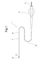
- FIG. 1 is a partially omitted external view showing a state in which a guide wire is inserted through a branch vessel insertion catheter according to an embodiment of the present invention.
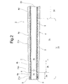
- FIG. 2 is an enlarged cross-sectional view of a distal end portion of the branch vessel insertion catheter shown in FIG.
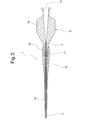
- FIG. 3 is an enlarged cross-sectional view of a proximal end portion of the branch vessel insertion catheter shown in FIG.
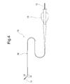
- FIG. 4 is a partially omitted external view showing a state in which a guide wire is inserted through a branch vessel insertion catheter according to another embodiment of the present invention.
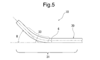
- FIG. 5 is an enlarged external view of the distal end portion of the branch vessel insertion catheter shown in FIG. FIG.
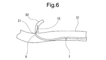
- FIG. 6 is an explanatory view for explaining the action of the branch vessel insertion catheter of the present invention.
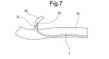
- FIG. 7 is an explanatory view for explaining the operation of the branch vessel insertion catheter of the present invention.
- FIG. 8 is an explanatory diagram for explaining the operation of a conventional branch vessel insertion catheter.
- the catheter of the present invention will be described with reference to the embodiments shown in the drawings.
- the branch blood vessel insertion catheter of the present invention is inserted into the branch blood vessel 52 through the first blood vessel 51 and the small branch blood vessel 52 branched from the first blood vessel 51 through the branch.
- This is a bifurcated blood vessel insertion catheter.
- the branch vessel insertion catheter 1 has a catheter body 2 having a lumen 20 communicating from the distal end to the proximal end for insertion of a guide wire 15.
- the catheter body 2 is provided on the inner layer 3 and the outer surface of the inner layer 3.
- the wire wound reinforcing body 5 and the inner layer 3 and the outer layer 4 covering the reinforcing body 5 are provided.
- the catheter body 2 includes a first physical property change point 6 located 3.0 to 7.0 mm from the distal end of the catheter 1, and the proximal end side is more rigid than the distal end side before and after the first physical property change point 6. Is expensive. An easy-bending portion is formed by the first physical property change point 6 portion.
- the branch vessel insertion catheter 1 of the present invention branches from a first blood vessel (hepatic artery) into a first blood vessel (for example, a hepatic artery) and a narrow branch blood vessel that branches from the first blood vessel (hepatic artery). It is a catheter for branch blood vessel insertion for passing through and inserting into a branch blood vessel.
- the bifurcated blood vessel insertion catheter 1 of the present invention is particularly effective when applied to a microcatheter having an outer diameter of the tip of 1.0 mm or less. Furthermore, it is more effective when applied to a microcatheter having an outer diameter of 0.7 mm or less.
- the branch vessel insertion catheter 1 includes a catheter body 2 having a lumen 20 penetrating from the distal end to the proximal end, and a hub 11 fixed to the proximal end of the catheter body 2.
- the catheter body 2 includes an inner layer 3, a wire-wrapped reinforcing body 5 provided on the outer surface of the inner layer 3, and an outer layer 4 that covers the inner layer 3 and the reinforcing body 5.
- the catheter body 2 includes a first physical property change point 6 located 3.0 to 7.0 mm from the distal end of the catheter 1, and the proximal end side is more rigid than the distal end side before and after the first physical property change point 6.
- a bendable part is formed at the site of the catheter body 2 located before and after the first physical property change point 6.
- the easy bending portion is a portion that tends to be the center of bending compared to before and after the first physical property change point 6.
- the easy bending portion means not a bending point but a region that is easily bent and formed before and after the first physical property change point 6.
- the catheter 1 In having such an easily bendable portion, when the distal end surface or the distal side portion of the catheter 1 comes into contact with the inner wall of the blood vessel in a state where the guide wire having the distal end entered the branch blood vessel is inserted through the catheter, the catheter 1 Is bent at the first physical property change point 6 located 3.0 to 7.0 mm from the distal end, so that the distal end of the catheter 1 jumps and leaves the distal end portion of the guide wire that has entered the branch blood vessel. I will not let you.
- the wire wound reinforcing body 5 has a first winding extending from the distal end of the catheter body 2 to the proximal end side beyond the first physical property change point 6.
- the outer layer 4 extends from the distal end of the catheter body 2 and includes a first resin forming portion 4a formed of the first resin, and the proximal end of the first resin forming portion 4a.
- a second resin forming portion 4b is provided that extends to the base end side and is formed of a second resin that is harder than the first resin.
- the 1st physical property change point 6 is formed of the boundary part of the 1st resin formation part 4a and the 2nd resin formation part 4b. Therefore, the boundary portion is located at 3.0 to 7.0 mm from the distal end of the catheter 1. In particular, the boundary portion is preferably located at 4.0 to 6.0 mm, more preferably 4.5 to 5.5 mm from the distal end of the catheter 1.
- the catheter body 2 will be specifically described.
- the catheter body 2 includes a distal end portion 21 and a main body portion 22.
- the catheter body 2 includes an inner layer 3 that extends throughout, an outer layer 4, and a reinforcing body 5.
- the inner layer 3 forms the inner lumen 20 for inserting the guide wire and the inner surface of the catheter body 2, and is made of substantially the same thickness from the distal end to the proximal end by the same material. It extends.
- the inner layer 3 includes a tip end inner diameter portion 3a extending from the tip to a portion slightly exceeding the first physical property change point 6, and a tip end inner diameter taper portion 3b extending from the base end of the tip end inner diameter portion 3a to the base end side by a predetermined length. And a base end side same inner diameter portion extending from the base end to the base end of the tip end inner diameter tapered portion 3b with substantially the same outer diameter.
- the inner diameter portion 3a having the same inner diameter at the tip of the inner layer 3 preferably has an inner diameter of 0.35 to 0.50 mm, particularly preferably 0.40 mm to 0.46 mm.
- the axial length of the inner diameter portion 3a of the inner layer 3 is preferably 5 to 10 mm
- the proximal end of the inner diameter portion 3a of the inner layer 3 has a base end from the first physical property change point 6. It is preferably located on the base end side of 0 to 4.0 mm.
- the inner diameter taper portion 3b on the distal end side of the inner layer 3 has an inner diameter at the distal end substantially equal to the inner diameter portion 3a with the same distal end, and an inner diameter at the proximal end of 0.53 to 0.65 mm, and is gentle toward the proximal end from the distal end.
- the diameter is preferably increased in a tapered shape.
- the axial length of the inner diameter side tapered portion 3b of the inner layer 3 is preferably about 60 to 200 mm, and more preferably 70 to 150 mm.
- the thickness of the inner layer 3 is preferably about 0.003 to 0.1 mm, and more preferably 0.005 to 0.05 mm.
- the inner layer 3 is formed from the same material to the proximal end.
- a material for forming the inner layer 3 fluororesins such as PTFE and ETFE, polyimide, polyester (for example, polyethylene terephthalate, polybutylene terephthalate), polyolefin (for example, ultra-high molecular polyethylene, polypropylene), polyamide, polyimide, modified polyethylene ether polyamide Rigid resins such as imide, polyetherimide, polystyrene sulfide, and liquid crystal polymer) are preferable.
- fluorine-based polymers such as PTFE and ETFE that can form a low friction inner surface are preferable.
- the wire wound reinforcing body 5 is formed by winding a wire around the outer surface of the inner layer 3.
- the wire-wound reinforcement 5 is preferably one that is wound around the outer surface of the inner layer in a mesh shape or a spiral shape with a thin wire made of a metal wire.
- the wire wound reinforcing body 5 is preferably constituted by a mesh braid (blade) in which thin wires are interwoven.
- a plurality of small-diameter wires wound in the first spiral direction at intervals in the axial direction of the inner layer 3, and the first spiral direction at intervals in the axial direction of the inner layer 3; is preferably a braid formed by crossing a plurality of small-diameter wires wound in different second spiral directions.
- a metal wire is suitable, for example, an X-ray contrasting metal wire such as stainless steel wire, amorphous alloy wire, platinum, gold, tungsten, tantalum, iridium, etc. is preferred.
- an amorphous alloy wire an amorphous alloy wire formed using an iron-silicon-boron alloy, a cobalt-silicon-boron alloy, an iron-cobalt-chromium-molybdenum-silicon-boron alloy, or the like is preferable.
- Tungsten is suitable as the X-ray contrast metal wire.
- a wire having a wire diameter of about 0.01 to 0.05 mm is preferable.
- the wire winding reinforcement body 5 includes a first winding condition portion extending from the distal end of the catheter body 2 to the proximal end side beyond the first physical property change point 6.
- the first winding condition portion extends in the proximal direction beyond a second property change point 7 described later.
- the wire to be used, the winding pitch of a wire, and the winding form of a wire are the same.
- the first winding condition portion exceeds the third resin forming portion 4d extending from the proximal end of the second resin forming portion 4c of the catheter to the proximal end side, and further, the proximal end. It extends to the side.
- the wire winding pitch in the first winding condition portion is preferably 0.2 to 0.8 mm, and particularly preferably 0.3 to 0.6 mm.
- the outer layer 4 extends from the distal end to the proximal end of the catheter body to form the outer surface form of the catheter body.
- the catheter body 2 has the same outer diameter portion 2a extending from the tip to the first physical property change point 6 and an outer diameter larger than the same outer diameter portion 2a (in other words, thicker in thickness), A second distal end identical outer diameter portion 2b extending from the proximal end of the distal end identical outer diameter portion 2a to a predetermined length proximal end side is provided.
- the 1st physical-property change point 6 is formed of the boundary part of the 1st resin formation part 4a and the 2nd resin formation part 4b.
- This boundary part is also an outer diameter changing part.
- the first physical property change point 6 is formed by a change in outer diameter and a difference in hardness of the forming material.
- the first physical property change point 6 is located at 3.0 to 7.0 mm from the distal end of the catheter 1.
- the three-point bending load of the proximal end portion 21b (second identical outer diameter portion 2b) of the catheter near the first physical property change point 6 is 3 of the distal end side portion 21a (the same outer diameter portion 2a of the distal end portion). It is preferably 1.5 to 2.5 times the point bending load. In particular, it is preferably 1.7 to 2.3 times.
- the “three-point bending load” here can be measured as follows. A measuring tool comprising a jig having a horizontal placement surface with a gap of 3 mm that opens upward, and a presser having a linear portion extending in the horizontal direction at the distal end portion, formed of a wire having a wire diameter of 0.85 mm Prepare.
- the catheter is placed on the horizontal placement surface of the jig so as to pass above the gap, and the measurement target part is positioned in the gap.
- the “three-point bending load” is obtained when the measurement target part is pushed into the measurement target part at a speed of 5 mm / min and 0.3 mm by a linear part extending in the horizontal direction from above (the measurement target part). Can be obtained by measuring the load).
- the three-point bending load of the tip side portion 21a near the first physical property change point 6 is preferably 8 to 15 gf, and particularly preferably 9 to 13 gf. Further, the three-point bending load of the proximal end portion 21b in the vicinity of the first physical property change point 6 is preferably 16 to 25 gf, and particularly preferably 18 to 23 gf.
- the three-point bending load at the first physical property change point 6 is preferably near the median value of the three-point bending load of the distal end portion 21a and the three-point bending load of the proximal end portion 21b. Specifically, the three-point bending load at the first physical property change point 6 is preferably 12 to 18 gf.
- the first physical property change point 6 has an axial length of 2.0 mm or less, and has a gradually increasing rigidity toward the base end side.
- the first physical property change point 6 preferably has an axial length of 0.5 to 2.0 mm, and more preferably 0.5 to 1.5 mm.
- the outer diameter of the first distal end portion identical outer diameter portion 2a of the catheter body 2 is preferably 0.50 to 0.65 mm, and particularly preferably 0.52 mm to 0.62 mm.
- the axial length of the first distal end portion identical outer diameter portion 2a of the catheter body 2 is preferably 3.0 to 7.0 mm, more preferably 4.0 to 6.0 mm, and more preferably Preferably, it is 4.5 to 5.5 mm.
- the wall thickness of the first tip portion and the same outer diameter portion 2a is preferably about 0.1 to 0.2 mm.
- the outer diameter of the second distal end identical outer diameter portion 2b of the catheter body 2 is preferably 0.55 to 0.70 mm, particularly preferably 0.57 mm to 0.65 mm. Further, the second tip end same outer diameter portion 2b is preferably 0.01 to 0.07 mm larger than the first tip end same outer diameter portion 2a, and particularly 0.02 to 0.05 mm. Larger is preferred.
- the wall thickness of the second tip portion identical outer diameter portion 2b is preferably about 0.05 to 0.15 mm. Moreover, it is preferable that the thickness of the 2nd front-end
- the axial length of the second tip end same outer diameter portion 2b is preferably 5.0 to 15.0 mm, and particularly preferably 7.0 to 13.0 mm.
- the second resin one having a higher hardness than the first resin is used.
- the first resin and the second resin are preferably different in hardness difference (for example, flexural modulus ASTM D790) by 4 to 15 MPa, and particularly preferably 5 to 10 MPa.
- the catheter body 2 includes the second physical property change point 7 located at 12.0 to 18.0 mm from the distal end of the catheter 1, and before and after the second physical property change point 7.
- the proximal end side has higher rigidity than the distal end side, and the second easily bent portion is formed before and after the second property change point 7.
- the second physical property change point 7 is located closer to the base end side than the first physical property change point 6.
- the second easily bent portion is a portion that tends to be the center of bending compared to before and after the second property change point 7.
- the second easily bent portion means not a bending point but a region that is easily bent and formed before and after the second physical property change point 7.
- the catheter 1 By having the second physical property change point 7 as described above, the proximal end side of the first physical property change point 6 of the catheter 1 in the state where the guide wire whose distal end has entered the small-diameter branch blood vessel is inserted through the catheter.
- the catheter 1 When the adjacent portion comes into contact with the inner wall of the blood vessel (for example, in the vicinity of the portion facing the blood vessel bifurcation), the catheter 1 is in close proximity to the first physical property change point 6 and the second physical property located on the proximal end side. Since it bends at the change point, it becomes easy to point the tip of the catheter 1 toward the blood vessel bifurcation, and after the tip of the catheter 1 enters the branch blood vessel, its state is secured. It becomes.
- the outer layer 4 has the second resin forming portion 4b formed of the above-described second resin.
- the catheter body 2 has a starting end having an outer diameter larger than that of the second distal end portion and the same outer diameter portion 2b, and has a larger outer diameter than the second distal end portion and the same outer diameter portion 2b.
- a distal end outer diameter taper portion 2c is provided that extends to the proximal end side by a predetermined length from (the proximal end of the second distal end same outer diameter portion 2b).
- the second physical property change point 7 has an axial length of 2.0 mm or less and has a gradually increasing rigidity from the distal end side toward the proximal end side.
- the second physical property change point 7 preferably has an axial length of 0.5 to 2.0 mm, and more preferably 0.5 to 1.5 mm.
- the distal end portion 21 of the catheter body 2 is located after the first distal end portion same outer diameter portion 2a and the first distal end portion same outer diameter portion 2a.
- a second distal end identical outer diameter portion 2b extending from the end in the proximal direction and having a larger diameter than the first distal end identical outer diameter portion 2a, and a rear end of the second distal end identical outer diameter portion 2b.
- a distal end side outer diameter taper portion 2c extending in the end direction and having a starting end larger than the second distal end same outer diameter portion 2b is provided.
- the first physical property change point 6 is located at the boundary between the first tip end same outer diameter portion 2a and the second tip end same outer diameter portion 2b, and the second physical property change point 7 is 2 is located at the boundary between the tip end outer diameter portion 2b and the tip end outer diameter taper portion 2c.
- the outer layer 4 includes a distal-end-side outer diameter taper portion 2c formed in the second resin forming portion 4b, and the second physical property change point 7 is formed by the start end of the enlarged-diameter portion. Yes.
- the difference in outer diameter before and after the second physical property change point 7 is preferably 0.02 to 0.05 mm.
- the three-point bending load of the proximal end portion 21c in the vicinity of the second property change point 7 is the distal end portion in the vicinity of the second property change point 7 (the proximal end portion in the vicinity of the first property change point 6). It is preferably 1.15 to 1.8 times the three-point bending load of 21b. In particular, it is preferably 1.2 to 1.6 times.
- the three-point bending load of the proximal end portion 21c near the second physical property change point 7 is preferably 20 to 45 gf, and particularly preferably 22 to 35 gf. Further, the three-point bending load of the tip end portion 21b in the vicinity of the second physical property change point 7 is preferably 16 to 25 gf, and particularly preferably 18 to 23 gf.
- the three-point bending load at the second property change point 7 is preferably near the median value of the three-point bending load of the distal end portion 21b and the three-point bending load of the proximal end portion 21c. Specifically, the three-point bending load at the second property change point 6 is preferably 20 to 26 gf.
- the second physical property change point 7 (in other words, the enlarged diameter portion) is located at 12.0 to 18.0 mm from the distal end of the catheter 1.
- the second physical property change point 7 (expanded portion) is preferably located at 13.0 to 17.0 mm from the distal end of the catheter 1.
- the second physical property change point 7 (expanded diameter portion) is preferably located 7.0 to 13.0 mm proximal to the first physical property change point 6. In particular, it is preferably located on the base end side of 9.0 to 11.0 mm.
- the distal end outer diameter taper portion 2c of the catheter body 2 has an outer diameter of 0.60 to 0.70 mm at the start end, and expands in a gentle taper shape from the start end to the base end. Is preferred.
- the outer diameter of the leading end of the outer diameter taper portion 2c on the distal end side is preferably 0.02 to 0.07 mm larger than the outer diameter (the outer diameter of the proximal end) of the same outer diameter portion 2b of the second distal end. In particular, it is preferably 0.03 to 0.06 mm larger.
- the thickness of the starting end of the distal end side outer diameter tapered portion 2c is preferably about 0.07 to 0.17 mm, and particularly preferably 0.08 to 0.14.
- the thickness of the distal end side outer diameter tapered portion 2c is preferably 0.005 mm or more thicker than the thickness of the second distal end same outer diameter portion 2b.
- the axial length of the distal end side outer diameter tapered portion 2c is preferably 30 to 100 mm, and particularly preferably 40 to 80 mm. Further, it is preferable that the outer diameter of the terminal end side outer diameter taper portion 2c is 0.65 to 0.75 mm.
- the outer diameter at the end of the tip-side outer diameter taper portion 2c is preferably 0.03 to 0.12 mm larger than the outer diameter of the starting end, and particularly preferably 0.05 to 0.10 mm larger.
- the length from the distal end to the proximal end of the distal outer diameter taper portion 2c is preferably 70 to 200 mm, and particularly 80 to 150 mm. It is preferable that
- tip part 21 of the catheter main body 2 is provided with the uniform inner diameter part 21a and the inner diameter taper part 21b extended in a base end direction from the rear end of the uniform inner diameter part 21a, and expanding the diameter. It has become a thing.
- the first physical property change point 6 described above is located at the uniform inner diameter portion 21a, and the second physical property change point 7 described above is located at the tip of the inner diameter taper portion 21b.
- the second resin forming portion 4c is made of a third resin having a hardness higher than that of the second resin and is closer to the proximal end than the second resin forming portion 4c.
- a third resin forming portion 4d extending from the base end of 4c to the base end side by a predetermined length is provided.
- the third resin forming portion 4d forms an intermediate outer diameter tapered portion 2d.
- the intermediate outer diameter tapered portion 2d has a starting end having the same outer diameter as the outer diameter of the end of the distal end side outer diameter tapered portion 2c, and is continuous with the distal end side outer diameter tapered portion 2c without a step.
- thermoplastic elastomer As a material for forming the outer layer 4, a thermoplastic elastomer is preferable.
- the thermoplastic elastomer include polyester elastomer (for example, polyethylene terephthalate elastomer), nylon elastomer (for example, polyamide elastomer), urethane elastomer (for example, polyurethane elastomer), olefin elastomer (for example, polyethylene elastomer, polypropylene elastomer), A fluororesin elastomer or the like is used.
- a thermoplastic polyester elastomer is suitable.
- thermoplastic polyester elastomer Perprene (registered trademark) P30B, P40B, P40H, P55B, P70B manufactured by Toyobo Co., Ltd., P90B, P150B, E450B, Hytrel (registered trademark) manufactured by Toray DuPont Co., Ltd. 3548W, 4047W, etc. are mentioned.
- the polyamide elastomer include Pevax (registered trademark) 533 SAOO, 3533 SAOO, 4033 SAOO and the like manufactured by Toray Industries, Inc.
- polyurethane elastomer include E380, E385, E390 and the like manufactured by Nippon Milactolan Co., Ltd. And as a 1st resin, a 2nd resin, and also as a 3rd resin, it is preferable to use what is different in hardness by the same system
- the catheter of the present invention is located on the distal end side from the first physical property change point 6 like the catheter 10 of the embodiment shown in FIGS. 4 and 5, and further has a bending angle with respect to the central axis of the catheter body 30. , 15 to 75 degrees may be provided.
- the bending angle of the bending portion 33 is more preferably 30 to 60 degrees.
- the bending portion 33 is preferably provided in the distal end portion 31 and at an intermediate portion between the distal end of the catheter 10 and the first physical property change point 6 or a position closer to the first physical property change point 6 than the intermediate portion. .
- the front end side from the curved part 33 is a straight part.
- the curved portion 33 is provided on the distal end side with respect to the first physical property change point 6 to easily enter the blood vessel branching portion, and the first physical property change point 6 or the first physical force is applied by the force applied to the distal end portion 21 of the catheter 10. Bending can be brought about before and after the physical property change point 6.
- the catheter body 2 includes a contrast marker 9 provided so as to encapsulate the distal end of the wire wound reinforcement 5.
- the contrast marker 9 is preferably formed of a radiopaque material (for example, gold, platinum, tungsten, or an alloy thereof, or a silver-palladium alloy, a platinum-iridium alloy, or the like).
- the catheter body 2 has the distal end 8 formed by the distal end portion of the first resin forming portion 4a.
- the tip 8 portion is composed only of the inner layer 3 and the outer layer 4, and the reinforcing body 5 and the marker 9 are portions that do not exist.
- the distal end portion of the inner layer 3 not having the reinforcing body 8 and the marker is formed, and the distal end 8 covers the inner layer 3 of this portion.
- the axial length of the tip 8 having no reinforcing body and marker is preferably about 0.1 to 0.5 mm.
- the hub 11 is fixed to the proximal end of the catheter body 2.
- the hub 11 has a shape and a structure as shown in FIGS. Specifically, the hub 11 has a tubular main body 14 having a penetrating internal passage and two wings on the side, and provided at the distal end of the main body 14.
- the cylindrical tip part 17 which accommodates and the connection part 13 provided in the rear end of the main-body part 14 are provided.
- the connecting portion 13 can be attached with suction means such as a syringe.
- the catheter 1 of this embodiment includes a kink preventing tube 12 provided so as to cover the rear end portion of the catheter body 2.
- the kink preventing tube 12 includes a rear portion 18 that covers the cylindrical distal end portion 17 of the hub 11, and a small diameter distal end portion 19 that encloses the proximal end portion of the catheter body 2 that protrudes from the main body portion 14 of the hub 11. Have.
- the distal end portion 19 of the kink prevention tube 12 is in close contact with the outer surface of the proximal end portion of the catheter body 2.
- the outer surface and the distal end surface of the outer layer 4 are subjected to treatment for exhibiting lubricity.
- treatment include polyhydroxyethyl methacrylate, polyhydroxyethyl acrylate, hydroxypropyl cellulose, methyl vinyl ether maleic anhydride copolymer, polyethylene glycol, polyacrylamide, polyvinyl pyrrolidone, dimethylacrylamide-glycidyl methacrylate copolymer, etc. And a method of coating or fixing the hydrophilic polymer.
- the operation method of the branch vessel insertion catheter 1 of the present invention will be described with reference to FIGS. 6 to 8, taking insertion of a hepatic artery into a branch vessel as an example.
- the guide wire 15 is inserted into the hepatic artery mother blood vessel 51, and the distal end portion is inserted into the branch blood vessel 52.
- the catheter 1 is inserted into the hepatic artery mother blood vessel 51 so that the guide wire 15 is encapsulated, and further, the distal end portion thereof is inserted near the opening of the branch blood vessel 52.
- the distal end portion of the catheter 1 abuts against the inner wall of the branch blood vessel 52 as shown in FIG.
- the catheter 1 can easily move in the proximal direction at the first property change point 6. Bend. Since the repulsive force in the distal direction in the bent state is small, the guide wire 15 is not separated from the branch blood vessel 52. Then, by further pushing in, the entire distal end portion 21 of the catheter 1 is inserted into the branch blood vessel 52 as shown in FIG.
- the distal end portion 101 of the catheter 100 is inserted in the vicinity of the opening of the branch blood vessel 52 and is bent.
- the tip portion of 100 generates a repulsive force in the tip direction.
- the distal end portion of the catheter 100 is pressed against the inner wall of the branch blood vessel and is more likely to be detached from the branch blood vessel.
- the guide wire 15 is also likely to be detached from the branch blood vessel. .
- Example 1 A tip portion having a diameter of 0.43 mm and a length of 20 mm; a taper portion having a base end diameter of 0.58 mm extending from the base end of the tip portion; and a base end side of the taper portion of 1600 mm
- a mandrel (core material) of a silver-plated annealed copper wire provided with a main body portion having a diameter of 0.58 mm extending in the middle is prepared.
- core material polytetrafluoroethylene was coated and formed to form an inner layer having a thickness of 0.01 mm on the outer peripheral surface of the mandrel.
- the outer surface of the inner layer was subjected to chemical treatment with a solution composed of a glycolic solvent, a solute of a Na salt of a naphthalene complex.
- a solution composed of a glycolic solvent, a solute of a Na salt of a naphthalene complex was cut, and the total length was adjusted to 1650 mm.
- a tungsten metal wire having a diameter of 0.018 mm is wound around the outer periphery at a pitch of 300 mm at a pitch of 0.4 mm, and then the pitch is gradually changed to 1.6 mm. And wound to form a wire wound reinforcement.
- a reinforcing body was formed on the inner layer and its outer peripheral portion, and a thin-walled annular (axial length 0.5 mm) contrast marker made of tungsten iridium alloy was fixed to the tip of the reinforcing body.
- a cylindrical first tube having an outer diameter of 0.57 mm and a length of 5 mm was prepared in advance.
- a thermoplastic polyester elastomer [bending elastic modulus (ASTM D790) 15 MPa, Perprene (registered trademark) P30B, manufactured by Toyobo Co., Ltd.] was used.
- a second tube having a front portion having an outer diameter of 0.61 mm and a length of 10 mm and a taper portion having an outer diameter of 0.64 mm and an outer diameter of 0.71 mm and a length of 35 mm was produced.
- a thermoplastic polyester elastomer [bending elastic modulus (ASTM D790) 23 MPa, Perprene (registered trademark) P40B, manufactured by Toyobo Co., Ltd.] was used.
- a third tube having an outer diameter of 0.65 mm and an outer diameter of 0.74 mm, a tapered portion having a length of 60 mm, and a proximal end portion extending to the proximal end of 140 mm with an outer diameter of 0.80 mm.
- a thermoplastic polyester elastomer [flexural modulus (ASTM D790) 108 MPa, Perprene (registered trademark) P40B, manufactured by Toyobo Co., Ltd.] was used.
- a fourth tapered tube having a length that increased from an outer diameter of 0.85 mm to an outer diameter of 0.94 mm and reached the proximal end of the catheter base material was produced.
- a thermoplastic polyester elastomer [Perprene (registered trademark), manufactured by Toyobo Co., Ltd.] having a higher flexural modulus (ASTMASTD790) than the third resin was used.
- the first tube, the second tube, the third tube, and the fourth tube were placed on the catheter base provided with the inner layer, the reinforcing body, and the marker so as to be in that order from the distal end side.
- the outer surface was covered with a heat shrinkable tube (FEP) made of a fluororesin, and both ends were fixed with stoppers. And it passed through the 340 degreeC heat tunnel, and the 1st tube, the 2nd tube, the 3rd tube, and the area
- FEP heat shrinkable tube
- a tetrahydrofuran (THF) solution of diphenylmethyl-diisocyanate adjusted to 5.3% was applied to the outer surface of the catheter body and dried at room temperature for 30 minutes.
- a THF solution of methyl vinyl ether maleic anhydride ethyl ester copolymer (hydrophilic polymer material) adjusted to 1.65% was applied and dried at room temperature for 30 minutes to be dried. In this way, a hub was connected to the proximal end of the catheter main body to which the hydrophilic polymer substance was applied, thereby producing the catheter of the present invention.
- Comparative Example 1 A cylindrical first tube having an outer diameter of 0.57 mm and a length of 10 mm was produced, and a catheter of a comparative example was produced in the same manner as in Example 1 except that this was used.
- Example 1 The three-point bending load at the distal end portion of the catheter body of Example 1 and Comparative Example 1 was measured.
- Example 1 Comparative Example 1 2.5mm from the tip 11.1gf 11.1gf 5.0mm from the tip 14.2gf 11.1gf 10.0mm from the tip 20.3gf 14.2gf 15.0mm from the tip 23.1gf 20.3gf 20.0mm from the tip 27.1gf 23.1gf 25.0mm from the tip 27.1gf 27.1gf
- Example 2 A silicone tube having an inner diameter of 4 mm, an outer diameter of 8 mm, and a length of 300 mm is used as a main body tube. A side hole is provided on the side surface, and a silicone tube having an inner diameter of 1 mm, an outer diameter of 2 mm, and a length of 30 mm is provided in the side hole. A first blood vessel model having a branch tube was prepared by connecting so that the angle with respect to the axis was 90 degrees.
- a silicone tube having an inner diameter of 4 mm, an outer diameter of 8 mm, and a length of 300 mm is connected so that the angle with respect to the central axis on the base end side of the main body tube is 75 degrees (the branch portion is an acute angle).
- a blood vessel model was prepared.
- a silicone tube having an inner diameter of 4 mm, an outer diameter of 8 mm, and a length of 300 mm is connected such that the angle with respect to the central axis on the base end side of the main body tube is 60 degrees (the branch portion is an acute angle), and a third tube having a branch tube is provided.
- a blood vessel model was prepared.
- a silicone tube having an inner diameter of 4 mm, an outer diameter of 8 mm, and a length of 300 mm is connected such that the angle with respect to the central axis on the base end side of the main body tube is 45 degrees (the branch portion is an acute angle), and a fourth tube having a branch tube.
- a blood vessel model was prepared.
- a silicone tube having an inner diameter of 4 mm, an outer diameter of 8 mm, and a length of 300 mm is connected so that the angle with respect to the central axis on the base end side of the main body tube is 30 degrees (the branch portion is an acute angle).
- a blood vessel model was prepared.
- a guide wire is inserted into each of the first to fifth blood vessel models from the proximal end side of the main body tube, and a tip 3 mm portion thereof reaches the branch tube.
- the catheter was inserted from the proximal end side of the main tube so as to enclose the guide wire, and it was confirmed that the distal end portion of the catheter could be inserted into the branch tube.
- the results were as shown in Table 2. In addition, (circle) can insert and x shows that insertion is impossible.
- the branch vessel insertion catheter of the present invention is as follows.
- a branch blood vessel insertion catheter for inserting a first blood vessel and a branch blood vessel branched from the first blood vessel into the branch blood vessel through the branch from the first blood vessel,
- the catheter has a catheter body having a lumen communicating from the distal end to the proximal end for insertion of a guide wire, the catheter body comprising an inner layer, a wire winding reinforcement provided on an outer surface of the inner layer, An inner layer and an outer layer covering the reinforcing body, and the catheter body includes a first physical property change point located at 3.0 to 7.0 mm from a distal end of the catheter, and the first physical property change point Before and after the branch vessel insertion catheter, the proximal end side has higher rigidity than the distal end side.
- the branch blood vessel insertion catheter of the present invention is a branch blood vessel insertion catheter for inserting a branch from a first blood vessel into a branch blood vessel in a branch blood vessel branched from the first blood vessel and the first blood vessel.
- the catheter has a catheter body having a lumen communicating from the distal end to the proximal end for insertion of a guide wire.
- the catheter body includes an inner layer, a wire winding reinforcing body provided on an outer surface of the inner layer, an inner layer, and a reinforcement. An outer layer covering the body.
- the catheter body has a first physical property change point located at 3.0 to 7.0 mm from the distal end of the catheter, and the proximal end side has higher rigidity than the distal end side before and after the first physical property change point. It has become. For this reason, the easy bending part is formed of the 1st physical-property change point part.
- the catheter of the present invention has a first physical property change point located at 3.0 to 7.0 mm from the distal end of the catheter, and the proximal end side is more rigid than the distal end side before and after the first physical property change point. Since the bendable portion is formed by the first physical property change point portion, the guide wire is inserted into the mother blood vessel and along the guide wire with the distal end reaching the branch blood vessel. Thus, when the distal end portion of the catheter is inserted into the branch vessel, the distal end portion of the guide wire caused by the catheter is not detached from the branch vessel, and the distal end portion of the catheter can be easily and reliably inserted into the branch vessel. it can.
- the above embodiment may be as follows.
- (3) The first physical property change point has an axial length of 2.0 mm or less, and the above-mentioned (1) or (1) or 2.
- the wire wound reinforcing body extends from the distal end of the catheter body to the proximal end side beyond the first physical property change point, and the outer layer extends from the distal end of the catheter body or the vicinity thereof.
- a first resin forming portion formed of a first resin, a second resin extending from the proximal end of the first resin forming portion to the proximal end side of the catheter body, and harder than the first resin.
- a second resin forming portion formed of resin, wherein the first physical property change point is formed by a boundary portion between the first resin forming portion and the second resin forming portion; 1.
- the catheter main body is provided with a bending portion that is positioned on the distal end side with respect to the first physical property change point and further has a bending angle of 15 to 75 degrees with respect to the central axis of the catheter. Thru
- the catheter main body includes a second physical property change point located 6.0 to 21.0 mm from the distal end of the catheter, and the proximal end side is on the distal end side before and after the second physical property change point.
- the branch vessel insertion catheter according to any one of the above (1) to (5), which has higher rigidity.
- the outer layer includes a diameter-expanded portion formed in the second resin forming portion, and the second physical property change point is formed by the diameter-expanded portion.
- Vascular insertion catheter (8) The three-point bending load of the proximal end portion in the vicinity of the second physical property change point is 1.15 to 1.8 times the three-point bending load of the distal end portion in the vicinity of the second physical property change point.
- the second physical property change point has an axial length of 2.0 mm or less, and the rigidity increases in a gradient from the distal end side toward the proximal end side.
- the distal end portion of the catheter body includes a uniform inner diameter portion and an inner diameter taper portion extending in the proximal direction from the rear end of the uniform inner diameter portion and expanding in diameter, and the first physical property change point is: The branched blood vessel insertion catheter according to any one of (6) to (9), wherein the catheter is located at the uniform inner diameter portion and the second property change point is located at a distal end portion of the inner diameter taper portion.
- the distal end portion of the catheter main body extends in the proximal direction from the rear end of the first uniform outer diameter portion and the first uniform outer diameter portion, and has a larger diameter than the first uniform outer diameter portion.
- a second uniform outer diameter portion and a large diameter outer diameter portion extending in a proximal direction from a rear end of the second uniform outer diameter portion and having a larger starting end than the second uniform outer diameter portion.
- the first physical property change point is located at a boundary portion between the first uniform outer diameter portion and the second uniform outer diameter portion, and the second physical property change point is the second uniform property change point.
- the branched blood vessel insertion catheter according to any one of (6) to (10), which is located at a boundary portion between an outer diameter portion and the large outer diameter portion.
Landscapes
- Health & Medical Sciences (AREA)
- Life Sciences & Earth Sciences (AREA)
- Biophysics (AREA)
- Pulmonology (AREA)
- Engineering & Computer Science (AREA)
- Anesthesiology (AREA)
- Biomedical Technology (AREA)
- Heart & Thoracic Surgery (AREA)
- Hematology (AREA)
- Animal Behavior & Ethology (AREA)
- General Health & Medical Sciences (AREA)
- Public Health (AREA)
- Veterinary Medicine (AREA)
- Media Introduction/Drainage Providing Device (AREA)
Abstract
Un cathéter (1) pour l'insertion dans un vaisseau sanguin ramifié constitue un cathéter pour l'insertion dans un vaisseau sanguin ramifié qui est ramifié à partir d'un premier vaisseau sanguin. Le cathéter (1) a un corps principal de cathéter (2) ayant une lumière interne (20) pour l'insertion d'un fil-guide (15). Le corps principal de cathéter (2) est pourvu d'une couche interne (3), d'un corps de renforcement enroulé d'un fil (5) prévu sur la surface extérieure de la couche interne (3), et d'une couche externe (4) qui recouvre la couche interne (3) et le corps de renforcement enroulé d'un fil (5). Le corps principal de cathéter (2) est équipé d'un premier point de changement des propriétés physiques (6) situé de 3,0 à 7,0 mm de la pointe, et la rigidité est plus élevée sur le côté d'extrémité de base que sur le côté de pointe devant et derrière le premier point de changement des propriétés physiques (6).
Priority Applications (4)
| Application Number | Priority Date | Filing Date | Title |
|---|---|---|---|
| PCT/JP2015/065124 WO2016189662A1 (fr) | 2015-05-26 | 2015-05-26 | Cathéter pour l'insertion dans un vaisseau sanguin ramifié |
| EP15893297.0A EP3305357B1 (fr) | 2015-05-26 | 2015-05-26 | Cathéter pour l'insertion dans un vaisseau sanguin ramifié |
| JP2017520130A JP6928203B2 (ja) | 2015-05-26 | 2015-05-26 | 分岐血管挿入用カテーテル |
| US15/819,842 US10702675B2 (en) | 2015-05-26 | 2017-11-21 | Catheter for insertion into branched blood vessel |
Applications Claiming Priority (1)
| Application Number | Priority Date | Filing Date | Title |
|---|---|---|---|
| PCT/JP2015/065124 WO2016189662A1 (fr) | 2015-05-26 | 2015-05-26 | Cathéter pour l'insertion dans un vaisseau sanguin ramifié |
Related Child Applications (1)
| Application Number | Title | Priority Date | Filing Date |
|---|---|---|---|
| US15/819,842 Continuation US10702675B2 (en) | 2015-05-26 | 2017-11-21 | Catheter for insertion into branched blood vessel |
Publications (1)
| Publication Number | Publication Date |
|---|---|
| WO2016189662A1 true WO2016189662A1 (fr) | 2016-12-01 |
Family
ID=57393032
Family Applications (1)
| Application Number | Title | Priority Date | Filing Date |
|---|---|---|---|
| PCT/JP2015/065124 Ceased WO2016189662A1 (fr) | 2015-05-26 | 2015-05-26 | Cathéter pour l'insertion dans un vaisseau sanguin ramifié |
Country Status (4)
| Country | Link |
|---|---|
| US (1) | US10702675B2 (fr) |
| EP (1) | EP3305357B1 (fr) |
| JP (1) | JP6928203B2 (fr) |
| WO (1) | WO2016189662A1 (fr) |
Cited By (2)
| Publication number | Priority date | Publication date | Assignee | Title |
|---|---|---|---|---|
| JPWO2022030046A1 (fr) * | 2020-08-03 | 2022-02-10 | ||
| WO2023171064A1 (fr) * | 2022-03-07 | 2023-09-14 | テルモ株式会社 | Cathéter |
Families Citing this family (7)
| Publication number | Priority date | Publication date | Assignee | Title |
|---|---|---|---|---|
| DE102018208537A1 (de) | 2018-05-30 | 2019-12-05 | Kardion Gmbh | Vorrichtung zum Anbinden eines Herzunterstützungssystems an eine Einführeinrichtung und Verfahren zum Herstellen einer Vorrichtung zum Anbinden eines Herzunterstützungssystems an eine Einführeinrichtung |
| DE102018208555A1 (de) | 2018-05-30 | 2019-12-05 | Kardion Gmbh | Vorrichtung zum Verankern eines Herzunterstützungssystems in einem Blutgefäß, Verfahren zum Betreiben und Herstellverfahren zum Herstellen einer Vorrichtung und Herzunterstützungssystem |
| DE102018208564A1 (de) | 2018-05-30 | 2019-12-05 | Kardion Gmbh | Steuerbare Einführungshülse |
| DE102018211297A1 (de) | 2018-07-09 | 2020-01-09 | Kardion Gmbh | Herzunterstützungssystem und Verfahren zur Überwachung der Integrität einer Haltestruktur eines Herzunterstützungssystems |
| WO2021250980A1 (fr) * | 2020-06-12 | 2021-12-16 | テルモ株式会社 | Cathéter |
| CN116157174A (zh) * | 2020-07-20 | 2023-05-23 | 波士顿科学医疗设备有限公司 | 混合式经中隔扩张器及其使用方法 |
| JP2023550938A (ja) | 2020-11-20 | 2023-12-06 | カルディオン ゲーエムベーハー | ガイドワイヤ補助具付き機械的循環支持システム |
Citations (6)
| Publication number | Priority date | Publication date | Assignee | Title |
|---|---|---|---|---|
| JP2004526529A (ja) * | 2001-04-20 | 2004-09-02 | ボストン サイエンティフィック リミテッド | 改良された先端チップ及び移行部を有するマイクロカテーテル |
| WO2005056100A1 (fr) * | 2003-12-15 | 2005-06-23 | Terumo Kabushiki Kaisha | Ensemble de catheter |
| JP2007000358A (ja) * | 2005-06-23 | 2007-01-11 | Pura Giken:Kk | カテーテル |
| WO2007013545A1 (fr) * | 2005-07-28 | 2007-02-01 | Kaneka Corporation | Tube de catheter medical et son processus de fabrication |
| JP2008229160A (ja) * | 2007-03-22 | 2008-10-02 | Kaneka Corp | カテーテル |
| US20100160862A1 (en) * | 2008-12-22 | 2010-06-24 | Cook Incorporated | Variable stiffness introducer sheath with transition zone |
Family Cites Families (11)
| Publication number | Priority date | Publication date | Assignee | Title |
|---|---|---|---|---|
| US6858024B1 (en) * | 1994-02-14 | 2005-02-22 | Scimed Life Systems, Inc. | Guide catheter having selected flexural modulus segments |
| JP3915862B2 (ja) | 2000-02-09 | 2007-05-16 | テルモ株式会社 | カテーテル |
| JP2006051081A (ja) | 2004-08-10 | 2006-02-23 | Kaneka Corp | 医療用カテーテルチューブならびにその製造方法 |
| JP4647299B2 (ja) | 2004-12-09 | 2011-03-09 | 株式会社カネカ | 医療用カテーテルチューブならびにその製造方法 |
| JP2006288670A (ja) * | 2005-04-11 | 2006-10-26 | Terumo Corp | カテーテル |
| US20090030400A1 (en) * | 2007-07-25 | 2009-01-29 | Arani Bose | System and method for intracranial access |
| WO2009054509A1 (fr) * | 2007-10-26 | 2009-04-30 | Terumo Kabushiki Kaisha | Cathéter |
| JP5972869B2 (ja) * | 2011-05-17 | 2016-08-17 | テルモ株式会社 | 医療用チューブ、カテーテルおよび医療用チューブの製造方法 |
| JP5994335B2 (ja) | 2012-03-30 | 2016-09-21 | 住友ベークライト株式会社 | カテーテル |
| CN104602749B (zh) * | 2012-11-13 | 2017-06-30 | 泰尔茂株式会社 | 导管 |
| US20170197059A1 (en) | 2014-06-03 | 2017-07-13 | Sumitomo Bakelite Co., Ltd. | Medical device |
-
2015
- 2015-05-26 WO PCT/JP2015/065124 patent/WO2016189662A1/fr not_active Ceased
- 2015-05-26 EP EP15893297.0A patent/EP3305357B1/fr active Active
- 2015-05-26 JP JP2017520130A patent/JP6928203B2/ja active Active
-
2017
- 2017-11-21 US US15/819,842 patent/US10702675B2/en active Active
Patent Citations (6)
| Publication number | Priority date | Publication date | Assignee | Title |
|---|---|---|---|---|
| JP2004526529A (ja) * | 2001-04-20 | 2004-09-02 | ボストン サイエンティフィック リミテッド | 改良された先端チップ及び移行部を有するマイクロカテーテル |
| WO2005056100A1 (fr) * | 2003-12-15 | 2005-06-23 | Terumo Kabushiki Kaisha | Ensemble de catheter |
| JP2007000358A (ja) * | 2005-06-23 | 2007-01-11 | Pura Giken:Kk | カテーテル |
| WO2007013545A1 (fr) * | 2005-07-28 | 2007-02-01 | Kaneka Corporation | Tube de catheter medical et son processus de fabrication |
| JP2008229160A (ja) * | 2007-03-22 | 2008-10-02 | Kaneka Corp | カテーテル |
| US20100160862A1 (en) * | 2008-12-22 | 2010-06-24 | Cook Incorporated | Variable stiffness introducer sheath with transition zone |
Non-Patent Citations (1)
| Title |
|---|
| See also references of EP3305357A4 * |
Cited By (3)
| Publication number | Priority date | Publication date | Assignee | Title |
|---|---|---|---|---|
| JPWO2022030046A1 (fr) * | 2020-08-03 | 2022-02-10 | ||
| JP7651579B2 (ja) | 2020-08-03 | 2025-03-26 | テルモ株式会社 | カテーテル |
| WO2023171064A1 (fr) * | 2022-03-07 | 2023-09-14 | テルモ株式会社 | Cathéter |
Also Published As
| Publication number | Publication date |
|---|---|
| JP6928203B2 (ja) | 2021-09-01 |
| EP3305357B1 (fr) | 2022-11-23 |
| US10702675B2 (en) | 2020-07-07 |
| JPWO2016189662A1 (ja) | 2018-03-22 |
| EP3305357A1 (fr) | 2018-04-11 |
| EP3305357A4 (fr) | 2019-01-16 |
| US20180093068A1 (en) | 2018-04-05 |
Similar Documents
| Publication | Publication Date | Title |
|---|---|---|
| WO2016189662A1 (fr) | Cathéter pour l'insertion dans un vaisseau sanguin ramifié | |
| JP3915862B2 (ja) | カテーテル | |
| US20150051541A1 (en) | Medical instrument and method of manufacturing medical instrument | |
| KR102184238B1 (ko) | 장척 의료용 부재 | |
| KR20230093530A (ko) | 카테터 및 카테터의 제조 방법 | |
| EP1883442A1 (fr) | Dispositif medical | |
| CN108348726A (zh) | 导管轴和相关联的装置、系统和方法 | |
| US11045624B2 (en) | Medical elongated body | |
| CN108601920A (zh) | 具有加固材料的聚合导管轴 | |
| EP3530310B1 (fr) | Guide-fil | |
| US11400262B2 (en) | Guidewire having external coil with sections of different winding pitches and resin coatings | |
| JP4790349B2 (ja) | カテーテル | |
| US20210290915A1 (en) | Guide wire | |
| CN113613604B (zh) | 医疗用管状体运送装置及其制造方法 | |
| JP5907027B2 (ja) | カテーテル | |
| JP6792587B2 (ja) | 医療機器および医療機器の製造方法 | |
| JP2019150317A (ja) | ガイドワイヤ | |
| CN113164273A (zh) | 支架输送装置 | |
| JP2025145837A (ja) | カテーテルおよびカテーテルの製造方法 | |
| WO2022154118A1 (fr) | Cathéter et ensemble cathéter | |
| JP2025145833A (ja) | カテーテルおよびカテーテルの製造方法 | |
| WO2022158417A1 (fr) | Cathéter | |
| CN117083097A (zh) | 医疗用管及导管 | |
| JP2022152494A (ja) | ガイドワイヤ | |
| JP2006312074A (ja) | ガイドワイヤ |
Legal Events
| Date | Code | Title | Description |
|---|---|---|---|
| 121 | Ep: the epo has been informed by wipo that ep was designated in this application |
Ref document number: 15893297 Country of ref document: EP Kind code of ref document: A1 |
|
| ENP | Entry into the national phase |
Ref document number: 2017520130 Country of ref document: JP Kind code of ref document: A |
|
| NENP | Non-entry into the national phase |
Ref country code: DE |