WO2016189712A1 - Moteur à réaction - Google Patents
Moteur à réaction Download PDFInfo
- Publication number
- WO2016189712A1 WO2016189712A1 PCT/JP2015/065308 JP2015065308W WO2016189712A1 WO 2016189712 A1 WO2016189712 A1 WO 2016189712A1 JP 2015065308 W JP2015065308 W JP 2015065308W WO 2016189712 A1 WO2016189712 A1 WO 2016189712A1
- Authority
- WO
- WIPO (PCT)
- Prior art keywords
- fan
- jet engine
- guide vane
- variable guide
- flow path
- Prior art date
- Legal status (The legal status is an assumption and is not a legal conclusion. Google has not performed a legal analysis and makes no representation as to the accuracy of the status listed.)
- Ceased
Links
Images




Classifications
-
- F—MECHANICAL ENGINEERING; LIGHTING; HEATING; WEAPONS; BLASTING
- F02—COMBUSTION ENGINES; HOT-GAS OR COMBUSTION-PRODUCT ENGINE PLANTS
- F02C—GAS-TURBINE PLANTS; AIR INTAKES FOR JET-PROPULSION PLANTS; CONTROLLING FUEL SUPPLY IN AIR-BREATHING JET-PROPULSION PLANTS
- F02C9/00—Controlling gas-turbine plants; Controlling fuel supply in air- breathing jet-propulsion plants
- F02C9/16—Control of working fluid flow
- F02C9/20—Control of working fluid flow by throttling; by adjusting vanes
-
- F—MECHANICAL ENGINEERING; LIGHTING; HEATING; WEAPONS; BLASTING
- F01—MACHINES OR ENGINES IN GENERAL; ENGINE PLANTS IN GENERAL; STEAM ENGINES
- F01D—NON-POSITIVE DISPLACEMENT MACHINES OR ENGINES, e.g. STEAM TURBINES
- F01D17/00—Regulating or controlling by varying flow
- F01D17/10—Final actuators
- F01D17/12—Final actuators arranged in stator parts
- F01D17/14—Final actuators arranged in stator parts varying effective cross-sectional area of nozzles or guide conduits
- F01D17/16—Final actuators arranged in stator parts varying effective cross-sectional area of nozzles or guide conduits by means of nozzle vanes
- F01D17/162—Final actuators arranged in stator parts varying effective cross-sectional area of nozzles or guide conduits by means of nozzle vanes for axial flow, i.e. the vanes turning around axes which are essentially perpendicular to the rotor centre line
-
- F—MECHANICAL ENGINEERING; LIGHTING; HEATING; WEAPONS; BLASTING
- F02—COMBUSTION ENGINES; HOT-GAS OR COMBUSTION-PRODUCT ENGINE PLANTS
- F02C—GAS-TURBINE PLANTS; AIR INTAKES FOR JET-PROPULSION PLANTS; CONTROLLING FUEL SUPPLY IN AIR-BREATHING JET-PROPULSION PLANTS
- F02C3/00—Gas-turbine plants characterised by the use of combustion products as the working fluid
- F02C3/04—Gas-turbine plants characterised by the use of combustion products as the working fluid having a turbine driving a compressor
-
- F—MECHANICAL ENGINEERING; LIGHTING; HEATING; WEAPONS; BLASTING
- F02—COMBUSTION ENGINES; HOT-GAS OR COMBUSTION-PRODUCT ENGINE PLANTS
- F02C—GAS-TURBINE PLANTS; AIR INTAKES FOR JET-PROPULSION PLANTS; CONTROLLING FUEL SUPPLY IN AIR-BREATHING JET-PROPULSION PLANTS
- F02C7/00—Features, components parts, details or accessories, not provided for in, or of interest apart form groups F02C1/00 - F02C6/00; Air intakes for jet-propulsion plants
- F02C7/04—Air intakes for gas-turbine plants or jet-propulsion plants
- F02C7/042—Air intakes for gas-turbine plants or jet-propulsion plants having variable geometry
-
- F—MECHANICAL ENGINEERING; LIGHTING; HEATING; WEAPONS; BLASTING
- F02—COMBUSTION ENGINES; HOT-GAS OR COMBUSTION-PRODUCT ENGINE PLANTS
- F02K—JET-PROPULSION PLANTS
- F02K1/00—Plants characterised by the form or arrangement of the jet pipe or nozzle; Jet pipes or nozzles peculiar thereto
- F02K1/06—Varying effective area of jet pipe or nozzle
- F02K1/15—Control or regulation
- F02K1/16—Control or regulation conjointly with another control
-
- F—MECHANICAL ENGINEERING; LIGHTING; HEATING; WEAPONS; BLASTING
- F02—COMBUSTION ENGINES; HOT-GAS OR COMBUSTION-PRODUCT ENGINE PLANTS
- F02K—JET-PROPULSION PLANTS
- F02K1/00—Plants characterised by the form or arrangement of the jet pipe or nozzle; Jet pipes or nozzles peculiar thereto
- F02K1/06—Varying effective area of jet pipe or nozzle
- F02K1/15—Control or regulation
- F02K1/16—Control or regulation conjointly with another control
- F02K1/165—Control or regulation conjointly with another control with air intake control
-
- F—MECHANICAL ENGINEERING; LIGHTING; HEATING; WEAPONS; BLASTING
- F02—COMBUSTION ENGINES; HOT-GAS OR COMBUSTION-PRODUCT ENGINE PLANTS
- F02K—JET-PROPULSION PLANTS
- F02K3/00—Plants including a gas turbine driving a compressor or a ducted fan
- F02K3/02—Plants including a gas turbine driving a compressor or a ducted fan in which part of the working fluid by-passes the turbine and combustion chamber
- F02K3/04—Plants including a gas turbine driving a compressor or a ducted fan in which part of the working fluid by-passes the turbine and combustion chamber the plant including ducted fans, i.e. fans with high volume, low pressure outputs, for augmenting the jet thrust, e.g. of double-flow type
- F02K3/06—Plants including a gas turbine driving a compressor or a ducted fan in which part of the working fluid by-passes the turbine and combustion chamber the plant including ducted fans, i.e. fans with high volume, low pressure outputs, for augmenting the jet thrust, e.g. of double-flow type with front fan
-
- F—MECHANICAL ENGINEERING; LIGHTING; HEATING; WEAPONS; BLASTING
- F05—INDEXING SCHEMES RELATING TO ENGINES OR PUMPS IN VARIOUS SUBCLASSES OF CLASSES F01-F04
- F05D—INDEXING SCHEME FOR ASPECTS RELATING TO NON-POSITIVE-DISPLACEMENT MACHINES OR ENGINES, GAS-TURBINES OR JET-PROPULSION PLANTS
- F05D2220/00—Application
- F05D2220/30—Application in turbines
- F05D2220/32—Application in turbines in gas turbines
- F05D2220/326—Application in turbines in gas turbines to drive shrouded, low solidity propeller
-
- F—MECHANICAL ENGINEERING; LIGHTING; HEATING; WEAPONS; BLASTING
- F05—INDEXING SCHEMES RELATING TO ENGINES OR PUMPS IN VARIOUS SUBCLASSES OF CLASSES F01-F04
- F05D—INDEXING SCHEME FOR ASPECTS RELATING TO NON-POSITIVE-DISPLACEMENT MACHINES OR ENGINES, GAS-TURBINES OR JET-PROPULSION PLANTS
- F05D2220/00—Application
- F05D2220/30—Application in turbines
- F05D2220/32—Application in turbines in gas turbines
- F05D2220/327—Application in turbines in gas turbines to drive shrouded, high solidity propeller
-
- F—MECHANICAL ENGINEERING; LIGHTING; HEATING; WEAPONS; BLASTING
- F05—INDEXING SCHEMES RELATING TO ENGINES OR PUMPS IN VARIOUS SUBCLASSES OF CLASSES F01-F04
- F05D—INDEXING SCHEME FOR ASPECTS RELATING TO NON-POSITIVE-DISPLACEMENT MACHINES OR ENGINES, GAS-TURBINES OR JET-PROPULSION PLANTS
- F05D2240/00—Components
- F05D2240/10—Stators
- F05D2240/12—Fluid guiding means, e.g. vanes
-
- F—MECHANICAL ENGINEERING; LIGHTING; HEATING; WEAPONS; BLASTING
- F05—INDEXING SCHEMES RELATING TO ENGINES OR PUMPS IN VARIOUS SUBCLASSES OF CLASSES F01-F04
- F05D—INDEXING SCHEME FOR ASPECTS RELATING TO NON-POSITIVE-DISPLACEMENT MACHINES OR ENGINES, GAS-TURBINES OR JET-PROPULSION PLANTS
- F05D2270/00—Control
- F05D2270/01—Purpose of the control system
- F05D2270/02—Purpose of the control system to control rotational speed (n)
-
- F—MECHANICAL ENGINEERING; LIGHTING; HEATING; WEAPONS; BLASTING
- F05—INDEXING SCHEMES RELATING TO ENGINES OR PUMPS IN VARIOUS SUBCLASSES OF CLASSES F01-F04
- F05D—INDEXING SCHEME FOR ASPECTS RELATING TO NON-POSITIVE-DISPLACEMENT MACHINES OR ENGINES, GAS-TURBINES OR JET-PROPULSION PLANTS
- F05D2270/00—Control
- F05D2270/01—Purpose of the control system
- F05D2270/10—Purpose of the control system to cope with, or avoid, compressor flow instabilities
- F05D2270/101—Compressor surge or stall
-
- Y—GENERAL TAGGING OF NEW TECHNOLOGICAL DEVELOPMENTS; GENERAL TAGGING OF CROSS-SECTIONAL TECHNOLOGIES SPANNING OVER SEVERAL SECTIONS OF THE IPC; TECHNICAL SUBJECTS COVERED BY FORMER USPC CROSS-REFERENCE ART COLLECTIONS [XRACs] AND DIGESTS
- Y02—TECHNOLOGIES OR APPLICATIONS FOR MITIGATION OR ADAPTATION AGAINST CLIMATE CHANGE
- Y02T—CLIMATE CHANGE MITIGATION TECHNOLOGIES RELATED TO TRANSPORTATION
- Y02T50/00—Aeronautics or air transport
- Y02T50/60—Efficient propulsion technologies, e.g. for aircraft
Definitions
- the thrust of the jet engine can be suppressed compared to when accelerating, so the amount of air taken in by the engine is reduced.
- the rotation speed of the fan is reduced during cruising as compared to during acceleration.
- the intake has a diameter for taking in an air amount necessary for acceleration, a large amount of air flows from the intake even when the rotational speed of the fan is reduced. As a result, the taken-in air overflows from the intake, and so-called intake spill resistance is generated.
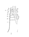
- FIG. 1 is a cross-sectional view schematically showing a jet engine 1 of the present embodiment.
- the jet engine 1 of the present embodiment includes a casing 2, a fan 3, a low pressure compressor 4, a high pressure compressor 5, a combustor 6, a high pressure turbine 7, and a low pressure turbine 8.
- the turbofan engine includes a shaft 9, a thrust booster 10, a variable exhaust nozzle 11 (nozzle), and a control unit 12 (control means).
- the low-pressure compressor 4 is arranged at the most upstream in the core flow path 2b.
- a moving blade row made up of moving blades fixed to the low-pressure shaft 9 a of the shaft 9 and a stationary blade row made up of stationary blades fixed to the casing 2 are alternately arranged in a plurality of stages.
- the moving blade is rotated with the rotation of the shaft 9, and the air taken into the core flow path 2 b is compressed by the moving blade while rectifying the air by the stationary blade.
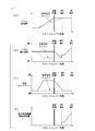
- the jet engine 1 of the present embodiment in the cruising state, has a rotational speed of the fan 3 of 100% in the cruise state, unlike the conventional engine.
- the opening area is large.
- the variable guide vane 3f1 in the cruise state, is in a closed position (an attitude for reducing the inflow angle).
- the variable guide vane 3f1 being closed means that the area of the variable guide vane 3f1 as viewed from the direction of the rotation axis of the fan 3 is apparently wide.
- the intake flow rate of the engine is maintained high, the increase in intake spillage resistance is prevented, and fuel consumption is improved. It can be seen that is improved.
- the opening area of the nozzle 11a is changed in a cruise state where the thrust booster 10 is not used.
- the thrust booster 10 is not used.
- variable guide vane 3fb1 of the variable guide vane mechanism 3fb arranged upstream of the moving blade 3i1 of the fourth stage moving blade row 3i in the fan 32 is the same as the above-described variable guide vane 3f1.
- the variable guide vane 3fb1 is arranged downstream of the third stage stationary blade row 3h with the intermediate flow path 2d interposed therebetween. Also in this case, if the position of the variable guide vane 3fb1 is defined in relation to the intermediate flow path 2d, the variable guide vane 3fb1 is a moving blade (fourth-stage moving blade row 3i located downstream of the intermediate flow path 2d.
- variable guide vane 3fc1 of the variable guide vane mechanism 3fc arranged upstream of the moving blade 3k1 of the fifth stage moving blade row 3k in the fan 33 is the same as the above-described variable guide vane 3f1. You may have the same structure and function. At this time, the variable guide vane 3fc1 is disposed downstream of the fourth stage stationary blade row 3j with the intermediate flow path 2d interposed therebetween.
- variable guide vane 3fc1 is a moving blade (fifth-stage moving blade row 3k) positioned downstream of the intermediate flow path 2d. It can be said that it is located adjacent to the upstream of the rotor blade 3k1).
- the moving blades of the fan 33 fixed to the low pressure shaft 9ac are the moving blade 3b1, the moving blade 3d1, the moving blade 3g1, the moving blade 3i1, and the moving blade 3k1. It is also possible to employ a configuration in which a variable guide vane mechanism is installed for each of the plurality of blade rows.
Landscapes
- Engineering & Computer Science (AREA)
- Chemical & Material Sciences (AREA)
- Combustion & Propulsion (AREA)
- Mechanical Engineering (AREA)
- General Engineering & Computer Science (AREA)
- Physics & Mathematics (AREA)
- Fluid Mechanics (AREA)
- Geometry (AREA)
- Structures Of Non-Positive Displacement Pumps (AREA)
Abstract
L'invention concerne un moteur à réaction (1) qui est pourvu : d'un ventilateur (3, 31, 32, 33) comprenant des pales mobiles (3b1, 3d1, 3g1, 3i1, 3k1) agencées dans une pluralité d'étages ; des compresseurs (4, 5) qui compriment l'air fourni à partir du ventilateur (3, 31, 32, 33) ; un dispositif combustor (6) qui génère des gaz de combustion à l'aide de l'air comprimé généré par les compresseurs (4, 5) ; des turbines (7, 8) qui génèrent une puissance de rotation à partir des gaz de combustion ; et une buse (11a) qui éjecte les gaz de combustion. Ce moteur à réaction (1) est en outre pourvu : d'aubes directrices variables (3f1, 3fa1, 3fb1, 3fc1) qui sont disposées en amont des pales mobiles (3d1, 3g1, 3i1, 3k1) dans le deuxième étage et les étages suivants dans le ventilateur (3, 31, 32, 33), et qui règlent un angle d'entrée d'écoulement de l'écoulement d'air vers les pales mobiles (3d1, 3g1, 3i1, 3k1) dans le deuxième étage et les étages suivants ; un moyen de réglage de résistance au fluide (11b) destiné à régler la résistance au fluide de la buse (11a) ; et un moyen de commande (12) destiné à commander les aubes directrices variables (3f1, 3fa1, 3fb1, 3fc1) de telle sorte que l'angle d'entrée d'écoulement est plus petit en croisière que pendant l'accélération, et à commander le moyen de réglage de la résistance au fluide (11b) de manière à supprimer une augmentation dans la résistance au fluide provenant d'une augmentation dans le débit volumétrique à la sortie du ventilateur (3, 31, 32, 33) associée à la réduction de l'angle d'entrée d'écoulement.
Priority Applications (3)
| Application Number | Priority Date | Filing Date | Title |
|---|---|---|---|
| EP15893346.5A EP3249205B1 (fr) | 2015-05-27 | 2015-05-27 | Moteur à réaction |
| PCT/JP2015/065308 WO2016189712A1 (fr) | 2015-05-27 | 2015-05-27 | Moteur à réaction |
| US15/697,969 US10975775B2 (en) | 2015-05-27 | 2017-09-07 | Jet engine |
Applications Claiming Priority (1)
| Application Number | Priority Date | Filing Date | Title |
|---|---|---|---|
| PCT/JP2015/065308 WO2016189712A1 (fr) | 2015-05-27 | 2015-05-27 | Moteur à réaction |
Related Child Applications (1)
| Application Number | Title | Priority Date | Filing Date |
|---|---|---|---|
| US15/697,969 Continuation US10975775B2 (en) | 2015-05-27 | 2017-09-07 | Jet engine |
Publications (1)
| Publication Number | Publication Date |
|---|---|
| WO2016189712A1 true WO2016189712A1 (fr) | 2016-12-01 |
Family
ID=57392637
Family Applications (1)
| Application Number | Title | Priority Date | Filing Date |
|---|---|---|---|
| PCT/JP2015/065308 Ceased WO2016189712A1 (fr) | 2015-05-27 | 2015-05-27 | Moteur à réaction |
Country Status (3)
| Country | Link |
|---|---|
| US (1) | US10975775B2 (fr) |
| EP (1) | EP3249205B1 (fr) |
| WO (1) | WO2016189712A1 (fr) |
Cited By (1)
| Publication number | Priority date | Publication date | Assignee | Title |
|---|---|---|---|---|
| GB2566354A (en) * | 2017-07-06 | 2019-03-13 | Safran Aircraft Engines | Low fan noise turbojet |
Families Citing this family (4)
| Publication number | Priority date | Publication date | Assignee | Title |
|---|---|---|---|---|
| US20190107046A1 (en) * | 2017-10-05 | 2019-04-11 | General Electric Company | Turbine engine with struts |
| US11814969B2 (en) * | 2021-07-21 | 2023-11-14 | Pratt & Whitney Canada Corp. | Gas turbine engine with low-pressure compressor bypass |
| CN114992670B (zh) * | 2022-05-12 | 2023-06-13 | 中国航发四川燃气涡轮研究院 | 具有可变掺混功能的加力一体化支板 |
| CN116085142B (zh) * | 2023-04-11 | 2023-05-30 | 北京航空航天大学 | 一种级间燃烧变循环发动机的新型总体结构 |
Citations (4)
| Publication number | Priority date | Publication date | Assignee | Title |
|---|---|---|---|---|
| JPS5427613A (en) * | 1977-08-02 | 1979-03-01 | Gen Electric | Method of adjusting byypath current of gas turboofan engine and its device |
| US4221114A (en) * | 1967-01-18 | 1980-09-09 | Rolls-Royce Limited | Gas turbine jet propulsion engine |
| JPH02115558A (ja) * | 1988-09-20 | 1990-04-27 | United Technol Corp <Utc> | 航空機用エンジンの出力制御装置 |
| JP2013506081A (ja) * | 2009-09-25 | 2013-02-21 | ゼネラル・エレクトリック・カンパニイ | コンバーチブルファンエンジン |
Family Cites Families (28)
| Publication number | Priority date | Publication date | Assignee | Title |
|---|---|---|---|---|
| GB875496A (en) | 1959-12-07 | 1961-08-23 | Gen Electric | Improvements in or relating to ducted-fan gas turbine jet propulsion engines |
| CA1020365A (en) | 1974-02-25 | 1977-11-08 | James E. Johnson | Modulating bypass variable cycle turbofan engine |
| US4069661A (en) | 1975-06-02 | 1978-01-24 | The United States Of America As Represented By The United States National Aeronautics And Space Administration | Variable mixer propulsion cycle |
| US4581889A (en) | 1984-10-01 | 1986-04-15 | General Electric Company | Gas turbine engine control |
| US4874289A (en) | 1988-05-26 | 1989-10-17 | United States Of America As Represented By The Secretary Of The Air Force | Variable stator vane assembly for a rotary turbine engine |
| US4947643A (en) | 1988-09-20 | 1990-08-14 | United Technologies Corporation | Active geometry control system for gas turbine engines |
| US5259188A (en) * | 1992-08-24 | 1993-11-09 | General Electric Company | Method and system to increase stall margin |
| US5402638A (en) * | 1993-10-04 | 1995-04-04 | General Electric Company | Spillage drag reducing flade engine |
| US5623823A (en) | 1995-12-06 | 1997-04-29 | United Technologies Corporation | Variable cycle engine with enhanced stability |
| US5809772A (en) * | 1996-03-29 | 1998-09-22 | General Electric Company | Turbofan engine with a core driven supercharged bypass duct |
| US5833140A (en) | 1996-12-12 | 1998-11-10 | United Technologies Corporation | Variable geometry exhaust nozzle for a turbine engine |
| US5911679A (en) * | 1996-12-31 | 1999-06-15 | General Electric Company | Variable pitch rotor assembly for a gas turbine engine inlet |
| US5988980A (en) * | 1997-09-08 | 1999-11-23 | General Electric Company | Blade assembly with splitter shroud |
| JP2000328902A (ja) | 1999-05-19 | 2000-11-28 | Ishikawajima Harima Heavy Ind Co Ltd | ガスタービンエンジン |
| US6487847B1 (en) | 2000-11-03 | 2002-12-03 | General Electric Company | Gas turbine engine fuel control system |
| US7216475B2 (en) | 2003-11-21 | 2007-05-15 | General Electric Company | Aft FLADE engine |
| US7134271B2 (en) | 2004-11-05 | 2006-11-14 | General Electric Company | Thrust vectoring aft FLADE engine |
| US7614210B2 (en) | 2006-02-13 | 2009-11-10 | General Electric Company | Double bypass turbofan |
| US7765789B2 (en) * | 2006-12-15 | 2010-08-03 | General Electric Company | Apparatus and method for assembling gas turbine engines |
| US8127532B2 (en) * | 2008-11-26 | 2012-03-06 | The Boeing Company | Pivoting fan nozzle nacelle |
| US20110167792A1 (en) | 2009-09-25 | 2011-07-14 | James Edward Johnson | Adaptive engine |
| US20110120083A1 (en) * | 2009-11-20 | 2011-05-26 | Rollin George Giffin | Gas turbine engine with outer fans |
| US20120045318A1 (en) | 2010-08-19 | 2012-02-23 | General Electric Company | Method and apparatus for air flow control |
| JP5644302B2 (ja) | 2010-09-15 | 2014-12-24 | 株式会社Ihi | 軸流圧縮機及びガスタービンエンジン |
| US9920710B2 (en) * | 2013-05-07 | 2018-03-20 | General Electric Company | Multi-nozzle flow diverter for jet engine |
| JP6340918B2 (ja) * | 2014-05-23 | 2018-06-13 | 株式会社Ihi | 推力増強装置 |
| US9784285B2 (en) * | 2014-09-12 | 2017-10-10 | Honeywell International Inc. | Variable stator vane assemblies and variable stator vanes thereof having a locally swept leading edge and methods for minimizing endwall leakage therewith |
| FR3048018B1 (fr) * | 2016-02-22 | 2018-03-02 | Safran Aircraft Engines | Dispositif d'application de materiau abradable sur une surface d'un carter de turbomachine |
-
2015
- 2015-05-27 EP EP15893346.5A patent/EP3249205B1/fr active Active
- 2015-05-27 WO PCT/JP2015/065308 patent/WO2016189712A1/fr not_active Ceased
-
2017
- 2017-09-07 US US15/697,969 patent/US10975775B2/en active Active
Patent Citations (4)
| Publication number | Priority date | Publication date | Assignee | Title |
|---|---|---|---|---|
| US4221114A (en) * | 1967-01-18 | 1980-09-09 | Rolls-Royce Limited | Gas turbine jet propulsion engine |
| JPS5427613A (en) * | 1977-08-02 | 1979-03-01 | Gen Electric | Method of adjusting byypath current of gas turboofan engine and its device |
| JPH02115558A (ja) * | 1988-09-20 | 1990-04-27 | United Technol Corp <Utc> | 航空機用エンジンの出力制御装置 |
| JP2013506081A (ja) * | 2009-09-25 | 2013-02-21 | ゼネラル・エレクトリック・カンパニイ | コンバーチブルファンエンジン |
Cited By (2)
| Publication number | Priority date | Publication date | Assignee | Title |
|---|---|---|---|---|
| GB2566354A (en) * | 2017-07-06 | 2019-03-13 | Safran Aircraft Engines | Low fan noise turbojet |
| GB2566354B (en) * | 2017-07-06 | 2022-06-29 | Safran Aircraft Engines | Low fan noise turbojet |
Also Published As
| Publication number | Publication date |
|---|---|
| EP3249205A1 (fr) | 2017-11-29 |
| EP3249205B1 (fr) | 2020-01-29 |
| US20170370295A1 (en) | 2017-12-28 |
| EP3249205A4 (fr) | 2018-09-26 |
| US10975775B2 (en) | 2021-04-13 |
Similar Documents
| Publication | Publication Date | Title |
|---|---|---|
| RU2435057C2 (ru) | Турбовентиляторный газотурбинный двигатель с регулируемыми вентиляторными выходными направляющими лопатками (варианты) | |
| CN108930557B (zh) | 用于压缩机导叶前缘辅助导叶的方法及系统 | |
| JP5121440B2 (ja) | コンバーチブルガスタービンエンジン | |
| US5911679A (en) | Variable pitch rotor assembly for a gas turbine engine inlet | |
| KR101996685B1 (ko) | 레이디얼 유동 터빈, 특히 보조 파워 공급원의 터빈용 가변-피치 노즐 | |
| CN108952823B (zh) | 用于前缘辅助叶片的方法和系统 | |
| US10113486B2 (en) | Method and system for modulated turbine cooling | |
| CN105221295B (zh) | 一种冲压—涡轮喷气复合航空发动机 | |
| US20030033813A1 (en) | Cycle gas turbine engine | |
| JP2016211571A (ja) | 可変ピッチ出口ガイドベーンを有するタービンエンジン | |
| US10760426B2 (en) | Turbine engine with variable effective throat | |
| JP2017535707A (ja) | 航空機タービンエンジンのステータ | |
| EP3260684B1 (fr) | Moteur à turbine à gaz comprenant une boîte de vitesses entre une turbine et un compresseur d'un système de prélèvement d'air | |
| US9989011B2 (en) | Reverse flow single spool core gas turbine engine | |
| WO2016189712A1 (fr) | Moteur à réaction | |
| US20170298742A1 (en) | Turbine engine airfoil bleed pumping | |
| CN104040117A (zh) | 具有齿轮传动架构的燃气涡轮发动机 | |
| US11286856B2 (en) | Diversion of fan air to provide cooling air for gas turbine engine | |
| CN108412636A (zh) | 用于航空动力领域的涡扇发动机核心机 | |
| JP6264161B2 (ja) | ジェットエンジン | |
| US9650962B2 (en) | Rotor noise suppression | |
| JP2010185363A (ja) | ターボファンエンジン | |
| JP7443087B2 (ja) | 軸流圧縮機 | |
| CN116457560B (zh) | 具有改善的推进效率的航空推进系统 | |
| CN104718361B (zh) | 涡轮增压机、涡轮喷嘴及船舶 |
Legal Events
| Date | Code | Title | Description |
|---|---|---|---|
| 121 | Ep: the epo has been informed by wipo that ep was designated in this application |
Ref document number: 15893346 Country of ref document: EP Kind code of ref document: A1 |
|
| REEP | Request for entry into the european phase |
Ref document number: 2015893346 Country of ref document: EP |
|
| NENP | Non-entry into the national phase |
Ref country code: DE |
|
| NENP | Non-entry into the national phase |
Ref country code: JP |