WO2016189902A1 - はんだ付け装置及びフラックス塗布装置 - Google Patents
はんだ付け装置及びフラックス塗布装置 Download PDFInfo
- Publication number
- WO2016189902A1 WO2016189902A1 PCT/JP2016/054595 JP2016054595W WO2016189902A1 WO 2016189902 A1 WO2016189902 A1 WO 2016189902A1 JP 2016054595 W JP2016054595 W JP 2016054595W WO 2016189902 A1 WO2016189902 A1 WO 2016189902A1
- Authority
- WO
- WIPO (PCT)
- Prior art keywords
- nut
- screw shaft
- substrate
- flux
- fixing position
- Prior art date
- Legal status (The legal status is an assumption and is not a legal conclusion. Google has not performed a legal analysis and makes no representation as to the accuracy of the status listed.)
- Ceased
Links
Images


Classifications
-
- B—PERFORMING OPERATIONS; TRANSPORTING
- B23—MACHINE TOOLS; METAL-WORKING NOT OTHERWISE PROVIDED FOR
- B23K—SOLDERING OR UNSOLDERING; WELDING; CLADDING OR PLATING BY SOLDERING OR WELDING; CUTTING BY APPLYING HEAT LOCALLY, e.g. FLAME CUTTING; WORKING BY LASER BEAM
- B23K37/00—Auxiliary devices or processes, not specially adapted for a procedure covered by only one of the other main groups of this subclass
- B23K37/04—Auxiliary devices or processes, not specially adapted for a procedure covered by only one of the other main groups of this subclass for holding or positioning work
- B23K37/0408—Auxiliary devices or processes, not specially adapted for a procedure covered by only one of the other main groups of this subclass for holding or positioning work for planar work
-
- B—PERFORMING OPERATIONS; TRANSPORTING
- B23—MACHINE TOOLS; METAL-WORKING NOT OTHERWISE PROVIDED FOR
- B23K—SOLDERING OR UNSOLDERING; WELDING; CLADDING OR PLATING BY SOLDERING OR WELDING; CUTTING BY APPLYING HEAT LOCALLY, e.g. FLAME CUTTING; WORKING BY LASER BEAM
- B23K1/00—Soldering, e.g. brazing, or unsoldering
- B23K1/0008—Soldering, e.g. brazing, or unsoldering specially adapted for particular articles or work
-
- B—PERFORMING OPERATIONS; TRANSPORTING
- B23—MACHINE TOOLS; METAL-WORKING NOT OTHERWISE PROVIDED FOR
- B23K—SOLDERING OR UNSOLDERING; WELDING; CLADDING OR PLATING BY SOLDERING OR WELDING; CUTTING BY APPLYING HEAT LOCALLY, e.g. FLAME CUTTING; WORKING BY LASER BEAM
- B23K1/00—Soldering, e.g. brazing, or unsoldering
-
- B—PERFORMING OPERATIONS; TRANSPORTING
- B23—MACHINE TOOLS; METAL-WORKING NOT OTHERWISE PROVIDED FOR
- B23K—SOLDERING OR UNSOLDERING; WELDING; CLADDING OR PLATING BY SOLDERING OR WELDING; CUTTING BY APPLYING HEAT LOCALLY, e.g. FLAME CUTTING; WORKING BY LASER BEAM
- B23K1/00—Soldering, e.g. brazing, or unsoldering
- B23K1/0008—Soldering, e.g. brazing, or unsoldering specially adapted for particular articles or work
- B23K1/0016—Soldering of electronic components
-
- B—PERFORMING OPERATIONS; TRANSPORTING
- B23—MACHINE TOOLS; METAL-WORKING NOT OTHERWISE PROVIDED FOR
- B23K—SOLDERING OR UNSOLDERING; WELDING; CLADDING OR PLATING BY SOLDERING OR WELDING; CUTTING BY APPLYING HEAT LOCALLY, e.g. FLAME CUTTING; WORKING BY LASER BEAM
- B23K1/00—Soldering, e.g. brazing, or unsoldering
- B23K1/008—Soldering within a furnace
-
- B—PERFORMING OPERATIONS; TRANSPORTING
- B23—MACHINE TOOLS; METAL-WORKING NOT OTHERWISE PROVIDED FOR
- B23K—SOLDERING OR UNSOLDERING; WELDING; CLADDING OR PLATING BY SOLDERING OR WELDING; CUTTING BY APPLYING HEAT LOCALLY, e.g. FLAME CUTTING; WORKING BY LASER BEAM
- B23K1/00—Soldering, e.g. brazing, or unsoldering
- B23K1/20—Preliminary treatment of work or areas to be soldered, e.g. in respect of a galvanic coating
- B23K1/203—Fluxing, i.e. applying flux onto surfaces
-
- B—PERFORMING OPERATIONS; TRANSPORTING
- B23—MACHINE TOOLS; METAL-WORKING NOT OTHERWISE PROVIDED FOR
- B23K—SOLDERING OR UNSOLDERING; WELDING; CLADDING OR PLATING BY SOLDERING OR WELDING; CUTTING BY APPLYING HEAT LOCALLY, e.g. FLAME CUTTING; WORKING BY LASER BEAM
- B23K3/00—Tools, devices or special appurtenances for soldering, e.g. brazing, or unsoldering, not specially adapted for particular methods
-
- B—PERFORMING OPERATIONS; TRANSPORTING
- B23—MACHINE TOOLS; METAL-WORKING NOT OTHERWISE PROVIDED FOR
- B23K—SOLDERING OR UNSOLDERING; WELDING; CLADDING OR PLATING BY SOLDERING OR WELDING; CUTTING BY APPLYING HEAT LOCALLY, e.g. FLAME CUTTING; WORKING BY LASER BEAM
- B23K3/00—Tools, devices or special appurtenances for soldering, e.g. brazing, or unsoldering, not specially adapted for particular methods
- B23K3/08—Auxiliary devices therefor
-
- B—PERFORMING OPERATIONS; TRANSPORTING
- B23—MACHINE TOOLS; METAL-WORKING NOT OTHERWISE PROVIDED FOR
- B23K—SOLDERING OR UNSOLDERING; WELDING; CLADDING OR PLATING BY SOLDERING OR WELDING; CUTTING BY APPLYING HEAT LOCALLY, e.g. FLAME CUTTING; WORKING BY LASER BEAM
- B23K3/00—Tools, devices or special appurtenances for soldering, e.g. brazing, or unsoldering, not specially adapted for particular methods
- B23K3/08—Auxiliary devices therefor
- B23K3/082—Flux dispensers; Apparatus for applying flux
-
- B—PERFORMING OPERATIONS; TRANSPORTING
- B23—MACHINE TOOLS; METAL-WORKING NOT OTHERWISE PROVIDED FOR
- B23K—SOLDERING OR UNSOLDERING; WELDING; CLADDING OR PLATING BY SOLDERING OR WELDING; CUTTING BY APPLYING HEAT LOCALLY, e.g. FLAME CUTTING; WORKING BY LASER BEAM
- B23K3/00—Tools, devices or special appurtenances for soldering, e.g. brazing, or unsoldering, not specially adapted for particular methods
- B23K3/08—Auxiliary devices therefor
- B23K3/087—Soldering or brazing jigs, fixtures or clamping means
-
- H—ELECTRICITY
- H05—ELECTRIC TECHNIQUES NOT OTHERWISE PROVIDED FOR
- H05K—PRINTED CIRCUITS; CASINGS OR CONSTRUCTIONAL DETAILS OF ELECTRIC APPARATUS; MANUFACTURE OF ASSEMBLAGES OF ELECTRICAL COMPONENTS
- H05K3/00—Apparatus or processes for manufacturing printed circuits
- H05K3/30—Assembling printed circuits with electric components, e.g. with resistors
- H05K3/32—Assembling printed circuits with electric components, e.g. with resistors electrically connecting electric components or wires to printed circuits
- H05K3/34—Assembling printed circuits with electric components, e.g. with resistors electrically connecting electric components or wires to printed circuits by soldering
-
- B—PERFORMING OPERATIONS; TRANSPORTING
- B23—MACHINE TOOLS; METAL-WORKING NOT OTHERWISE PROVIDED FOR
- B23K—SOLDERING OR UNSOLDERING; WELDING; CLADDING OR PLATING BY SOLDERING OR WELDING; CUTTING BY APPLYING HEAT LOCALLY, e.g. FLAME CUTTING; WORKING BY LASER BEAM
- B23K2101/00—Articles made by soldering, welding or cutting
- B23K2101/36—Electric or electronic devices
- B23K2101/42—Printed circuits
Definitions
- the present invention relates to a soldering apparatus using a nut and a flux applying apparatus that can be applied to a soldering apparatus, a flux applying apparatus for applying a flux, and the like for mounting electronic components on a printed wiring board.
- a flux application apparatus is a soldering device using a nut that does not interfere with the rotation of the screw shaft even if part of the flux vaporized by soldering treatment or flux application or the flux adheres and adheres to the screw shaft, etc.
- a soldering device that solders electronic components onto a printed wiring board and a flux application device that applies flux onto the printed wiring board include rails for board conveyance that can be adjusted to the width of the printed wiring board. (For example, refer to Patent Documents 1 and 2). There is also known a support member that supports the printed wiring board to be conveyed from below so that it does not bend under its own weight, and can change the fixing position with respect to the screw shaft in accordance with the size of the printed wiring board.
- solder paste includes powder solder and flux.
- the flux is obtained by dissolving solid components such as rosin, thixotropic agent and activator with a solvent.
- the flux is vaporized and filled in the reflow apparatus by the heating process described above. More specifically, in the preheating zone, particularly the solvent in the flux component is vaporized to form a flux fume. Further, in the flux component, solid components such as rosin are vaporized and become fumes when they are exposed to a high temperature in this heating zone, and float inside the apparatus.
- a part of the vaporized flux fumes adjusts the fixing position to support a member (screw shaft, nut, etc.) or a substrate that makes the rail for transporting the printed wiring board a rail width corresponding to the board size. If it adheres to the surface of a possible member (screw shaft, nut, etc.), it will become fluid flux fumes with a drop in temperature. The liquefied flux fume eventually solidifies. The solidified flux fume is hard to peel off and adheres hard, so it cannot be easily peeled off by rotation of the screw shaft. This makes it difficult to advance the nut, and makes it difficult to adjust the fixing position with respect to the screw shaft.
- the dropped flux adheres to and adheres to the screw shaft, and the fixed flux cannot be easily peeled off by rotating the screw shaft. Therefore, there is a similar problem that the fixing position of the nut with respect to the screw shaft cannot be changed by moving forward and backward.
- JP 2001-44619 A Japanese Patent Laid-Open No. 06-53644 JP 11-62938 A JP 2001-27215 A Japanese Utility Model Publication No. 62-80009
- Patent Documents 1 and 2 have not taken any measures against the above problem.
- the screws or nuts disclosed in the above Patent Documents 3 to 5 are only intended to move in one direction in order to loosen the screws when a coating film or the like is fixed, and are only relative to the screw shaft. No assumption is made about the provision of a device for performing an operation of changing the nut fixing position by advancing and retracting, and no countermeasure has been taken against the above problem.
- the present invention solves such a problem, and is solidified by adhering to a member (screw shaft or nut) that changes the fixing position corresponding to the board size in the soldering device or the flux coating device.
- the purpose is to remove flux fume.
- Another object of the present invention is to remove the adhering matter adhered to the screw shaft and the nut when the adhering matter adheres to the screw shaft.
- the technical means of the present invention taken in order to solve the above-mentioned problems are as follows.
- the fixing position with respect to the screw shaft can be advanced and retracted, and the nut having the connecting flange portion is supported, and the substrate is supported to prevent the warpage of the substrate and is fixed to the nut via the connecting flange portion.
- the nut includes a screw portion from the front end to the rear end of the nut, and has one or more non-engaging portions that do not mesh with the screw shaft over the entire length of the nut, and supports the substrate by rotating the screw shaft.
- a soldering apparatus in which, when the fixing position of the part is changed, the adhered matter attached to the screw shaft is scraped off by the end face of the non-meshing portion as the screw shaft rotates.
- the non-meshing portion has a discharge port at the front end and the rear end of the nut, and discharges more scraped deposits from the discharge port on the side where the deposits are scraped off.
- An adjustment member of the flux coating apparatus that is changed in accordance with the width of the substrate to be transported, the adjustment member being a screw shaft that is driven to rotate, and a screw shaft that is driven by rotation of the screw shaft.
- the nut can be moved forward and backward with respect to the nut and has a flange portion for connection, and the width of the substrate transport rail can be changed corresponding to the width of the substrate and can be fixed to the nut via the flange portion for connection.
- the nut has a screw part from the front end to the rear end, and has one or more non-engagement parts that do not mesh with the screw shaft over the entire length of the nut, and rotates the screw shaft
- the flux applying apparatus in which the adhering matter attached to the screw shaft is scraped off by the end face of the non-meshing portion as the screw shaft rotates.
- the non-meshing portion has a discharge port at the front and rear ends of the nut, and discharges more scraped deposits from the discharge port on the side where the deposits are scraped off.
- the deposit can be peeled off by the action of the non-meshing portion.
- the deposits removed with the nut are peeled off or scraped off to the non-meshing part without being fixed to the other screw shaft (screw valley) again.
- the rotation of the shaft is not hindered, and the rotation of the screw shaft becomes smooth.
- the nut fixing position can be changed (adjusted) more easily than in the prior art.
- the flux fume that is attached and solidified on a member that changes the fixing position corresponding to the width of the substrate in each apparatus. Since it is removed while shaving, the nut can be easily moved back and forth with respect to the screw shaft, and the fixing position of the nut can be easily changed. Accordingly, the flux adhering to the screw shaft can be easily removed, and the fixing position of the substrate transport rail or the substrate support member can be easily adjusted in accordance with the substrate size. Since the adhered flux can be easily removed, the time and cost required for the maintenance of the apparatus can be reduced.
- soldering device and the flux application device are configured to be able to change the nut fixing position by rotating the screw shaft, when changing the nut fixing position, the upper and lower positions of the non-engagement portion Since there is no change, the peeled-off fixed object can be discharged out of the nut without being involved in the rotation of the screw shaft and preventing the nut from moving forward and backward.
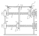
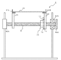
- FIG. 1 is a schematic plan view showing a configuration example of a soldering apparatus 1 as a first embodiment according to the present invention.
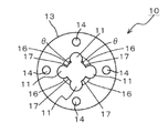
- 3 is a plan view showing a configuration example of a nut 10.
- FIG. 2 is a perspective view showing a configuration example of a nut 10.
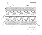
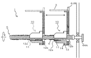
- FIG. 3 is a cross-sectional view taken along line AA in FIG. 2B showing a configuration example of the nut 10. It is a partial cross section figure which shows the example of adjustment when the nut 10 is attached to the soldering apparatus 1.
- FIG. It is an expanded sectional view which shows the example of adjustment when the nut 10 is attached to the soldering apparatus 1.
- FIG. It is a schematic plan view which shows the structural example of the flux application
- the soldering apparatus 1 is an apparatus that heats and solders, for example, a printed wiring board 3 or the like in which a solder paste is applied to predetermined electrodes.
- the soldering apparatus 1 corresponds to the transport rails 61L and 61R, the board support portion 66 that supports the printed wiring board 3 from the vertically downward direction corresponding to the width of the printed wiring board 3, and the width of the printed wiring board 3.
- the adjustment member is changed.
- the adjustment member there are provided screw shafts 5 and 50 and a nut 10 which can change the fixing position with respect to the screw shafts 5 and 50, respectively.
- the transport rail 61L is set as a fixed rail
- the transport rail 61R is set as a movable rail.
- the soldering apparatus 1 includes the following members.
- the transport rail 61R is supported by a rail support portion 62.
- the rail support portion 62 is connected to the connection hole 14 of the nut 10 by a screw or the like.
- the nut 10 is screwed onto the screw shaft 5.
- Both ends of the screw shaft 5 are rotatably supported by a pair of bearing portions 63A, and are rotated by a rotating member 64A. As the screw shaft 5 rotates in the forward / reverse direction, the nut 10 engaged therewith advances and retreats along the screw shaft 5.
- the transport rail 61R advances and retreats along the screw shaft 5.
- the rail 61L for conveyance is supported by the rail support part 65, since this rail support part 65 is comprised so that it may not mesh with the screw shaft 5 (not shown), even if the screw shaft 5 rotates.
- the transport rail 61L does not move and is fixed at that position.
- the rotating member 64A when the rotating member 64A is rotated, the nut 10 moves forward and backward, the screwing position of the screw shaft 5 and the nut 10 changes, and the fixing position of the nut 10 with respect to the screw shaft 5 can be changed.
- the width between the pair of transport rails 61L and 61R can be changed in accordance with the width of the printed wiring board 3.
- the soldering apparatus 1 is provided with a board support portion 66.
- the soldering apparatus 1 includes the following members as adjustment members that change the fixing position of the substrate support portion 66 with respect to the screw shaft 50.
- the substrate support part 66 is supported by a support part 67.
- the support portion 67 is connected to the connection hole 14 of the nut 10 by a screw or the like.
- the nut 10 is screwed onto the screw shaft 50.
- Both ends of the screw shaft 50 are rotatably supported by the pair of bearing portions 63B, and are rotated by the rotating member 64B.
- the screw shaft 50 rotates in the forward / reverse direction
- the nut 10 meshing with the screw shaft 50 advances and retreats along the screw shaft 50.
- the substrate support portion 66 advances and retracts along the screw shaft 50.
- the nut 10 shown in FIGS. 2A and 2B can be screwed onto the screw shafts 5 and 50 (see FIG. 1) having a predetermined length, and the fixing position of the nut 10 can be changed with respect to the screw shafts 5 and 50. It can be done.
- the thread valley 16 of the nut 10 is indicated by a thin line arc.
- the thread 17 of the nut 10 is indicated by a thick arc.
- the nut 10 shown in FIG. 2B does not mesh with the screw shafts 5 and 50, and has four non-meshing portions 11 in this example.
- One end portion of the nut 10 has a flange portion 13 for connection to another member.
- the non-meshing portion 11 is formed by cutting out the thread of the nut 10 in an arc shape outward.
- the flange portion 13 includes four connection holes 14 so that the flange portion 13 can be connected to other members with screws or the like.
- non-meshing portions 11 In the case where four non-meshing portions 11 are provided as in this example, it is preferable to form so as to maintain an angular interval of approximately 90 degrees.
- the four non-meshing portions 11 can efficiently peel off the deposits to be described later even when the deposits are harder.
- the shape of the non-meshing portion 11 is not limited to an arc shape. Although the diameter (width) of the non-engagement part 11 is not ask
- FIG. The angle ⁇ (see FIG. 2A) formed by the screw thread 17 and the non-engagement portion 11 is not limited, but is preferably 90 degrees or less, and even when the deposits described later are more firmly attached to the non-engagement portion 11. It can be peeled off efficiently.
- the non-meshing portion 11 has a total length (overall from the front end to the rear end of the nut 10 in parallel with the traveling direction with respect to the screw shafts 5 and 50 (not shown in this figure) of the nut 10. ).
- the opening on one end side of the nut 10 forms the first discharge port 12a, and the opening on the other end side forms the second discharge port 12b.
- the nut 10 is provided with four non-meshing portions 11, but the present invention is not limited to this, and it is sufficient that one or more non-meshing portions 11 are provided.
- the pair of non-meshing parts 11 are preferably provided symmetrically in the radial direction of the nut 10.
- the nut 10 is made of metal such as brass, but stainless steel may be used. In the case of using stainless steel, it is more preferable that the surface is nitrided by a known means after processing because the surface becomes hard and smooth. The same applies to the nut material.
- the nut 10 and the screw shafts 5 and 50 are trapezoidal screws in this embodiment, but are not limited thereto, and may be ball screws or triangular screws, for example.
- the non-engagement portion 11 is formed on the nut 10 by an end mill or the like. After making a hole in the nut 10, the burr is removed. The non-meshing portion 11 is formed so as to cut out the thread of the nut 10. The non-meshing portion 11 is formed over the entire length (entire) from the front end to the rear end of the nut 10 in parallel with the traveling direction with respect to the screw shafts 5 and 50.
- FIGS. 1, 4A, and 4B an example of adjusting the fixing position of the nut 10 attached to the soldering apparatus 1 will be described with reference to FIGS. 1, 4A, and 4B.
- the non-engagement part 11 has shown only one place for description.
- the transport rail 61L is a fixed rail whose position in the width direction is fixed, and the transport rail 61R and the substrate support section 66 are movable rails.
- the screw shafts 5 and 50 and the nut 10 change the fixing positions of the transport rail 61R and the substrate support portion 66.
- the nut 10 advances and retreats. For example, when the width of the printed wiring board 3 is large, when the rotating members 64A and 64B are rotated in the clockwise direction when viewed from the right side of the drawing, the transport rail 61R and the board support portion 66 are separated from the transport rail 61L (see FIG. The nut 10 moves to the right side in the middle.
- This shaving residue is mainly scraped off from the traveling direction side of the nut 10.
- a large amount of shavings is discharged from the first discharge port 12a.
- the shavings are accumulated in the non-engagement portion 11 and are also discharged from the second discharge port 12b.
- a large amount of shavings is discharged from the second discharge port 12b.
- the scraps are collected in the non-engagement portion 11 and are also discharged from the first discharge port 12a. As a result, the scraped scraps do not adhere to the nut 10 and the screw shaft 5 again to prevent the nut 10 from moving forward and backward.
- the non-engagement portion 11 acts to scrape and remove the fixed matter 6.
- the fixed object 6 scraped off by the non-meshing portion 11 is accumulated in the non-meshing portion 11 and falls from the first discharge port 12a or the second discharge port 12b.
- the operation of the substrate support portion 66 shown in FIG. 1 is the same as the operation of the transport rail 61R.
- the nut 10 even if the screw shafts 5 and 50 have the fixed object 6 when the soldering apparatus 1 is used for a long period of time, the nut 10 is simply rotated so as to advance on the screw shafts 5 and 50.
- the non-meshing portion 11 acts to scrape and remove the fixed object 6. Therefore, the flux fume that adheres to the screw shafts 5 and 50 and the nut 10 and solidifies can be easily removed, and the fixing position of the nut 10 can be easily changed.
- the fixed object 6 attached to the screw shafts 5 and 50 and the nut 10 can be easily removed, and the fixing position of the transport rail 61R or the board support 66 can be easily adjusted according to the width of the printed wiring board 3 to be transported. Can be adjusted. Since the adhered adhering matter 6 can be easily removed, the time and cost required for the maintenance of the apparatus can be reduced.
- the nut 10 Since the nut 10 has a non-engagement portion 11 and does not rotate, and the screw shafts 5 and 50 rotate, the nut 10 can be fixed to the screw shafts 5 and 50 so that the nut 10 can be fixed. Is changed, the vertical position of the non-meshing portion 11 does not change. For this reason, the peeled fixed object 6 is again caught in the rotation of the screw shafts 5 and 50 and discharged out of the nut 10 without preventing the nut 10 from moving forward and backward.
- the flux coating apparatus 2 includes rails 61L and 61R for conveyance and an adjustment member that is changed according to the width of the printed wiring board 30.
- As the adjusting member a screw shaft 5 having a predetermined length and a nut 10 that can be screwed into the screw shaft 5 to change a fixing position with respect to the screw shaft 5 are provided.
- the transport rail 61L is set as a fixed rail
- the transport rail 61R is set as a movable rail.
- the flux application device 2 includes the following members.
- the transport rail 61R is supported by a rail support portion 62.
- the rail support portion 62 is connected to the connection hole 14 of the flange portion 13 of the nut 10 by a screw or the like.
- the nut 10 is screwed onto the screw shaft 5. Both ends of the screw shaft 5 are rotatably supported by a pair of bearing portions 63A, and are rotated by a rotating member 64A. Due to the rotation of the screw shaft 5, the nut 10 engaged with the screw shaft 5 advances and retreats along the screw shaft 5.
- the transport rail 61R advances and retreats along the screw shaft 5.
- the rail 61L for conveyance is supported by the rail support part 65, since this rail support part 65 is comprised so that it may not mesh with the screw shaft 5 (not shown), even if the screw shaft 5 rotates.
- the transport rail 61L does not move and is fixed at that position.
- the rotating member 64A when the rotating member 64A is rotated, the nut 10 moves forward and backward, the screwing position of the screw shaft 5 and the nut 10 changes, and the fixing position of the nut 10 with respect to the screw shaft 5 can be changed. Thereby, the width between the pair of transfer rails 61L and 61R can be changed in accordance with the size of the printed wiring board 30.
- the nut 10 performs the same operation as the nut 10 of the first embodiment shown in FIGS. 4A and 4B. At this time, even if flux fume or the like is fixed to the screw shaft 5, the non-engagement portion 11 not shown in this figure is fixed only by rotating the rotating member 64 ⁇ / b> A so that the nut 10 advances on the screw shaft 5. Is removed, and the air is discharged from the first discharge port 12a or the second discharge port 12b. Thereby, the flux fume which adhered to the screw shaft 5 and the nut 10 and solidified can be easily removed, and the fixing position of the nut 10 can be easily changed. Therefore, the time and cost required for the maintenance of the flux application device 2 can be reduced.
- the present invention can be applied to the case where the adherent adheres to the screw shaft because the adherent can be peeled off by the action of the non-meshing portion even if the adherent adheres to the screw shaft.
- the present invention is extremely suitable when applied to a soldering apparatus, a flux coating apparatus, a paint coating apparatus, and the like to which a flux fume is fixed.
Landscapes
- Engineering & Computer Science (AREA)
- Mechanical Engineering (AREA)
- Manufacturing & Machinery (AREA)
- Microelectronics & Electronic Packaging (AREA)
- Physics & Mathematics (AREA)
- Optics & Photonics (AREA)
- Electric Connection Of Electric Components To Printed Circuits (AREA)
- Transmission Devices (AREA)
Abstract
Description
(1)搬送される基板の幅に対応して変更されるはんだ付け装置の基板反り防止機構の調整部材であって、調整部材は、回転駆動されるネジ軸と、ネジ軸が回転駆動されることにより、ネジ軸に対する固定位置を進退可能になされるとともに連結用のフランジ部を有するナットと、基板を支持して基板の反りを防止するとともに連結用のフランジ部を介してナットに固定される基板支持部とを備え、ナットはその先端から後端までネジ部を有すると共に、ナットの全長に亘り、ネジ軸に噛合しない1以上の非噛合部を有し、ネジ軸を回転させて基板支持部の固定位置を変更するとき、ネジ軸に付着した付着物が、ネジ軸の回転に伴って非噛合部の端面によって削り取られるはんだ付け装置。
図1~図3を参照して、本発明の第1の実施の形態に係るはんだ付け装置1の構成例を説明する。
図1に示すように、はんだ付け装置1は、例えばはんだペーストが所定の電極に塗布されたプリント配線基板3等を加熱処理してはんだ付けする装置である。はんだ付け装置1は、搬送用レール61L、61Rと、プリント配線基板3の幅に対応してプリント配線基板3を鉛直下方向から支持する基板支持部66と、プリント配線基板3の幅に対応して変更される調整部材を備える。この調整部材として、ネジ軸5、50と、ネジ軸5、50に対してそれぞれ固定位置を変更可能になされるナット10とが備えられる。
ナット10は、真鍮等の金属からなるが、ステンレスを用いても良い。ステンレスを用いる場合は加工後に表面を公知の手段で窒化処理すると、表面が硬く滑らかになるのでより好ましい。以下ナットの素材については同様である。ナット10及びネジ軸5、50は、この実施の形態においては、台形ネジであるが、これに限られず、例えばボールねじ、三角ネジであっても良い。
ナット10に既知の方法でネジ山を設けた後、非噛合部11は、ナット10にエンドミル等で加工形成される。ナット10に穴を開けた後、バリを取り除く。非噛合部11は、ナット10のネジ山を切り欠くように形成される。非噛合部11は、ネジ軸5、50に対する進行方向と平行に、ナット10の先端から後端に至るまでの全長(全体)に亘って形成される。
続いて、図5を参照して、第2の実施の形態としてのフラックス塗布装置2の構成例について説明する。第1の実施の形態で使用したのと同じ部材には同じ符号を付し、その詳細な説明は省略する。
2 フラックス塗布装置
5、50 ネジ軸
10 ナット
11 非噛合部
12a 第1の排出口
12b 第2の排出口
13A フランジ部
14A 連結穴
61L,61R 搬送用レール
62,65 レール支持部
63A,63B 軸受部
64A,64B 回転部材
66 基板支持部
67 支持部
Claims (6)
- 搬送される基板の幅に対応して変更されるはんだ付け装置の基板反り防止機構の調整部材であって、
前記調整部材は、
回転駆動されるネジ軸と、
該ネジ軸が回転駆動されることにより、前記ネジ軸に対する固定位置を進退可能になされるとともに連結用のフランジ部を有するナットと、
前記基板を支持して基板の反りを防止するとともに前記連結用のフランジ部を介して前記ナットに固定される基板支持部とを備え、
前記ナットはその先端から後端までネジ部を有すると共に、前記ナットの全長に亘り前記ネジ軸に噛合しない1以上の非噛合部を有し、
前記ネジ軸を回転させて前記基板支持部の固定位置を変更するとき、
前記ネジ軸に付着した付着物が、前記ネジ軸の回転に伴って前記非噛合部の端面によって削り取られるはんだ付け装置。 - 前記非噛合部は、
前記ナットの前記先端及び前記後端に、排出口を有し、
前記付着物を削りとった側の前記排出口から、より多くの削り取られた前記付着物を排出する請求項1に記載のはんだ付け装置。 - 前記ネジ軸に対する前記ナットの固定位置を変更する際に、
前記非噛合部の上下位置を変えることなく前記付着物を削り取る請求項1に記載のはんだ付け装置。 - 搬送される基板の幅に対応して変更されるフラックス塗布装置の調整部材であって、
前記調整部材は、
回転駆動されるネジ軸と、
該ネジ軸が回転駆動されることにより、前記ネジ軸に対する固定位置を進退可能になされるとともに連結用のフランジ部を有するナットと、
前記基板の幅に対応して基板搬送用レールの幅を変更するとともに前記連結用のフランジ部を介して前記ナットに固定される前記基板搬送用レールの支持部とを備え、
前記ナットはその先端から後端までネジ部を有すると共に、前記ナットの全長に亘り前記ネジ軸に噛合しない1以上の非噛合部を有し、
前記ネジ軸を回転させて前記基板搬送用レールの固定位置を変更するとき、
前記ネジ軸に付着した付着物が、前記ネジ軸の回転に伴って前記非噛合部の端面によって削り取られるフラックス塗布装置。 - 前記非噛合部は、
前記ナットの前記先端及び前記後端に、排出口を有し、
前記付着物を削りとった側の前記排出口から、より多くの削り取られた前記付着物を排出する請求項4に記載のフラックス塗布装置。 - 前記ネジ軸に対する前記ナットの固定位置を変更する際に、
前記非噛合部の上下位置を変えることなく前記付着物を削り取る請求項4に記載のフラックス塗布装置。
Priority Applications (6)
| Application Number | Priority Date | Filing Date | Title |
|---|---|---|---|
| KR1020177036713A KR101855642B1 (ko) | 2015-05-25 | 2016-02-17 | 솔더링 장치 및 플럭스 도포 장치 |
| CN201680030503.0A CN107615897A (zh) | 2015-05-25 | 2016-02-17 | 锡焊装置以及焊剂涂敷装置 |
| EP16799611.5A EP3307034B1 (en) | 2015-05-25 | 2016-02-17 | Soldering device |
| US15/576,293 US10293439B2 (en) | 2015-05-25 | 2016-02-17 | Soldering apparatus and flux-applying device |
| TW105111195A TWI638700B (zh) | 2015-05-25 | 2016-04-11 | Solder addition device and flux coating device |
| PH12017502125A PH12017502125A1 (en) | 2015-05-25 | 2017-11-21 | Soldering apparatus and flux-applying device |
Applications Claiming Priority (2)
| Application Number | Priority Date | Filing Date | Title |
|---|---|---|---|
| JP2015105390 | 2015-05-25 | ||
| JP2015-105390 | 2015-05-25 |
Publications (1)
| Publication Number | Publication Date |
|---|---|
| WO2016189902A1 true WO2016189902A1 (ja) | 2016-12-01 |
Family
ID=57393116
Family Applications (1)
| Application Number | Title | Priority Date | Filing Date |
|---|---|---|---|
| PCT/JP2016/054595 Ceased WO2016189902A1 (ja) | 2015-05-25 | 2016-02-17 | はんだ付け装置及びフラックス塗布装置 |
Country Status (9)
| Country | Link |
|---|---|
| US (1) | US10293439B2 (ja) |
| EP (1) | EP3307034B1 (ja) |
| KR (1) | KR101855642B1 (ja) |
| CN (2) | CN107615897A (ja) |
| HU (1) | HUE068856T2 (ja) |
| MY (1) | MY176685A (ja) |
| PH (1) | PH12017502125A1 (ja) |
| TW (1) | TWI638700B (ja) |
| WO (1) | WO2016189902A1 (ja) |
Cited By (2)
| Publication number | Priority date | Publication date | Assignee | Title |
|---|---|---|---|---|
| CN115155868A (zh) * | 2022-07-11 | 2022-10-11 | 厦门视界至尚新材料有限公司 | 一种板材防水用涂漆设备及其工艺方法 |
| CN116571936A (zh) * | 2023-04-04 | 2023-08-11 | 中通客车股份有限公司 | 一种螺母附件焊接定位装置及方法 |
Families Citing this family (6)
| Publication number | Priority date | Publication date | Assignee | Title |
|---|---|---|---|---|
| JP6508299B1 (ja) * | 2017-11-29 | 2019-05-08 | 千住金属工業株式会社 | 噴流はんだ高さ確認治具及びその取り扱い方法 |
| CN110203712B (zh) * | 2019-04-26 | 2024-11-01 | 湖南中冶长天重工科技有限公司 | 一种焊接型辊臂及其焊接定位工装 |
| CN112469208B (zh) * | 2020-10-23 | 2021-11-23 | 温州瓯斯达电器实业有限公司 | 电热蚊香液加热器的pcb电路板元件对点焊接设备 |
| DE102021129127A1 (de) * | 2021-11-09 | 2023-05-11 | Ersa Gmbh | Transportsystem zum Transportieren von Lötgut durch eine Lötanlage und Lötanlage |
| DE102021129079B3 (de) | 2021-11-09 | 2022-11-24 | Ersa Gmbh | Transportsystem zum Transportieren von Lötgut durch eine Lötanlage und Lötanlage |
| CN114603227B (zh) * | 2022-03-23 | 2023-12-05 | 美的集团股份有限公司 | 波峰焊设备及其控制方法和控制装置 |
Citations (6)
| Publication number | Priority date | Publication date | Assignee | Title |
|---|---|---|---|---|
| JPS55147517U (ja) * | 1979-04-11 | 1980-10-23 | ||
| JPS6327712U (ja) * | 1986-08-06 | 1988-02-23 | ||
| JPH06198428A (ja) * | 1992-12-29 | 1994-07-19 | Nippon Seiki Co Ltd | 発泡式フラックス塗布装置 |
| JP2001065663A (ja) * | 1999-08-27 | 2001-03-16 | Sony Corp | スライダ及びはんだ付け装置 |
| JP2002240920A (ja) * | 2001-02-20 | 2002-08-28 | Tamura Seisakusho Co Ltd | 搬送装置および加熱装置 |
| JP2008291924A (ja) * | 2007-05-24 | 2008-12-04 | Sumitomo Kinzoku Kozan Siporex Kk | パネル取付用ナット及び軽量気泡コンクリートパネルの取付構造 |
Family Cites Families (16)
| Publication number | Priority date | Publication date | Assignee | Title |
|---|---|---|---|---|
| JPS4891379U (ja) | 1972-02-12 | 1973-11-02 | ||
| JPS6173818U (ja) | 1984-10-18 | 1986-05-19 | ||
| JPS61146611U (ja) * | 1985-03-05 | 1986-09-10 | ||
| JPS6280009U (ja) | 1985-11-09 | 1987-05-22 | ||
| JPS6464747A (en) | 1987-09-02 | 1989-03-10 | Mazda Motor | Feeding device for machine tool |
| JP3095291B2 (ja) | 1992-07-16 | 2000-10-03 | 平田機工株式会社 | ハンダ装置 |
| JP3815863B2 (ja) | 1997-08-21 | 2006-08-30 | 株式会社杉浦製作所 | 雌ねじ部材 |
| JP3541132B2 (ja) | 1998-11-11 | 2004-07-07 | Thk株式会社 | ボールねじ |
| JP2000174430A (ja) * | 1998-12-03 | 2000-06-23 | Tdk Corp | リフロー炉における基板反り防止装置 |
| JP3739602B2 (ja) | 1999-07-12 | 2006-01-25 | イワタボルト株式会社 | ボルト |
| JP2001044619A (ja) * | 1999-08-04 | 2001-02-16 | Koyo Thermo System Kk | 連続熱処理炉 |
| TWI289033B (en) * | 2002-11-25 | 2007-10-21 | Senju Metal Industry Co | Solder reflow oven |
| CN202106163U (zh) * | 2011-04-27 | 2012-01-11 | 昆山市苏俊电子有限公司 | 一种焊接工装治具 |
| CN103801792B (zh) * | 2012-11-12 | 2016-08-10 | 台达电子电源(东莞)有限公司 | 喷雾机 |
| CN105764820B (zh) | 2013-10-08 | 2019-01-22 | 雅马哈发动机株式会社 | 基板搬运装置 |
| CN103600163B (zh) * | 2013-11-22 | 2015-08-19 | 沈阳大学 | 窄间隙埋弧焊熔渣清理装置 |
-
2016
- 2016-02-17 MY MYPI2017001687A patent/MY176685A/en unknown
- 2016-02-17 CN CN201680030503.0A patent/CN107615897A/zh active Pending
- 2016-02-17 US US15/576,293 patent/US10293439B2/en active Active
- 2016-02-17 KR KR1020177036713A patent/KR101855642B1/ko active Active
- 2016-02-17 WO PCT/JP2016/054595 patent/WO2016189902A1/ja not_active Ceased
- 2016-02-17 CN CN202110212993.9A patent/CN113000959A/zh active Pending
- 2016-02-17 HU HUE16799611A patent/HUE068856T2/hu unknown
- 2016-02-17 EP EP16799611.5A patent/EP3307034B1/en active Active
- 2016-04-11 TW TW105111195A patent/TWI638700B/zh active
-
2017
- 2017-11-21 PH PH12017502125A patent/PH12017502125A1/en unknown
Patent Citations (6)
| Publication number | Priority date | Publication date | Assignee | Title |
|---|---|---|---|---|
| JPS55147517U (ja) * | 1979-04-11 | 1980-10-23 | ||
| JPS6327712U (ja) * | 1986-08-06 | 1988-02-23 | ||
| JPH06198428A (ja) * | 1992-12-29 | 1994-07-19 | Nippon Seiki Co Ltd | 発泡式フラックス塗布装置 |
| JP2001065663A (ja) * | 1999-08-27 | 2001-03-16 | Sony Corp | スライダ及びはんだ付け装置 |
| JP2002240920A (ja) * | 2001-02-20 | 2002-08-28 | Tamura Seisakusho Co Ltd | 搬送装置および加熱装置 |
| JP2008291924A (ja) * | 2007-05-24 | 2008-12-04 | Sumitomo Kinzoku Kozan Siporex Kk | パネル取付用ナット及び軽量気泡コンクリートパネルの取付構造 |
Non-Patent Citations (1)
| Title |
|---|
| See also references of EP3307034A4 * |
Cited By (2)
| Publication number | Priority date | Publication date | Assignee | Title |
|---|---|---|---|---|
| CN115155868A (zh) * | 2022-07-11 | 2022-10-11 | 厦门视界至尚新材料有限公司 | 一种板材防水用涂漆设备及其工艺方法 |
| CN116571936A (zh) * | 2023-04-04 | 2023-08-11 | 中通客车股份有限公司 | 一种螺母附件焊接定位装置及方法 |
Also Published As
| Publication number | Publication date |
|---|---|
| EP3307034B1 (en) | 2024-08-21 |
| PH12017502125B1 (en) | 2018-05-28 |
| TW201707835A (zh) | 2017-03-01 |
| US10293439B2 (en) | 2019-05-21 |
| HUE068856T2 (hu) | 2025-02-28 |
| PH12017502125A1 (en) | 2018-05-28 |
| EP3307034A1 (en) | 2018-04-11 |
| CN107615897A (zh) | 2018-01-19 |
| KR101855642B1 (ko) | 2018-05-04 |
| MY176685A (en) | 2020-08-19 |
| US20180141168A1 (en) | 2018-05-24 |
| TWI638700B (zh) | 2018-10-21 |
| KR20180003621A (ko) | 2018-01-09 |
| EP3307034A4 (en) | 2019-06-12 |
| CN113000959A (zh) | 2021-06-22 |
Similar Documents
| Publication | Publication Date | Title |
|---|---|---|
| KR101855642B1 (ko) | 솔더링 장치 및 플럭스 도포 장치 | |
| JP5878219B1 (ja) | はんだ付け装置 | |
| JP5928649B1 (ja) | はんだ付け装置及びフラックス塗布装置 | |
| US9796035B2 (en) | Screen printing machine, electronic component mounting system, and screen printing method | |
| WO2008150913A3 (en) | Multiple laser wavelength and pulse width process drilling | |
| JP5928635B2 (ja) | はんだ付け装置 | |
| JP2016080164A5 (ja) | はんだ付け装置 | |
| TWI816663B (zh) | 靶材的洗淨方法與靶材洗淨裝置、靶材的製造方法以及回收鑄塊的製造方法 | |
| Tseng et al. | Superhydrophobic graphene/ceramic templates for the preparation of particulate drugs | |
| KR100659452B1 (ko) | 솔더영역 형성장치, 방법 및 연속 도금장치 | |
| JP2008290021A (ja) | ドラムドライヤの掻取り装置及びそれに用いるスクレーパー | |
| Zhao et al. | Spreading kinetics of liquid solders over an intermetallic solid surface. Part 2: Lead-free solders | |
| CN211335071U (zh) | 一种全自动印刷机 | |
| JP6849909B2 (ja) | はんだ付け方法、はんだ付け装置、及び噴流ノズルのはんだ濡れの保持方法 | |
| JP5208618B2 (ja) | 回路基板の端面被覆装置 | |
| JP4497588B2 (ja) | はんだ付け装置 | |
| KR102181786B1 (ko) | 아연도금설비 | |
| JP2004307895A (ja) | プリント配線基板のスプレー処理装置 | |
| WO2023243576A1 (ja) | 噴流はんだ付け装置 | |
| JP6233561B2 (ja) | フラックス転写用テープ | |
| JP2005236000A (ja) | 自動はんだ付け装置 | |
| DE10144099A1 (de) | Verfahren und Vorrichtung zum Bearbeiten von Leiterplatten | |
| TWM332576U (en) | Recycling apparatus for composite board |
Legal Events
| Date | Code | Title | Description |
|---|---|---|---|
| 121 | Ep: the epo has been informed by wipo that ep was designated in this application |
Ref document number: 16799611 Country of ref document: EP Kind code of ref document: A1 |
|
| WWE | Wipo information: entry into national phase |
Ref document number: 12017502125 Country of ref document: PH |
|
| WWE | Wipo information: entry into national phase |
Ref document number: 15576293 Country of ref document: US |
|
| NENP | Non-entry into the national phase |
Ref country code: DE |
|
| ENP | Entry into the national phase |
Ref document number: 20177036713 Country of ref document: KR Kind code of ref document: A |
|
| WWE | Wipo information: entry into national phase |
Ref document number: 2016799611 Country of ref document: EP |