WO2016189903A1 - 熱延鋼板の冷却装置及びそのマスク部材位置調整方法 - Google Patents
熱延鋼板の冷却装置及びそのマスク部材位置調整方法 Download PDFInfo
- Publication number
- WO2016189903A1 WO2016189903A1 PCT/JP2016/054779 JP2016054779W WO2016189903A1 WO 2016189903 A1 WO2016189903 A1 WO 2016189903A1 JP 2016054779 W JP2016054779 W JP 2016054779W WO 2016189903 A1 WO2016189903 A1 WO 2016189903A1
- Authority
- WO
- WIPO (PCT)
- Prior art keywords
- hot
- rolled steel
- steel sheet
- plate
- width direction
- Prior art date
- Legal status (The legal status is an assumption and is not a legal conclusion. Google has not performed a legal analysis and makes no representation as to the accuracy of the status listed.)
- Ceased
Links
Images



Classifications
-
- B—PERFORMING OPERATIONS; TRANSPORTING
- B21—MECHANICAL METAL-WORKING WITHOUT ESSENTIALLY REMOVING MATERIAL; PUNCHING METAL
- B21B—ROLLING OF METAL
- B21B45/00—Devices for surface or other treatment of work, specially combined with or arranged in, or specially adapted for use in connection with, metal-rolling mills
- B21B45/02—Devices for surface or other treatment of work, specially combined with or arranged in, or specially adapted for use in connection with, metal-rolling mills for lubricating, cooling, or cleaning
- B21B45/0203—Cooling
- B21B45/0209—Cooling devices, e.g. using gaseous coolants
- B21B45/0215—Cooling devices, e.g. using gaseous coolants using liquid coolants, e.g. for sections, for tubes
- B21B45/0233—Spray nozzles, Nozzle headers; Spray systems
-
- B—PERFORMING OPERATIONS; TRANSPORTING
- B21—MECHANICAL METAL-WORKING WITHOUT ESSENTIALLY REMOVING MATERIAL; PUNCHING METAL
- B21B—ROLLING OF METAL
- B21B45/00—Devices for surface or other treatment of work, specially combined with or arranged in, or specially adapted for use in connection with, metal-rolling mills
- B21B45/02—Devices for surface or other treatment of work, specially combined with or arranged in, or specially adapted for use in connection with, metal-rolling mills for lubricating, cooling, or cleaning
- B21B45/0203—Cooling
- B21B45/0209—Cooling devices, e.g. using gaseous coolants
- B21B45/0215—Cooling devices, e.g. using gaseous coolants using liquid coolants, e.g. for sections, for tubes
- B21B45/0218—Cooling devices, e.g. using gaseous coolants using liquid coolants, e.g. for sections, for tubes for strips, sheets, or plates
Definitions
- the present invention relates to a hot-rolled steel sheet cooling device and a mask member position adjusting method thereof.
- a cooling device for cooling a hot-rolled steel sheet in a process of cooling a hot-rolled hot-rolled steel sheet or cooling a hot-rolled steel sheet in a process of reheating the hot-rolled steel sheet has a temperature distribution in the width direction of the hot-rolled steel sheet.
- it is configured to be movable in the width direction of the hot-rolled steel sheet between the cooling nozzle attached to the header of the cooling device that cools the hot-rolled steel sheet and the hot-rolled steel sheet.
- Some have a shielding body for shielding cooling water supplied near the edge of the rolled steel sheet see, for example, Patent Documents 1 to 3).
- the header has a double structure consisting of an outer cooling header having a cooling water injection nozzle and an inner cooling header having a compressed air injection nozzle.
- the header is moved in the longitudinal direction of the header at both end portions of the inner cooling header to inject compressed air.
- the shield when the shield is installed between the cooling nozzle of the lower header that cools the lower surface side of the hot-rolled steel sheet and the hot-rolled steel sheet, it must be strong enough not to be damaged even if it interferes with the hot-rolled steel sheet. In addition, there is a problem that enlargement is inevitable.
- the present invention is capable of cooling the hot-rolled steel sheet which can make the temperature distribution in the width direction of the hot-rolled steel sheet uniform while suppressing the enlargement of the apparatus and extending the life of the mask member. It is an object of the present invention to provide an apparatus and a mask member position adjusting method thereof.
- a cooling device for a hot-rolled steel sheet according to the first invention for solving the above problems is as follows.
- a spray header comprising a spray plate having a large number of cooling water injection holes on the upper and lower sides of a hot-rolled steel sheet moving in the conveying direction and a box-shaped main body covering the spray plate is disposed oppositely, and from the cooling water injection holes, the above-mentioned
- the spray header includes a guide rail that is provided on the inner peripheral surface of the main body and extends along the plate width direction of the hot-rolled steel sheet, and a mask member that moves along the guide rail.
- the mask member is supported by the support via a support provided to be movable in the plate width direction of the hot-rolled steel sheet along the guide rail and an elastic body that is elastically deformable at least in the vertical direction.
- a shield When the water pressure is not applied, the shield is separated from the spray plate, and when the water pressure is applied, the elastic body is compressed and deformed to be pressed against the spray plate, thereby causing the desired cooling water. The injection hole is blocked.
- the cooling device for a hot-rolled steel sheet according to the second invention is the first invention
- the shielding body is formed in a plate shape and is opposed to the spray plate, and a flat seal formed in a substantially V shape in cross section and fixed to the outer peripheral edge of the shielding plate so that the release portion faces outward. It is characterized by the following.
- the cooling device for a hot-rolled steel sheet according to the third invention is the first invention
- the shield includes a thin plate made of a metal and an elastic body that covers the thin plate, and is configured to be wound on the outside of the spray header so that the outer side in the plate width direction of the hot-rolled steel plate from directly below the mask member.
- a masking sheet covering all the cooling water injection holes in The masking sheet is inserted into a through-hole formed in the spray header via a first seal member formed in an annular shape, The first seal member is in line contact with the elastic body covering the thin plate when water pressure is not acting, and presses the elastic body covering the thin plate when water pressure is acting.
- the cooling device for a hot-rolled steel sheet according to the fourth invention is as follows:
- the shape of the shield is characterized in that the length along the sheet width direction of the hot-rolled steel sheet changes along the conveying direction of the hot-rolled steel sheet so as to change the water amount distribution with a gradient in the width direction. To do.
- It has a drive source outside the spray header, and comprises a first moving means for moving the mask member in the plate width direction of the hot-rolled steel sheet.
- a cooling device for a hot-rolled steel sheet is the fifth invention
- the first moving means is wound around the driving roller and the non-driving roller, and the driving roller and the non-driving roller installed outside the spray header and on both sides in the plate width direction of the hot-rolled steel sheet, respectively.
- Both ends are composed of wires fixed to the mask member,
- the wire is covered with an elastic body, and is inserted into a through-hole formed in the spray header via a second seal member formed in an annular shape.
- the second seal member is in line contact with the elastic body covering the wire when water pressure is not applied, and presses the elastic body covering the wire when the water pressure is applied. It adheres to the body.
- a cooling device for a hot-rolled steel sheet according to a seventh invention is the sixth invention.
- the spray header incorporates a plurality of the mask members arranged symmetrically across the center of the plate width of the hot-rolled steel sheet, Said 1st moving means moves the said mask member which opposes on both sides of the center part of the plate
- the cooling device for a hot-rolled steel sheet according to the eighth invention is the sixth or seventh invention
- the second seal member is made of a high-rigidity body, and is selected according to the magnitude of the water pressure to be used, while applying a certain pressure to the elastic body covering the wire regardless of the water pressure action and closely contacting the wire. To do.
- the cooling device for a hot-rolled steel sheet according to the ninth invention is the seventh or eighth invention, A stopper that restricts movement of the hot rolled steel sheet in the plate width direction of the mask member; Contact detection means for detecting that the mask member is in contact with the stopper; Load measuring means for measuring a load acting on the wire wound around the non-driving roller; And a second moving means for moving the non-driving roller in the plate width direction of the hot-rolled steel sheet.
- the mask member position adjusting method of the cooling device for hot-rolled steel sheet according to the tenth invention is the ninth invention, Rotating the drive roller to move the mask members facing each other across the center in the plate width direction of the hot-rolled steel sheet in a direction away from each other, When it is detected by the contact detection means that at least one of the mask members is in contact with the stopper, the non-driving roller is moved by the second moving means until the measurement value by the load measurement means reaches a preset value. The hot-rolled steel sheet is moved in the sheet width direction.
- the cooling apparatus for hot-rolled steel sheets according to the present invention it is possible to make the temperature distribution in the width direction of the hot-rolled steel sheets uniform while suppressing the enlargement of the apparatus and extending the life of the mask member. It becomes. Moreover, according to the mask member position adjustment method of the cooling apparatus for hot-rolled steel sheets according to the present invention, the position adjustment of the mask member can be performed with high accuracy even when the mask member is built in the spray header.
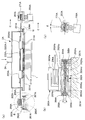
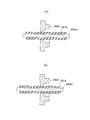
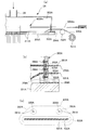
- FIG.1 (a) shows the example which spaced apart the masking unit
- FIG.1 (b) shows the example which made the masking unit approach.
- Show. 2 (a) is a cross-sectional view taken along the line II-II in FIG. 1
- FIG. 2 (b) is a detailed view of a portion B in FIG. 2 (a)
- FIG. 2 (c) is a CC arrow in FIG.
- FIG. 3 is a cross-sectional view taken along arrow III-III in FIG. 1.
- 4 (a) is a cross-sectional view taken along the line IV-IV in FIG.
- FIG. 4 (b) is a partially enlarged view of FIG. 4 (a), and FIG. It is another partial enlarged view.
- 5A is a cross-sectional view taken along the line IV-IV in FIG. 1 when using a spray
- FIG. 5B is a partially enlarged view of FIG. 5A
- FIG. 6A is an enlarged view of the VI part of FIG. 2
- FIG. 6B is a side view showing a part of FIG. 6A
- FIG. 7A is an enlarged sectional view of the wire seal when the spray is not used
- FIG. 7B is an enlarged sectional view of the wire seal when the spray is used. It is a schematic diagram for demonstrating the zero point adjustment of a masking unit.
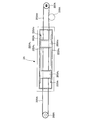
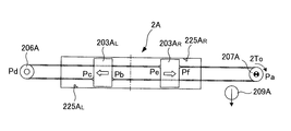
- FIG. 14A is an explanatory view showing the internal structure of the cooling device for hot-rolled steel sheets according to Example 2 of the present invention
- FIG. 14B is an explanatory view showing changes in the flow rate of cooling water in the plate width direction. .
- FIG. 14A is an explanatory view showing the internal structure of the cooling device for hot-rolled steel sheets according to Example 2 of the present invention
- FIG. 14B is an explanatory view showing changes in the flow rate of cooling water in the plate width direction. .
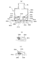
- FIG. 15A is an explanatory view showing the inside of a header structure having a masking sheet for blocking spraying outside the plate of the cooling device for hot-rolled steel sheets according to Example 3 of the present invention
- FIG. (A) The elements on larger scale
- FIG.15 (c) is a side view which shows a part of FIG.15 (b).
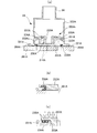
- FIG. 16A is an explanatory view showing the inside of a header structure having another masking unit of the cooling device for a hot-rolled steel sheet according to Embodiment 3 of the present invention
- FIG. 16B is a portion of FIG.
- FIG. 16C is an enlarged view
- FIG. 16C is a side view showing a part of FIG.
- the hot-rolled steel sheet cooling device continuously conveys the hot-rolled steel sheet 1 in a horizontal direction (hereinafter referred to as a steel sheet conveying direction X) indicated by an arrow X in FIG.
- the hot-rolled steel sheet 1 is cooled by spraying water from the lower spray headers 2A, 2B while being opposed to the upper and lower sides of the hot-rolled steel sheet 1.
- the spray header 2A and 2B have a generally vertically symmetrical structure, the upper spray header 2A will be described below as an example.
- the upper spray header 2 ⁇ / b> A has a width along the steel plate conveyance direction X and the width direction of the hot-rolled steel plate 1 indicated by the arrow Y in FIG. 1 (hereinafter referred to as the steel plate width direction Y).
- two masking units 203A L and 203A R arranged so as to be able to move toward and away from each other along the steel plate width direction Y (hereinafter, upstream of the steel plate conveyance direction X).
- the unit 203A R is referred to as a “right masking unit 203A R ”, and is collectively referred to as a “masking unit 203A L, R ”).
- the spray plate 201 ⁇ / b> A has a cooling water injection hole that communicates the inside and outside of the spray header 2 ⁇ / b> A in a desired range in the steel plate conveyance direction X and in a range corresponding to the maximum plate width of the hot-rolled steel plate 1 in the steel plate width direction Y.
- a number 211A (see FIG. 2A) is arranged at a predetermined pitch. That is, the cooling device for hot-rolled steel sheets according to the present example is a porous nozzle.
- the spray header body 202A has a flange 221A corresponding to the outer periphery of the spray plate 201A, and the flange 221A is closely fixed to the spray plate 201A via an elastic body 204A such as rubber packing. .
- the spray plate 201A and the spray header body 202A have a structure that can be disassembled.
- a cooling water supply pipe 3A is connected to the center of the surface of the spray header main body 202A facing the spray plate 201A, and the spray header main body is connected from a cooling water supply source (not shown) via the cooling water supply pipe 3A. High-pressure cooling water is supplied to the section 202A.
- the guide rails 222A U extending along the steel plate width direction Y to the side of the upstream side and downstream side of the steel plate conveyance direction X, is 222A L
- the guide rails 222A U positioned upstream in the steel plate conveying direction X are referred to as “upstream guide rails 222A U ” and the guide rails 222A L positioned upstream in the steel plate conveying direction X are referred to as “downstream guide rails 222A.
- L and collectively referred to as” guide rail 222A U, L ").
- the masking units 203A L and R are respectively disposed in the hollow portions formed by the spray plate 201A and the spray header main body 202A with the longitudinal direction along the steel plate conveyance direction X. More specifically, the masking units 203A L and R are formed so as to face the cooling water injection holes 211 of the spray plate 201 in a predetermined length in the steel plate width direction Y and across the entire area in the steel plate conveyance direction X. Has been.
- the masking unit 203A L, R is supported by the upstream guide rail 222A U and the downstream guide rail 222A L on the upstream side and the downstream side in the steel plate conveyance direction X, respectively , and the steel plate width direction along the guide rails 222A U, L.
- Y is configured to be movable.
- the shape of the spray header 201A on the spray header body 202A side is a flat surface without projections that interfere with the masking units 203AL , R.
- the positioning stopper 225A L positioned on the left side when viewed from the upstream side in the direction X is the “left positioning stopper 225A L ”, and the positioning stopper 225A R positioned on the right side when viewed from the upstream side in the steel sheet conveyance direction X is the “right positioning stopper 225A R. ”And generically referred to as“ positioning stopper 225A L, R ”).
- the positioning stoppers 225A L and R are provided for adjusting the zero point of the masking units 203A L and R, which will be described in detail later.
- the masking units 203A L and R are in contact with the positioning stoppers 225A L and R , respectively. when, are positioned such that the distance from the center of the distance and the steel plate width direction Y from the center of the steel plate width direction Y to the left masking unit 203A L to the right masking unit 203A R equal.
- the above-described movement of the masking units 203A L, R in the steel plate width direction Y is performed on the outer side of the upper spray header 2A and on the support rollers 206A disposed on both sides of the upper spray header 2A in the steel plate width direction Y, respectively.
- This is performed by the driving roller 207A and the supporting roller 206A and the wire 205A L and the wire 205A R wound around the driving roller 207A (hereinafter, the wire 205A L wound around the supporting roller 206A is referred to as “the left wire 205A L. ”,
- the wire 205A R wound around the drive roller 207A is referred to as“ right wire 205A R ”, and is collectively referred to as“ wire 205A L, R ”).
- Left wire 205A L has one end fixed to a surface of the support rollers 206A side of the left masking unit 203A L through the spray header main body 202A, the other end through a spray header body portion 202A and the left masking unit 203A L It is fixed to the surface of the right masking unit 203A R on the support roller 206A side.
- One end of the right wire 205A R penetrates the spray header body 202A and is fixed to a position facing the other end of the left wire 205A L on the surface of the right masking unit 203A R on the driving roller 207A side. is fixed at a position facing the one end of the left wire 205A L be a surface of the driving roller 207A side in the left masking unit 203A L through the spray header body portion 202A and the right masking unit 203A R. It is assumed that the right wire 205A R is configured not to slip with respect to the driving roller 207A by being wound around the driving roller 207A by a half or more.
- the masking units 203A L, R can move relatively close to and away from each other along the guide rails 222A U, L with the rotation of the drive roller 207A.
- the driving roller 207A is rotated clockwise
- the masking units 203A L, R are moved away from each other
- the support roller 206A is rotated counterclockwise
- the masking units 203A L, R are mutually moved. Move to approach.
- the support roller 206A is supported on the fixed base 261A via the slide base 262A and the roller holder 263A so that the axial direction is parallel to the vertical direction.
- the fixed base 261A is fixed to a structure such as a frame (not shown) that supports the upper spray header 2A.
- two bearing boxes 265A and 265A having bearings 264A and 264A, respectively, are installed apart along the steel plate width direction Y.
- a screw shaft 266A is rotatably supported on the bearings 264A and 264A.
- the slide base 262A is a concave member having a concave portion 262Aa and convex portions 262Ab and 262Ac located on both sides of the concave portion 262Aa in the steel plate width direction Y, and is on the fixed base 261A and has two bearing boxes 265A and 265A. It is placed between.
- a screw shaft 266A passes through the convex portions 262Ab and 262Ac.
- a screw hole 262Ad is formed in one of the convex portions 262Ab (left side in FIG. 2B), and the screw shaft 266A is screwed into the screw hole 262Ad.
- a through hole 262Ae is formed in the other convex portion 262Ac (right side in FIG. 2B), and a screw shaft 266A is inserted into the through hole 262Ae.
- the roller holder 263A is integrally provided with support portions 263Aa and 263Ab that respectively support the shaft ends of the support roller 206A, and a protrusion 263Ac that protrudes downward from the support portion 263Ab.
- the roller holder 263A is supported by the protrusions 262Ab and 262Ac of the slide base 262A in a state where the protrusion 263Ac is inserted into the recess 262Aa of the slide base 262A.
- a gap is provided between the lower surface of the protrusion 263Ac and the bottom surface of the recess 262Aa of the slide base 262A.
- a through hole 263Ad is formed in the protrusion 263Ac, and the screw shaft 266A is inserted into the through hole 263Ac. ing.
- a load cell 267A is disposed between the protruding portion 263Ac and the other convex portion 262Ac.
- the load cell 267A measures the pressure between the protrusion 263Ac and the protrusion 262Ac.
- the slide base 262A moves along the steel plate width direction Y by the action of the screw hole 262Ad screwed to the screw shaft 266A, and accordingly the roller holder 263A.
- the support roller 206A is configured to move along the steel plate width direction Y integrally with the slide base 262A.
- the driving roller 207A is supported by a roller holder 271A as shown in FIG.
- a motor 208A that rotates the drive roller 207A is connected to one shaft end of the drive roller 207A.
- the roller holder 271A is fixed to a structure such as a frame (not shown) that supports the upper spray header 2A, and the axial direction is slightly inclined with respect to the vertical direction as shown in FIG. 2 (c). (Inclination angle ⁇ ).
- the inclination angle ⁇ is set so that the state of the right wire 205A R is equal between the upstream side and the downstream side in the steel plate transport direction X when the right wire 205A R is wound around the drive roller 207A by more than a half turn (steel plate transport direction X Are set so that the position of the right wire 205A R is horizontal) on the upstream side and the downstream side.
- the member 209A shown in FIG. 3 is a tension applying roll provided so as to be movable between a position where the right wire 205A R is pressed and a position where the right wire 205A R is separated.
- a through hole 233A penetrating in the vertical direction is formed on the center side in the steel plate conveyance direction X of the holder portion 231A, and is an upper surface of the holder portion 231A on the upstream side and the downstream side in the steel plate conveyance direction X of the through hole 233A.
- a ditch 234A having a depth d extending along the steel plate width direction Y is formed.
- An elastic body 235A that can be elastically deformed at least in the vertical direction of height D (D> d) along the width direction Y of the steel plate is placed in the concave groove 234A.
- the elastic body 235A for example, a cylindrical member or a spring or the like whose axial center is directed along the steel plate width direction Y is used.
- the shielding plate 232A is opposed to the cooling water injection hole 211 in a predetermined length in the steel plate width direction Y and across the entire region in the steel plate conveyance direction X, and includes a connecting portion 236A inserted into the through hole 233A. Via the contact portion 237A that contacts the upper portion of the elastic body 235A.
- the shielding plate 232A is provided with a planar seal 238A in an annular shape (see FIG. 3) along the outer peripheral edge of the surface facing the spray plate 201A.
- the flat seal 238A is formed in a substantially V shape in cross-section (more specifically, a katakana “f” shape), and is attached to the shielding plate 232A so that the release portion faces the outside of the shielding plate 232A. Is fixed to the shielding plate 232A, while the lower part is a free end.
- the left masking unit 203A L is abutting portion by the elastic force of the elastic member 235A at the time of spray not used as shown in FIG. 4 (a state in which water pressure is not applied) 237A, the shielding plate 232A via the connecting portion 236A is While being pushed up, the shielding plate 232A and the flat seal 238A are separated from the spray plate 201A.
- the shielding plate 232A is pushed down by the water pressure, and the elastic body.
- the seal structure of the wires 205AL , R will be described with reference to FIGS.
- the right wire 205A R is covered with a covering seal 281A made of an elastic body (for example, NBR), and is slidably inserted into a through hole 223A formed in the spray header body 202A.
- the through hole 223A is formed such that the inner side in the width direction Y of the steel plate is larger in diameter than the outer side, and a cylindrical wire made of a highly rigid body such as a metal such as Teflon (registered trademark) or stainless steel in the large diameter portion.
- a seal 282A is inserted.
- the wire seal 282A is fixed by an annular cover plate 283A that covers the outer peripheral side of the inner surface of the wire seal 282A in the width direction Y of the steel plate.
- the cover plate 283A is fixed to the spray header main body 202A by fixing bolts 209A.
- the wire seal 282A has an inner diameter in the width direction Y of the steel plate that is substantially the same as the outer diameter of the covering seal 281A, and the surface facing the covering seal 281A has an arc shape in cross section. Is formed. Furthermore, it has the taper part which an internal diameter becomes wide as it goes to the outer side of the steel plate width direction Y.
- the covering seal 281A and the wire seal 282A are in line contact (point contact when viewed in cross section) when the spray is not used, as shown in FIG. 7A, while as shown in FIG. 7B.
- the taper portion of the wire seal 282A is deflected toward the outside in the steel plate width direction Y due to water pressure, and the interference to the covering seal 281A is increased.
- the wire seal 282A can minimize friction with the covering seal 281A when the masking unit 203AL , R is moved when the spray is not used.
- FIG. 7B when the spray is used, it is possible to prevent the cooling water from leaking from the through-hole 223A by securing a margin for the covering seal 281A.
- the wire seal 282A applies a certain pressure to the covering seal 281A covering the right wire 205A R irrespective of the action of water pressure, and selects the material and shape (thickness etc.) depending on the magnitude of the water pressure used. Shall be. This also applies to the left wire 205A L.
- the masking unit 203AL , R constitutes a mask member
- the guide rail 222AU , L constitutes a guide rail
- the holder portion 231A supports the mask member.
- the shielding plate 232A and the flat seal 238A constitute a shielding body
- the motor 208A constitutes the driving source
- the supporting roller 206A constitutes the driven roller
- R and the covering seal 281A constitute a first moving means
- the wire seal 282A constitutes a second sealing member
- the load cell 267A constitutes a load measuring means
- the slide base 262A and the screw shaft 266A constitute a second moving member. It constitutes a moving means.
- the spray header 2 is disassembled and reassembled by maintenance or the like , and then the position adjustment (hereinafter referred to as “zero point adjustment”) of the masking units 203AL , R is performed.
- the zero point adjustment is performed by the following method. That is,
- the motor 208A rotates the driving roller 207A with a constant low torque 2T 0
- the left masking unit 203A L contacts the left positioning stopper 225A L or the right masking unit 203A R contacts the right positioning stopper 225A R.
- a constant tension (2T 0 in this case) is applied to the right wire 205A R by the contact
- the driving roller 207A stops rotating without further rotation.
- the left masking unit 203A L is in contact with the left positioning stopper 225A L, or right-masking unit 203A R Is in contact with the right positioning stopper 225A R.
- the right masking unit 203A distance from the center of the steel plate width direction Y of R is greater than the distance from the center of the steel plate width direction Y of the left masking unit 203A L, than the left masking unit 203A L abuts against the left positioning stopper 225A L
- the process proceeds to (3) described later.
- the load acting on the left wire 205A L is the same value as the torque of the drive roller 207A. as shown in, longer than the distance from the center distance from the center of the steel plate width direction Y of the steel sheet width direction Y of the right masking unit 203A R left masking unit 203A L, right masking unit 203A R right positioning left masking unit 203A L ahead abuts against the stopper 225A R moves to the processing of later it is determined that contact with the left positioning stopper 225A L (3 ').
- the support roller 206A is moved to the position, the rotation of the screw shaft 266A is stopped, and the position of the slide base 262A is fixed so that the position of the slide base 262A is fixed, as shown in FIG. 2B, between the projection 262Ac and the projection 263Ac.
- a spacer 268A is attached.
- the masking unit 203AL , R can be incorporated in the upper spray header 2A and the position of the masking unit 203AL , R can be visually confirmed. Even without this, the zero point adjustment of the masking units 203AL , R can be performed with high accuracy.
- the zero point adjustment described above is performed as necessary, for example, after disassembling the upper spray header 2A for maintenance.
- the hot-rolled steel sheet is cooled in a state where the positions of the masking units 203A R and L are adjusted by adjusting the zero point.
- the motor 208A when it is desired to reduce the supercooling of the plate end portion of the hot rolled steel sheet 1 with respect to the width direction Y of the hot rolled steel sheet 1, when the spray is not used, the motor 208A is driven to rotate the driving roller 207A.
- the masking unit 203A L, R is moved to a position facing the plate end of the hot-rolled steel sheet 1.
- the motor 208A when it is desired to reduce the supercooling of the central portion of the hot rolled steel sheet 1 in the width direction Y of the steel sheet, when the spray is not used, the motor 208A is driven to rotate the driving roller 207A and the masking units 203AL , R are hot rolled. It moves to the position which opposes the center part of the steel plate width direction Y of the steel plate 1.
- the masking unit 203AL does not come into contact with the spray plate 201A during the movement of the L, R. It is possible to extend the life by suppressing the deterioration of the shielding plate 232A and the flat seal 238A.
- the covering seal 281A covering the wire 205A comes into sliding contact with the wire seal 282A.
- the contact between the covering seal 281A and the wire seal 282A is a line contact, the covering seal 281A and the wire seal 282A are caused by friction. Deterioration can be suppressed, and the life of the covering seal 281A and the wire seal 282A can be extended.
- the taper portion of the wire seal 282A is deflected outwardly in the steel sheet width direction Y by water pressure and pressed against the covering seal 281A, and from the inside of the spray header 2A by the contact pressure between the covering seal 281A and the wire seal 282A. Prevents cooling water from leaking outside.
- the cooling water is sprayed to the center of the hot-rolled steel sheet 1 as shown in FIG. It is possible to prevent the cooling water from being sprayed to the plate end portion, and it is possible to reduce the supercooling of the plate end portion and make the temperature distribution in the width direction of the hot-rolled steel sheet 1 uniform. Further, when it is desired to reduce the supercooling of the central portion of the hot-rolled steel sheet 1 in the width direction Y of the steel sheet, while injecting cooling water to the plate end side of the hot-rolled steel sheet 1 as shown in FIG. It is possible to prevent the cooling water from being sprayed to the center portion of the hot-rolled steel sheet 1 and to reduce the supercooling of the center part of the plate to make the temperature distribution in the width direction of the hot-rolled steel sheet 1 uniform. It becomes.
- the masking units 203A L and R are cooled by the cooling water inside the spray header 2A, so that there is no possibility of thermal deformation due to the heat of the hot-rolled steel sheet 1.
- the cooling water injection hole 211A of the spray plate 201A can be directly closed by the masking unit 203A L, R inside the spray header 201A, the cooling water in the spray header 2A can be blocked by the masking unit 203A L, R. Since water can be uniformly injected toward the hot-rolled steel sheet 1 from the cooling water injection holes 211A outside the covered region, the water on the plate efficiently flows at both ends in the width direction of the hot-rolled steel plate 1 The water drainage route can be stabilized.
- the number of masking units provided in one spray header 2A is not limited to two.
- it may be configured such that the length of the steel plate width direction Y can be changed in a sliding manner.
- the right wire 205A R by winding over half a right wire 205AR the drive roller 207A is configured such slippage does not occur with respect to the driving roller 207A, tension acts on the right wire 205A R
- Other methods may be used as long as the structure allows the right wire 205A R to be pressed against the driving roller 207A even in a state where it is not.
- the support roller 206A, the drive roller 207A, the wire 205A, and the covering seal 281A are used as the first moving means, but a rope may be used instead of the wire 205A.
- the load cell 267A is used as the load detecting means.
- a spring 269A may be used instead of the load cell 267A, and various modifications are possible without departing from the spirit of the present invention. Can be changed.
- the upper spray header 2A and the lower spray header 2B, a masking unit 203B L under spray header 2B, 203B R is a masking unit 203A L of the upper spray header 2A, with respect to R, the elastic member to form a groove
- the mounting position is on the surface facing the shielding plate of the holder portion, and therefore detailed description of the lower spray header 2B is omitted.
- Masking unit 203B L under a spray header 2B even when applying 203B R, as with the upper surface of the hot rolled steel sheet 1 by the upper spray header 2A cooling, with respect to the lower surface of the cooling of hot-rolled steel sheet 1, the width of the hot-rolled steel sheet 1 It is possible to block the jet of cooling water from below that obstructs the flow of water on the plate at both ends in the direction, stabilize the drainage path of the plate water, and reduce overcooling of the desired part, The temperature distribution in the steel plate width direction Y can be made uniform while suppressing the increase in size.
- the size of the device is suppressed and the lengths of the masking units 203A L, R , 203B L, R are reduced. It is possible to make the temperature distribution in the width direction of the hot-rolled steel sheet uniform while extending the life, and the masking units 203A L, R , 203B L, R are incorporated in the spray headers 2A, 2B. Even in this case , the position adjustment of the masking units 203A L, R can be performed with high accuracy.
- FIG. 14 Based on FIG. 14, the detail of the cooling apparatus of the hot-rolled steel plate which concerns on Example 2 of this invention is demonstrated.
- the hot-rolled steel sheet cooling device according to the present embodiment is shown in FIG. 1 to FIG. 13 in place of the masking unit 203AL , R of the hot-rolled steel plate cooling device according to the first embodiment described above and shown in FIG.
- 503A L and 503A R are used.
- Other configurations are the same as those of the first embodiment, and hereinafter, members having the same action are denoted by the same reference numerals and redundant description is omitted, and different points will be mainly described.
- the masking units 503A L and 503A R have the length in the steel plate width direction Y changing along the steel plate conveyance direction X.
- the masking units 503A L and 503A R are formed in a generally trapezoidal shape when viewed from above so that the mutual distance becomes narrower from the upstream side in the steel plate conveyance direction X toward the downstream side in the steel plate conveyance direction X. Yes.
- the flow rate of cooling water is large on the upstream side in the steel sheet transport direction X, and on the downstream side in the steel sheet transport direction X.
- the flow rate of the cooling water can be reduced, and in addition to the effects of the first embodiment described above, the controllability of the cooling capacity in the steel sheet width direction Y can be further improved. This is the same when applied to the lower spray header 2B.
- a hot-rolled steel sheet cooling device uses a masking sheet 630A shown in FIG. 15 instead of the flat seal 238A of the hot-rolled steel plate cooling device according to the first embodiment shown in FIGS. It is an example.
- Other configurations are the same as those of the first embodiment, and hereinafter, members having the same action are denoted by the same reference numerals and redundant description is omitted, and different points will be mainly described.
- the masking sheet 630A is formed into a sheet masking unit 203A L, said from R masking unit 203A L, coolant injection holes over the entire area of the outer steel sheet width direction Y of the R 211A is covered and can be wound by a winder 701A.
- reference numeral 702A in FIG. 15A denotes a roller for guiding the masking sheet 630A to the winder 701A.
- the masking sheet 630A is formed on the spray header main body 202A by covering, for example, a plate body 361A formed of a thin plate of iron with a covering seal 632A made of an elastic body.
- the through hole 224A is slidably inserted.
- the through hole 224A is formed such that the inner side in the steel plate width direction Y is larger in diameter than the outside, and a cylindrical flat seal 633A made of, for example, Teflon is fitted into the large diameter portion.
- the flat seal 633A is fixed by an annular cover plate 634A that covers the outer peripheral side of the inner surface of the flat seal 633A in the steel plate width direction Y.
- the cover plate 634A is fixed to the spray header main body 202A by fixing bolts 209A.
- the flat seal 633A has an inner diameter that is substantially the same as the outer diameter of the covering seal 632A, and a surface facing the covering seal 632A is formed in an arc shape in cross section. Furthermore, it has the taper part which an internal diameter becomes wide as it goes to the outer side of the steel plate width direction Y.
- the covering seal 632A and the flat seal 633A are in line contact (point contact in cross section) when the spray is not used, as with the wire seal 282A shown in FIG.
- the taper portion of the flat seal 633A bends toward the outside in the steel plate width direction Y by water pressure and is pressed against the covering seal 632A.
- the flat seal 633A is in contact with the covering seal 632A when the spray is not used, and the cross-sectional viewpoint contact is made, and when the masking unit 203AL , R is moved, the friction with the covering seal 632A is minimized.
- the cooling water can be prevented from leaking from the through hole 223A by being pressed against the covering seal 632A.
- the masking sheet 630A constitutes a shield
- the flat seal 633A constitutes the first seal member
- a hot-rolled steel sheet 1 having a narrow plate width.
- the cooling water injection holes 211A are disposed outside the masking units 203AL , R in the width direction Y of the steel sheet. Even if there is, the masking sheet 630A can close the cooling water injection holes 211 outside the masking units 203AL , R in the steel plate width direction Y, so that the cooling water can be saved.
- the taper portion of the flat seal 633A is outside the steel sheet width direction Y by water pressure. It is possible to prevent the cooling water from leaking from the inside of the upper spray header 2A to the outside by the contact pressure between the covering seal 632A and the flat seal 633A. This is the same when applied to the lower spray header 2B.
- the cover plate 283A and the cover plate 634A are separated from each other.
- the masking sheet 630A is formed on the spray header main body 202A that is slidably inserted.
- the formed through hole 224A is formed in the vicinity of the through hole 223A formed in the spray header main body 202A through which the wire 205A is slidably inserted, and the wire seal 282A and the flat seal 633A are fixed by one cover plate 635A. You may make it do.
- reference numeral 603A R denotes a masking unit
- reference numeral 703A denotes a guide block for guiding the masking sheet 630A to the through hole.
- the present invention is suitable for application to a hot-rolled steel plate cooling device and a mask member position adjusting method thereof.
Landscapes
- Engineering & Computer Science (AREA)
- Mechanical Engineering (AREA)
- Details Or Accessories Of Spraying Plant Or Apparatus (AREA)
- Heat Treatment Of Strip Materials And Filament Materials (AREA)
Abstract
スプレーヘッダー(2A)が、本体部(202A)の内周面に設けられ熱延鋼板(1)の板幅方向に沿って延びるガイドレール(222AU,L)と、ガイドレール(222AU,L)に沿って移動するマスキングユニット(203AL,R)とを内蔵し、マスキングユニット(203AL,R)が、ガイドレール(222AU,L)に沿って移動可能に設けられた支持体(231A)と、支持体(231A)に弾性体(235A)を介して支持される遮蔽板(232A)とを有し、遮蔽板(232A)が、水圧が作用していないときはスプレー板(201A)から離反し、弾性体(235A)が圧縮変形されることによりスプレー板(201A)に押圧されて所望の冷却水噴射孔を塞ぐ構成とした。
Description
本発明は、熱延鋼板の冷却装置及びそのマスク部材位置調整方法に関する。
従来、熱間圧延した高温の熱延鋼板を冷却する、又は熱延鋼板を再加熱して熱処理を行う工程において熱延鋼板を冷却する冷却装置には、熱延鋼板の幅方向の温度分布を均一化することを目的として、熱延鋼板の冷却を行う冷却装置のヘッダーに取り付けられる冷却ノズルと熱延鋼板との間に、熱延鋼板の幅方向に移動可能に構成されて冷却ノズルから熱延鋼板のエッジ付近に供給される冷却水を遮蔽する遮蔽体を設けたものがある(例えば、特許文献1~3参照)。
また、ヘッダーを、冷却水噴射ノズルを有する外側冷却ヘッダーと、圧空噴射ノズルを有する内側冷却ヘッダーとからなる二重構造とし、内側冷却ヘッダーの両端部にヘッダー長手方向に移動して圧空の噴射を遮断するマスク部材を内嵌し、冷却水噴射幅を制御するものもある(例えば、特許文献4参照)。
しかしながら、上述した特許文献1~3に記載された冷却装置にあっては、遮蔽体が冷却ノズルと熱延鋼板との間に設けられるため、遮蔽体を移動可能とし且つ設定位置に固定するための構造および遮蔽体によって遮蔽した冷却水を逃がすための水圧に耐える構造が必要となり、遮蔽板の周辺構造物が大型化かつ複雑化するという問題があった。また、遮蔽体を冷却ノズルと高温の熱延鋼板との間に配設することにより該遮蔽体が熱変形を生じるおそれもあった。更に、遮蔽体を熱延鋼板の下面側を冷却する下ヘッダーの冷却ノズルと熱延鋼板との間に設置する場合には、熱延鋼板と干渉しても損傷しない強固なものにしなければならず、大型化が避けられないという問題もあった。
また、上述した特許文献4に記載された冷却装置にあっては、マスク部材の材質として、気密性を保つために天然ゴム、シリコン材、ウレタン材等が選定され、かつ、マスク部が同時に相反する方向に自在に往復移動できる仕組みとなっており、マスク部材を移動させる際、マスク部材が内側冷却ヘッダーに摺接することによりマスク部材が摩耗し劣化しやすくなる問題があった。
このようなことから本発明は、装置の大型化を抑制するとともにマスク部材の長寿命化を図りつつ、熱延鋼板の幅方向の温度分布を均一化することを可能とした熱延鋼板の冷却装置及びそのマスク部材位置調整方法を提供することを目的とする。
上記の課題を解決するための第1の発明に係る熱延鋼板の冷却装置は、
搬送方向に移動する熱延鋼板の上下に多数の冷却水噴射孔を有するスプレー板と当該スプレー板を覆う箱状の本体部とを具備するスプレーヘッダーを対向配置し、前記冷却水噴射孔から前記熱延鋼板に冷却水を吹き付けることによって前記熱延鋼板の冷却を行う熱延鋼板の冷却装置において、
前記スプレーヘッダーが、前記本体部の内周面に設けられ前記熱延鋼板の板幅方向に沿って延びる案内レールと、前記案内レールに沿って移動するマスク部材とを内蔵し、
前記マスク部材が、前記案内レールに沿って前記熱延鋼板の板幅方向に移動可能に設けられた支持体と、少なくとも上下方向に弾性変形可能な弾性体を介して前記支持体に支持される遮蔽体とを有し、
前記遮蔽体が、水圧が作用していないときは前記スプレー板から離反し、水圧が作用しているときは前記弾性体が圧縮変形されることにより前記スプレー板に押圧されて所望の前記冷却水噴射孔を塞ぐ
ことを特徴とする。
搬送方向に移動する熱延鋼板の上下に多数の冷却水噴射孔を有するスプレー板と当該スプレー板を覆う箱状の本体部とを具備するスプレーヘッダーを対向配置し、前記冷却水噴射孔から前記熱延鋼板に冷却水を吹き付けることによって前記熱延鋼板の冷却を行う熱延鋼板の冷却装置において、
前記スプレーヘッダーが、前記本体部の内周面に設けられ前記熱延鋼板の板幅方向に沿って延びる案内レールと、前記案内レールに沿って移動するマスク部材とを内蔵し、
前記マスク部材が、前記案内レールに沿って前記熱延鋼板の板幅方向に移動可能に設けられた支持体と、少なくとも上下方向に弾性変形可能な弾性体を介して前記支持体に支持される遮蔽体とを有し、
前記遮蔽体が、水圧が作用していないときは前記スプレー板から離反し、水圧が作用しているときは前記弾性体が圧縮変形されることにより前記スプレー板に押圧されて所望の前記冷却水噴射孔を塞ぐ
ことを特徴とする。
また、第2の発明に係る熱延鋼板の冷却装置は、第1の発明において、
前記遮蔽体は、板状に形成されて前記スプレー板に対向する遮蔽板と、断面視概ねV字状に形成され解放部が外側を向くように前記遮蔽板の外周縁に固着された平面シールとからなる
ことを特徴とする。
前記遮蔽体は、板状に形成されて前記スプレー板に対向する遮蔽板と、断面視概ねV字状に形成され解放部が外側を向くように前記遮蔽板の外周縁に固着された平面シールとからなる
ことを特徴とする。
また、第3の発明に係る熱延鋼板の冷却装置は、第1の発明において、
前記遮蔽体は、金属からなる薄板と、該薄板を被覆する弾性体とからなり、前記スプレーヘッダーの外側で巻取可能に構成されて前記マスク部材の直下から前記熱延鋼板の板幅方向外側にある全ての前記冷却水噴射孔を覆うマスキングシートであり、
前記マスキングシートは、前記スプレーヘッダーに形成された貫通孔に、環状に形成された第一のシール部材を介して挿通され、
前記第一のシール部材は、水圧が作用していないときは前記薄板を被覆する弾性体に線接触する一方、水圧が作用しているときは前記薄板を被覆する弾性体を押圧する
ことを特徴とする。
前記遮蔽体は、金属からなる薄板と、該薄板を被覆する弾性体とからなり、前記スプレーヘッダーの外側で巻取可能に構成されて前記マスク部材の直下から前記熱延鋼板の板幅方向外側にある全ての前記冷却水噴射孔を覆うマスキングシートであり、
前記マスキングシートは、前記スプレーヘッダーに形成された貫通孔に、環状に形成された第一のシール部材を介して挿通され、
前記第一のシール部材は、水圧が作用していないときは前記薄板を被覆する弾性体に線接触する一方、水圧が作用しているときは前記薄板を被覆する弾性体を押圧する
ことを特徴とする。
また、第4の発明に係る熱延鋼板の冷却装置は、第1から第3のいずれか一つの発明において、
前記遮蔽体の形状は、水量分布を幅方向に勾配をもって変化させるように、前記熱延鋼板の板幅方向に沿った長さが前記熱延鋼板の搬送方向に沿って変化する
ことを特徴とする。
前記遮蔽体の形状は、水量分布を幅方向に勾配をもって変化させるように、前記熱延鋼板の板幅方向に沿った長さが前記熱延鋼板の搬送方向に沿って変化する
ことを特徴とする。
また、第5の発明に係る熱延鋼板の冷却装置は、第1から第4のいずれか一つの発明において、
前記スプレーヘッダーの外部に駆動源を有し、前記マスク部材を前記熱延鋼板の板幅方向に移動させる第一の移動手段を備える
ことを特徴とする。
前記スプレーヘッダーの外部に駆動源を有し、前記マスク部材を前記熱延鋼板の板幅方向に移動させる第一の移動手段を備える
ことを特徴とする。
また、第6の発明に係る熱延鋼板の冷却装置は、第5の発明において、
前記第一の移動手段は、前記スプレーヘッダーの外側であり前記熱延鋼板の板幅方向の両側に各々設置された駆動ローラ及び非駆動ローラと、前記駆動ローラ及び非駆動ローラに巻きかけられて両端が前記マスク部材に固定されたワイヤとから構成され、
前記ワイヤは、弾性体により被覆され、前記スプレーヘッダーに形成された貫通孔に、環状に形成された第二のシール部材を介して挿通され、
前記第二のシール部材は、水圧が作用していないときは前記ワイヤを被覆する弾性体に線接触する一方、水圧が作用しているときは前記ワイヤを被覆する弾性体を押圧して該弾性体に密着する
ことを特徴とする。
前記第一の移動手段は、前記スプレーヘッダーの外側であり前記熱延鋼板の板幅方向の両側に各々設置された駆動ローラ及び非駆動ローラと、前記駆動ローラ及び非駆動ローラに巻きかけられて両端が前記マスク部材に固定されたワイヤとから構成され、
前記ワイヤは、弾性体により被覆され、前記スプレーヘッダーに形成された貫通孔に、環状に形成された第二のシール部材を介して挿通され、
前記第二のシール部材は、水圧が作用していないときは前記ワイヤを被覆する弾性体に線接触する一方、水圧が作用しているときは前記ワイヤを被覆する弾性体を押圧して該弾性体に密着する
ことを特徴とする。
また、第7の発明に係る熱延鋼板の冷却装置は、第6の発明において、
前記スプレーヘッダーは、前記熱延鋼板の板幅中央部を挟んで対称に配置される複数の前記マスク部材を内蔵し、
前記第一の移動手段は、前記熱延鋼板の板幅方向の中央部を挟んで対向する前記マスク部材を、相互に連動して接近離反移動させる
ことを特徴とする。
前記スプレーヘッダーは、前記熱延鋼板の板幅中央部を挟んで対称に配置される複数の前記マスク部材を内蔵し、
前記第一の移動手段は、前記熱延鋼板の板幅方向の中央部を挟んで対向する前記マスク部材を、相互に連動して接近離反移動させる
ことを特徴とする。
また、第8の発明に係る熱延鋼板の冷却装置は、第6又は第7の発明において、
前記第二のシール部材は、高剛性体からなり、水圧作用とは関係なくワイヤを被覆する弾性体に一定の押圧を与え密着するとともに、使用する水圧の大きさによって選択される
ことを特徴とする。
前記第二のシール部材は、高剛性体からなり、水圧作用とは関係なくワイヤを被覆する弾性体に一定の押圧を与え密着するとともに、使用する水圧の大きさによって選択される
ことを特徴とする。
また、第9の発明に係る熱延鋼板の冷却装置は、第7又は第8の発明において、
前記マスク部材の前記熱延鋼板の板幅方向の移動を規制するストッパーと、
前記マスク部材が前記ストッパーに当接したことを検出する当接検出手段と、
前記非駆動ローラに巻きかけられたワイヤに作用する荷重を測定する荷重測定手段と、
前記非駆動ローラを前記熱延鋼板の板幅方向に移動させる第二の移動手段とを備える
ことを特徴とする。
前記マスク部材の前記熱延鋼板の板幅方向の移動を規制するストッパーと、
前記マスク部材が前記ストッパーに当接したことを検出する当接検出手段と、
前記非駆動ローラに巻きかけられたワイヤに作用する荷重を測定する荷重測定手段と、
前記非駆動ローラを前記熱延鋼板の板幅方向に移動させる第二の移動手段とを備える
ことを特徴とする。
また、第10の発明に係る熱延鋼板の冷却装置のマスク部材位置調整方法は、第9の発明において、
前記駆動ローラを回転させて前記熱延鋼板の板幅方向の中央部を挟んで対向する前記マスク部材を相互に離反する方向へ移動させ、
前記当接検出手段により少なくとも一方の前記マスク部材が前記ストッパーに当接したことを検出したら前記荷重測定手段による測定値が予め設定する値となるまで前記第二の移動手段により前記非駆動ローラを前記熱延鋼板の板幅方向に移動させる
ことを特徴とする。
前記駆動ローラを回転させて前記熱延鋼板の板幅方向の中央部を挟んで対向する前記マスク部材を相互に離反する方向へ移動させ、
前記当接検出手段により少なくとも一方の前記マスク部材が前記ストッパーに当接したことを検出したら前記荷重測定手段による測定値が予め設定する値となるまで前記第二の移動手段により前記非駆動ローラを前記熱延鋼板の板幅方向に移動させる
ことを特徴とする。
上述した本発明に係る熱延鋼板の冷却装置によれば、装置の大型化を抑制するとともにマスク部材の長寿命化を図りつつ、熱延鋼板の幅方向の温度分布を均一化することが可能となる。また、本発明に係る熱延鋼板の冷却装置のマスク部材位置調整方法によれば、マスク部材がスプレーヘッダーに内蔵された状態であってもマスク部材の位置調整を高精度に行うことができる。
以下、図面を参照しつつ本発明に係る熱延鋼板の冷却装置及びそのマスク部材位置調整方法について説明する。
図1から図13に基づいて本発明の実施例1に係る熱延鋼板の冷却装置及びそのマスク部材位置調整方法を詳細に説明する。
図1に示すように、本実施例に係る熱延鋼板の冷却装置は、高温の熱延鋼板1を図1中矢印Xで示す水平方向(以下、鋼板搬送方向Xという)へ連続的に搬送させつつ、該熱延鋼板1の上下に対向配置した上,下スプレーヘッダー2A,2Bから水を吹き付けることによって熱延鋼板1を冷却する設備である。上,下スプレーヘッダー2A,2B(以下、総称する場合はスプレーヘッダー2という)は概ね上下対称の構造となっているので、以下、上スプレーヘッダー2Aを例に説明する。
図1に示すように、本実施例に係る熱延鋼板の冷却装置は、高温の熱延鋼板1を図1中矢印Xで示す水平方向(以下、鋼板搬送方向Xという)へ連続的に搬送させつつ、該熱延鋼板1の上下に対向配置した上,下スプレーヘッダー2A,2Bから水を吹き付けることによって熱延鋼板1を冷却する設備である。上,下スプレーヘッダー2A,2B(以下、総称する場合はスプレーヘッダー2という)は概ね上下対称の構造となっているので、以下、上スプレーヘッダー2Aを例に説明する。
図1から図3に示すように、上スプレーヘッダー2Aは、鋼板搬送方向X及び図1中矢印Yで示す熱延鋼板1の幅方向(以下、鋼板板幅方向Yという)に沿ってそれぞれ幅方向及び長手方向を向けて配設された板状のスプレー板201Aと、該スプレー板201Aを覆う概ね箱状のスプレーヘッダー本体部202Aと、スプレー板201A及びスプレーヘッダー本体部202Aによって形成された中空部に配設され鋼板板幅方向Yに沿って相互に接近離反移動できるように配設された二つのマスキングユニット203AL,203ARとを具備している(以下、鋼板搬送方向Xの上流側から見て左側に位置するマスキングユニット203ALを「左マスキングユニット203AL」、鋼板搬送方向Xの上流側から見て右側に位置するマスキングユニット203ARを「右マスキングユニット203AR」と呼称し、総称する場合は「マスキングユニット203AL,R」と呼称する)。
スプレー板201Aには、鋼板搬送方向Xについては所望の範囲に、また鋼板板幅方向Yについては熱延鋼板1の最大板幅に対応する範囲にスプレーヘッダー2Aの内外を連通する冷却水噴射孔211A(図2(a)参照)が所定のピッチで多数配列されている。すなわち、本実施例に係る熱延鋼板の冷却装置は多孔式ノズルとなっている。
また、スプレーヘッダー本体部202Aには、スプレー板201Aの外周に対応してフランジ221Aが形成されており、このフランジ221Aがゴムパッキン等の弾性体204Aを介してスプレー板201Aに密着固定されている。換言すると、スプレー板201Aとスプレーヘッダー本体部202Aとは分解可能な構造となっている。
そして、スプレーヘッダー本体部202Aのスプレー板201Aに対向する面の中央部には冷却水供給管3Aが連結されており、図示しない冷却水供給源からこの冷却水供給管3Aを介してスプレーヘッダー本体部202Aに高圧の冷却水が供給されるようになっている。
図2及び図3に示すように、スプレーヘッダー本体部202Aの内部には、鋼板搬送方向Xの上流側及び下流側の側面に鋼板板幅方向Yに沿って延びるガイドレール222AU,222ALが設けられている(以下、鋼板搬送方向Xの上流側に位置するガイドレール222AUを「上流ガイドレール222AU」、鋼板搬送方向Xの上流側に位置するガイドレール222ALを「下流ガイドレール222AL」と呼称し、総称する場合は「ガイドレール222AU,L」と呼称する)。
また、マスキングユニット203AL,Rはそれぞれスプレー板201Aとスプレーヘッダー本体部202Aとによって形成された中空部に鋼板搬送方向Xに沿って長手方向を向けて配設されている。より具体的には、マスキングユニット203AL,Rはスプレー板201の冷却水噴射孔211に対して鋼板板幅方向Yについては所定の長さ、鋼板搬送方向Xについては全域にわたって対向するように形成されている。
このマスキングユニット203AL,Rは、鋼板搬送方向Xの上流側及び下流側が各々上流ガイドレール222AU及び下流ガイドレール222ALに支持されており、ガイドレール222AU,Lに沿って鋼板板幅方向Yに移動可能に構成されている。また、スプレー板201Aのスプレーヘッダー本体部202A側の形状は、マスキングユニット203AL,Rに干渉する突起物がない平坦面となっている。
上流ガイドレール222AUには後述する支持ローラ206A側に位置決めストッパー225ALが取り付けられ、下流ガイドレール222ALには後述する駆動ローラ207A側に位置決めストッパー225ARが取り付けられている(以下、鋼板搬送方向Xの上流側から見て左側に位置する位置決めストッパー225ALを「左位置決めストッパー225AL」、鋼板搬送方向Xの上流側から見て右側に位置する位置決めストッパー225ARを「右位置決めストッパー225AR」と呼称し、総称する場合は「位置決めストッパー225AL,R」と呼称する)。
位置決めストッパー225AL,Rは、後で詳述するマスキングユニット203AL,Rのゼロ点調整用に設けられたものであり、これら位置決めストッパー225AL,Rにそれぞれマスキングユニット203AL,Rが当接したときに、鋼板板幅方向Yの中心から左マスキングユニット203ALまでの距離と鋼板板幅方向Yの中心から右マスキングユニット203ARまでの距離とが等しくなるように位置決めされている。
上述したマスキングユニット203AL,Rの鋼板板幅方向Yの移動は、上スプレーヘッダー2Aの外側であって該上スプレーヘッダー2Aの鋼板板幅方向Yの両側に各々配設された支持ローラ206A及び駆動ローラ207Aと、これら支持ローラ206A及び駆動ローラ207Aにそれぞれ巻きかけられたワイヤ205AL及びワイヤ205ARとにより行われる(以下、支持ローラ206Aに巻きかけられたワイヤ205ALを「左ワイヤ205AL」、駆動ローラ207Aに巻きかけられたワイヤ205ARを「右ワイヤ205AR」と呼称し、総称する場合は「ワイヤ205AL,R」と呼称する)。
左ワイヤ205ALは一端がスプレーヘッダー本体部202Aを貫通して左マスキングユニット203ALの支持ローラ206A側の面に固定され、他端がスプレーヘッダー本体部202A及び左マスキングユニット203ALを貫通して右マスキングユニット203ARの支持ローラ206A側の面に固定されている。
右ワイヤ205ARは、一端がスプレーヘッダー本体部202Aを貫通して右マスキングユニット203ARの駆動ローラ207A側の面であって左ワイヤ205ALの他端に対向する位置に固定され、他端がスプレーヘッダー本体部202A及び右マスキングユニット203ARを貫通して左マスキングユニット203ALの駆動ローラ207A側の面であって左ワイヤ205ALの一端に対向する位置に固定されている。なお、右ワイヤ205ARは駆動ローラ207Aに半周以上巻きつけることにより、駆動ローラ207Aに対してすべりが生じないように構成されているものとする。
これにより、マスキングユニット203AL,Rは駆動ローラ207Aの回転に伴い、ガイドレール222AU,Lに沿って相対的に接近離反移動できるようになっている。本実施例では、駆動ローラ207Aを時計回りに回転させるとマスキングユニット203AL,Rが相互に離反するように移動し、支持ローラ206Aを反時計回りに回転させるとマスキングユニット203AL,Rが相互に接近するように移動する。
なお、図2(b)に示すように、支持ローラ206Aは固定ベース261A上にスライドベース262A及びローラホルダ263Aを介して軸方向が鉛直方向と平行になるように支持されている。
固定ベース261Aは上スプレーヘッダー2Aを支持する図示しないフレーム等の構造物に固定されている。この固定ベース261A上にはそれぞれベアリング264A,264Aを備えた二つのベアリングボックス265A,265Aが鋼板板幅方向Yに沿って離間して設置されている。ベアリング264A,264Aにはスクリューシャフト266Aが回動自在に支持されている。
固定ベース261Aは上スプレーヘッダー2Aを支持する図示しないフレーム等の構造物に固定されている。この固定ベース261A上にはそれぞれベアリング264A,264Aを備えた二つのベアリングボックス265A,265Aが鋼板板幅方向Yに沿って離間して設置されている。ベアリング264A,264Aにはスクリューシャフト266Aが回動自在に支持されている。
スライドベース262Aは、凹部262Aaとこの凹部262Aaの鋼板板幅方向Yの両側に位置する凸部262Ab,262Acとを有する凹状の部材であり、固定ベース261A上であって二つのベアリングボックス265A,265Aの間に載置されている。
凸部262Ab,262Acにはスクリューシャフト266Aが貫通している。具体的には、一方(図2(b)では左側)の凸部262Abにはネジ穴262Adが形成されこのネジ穴262Adにスクリューシャフト266Aが螺合している。また、他方(図2(b)では右側)の凸部262Acには貫通孔262Aeが形成されこの貫通孔262Aeにスクリューシャフト266Aが挿通されている。
凸部262Ab,262Acにはスクリューシャフト266Aが貫通している。具体的には、一方(図2(b)では左側)の凸部262Abにはネジ穴262Adが形成されこのネジ穴262Adにスクリューシャフト266Aが螺合している。また、他方(図2(b)では右側)の凸部262Acには貫通孔262Aeが形成されこの貫通孔262Aeにスクリューシャフト266Aが挿通されている。
ローラホルダ263Aは支持ローラ206Aの軸端をそれぞれ支持する支持部263Aa,263Abと、支持部263Abから下方に突出した突出部263Acとを一体的に備えている。ローラホルダ263Aは突出部263Acがスライドベース262Aの凹部262Aaに挿入された状態で、支持部263Abがスライドベース262Aの凸部262Ab,262Acに支持されている。突出部263Acの下面とスライドベース262Aの凹部262Aaの底面との間には隙間が設けられており、また、突出部263Acには貫通孔263Adが形成されこの貫通孔263Acにスクリューシャフト266Aが挿通されている。
さらに、突出部263Acと他方の凸部262Acとの間にはロードセル267Aが配設されている。ロードセル267Aは突出部263Acと凸部262Acとの間の圧力を測定するものである。
すなわち、本実施例では、スクリューシャフト266Aを回転させるとこのスクリューシャフト266Aに螺合するネジ穴262Adの作用によりスライドベース262Aが鋼板板幅方向Yに沿って移動し、これに伴ってローラホルダ263Aを介して支持ローラ206Aがスライドベース262Aと一体的に鋼板板幅方向Yに沿って移動するように構成されている。
また、駆動ローラ207Aは図2(a)に示すようにローラホルダ271Aに支持されている。そして、駆動ローラ207Aの一方の軸端には当該駆動ローラ207Aを回動させるモータ208Aが連結されている。
なお、ローラホルダ271Aは上スプレーヘッダー2Aを支持する図示しないフレーム等の構造物に固定されているものとし、図2(c)に示すように軸方向が鉛直方向に対して僅かに傾斜した状態(傾斜角θ)となっている。傾斜角θは、右ワイヤ205ARが駆動ローラ207Aに半周以上巻きつけられたときに鋼板搬送方向Xの上流側と下流側とで右ワイヤ205ARの状態が等しくなるように(鋼板搬送方向Xの上流側と下流側とで右ワイヤ205ARの位置が水平になるように)設定されるものとする。
なお、ローラホルダ271Aは上スプレーヘッダー2Aを支持する図示しないフレーム等の構造物に固定されているものとし、図2(c)に示すように軸方向が鉛直方向に対して僅かに傾斜した状態(傾斜角θ)となっている。傾斜角θは、右ワイヤ205ARが駆動ローラ207Aに半周以上巻きつけられたときに鋼板搬送方向Xの上流側と下流側とで右ワイヤ205ARの状態が等しくなるように(鋼板搬送方向Xの上流側と下流側とで右ワイヤ205ARの位置が水平になるように)設定されるものとする。
なお、図3に示す部材209Aは、右ワイヤ205ARを押圧する位置と右ワイヤ205ARから離反する位置との間で移動可能に設けられた張力付与ロールである。
続いて、図4及び図5に基づいて上スプレーヘッダー2Aのマスキングユニット203AL,Rの詳細を説明する。図4(a)及び図5(a)に示すように、左マスキングユニット203ALは、ガイドレール222AU,Lに沿って鋼板板幅方向Yに摺動可能に設けられたホルダ部231A、及び、該ホルダ部231Aとスプレー板201Aとの間に配設されるとともにホルダ部231Aに支持される遮蔽板232Aを具備している。
ホルダ部231Aの鋼板搬送方向Xの中心側には上下方向に貫通する貫通孔233Aが形成され、また、ホルダ部231Aの上面であり貫通孔233Aの鋼板搬送方向Xの上流側及び下流側にはそれぞれ鋼板板幅方向Yに沿って延びる深さdの凹溝234Aが形成されている。凹溝234Aには鋼板板幅方向Yに沿って高さD(D>d)の少なくとも上下方向に弾性変形可能な弾性体235Aが載置されている。弾性体235Aとしては、例えば鋼板板幅方向Yに沿って軸心を向けた円筒状のもの又はバネ等を用いるものとする。
また、遮蔽板232Aは、冷却水噴射孔211に対して鋼板板幅方向Yについては所定の長さ、鋼板搬送方向Xについては全域にわたって対向し、貫通孔233A内に挿通される連結部236Aを介して、弾性体235Aの上部に当接する当接部237Aと連結されている。
この遮蔽板232Aには、スプレー板201Aに対向する面の外周縁に沿って環状に(図3参照)平面シール238Aが配設されている。平面シール238Aは断面視概ねV字状(より具体的には、カタカナの「フ」字状)に形成され、解放部が遮蔽板232Aの外側を向くように遮蔽板232Aに装着されて、上部が遮蔽板232Aに固定される一方、下部は自由端となっている。
この遮蔽板232Aには、スプレー板201Aに対向する面の外周縁に沿って環状に(図3参照)平面シール238Aが配設されている。平面シール238Aは断面視概ねV字状(より具体的には、カタカナの「フ」字状)に形成され、解放部が遮蔽板232Aの外側を向くように遮蔽板232Aに装着されて、上部が遮蔽板232Aに固定される一方、下部は自由端となっている。
つまり、左マスキングユニット203ALは、図4に示すようにスプレー不使用時(水圧が作用しない状態)においては弾性体235Aの弾性力により当接部237A、連結部236Aを介して遮蔽板232Aが押し上げられてスプレー板201Aから遮蔽板232A及び平面シール238Aが離反する一方、図5に示すようにスプレー使用時(水圧が作用している状態)においては水圧により遮蔽板232Aが押し下げられて弾性体235Aが圧縮変形し、平面シール238Aの自由端がスプレー板201Aに接触し且つ水圧によってスプレー板201Aに押し付けられて、平面シール238Aによって囲まれた範囲にある冷却水噴射孔211Aへの冷却水の供給を遮断するように構成されている。これは、右マスキングユニット203ARについても同様である。
続いて、図6及び図7に基づいてワイヤ205AL,Rのシール構造について説明する。図6に示すように、右ワイヤ205ARは、弾性体(例えば、NBR)からなる被覆シール281Aによって被覆され、スプレーヘッダー本体部202Aに形成された貫通孔223Aに摺動自在に挿通されている。
貫通孔223Aは、鋼板板幅方向Yの内側が外側よりも大径に形成されており、この大径部に例えばテフロン(登録商標)やステンレスなど金属等の高剛性体からなる円筒状のワイヤシール282Aが嵌入されている。ワイヤシール282Aは該ワイヤシール282Aの鋼板板幅方向Yの内側の面の外周側を覆う環状のカバー板283Aによって固定されている。カバー板283Aは固定ボルト209Aによってスプレーヘッダー本体部202Aに固定されている。
貫通孔223Aは、鋼板板幅方向Yの内側が外側よりも大径に形成されており、この大径部に例えばテフロン(登録商標)やステンレスなど金属等の高剛性体からなる円筒状のワイヤシール282Aが嵌入されている。ワイヤシール282Aは該ワイヤシール282Aの鋼板板幅方向Yの内側の面の外周側を覆う環状のカバー板283Aによって固定されている。カバー板283Aは固定ボルト209Aによってスプレーヘッダー本体部202Aに固定されている。
図7(a)に示すように、ワイヤシール282Aは、鋼板板幅方向Yの内側の内径が被覆シール281Aの外径と概ね同一であるとともに被覆シール281Aに対向する面が断面視円弧状に形成されている。さらに、鋼板板幅方向Yの外側に向かうにしたがって内径が広くなるテーパ部を有している。これにより、被覆シール281Aとワイヤシール282Aとは、図7(a)に示すようにスプレー不使用時においては線接触(断面でみると点接触)となる一方、図7(b)に示すようにスプレー使用時においてはワイヤシール282Aのテーパ部が水圧により鋼板板幅方向Yの外側に向かって撓み、被覆シール281Aへのしめ代が増加する。
つまり、ワイヤシール282Aは、図7(a)に示すようにスプレー不使用時においてはマスキングユニット203AL,Rを移動させる際に被覆シール281Aとの摩擦を最小限に抑えることができる一方、図7(b)に示すようにスプレー使用時においては被覆シール281Aにしめ代を確保することにより冷却水が貫通孔223Aから漏出することを抑制することができる。また、ワイヤシール282Aは、水圧による作用とは関係なく右ワイヤ205ARを被覆する被覆シール281Aに一定の押圧を与え密着するとともに、使用する水圧の大きさによって材質や形状(厚み等)を選択されるものとする。これは、左ワイヤ205ALについても同様である。
なお、以上に説明した本実施例に係る熱延鋼板の冷却装置では、マスキングユニット203AL,Rによりマスク部材を構成し、ガイドレール222AU,Lにより案内レールを構成し、ホルダ部231Aにより支持体を構成し、遮蔽板232A及び平面シール238Aにより遮蔽体を構成し、モータ208Aにより駆動源を構成し、支持ローラ206Aにより被駆動ローラを構成し、支持ローラ206A、駆動ローラ207A、ワイヤ205AL,R及び被覆シール281Aにより第一の移動手段を構成し、ワイヤシール282Aにより第二のシール部材を構成し、ロードセル267Aにより荷重測定手段を構成し、スライドベース262A及びスクリューシャフト266Aにより第二の移動手段を構成している。
以下、本実施例に係る熱延鋼板の冷却装置のマスク部材位置調整方法について説明する。
本実施例に係る熱延鋼板の冷却装置では、メンテナンス等によりスプレーヘッダー2を分解し、組み立て直した後、マスキングユニット203AL,Rの位置調整(以下、「ゼロ点調整」という)を行う。ここで、本実施例ではマスキングユニット203AL,Rが上スプレーヘッダー2Aに内蔵されていることからゼロ点調整を目視で行うことはできないため、ゼロ点調整は以下の方法により行う。すなわち、
本実施例に係る熱延鋼板の冷却装置では、メンテナンス等によりスプレーヘッダー2を分解し、組み立て直した後、マスキングユニット203AL,Rの位置調整(以下、「ゼロ点調整」という)を行う。ここで、本実施例ではマスキングユニット203AL,Rが上スプレーヘッダー2Aに内蔵されていることからゼロ点調整を目視で行うことはできないため、ゼロ点調整は以下の方法により行う。すなわち、
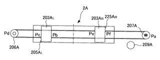
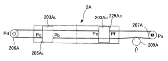
(1)まず、図8に示すように張力付与ロール209Aをワイヤ205ARから離反させる。これにより、駆動ローラ207Aと左マスキングユニット203ALとの間(図8では、点Paと点Pbとの間)で右ワイヤ205ARの張力TRUがゼロ(TRU=0)になる。
張力付与ロール209Aを右ワイヤ205ARから離反させたら、モータ208Aによりマスキングユニット203AL,Rが相互に離反するように駆動ローラ207Aを回転させる。
ここで、モータ208Aは駆動ローラ207Aを一定の低トルク2T0で回転させるものとし、左マスキングユニット203ALが左位置決めストッパー225ALに当接する、又は右マスキングユニット203ARが右位置決めストッパー225ARに当接することにより右ワイヤ205ARに一定の張力(ここでは2T0)がかかると、駆動ローラ207Aはそれ以上回転することなく回転を停止する。これを利用して、本実施例では駆動ローラ207Aの回転の停止をモータ208Aのトルク電流等により検出したら、左マスキングユニット203ALが左位置決めストッパー225ALに当接した、又は右マスキングユニット203ARが右位置決めストッパー225ARに当接したと判断する。
(2)駆動ローラ207Aの回転停止を検出したら、続いてロードセル267Aによる測定値TLに基づいてマスキングユニット203AL,Rのうちのどちらが位置決めストッパー225AL,Rに当接したのかを判断する。
具体的には、ロードセル267Aによる測定値TLが2T0よりも小さい(TL<2T0)場合、左ワイヤ205ALに荷重が作用しておらず、図9に示すように,右マスキングユニット203ARの鋼板板幅方向Yの中心からの距離が左マスキングユニット203ALの鋼板板幅方向Yの中心からの距離よりも長く、左マスキングユニット203ALが左位置決めストッパー225ALに当接するよりも先に右マスキングユニット203ARが右位置決めストッパー225ARに当接したと判断して後述する(3)の処理に移行する。
ここで、右マスキングユニット203ARが先に右位置決めストッパー225ARに当接し駆動ローラ207Aが回転を停止した状態において、駆動ローラ207Aと右マスキングユニット203ARとの間(図9では点Paと点Pfとの間)で右ワイヤ205ARの張力TRLは2T0(TRL=2T0)となる。また、駆動ローラ207Aと左マスキングユニット203ALとの間の右ワイヤ205ARの張力TRU、支持ローラ206Aと左マスキングユニット203ALとの間(図9では点Pdと点Pcとの間)の左ワイヤ205ALの張力TLU、支持ローラ206Aと右マスキングユニット203ARとの間(図9では点Pdと点Peとの間)の左ワイヤ205ALの張力TLLはそれぞれゼロ(TRU=0,TLU=0,TLL=0)となる。
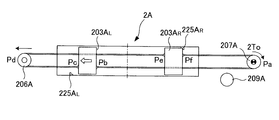
一方、ロードセル267Aによる測定値TLが2T0よりも大きい(TL>2T0)である場合、左ワイヤ205ALに作用している荷重が駆動ローラ207Aのトルクと同じ値であり、図10に示すように,左マスキングユニット203ALの鋼板板幅方向Yの中心からの距離が右マスキングユニット203ARの鋼板板幅方向Yの中心からの距離よりも長く、右マスキングユニット203ARが右位置決めストッパー225ARに当接するよりも先に左マスキングユニット203ALが左位置決めストッパー225ALに当接したと判断して後述する(3’)の処理に移行する。
ここで、左マスキングユニット203ALが先に左位置決めストッパー225ALに当接し駆動ローラ207Aが回転を停止した状態において、駆動ローラ207Aと右マスキングユニット203ARとの間(図10では点Paと点Pfとの間)で右ワイヤ205ARの張力TRLは2T0(TRL=0)となる。また、駆動ローラ207Aと左マスキングユニット203ALとの間の右ワイヤ205ARの張力TRUはゼロ(TRU=0)のままとなり、支持ローラ206Aと左マスキングユニット203ALとの間(図10では点Pdと点Pcとの間)の左ワイヤ205ALの張力TLU、支持ローラ206Aと右マスキングユニット203ARとの間(図10では点Pdと点Peとの間)の左ワイヤ205ALの張力TLLは2T0(TLU=2T0,TLL=2T0)となる。また、ロードセル267Aによる測定値TLは4T0(TL=4T0)となる。
なお、上述した(2)の処理においてロードセル267Aによる測定値TLが(TL=2T0)2T0であった場合はマスキングユニット203AL,Rがそれぞれ位置決めストッパー225AL,Rに当接していると判断することができる。
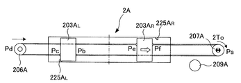
(3)上述した(2)の処理において右マスキングユニット203ARが右位置決めストッパー225ARに当接したと判断したら、続いて、左マスキングユニット203ALを左位置決めストッパー225ALに当接する位置まで移動させるため、スクリューシャフト266Aを回転させてスライドベース262A、ローラホルダ263Aを介して支持ローラ206Aをスプレーヘッダー2から離反する方向へ移動させる(図9参照)。これにより、左マスキングユニット203ALが右マスキングユニット203ARから離反する方向へ移動する。
その後、図11に示すように左マスキングユニット203ALが左位置決めストッパー225ALに当接し、且つロードセル267Aによる測定値TLが駆動ローラ207Aのトルクの半分の値(TL=2T0)となるまで支持ローラ206Aを移動させたらスクリューシャフト266Aの回転を止め、スライドベース262Aの位置を固定するために図2(b)に示すように凸部262Acと突出部263Acとの間に取外し式の位置決め用スペーサ268Aを取り付ける。
(3’)また、上述した(2)の処理において左マスキングユニット203ALが左位置決めストッパー225ALに当接したと判断したら、続いて、右マスキングユニット203ARを右位置決めストッパー225ARに当接する位置まで移動させるため、スクリューシャフト266Aを回転させてスライドベース262Aをスプレーヘッダー2に近接する方向へ移動させる(図10参照)。これにより、右マスキングユニット203ARが左マスキングユニット203ALから離反する方向へ移動する。
その後、図11に示すように右マスキングユニット203ARが右位置決めストッパー225ARに当接し、且つロードセル267Aによる測定値TLが駆動ローラ207Aのトルクの半分の値(TL=2T0)となるまで支持ローラ206Aを移動させたらスクリューシャフト266Aの回転を止め、スライドベース262Aの位置を固定するために図2(b)に示すように凸部262Acと突出部263Acとの間に取外し式の位置決め用スペーサ268Aを取り付ける。
ここで、上述した(3)または(3’)の処理により図11に示すようにマスキングユニット203AL,Rがそれぞれ位置決めストッパー225AL,Rに当接すると、張力TRU,TLU,TLL,TRLはそれぞれTRU=0,TLU=T0,TLL=T0,TRL=2T0となる。
(4)マスキングユニット203AR,Lがそれぞれ位置決めストッパー225AR,Lに当接し、且つロードセル267Aによる測定値TLが駆動ローラ207Aのトルクの半分の値(TL=2T0)となったら、最後に図12に示すように張力付与ロール209Aを右ワイヤ205ARに押し当てて、駆動ローラ207Aと左マスキングユニット203ALとの間で右ワイヤ205ARに張力TRU=T0を付与する。これにより、張力TRU,TLU,TLL,TRLはそれぞれT0(TRU=TLU=TLL=TRL=T0)となってワイヤ205AL,Rの張力が相互に釣り合った状態となり、ゼロ点調整が完了する。
上述した熱延鋼板の冷却装置のマスク部材位置調整方法によれば、マスキングユニット203AL,Rが上スプレーヘッダー2Aに内蔵されて該マスキングユニット203AL,Rの位置を目視で確認することができなくても、高精度にマスキングユニット203AL,Rのゼロ点調整を行うことができる。
なお、上述したゼロ点調整は、例えばメンテナンスのために上スプレーヘッダー2Aの分解を行った後など、必要に応じて行うものとする。
なお、上述したゼロ点調整は、例えばメンテナンスのために上スプレーヘッダー2Aの分解を行った後など、必要に応じて行うものとする。
次に、本実施例に係る熱延鋼板の冷却装置による作用効果について説明する。熱延鋼板の冷却は、ゼロ点調整によりマスキングユニット203AR,Lの位置を調整した状態で行う。
例えば、熱延鋼板1の鋼板板幅方向Yに対し、例えば熱延鋼板1の板端部の過冷却を低減したい場合、スプレー不使用時において、モータ208Aを駆動して駆動ローラ207Aを回転させマスキングユニット203AL,Rを熱延鋼板1の板端部に対向する位置へと移動させる。
他方、熱延鋼板1の鋼板板幅方向Yの中央部の過冷却を低減したい場合、スプレー不使用時において、モータ208Aを駆動して駆動ローラ207Aを回転させマスキングユニット203AL,Rを熱延鋼板1の鋼板板幅方向Yの中央部に対向する位置へと移動させる。
他方、熱延鋼板1の鋼板板幅方向Yの中央部の過冷却を低減したい場合、スプレー不使用時において、モータ208Aを駆動して駆動ローラ207Aを回転させマスキングユニット203AL,Rを熱延鋼板1の鋼板板幅方向Yの中央部に対向する位置へと移動させる。
このとき、遮蔽板232A及び平面シール238Aは弾性体235Aの弾性力によりスプレー板201Aとは離間しているため、マスキングユニット203AL,Rの移動の際にスプレー板201Aと接触することがなく、遮蔽板232A及び平面シール238Aの劣化を抑制して長寿命化を図ることが可能となる。
また、このときワイヤ205Aを覆う被覆シール281Aがワイヤシール282Aに摺接することとなるが、被覆シール281Aとワイヤシール282Aとの接触は線接触であるため、被覆シール281A及びワイヤシール282Aが摩擦により劣化することを抑制することができ、被覆シール281A及びワイヤシール282Aの長寿命化を図ることが可能となる。
また、このときワイヤ205Aを覆う被覆シール281Aがワイヤシール282Aに摺接することとなるが、被覆シール281Aとワイヤシール282Aとの接触は線接触であるため、被覆シール281A及びワイヤシール282Aが摩擦により劣化することを抑制することができ、被覆シール281A及びワイヤシール282Aの長寿命化を図ることが可能となる。
そして、マスキングユニット203AL,Rを所望の位置に移動させたら、冷却水供給管3Aを介して図示しない冷却水供給減から高圧の冷却水をスプレーヘッダー本体部202A内へ供給する。
このとき、水圧により平面シール238Aが遮蔽板232Aとともに弾性体235Aの弾性力に反してスプレー板201A側へ移動するとともに、平面シール238Aの自由端がスプレー板201Aに押し当てられて平面シール238Aにより囲まれた範囲にある冷却水噴射孔211Aへの冷却水の供給が遮断される。
また、同時にワイヤシール282Aのテーパ部が水圧により鋼板板幅方向Yの外側へと撓んで被覆シール281Aに押し当てられ、被覆シール281Aとワイヤシール282Aとの接触圧により、スプレーヘッダー2Aの内部から外部へ冷却水が漏出することを抑制する。
このとき、水圧により平面シール238Aが遮蔽板232Aとともに弾性体235Aの弾性力に反してスプレー板201A側へ移動するとともに、平面シール238Aの自由端がスプレー板201Aに押し当てられて平面シール238Aにより囲まれた範囲にある冷却水噴射孔211Aへの冷却水の供給が遮断される。
また、同時にワイヤシール282Aのテーパ部が水圧により鋼板板幅方向Yの外側へと撓んで被覆シール281Aに押し当てられ、被覆シール281Aとワイヤシール282Aとの接触圧により、スプレーヘッダー2Aの内部から外部へ冷却水が漏出することを抑制する。
これにより、熱延鋼板1の板端部の過冷却を低減したい場合には図1(a)に示すように冷却水を熱延鋼板1の板中央部に噴射する一方、熱延鋼板1の板端部に冷却水が噴射されることを防止することができ、板端部の過冷却を低減して熱延鋼板1の幅方向の温度分布を均一化することが可能となる。
また、熱延鋼板1の鋼板板幅方向Yの中央部の過冷却を低減したい場合には図1(b)に示すように冷却水を熱延鋼板1の板端部側に噴射する一方、熱延鋼板1の板中央部に冷却水が噴射されることを防止することができ、板中央部の過冷却を低減して熱延鋼板1の幅方向の温度分布を均一化することが可能となる。
また、熱延鋼板1の鋼板板幅方向Yの中央部の過冷却を低減したい場合には図1(b)に示すように冷却水を熱延鋼板1の板端部側に噴射する一方、熱延鋼板1の板中央部に冷却水が噴射されることを防止することができ、板中央部の過冷却を低減して熱延鋼板1の幅方向の温度分布を均一化することが可能となる。
さらに、このときマスキングユニット203AL,Rはスプレーヘッダー2Aの内部において冷却水により冷却されている状態となるため、熱延鋼板1の熱により熱変形するおそれがない。さらに加えて、スプレーヘッダー201Aの内部においてスプレー板201Aの冷却水噴射孔211Aをマスキングユニット203AL,Rによって直接閉塞することができるため、スプレーヘッダー2A内の冷却水をマスキングユニット203AL,Rによって覆われた領域以外にある冷却水噴射孔211Aから均等に熱延鋼板1に向けて噴射させることができるため、熱延鋼板1の幅方向両端で板上水が効率的に流れて該板上水の排水経路を安定化させることができる。
なお、本実施例では、一つのスプレーヘッダー2Aに、それぞれ二つのマスキングユニット203AL,Rを設ける例を示したが、一つのスプレーヘッダー2Aに設けるマスキングユニットの個数は二つに限らず、一つまたは三つ以上であってもよく、例えばスライド式に鋼板板幅方向Yの長さを変更できるような構成としてもよい。
また、本実施例では、右ワイヤ205ARを駆動ローラ207Aに半周以上巻き付けることによって当該右ワイヤ205ARが駆動ローラ207Aに対してすべりが生じないように構成したが、右ワイヤ205ARに張力が作用しない状態でも当該右ワイヤ205ARを駆動ローラ207Aに押し付けることができる構造であれば、他の方法を用いてもよい。
また、本実施例では、第一の移動手段として支持ローラ206A、駆動ローラ207A、ワイヤ205A及び被覆シール281Aを用いる例を示したが、ワイヤ205Aに代えてロープを用いてもよい。
また、本実施例では、荷重検出手段としてロードセル267Aを用いる例を示したが、図13に示すようにロードセル267Aに代えてばね269Aを用いてもよく、本発明の趣旨を逸脱しない範囲で種々の変更が可能である。
また、上スプレーヘッダー2Aと下スプレーヘッダー2Bとは、下スプレーヘッダー2Bのマスキングユニット203BL,203BRが、上スプレーヘッダー2Aのマスキングユニット203AL,Rに対し、凹溝を形成し弾性体を載置する位置をホルダ部の遮蔽板に対向する面上とする点で異なるのみであるので、下スプレーヘッダー2Bについての詳しい説明は省略する。
下スプレーヘッダー2Bにマスキングユニット203BL,203BRを適用した場合も、上スプレーヘッダー2Aによる熱延鋼板1の上面の冷却と同様、熱延鋼板1の下面の冷却に関して、熱延鋼板1の幅方向両端部で板上水の流れを妨げる下からの冷却水の噴射を遮断することができ、板上水の排水経路を安定化させるとともに所望の部分の過冷却を低減することができ、装置の大型化を抑制しつつ鋼板板幅方向Yの温度分布を均一化することが可能となる。
下スプレーヘッダー2Bにマスキングユニット203BL,203BRを適用した場合も、上スプレーヘッダー2Aによる熱延鋼板1の上面の冷却と同様、熱延鋼板1の下面の冷却に関して、熱延鋼板1の幅方向両端部で板上水の流れを妨げる下からの冷却水の噴射を遮断することができ、板上水の排水経路を安定化させるとともに所望の部分の過冷却を低減することができ、装置の大型化を抑制しつつ鋼板板幅方向Yの温度分布を均一化することが可能となる。
このように、本発明の実施例1に係る熱延鋼板の冷却装置及びそのマスク部材位置調整方法によれば、装置の大型化を抑制するとともにマスキングユニット203AL,R,203BL,Rの長寿命化を図りつつ、熱延鋼板の幅方向の温度分布を均一化することが可能となり、また、マスキングユニット203AL,R,203BL,Rがスプレーヘッダー2A,2Bに内蔵された状態であってもマスキングユニット203AL,Rの位置調整を高精度に行うことが可能となる。
図14に基づいて本発明の実施例2に係る熱延鋼板の冷却装置の詳細を説明する。
本実施例に係る熱延鋼板の冷却装置は、図1から図13に示し上述した実施例1に係る熱延鋼板の冷却装置のマスキングユニット203AL,Rに代えて、図14に示すマスキングユニット503AL,503ARを用いる例である。その他の構成は実施例1と同様であり、以下、同一の作用を奏する部材には同一の符号を付して重複する説明は省略し、異なる点を中心に説明する。
本実施例に係る熱延鋼板の冷却装置は、図1から図13に示し上述した実施例1に係る熱延鋼板の冷却装置のマスキングユニット203AL,Rに代えて、図14に示すマスキングユニット503AL,503ARを用いる例である。その他の構成は実施例1と同様であり、以下、同一の作用を奏する部材には同一の符号を付して重複する説明は省略し、異なる点を中心に説明する。
図14(a)に示すように、本実施例においてマスキングユニット503AL,503ARは、鋼板板幅方向Yの長さが、鋼板搬送方向Xに沿って変化している。具体的には、マスキングユニット503AL,503ARは、鋼板搬送方向Xの上流側から鋼板搬送方向Xの下流側に向かうにしたがって相互の距離が狭くなるように上面視概ね台形状に形成されている。
本実施例に係る熱延鋼板の冷却装置によれば、図14(b)に示すように、鋼板搬送方向Xの上流側においては冷却水の流量を多く、鋼板搬送方向Xの下流側においては冷却水の流量を少なくすることができ、上述した実施例1の効果に加えて、鋼板板幅方向Yの冷却能力の制御性をより向上させることが可能となる。これは、下スプレーヘッダー2Bに適用した場合も同様である。
図15に基づいて本発明の実施例3に係る熱延鋼板の冷却装置の詳細を説明する。
本実施例に係る熱延鋼板の冷却装置は、図1から図13に示し上述した実施例1に係る熱延鋼板の冷却装置の平面シール238Aに代えて、図15に示すマスキングシート630Aを用いる例である。その他の構成は実施例1と同様であり、以下、同一の作用を奏する部材には同一の符号を付して重複する説明は省略し、異なる点を中心に説明する。
本実施例に係る熱延鋼板の冷却装置は、図1から図13に示し上述した実施例1に係る熱延鋼板の冷却装置の平面シール238Aに代えて、図15に示すマスキングシート630Aを用いる例である。その他の構成は実施例1と同様であり、以下、同一の作用を奏する部材には同一の符号を付して重複する説明は省略し、異なる点を中心に説明する。
図15(a)に示すように、マスキングシート630Aは、シート状に形成されてマスキングユニット203AL,Rから該マスキングユニット203AL,Rの鋼板板幅方向Yの外側の全域にわたって冷却水噴射孔211Aを覆うものであり、巻取機701Aによって巻取できるようになっている。なお、図15(a)中の符号702Aはマスキングシート630Aを巻取機701Aへ案内するローラである。
このマスキングシート630Aは、図15(b)に示すように、例えば鉄を薄い板状に形成した板体361Aを、弾性体からなる被覆シール632Aにより被覆してなり、スプレーヘッダー本体部202Aに形成された貫通孔224Aに摺動自在に挿通されている。貫通孔224Aは、鋼板板幅方向Yの内側が外部側よりも大径に形成されて、この大径部に例えばテフロンからなる筒状の平面シール633Aが嵌入されている。平面シール633Aは該平面シール633Aの鋼板板幅方向Yの内側の面の外周側を覆う環状のカバー板634Aによって固定されている。カバー板634Aは固定ボルト209Aによってスプレーヘッダー本体部202Aに固定されている。
平面シール633Aは、鋼板板幅方向Yの内側の内径が被覆シール632Aの外径と概ね同一であるとともに被覆シール632Aに対向する面が断面視円弧状に形成されている。さらに、鋼板板幅方向Yの外側に向かうにしたがって内径が広くなるテーパ部を有している。これにより、被覆シール632Aと平面シール633Aとは、図7に示し上述したワイヤシール282Aと同様に、スプレー不使用時においては線接触(断面でみると点接触)となる一方、スプレー使用時においては平面シール633Aのテーパ部が水圧により鋼板板幅方向Yの外側に向かって撓み、被覆シール632Aに押し当てられることとなる。
つまり、平面シール633Aは、スプレー不使用時においては被覆シール632Aとの接触状態が断面視点接触となり、マスキングユニット203AL,Rを移動させる際に被覆シール632Aとの摩擦を最小限に抑えることができる一方、スプレー使用時においては被覆シール632Aに押し当てられることにより冷却水が貫通孔223Aから漏出することを抑制することができるのである。
以上に説明した本実施例に係る熱延鋼板の冷却装置では、マスキングシート630Aにより遮蔽体を構成し、平面シール633Aにより第一のシール部材を構成している。
このように構成される本実施例に係る熱延鋼板の冷却装置によれば、上述した実施例1に係る熱延鋼板の冷却装置による作用効果に加えて、例えば板幅の狭い熱延鋼板1の冷却を行う場合に熱延鋼板1のエッジの位置に合わせてマスキングユニット203AL,Rを移動させた際、マスキングユニット203AL,Rよりも鋼板板幅方向Yの外側に冷却水噴射孔211Aがあっても、マスキングシート630Aによってマスキングユニット203AL,Rよりも鋼板板幅方向Yの外側にある冷却水噴射孔211を塞ぐことができるため、冷却水を節約することができる。さらにこのとき、冷却水供給管3Aを介して図示しない冷却水供給減から高圧の冷却水をスプレーヘッダー本体部202A内へ供給すると、平面シール633Aのテーパ部が水圧により鋼板板幅方向Yの外側へと撓んで被覆シール632Aに押し当てられ、被覆シール632Aと平面シール633Aとの接触圧により、上スプレーヘッダー2Aの内部から外部へ冷却水が漏出することを抑制することができる。これは、下スプレーヘッダー2Bに適用した場合も同様である。
なお、本実施例では、カバー板283Aとカバー板634Aとを別体とする例を示したが、図16に示すように、マスキングシート630Aを摺動自在に挿通するスプレーヘッダー本体部202Aに形成された貫通孔224Aを、ワイヤ205Aを摺動自在に挿通するスプレーヘッダー本体部202Aに形成された貫通孔223Aの近傍に形成し、ワイヤシール282Aと平面シール633Aとを一つのカバー板635Aにより固定するようにしてもよい。なお、図16(a)に示す符号603ARはマスキングユニット、符号703Aはマスキングシート630Aを貫通孔へ案内するための案内ブロックである。
本発明は、熱延鋼板の冷却装置及びそのマスク部材位置調整方法に適用して好適なものである。
1 熱延鋼板
2,2A,2B スプレーヘッダー
201A スプレー板
202A スプレーヘッダー本体部
203AL,203AR,503AL,503AR マスキングユニット
205AL,205AR ワイヤ
206A 駆動ローラ
207A 支持ローラ
208A モータ
211A 冷却水噴射孔
222AU,203AL ガイドレール
225AL,225AR 位置決めストッパー
231A ホルダ部
232A 遮蔽板
235A 弾性体
238A 平面シール
262A スライドベース
266A スクリューシャフト
267A ロードセル
282A ワイヤシール
630A マスキングシート
632A 被覆シール
633A 平面シール
2,2A,2B スプレーヘッダー
201A スプレー板
202A スプレーヘッダー本体部
203AL,203AR,503AL,503AR マスキングユニット
205AL,205AR ワイヤ
206A 駆動ローラ
207A 支持ローラ
208A モータ
211A 冷却水噴射孔
222AU,203AL ガイドレール
225AL,225AR 位置決めストッパー
231A ホルダ部
232A 遮蔽板
235A 弾性体
238A 平面シール
262A スライドベース
266A スクリューシャフト
267A ロードセル
282A ワイヤシール
630A マスキングシート
632A 被覆シール
633A 平面シール
Claims (10)
- 搬送方向に移動する熱延鋼板の上下に多数の冷却水噴射孔を有するスプレー板と当該スプレー板を覆う箱状の本体部とを具備するスプレーヘッダーを対向配置し、前記冷却水噴射孔から前記熱延鋼板に冷却水を吹き付けることによって前記熱延鋼板の冷却を行う熱延鋼板の冷却装置において、
前記スプレーヘッダーが、前記本体部の内周面に設けられ前記熱延鋼板の板幅方向に沿って延びる案内レールと、前記案内レールに沿って移動するマスク部材とを内蔵し、
前記マスク部材が、前記案内レールに沿って前記熱延鋼板の板幅方向に移動可能に設けられた支持体と、少なくとも上下方向に弾性変形可能な弾性体を介して前記支持体に支持される遮蔽体とを有し、
前記遮蔽体が、水圧が作用していないときは前記スプレー板から離反し、水圧が作用しているときは前記弾性体が圧縮変形されることにより前記スプレー板に押圧されて所望の前記冷却水噴射孔を塞ぐ
ことを特徴とする熱延鋼板の冷却装置。 - 前記遮蔽体は、板状に形成されて前記スプレー板に対向する遮蔽板と、断面視概ねV字状に形成され解放部が外側を向くように前記遮蔽板の外周縁に固着された平面シールとからなる
ことを特徴とする請求項1に記載の熱延鋼板の冷却装置。 - 前記遮蔽体は、金属からなる薄板と、該薄板を被覆する弾性体とからなり、前記スプレーヘッダーの外側で巻取可能に構成されて前記マスク部材の直下から前記熱延鋼板の板幅方向外側にある全ての前記冷却水噴射孔を覆うマスキングシートであり、
前記マスキングシートは、前記スプレーヘッダーに形成された貫通孔に、環状に形成された第一のシール部材を介して挿通され、
前記第一のシール部材は、水圧が作用していないときは前記薄板を被覆する弾性体に線接触する一方、水圧が作用しているときは前記薄板を被覆する弾性体を押圧する
ことを特徴とする請求項1に記載の熱延鋼板の冷却装置。 - 前記遮蔽体の形状は、水量分布を幅方向に勾配をもって変化させるように、前記熱延鋼板の板幅方向に沿った長さが前記熱延鋼板の搬送方向に沿って変化する
ことを特徴とする請求項1から請求項3のいずれか1項に記載の熱延鋼板の冷却装置。 - 前記スプレーヘッダーの外部に駆動源を有し、前記マスク部材を前記熱延鋼板の板幅方向に移動させる第一の移動手段を備える
ことを特徴とする請求項1から請求項4のいずれか1項に記載の熱延鋼板の冷却装置。 - 前記第一の移動手段は、前記スプレーヘッダーの外側であり前記熱延鋼板の板幅方向の両側に各々設置された駆動ローラ及び非駆動ローラと、前記駆動ローラ及び非駆動ローラに巻きかけられて両端が前記マスク部材に固定されたワイヤとから構成され、
前記ワイヤは、弾性体により被覆され、前記スプレーヘッダーに形成された貫通孔に、環状に形成された第二のシール部材を介して挿通され、
前記第二のシール部材は、水圧が作用していないときは前記ワイヤを被覆する弾性体に線接触する一方、水圧が作用しているときは前記ワイヤを被覆する弾性体を押圧して該弾性体に密着する
ことを特徴とする請求項5に記載の熱延鋼板の冷却装置。 - 前記スプレーヘッダーは、前記熱延鋼板の板幅中央部を挟んで対称に配置される複数の前記マスク部材を内蔵し、
前記第一の移動手段は、前記熱延鋼板の板幅方向の中央部を挟んで対向する前記マスク部材を、相互に連動して接近離反移動させる
ことを特徴とする請求項5又は請求項6に記載の熱延鋼板の冷却装置。 - 前記第二のシール部材は、高剛性体からなり、水圧作用とは関係なくワイヤを被覆する弾性体に一定の押圧を与え密着するとともに、使用する水圧の大きさによって選択される
ことを特徴とする請求項6又は請求項7に記載の熱延鋼板の冷却装置。 - 前記マスク部材の前記熱延鋼板の板幅方向の移動を規制するストッパーと、
前記マスク部材が前記ストッパーに当接したことを検出する当接検出手段と、
前記非駆動ローラに巻きかけられたワイヤに作用する荷重を測定する荷重測定手段と、
前記非駆動ローラを前記熱延鋼板の板幅方向に移動させる第二の移動手段とを備える
ことを特徴とする請求項7又は請求項8に記載の熱延鋼板の冷却装置。 - 請求項9に記載の熱延鋼板の冷却装置において、
前記駆動ローラを回転させて前記熱延鋼板の板幅方向の中央部を挟んで対向する前記マスク部材を相互に離反する方向へ移動させ、
前記当接検出手段により少なくとも一方の前記マスク部材が前記ストッパーに当接したことを検出したら前記荷重測定手段による測定値が予め設定する値となるまで前記第二の移動手段により前記非駆動ローラを前記熱延鋼板の板幅方向に移動させる
ことを特徴とする熱延鋼板の冷却装置のマスク部材位置調整方法。
Priority Applications (2)
| Application Number | Priority Date | Filing Date | Title |
|---|---|---|---|
| CN201680002424.9A CN106660091B (zh) | 2015-05-26 | 2016-02-19 | 热轧钢板的冷却装置及其掩蔽构件位置调整方法 |
| EP16799612.3A EP3305427B1 (en) | 2015-05-26 | 2016-02-19 | Cooling device for hot rolled steel plate and method for adjusting mask member position therefor |
Applications Claiming Priority (2)
| Application Number | Priority Date | Filing Date | Title |
|---|---|---|---|
| JP2015-106080 | 2015-05-26 | ||
| JP2015106080A JP6245766B2 (ja) | 2015-05-26 | 2015-05-26 | 熱延鋼板の冷却装置及びそのマスク部材位置調整方法 |
Publications (1)
| Publication Number | Publication Date |
|---|---|
| WO2016189903A1 true WO2016189903A1 (ja) | 2016-12-01 |
Family
ID=57393046
Family Applications (1)
| Application Number | Title | Priority Date | Filing Date |
|---|---|---|---|
| PCT/JP2016/054779 Ceased WO2016189903A1 (ja) | 2015-05-26 | 2016-02-19 | 熱延鋼板の冷却装置及びそのマスク部材位置調整方法 |
Country Status (4)
| Country | Link |
|---|---|
| EP (1) | EP3305427B1 (ja) |
| JP (1) | JP6245766B2 (ja) |
| CN (1) | CN106660091B (ja) |
| WO (1) | WO2016189903A1 (ja) |
Cited By (1)
| Publication number | Priority date | Publication date | Assignee | Title |
|---|---|---|---|---|
| WO2019197182A1 (de) | 2018-04-13 | 2019-10-17 | Sms Group Gmbh | Kühleinrichtung zum kühlen eines metallischen gutes sowie verfahren zu deren herstellung und betrieb |
Families Citing this family (4)
| Publication number | Priority date | Publication date | Assignee | Title |
|---|---|---|---|---|
| CN108177155B (zh) * | 2018-03-21 | 2024-06-07 | 北京延锋北汽汽车内饰件有限公司 | 一种仪表板火焰处理抓手装置 |
| CN109550784B (zh) * | 2018-11-12 | 2019-11-12 | 中国兵器科学研究院宁波分院 | 一种用于泡沫铝三明治板的热轧设备 |
| CN111004911A (zh) * | 2019-12-31 | 2020-04-14 | 北京星和众工设备技术股份有限公司 | 一种彩涂板冷却系统 |
| KR102792359B1 (ko) * | 2022-06-23 | 2025-04-08 | 현대제철 주식회사 | 스크류 보호 커버 및 이를 구비한 에지마스크 장치 |
Citations (2)
| Publication number | Priority date | Publication date | Assignee | Title |
|---|---|---|---|---|
| JPH06285531A (ja) * | 1993-03-31 | 1994-10-11 | Nippon Steel Corp | 熱鋼板の冷却装置 |
| JP2007319928A (ja) * | 2006-06-05 | 2007-12-13 | Kobe Steel Ltd | マスキング装置 |
Family Cites Families (6)
| Publication number | Priority date | Publication date | Assignee | Title |
|---|---|---|---|---|
| JPS5916711U (ja) * | 1982-07-21 | 1984-02-01 | 住友金属工業株式会社 | 鋼板の冷却装置 |
| JPH081231A (ja) * | 1994-06-16 | 1996-01-09 | Nippon Steel Corp | 熱板冷却装置 |
| JP4678112B2 (ja) * | 2001-09-21 | 2011-04-27 | Jfeスチール株式会社 | 鋼板の冷却方法および装置 |
| JP4678069B1 (ja) * | 2009-03-30 | 2011-04-27 | Jfeスチール株式会社 | 熱延鋼板の冷却装置 |
| WO2011074632A1 (ja) * | 2009-12-16 | 2011-06-23 | 新日本製鐵株式会社 | 熱延鋼板の冷却方法 |
| CN203343189U (zh) * | 2013-07-23 | 2013-12-18 | 中冶赛迪工程技术股份有限公司 | 热轧钢板冷却装置 |
-
2015
- 2015-05-26 JP JP2015106080A patent/JP6245766B2/ja active Active
-
2016
- 2016-02-19 CN CN201680002424.9A patent/CN106660091B/zh active Active
- 2016-02-19 WO PCT/JP2016/054779 patent/WO2016189903A1/ja not_active Ceased
- 2016-02-19 EP EP16799612.3A patent/EP3305427B1/en active Active
Patent Citations (2)
| Publication number | Priority date | Publication date | Assignee | Title |
|---|---|---|---|---|
| JPH06285531A (ja) * | 1993-03-31 | 1994-10-11 | Nippon Steel Corp | 熱鋼板の冷却装置 |
| JP2007319928A (ja) * | 2006-06-05 | 2007-12-13 | Kobe Steel Ltd | マスキング装置 |
Cited By (3)
| Publication number | Priority date | Publication date | Assignee | Title |
|---|---|---|---|---|
| WO2019197182A1 (de) | 2018-04-13 | 2019-10-17 | Sms Group Gmbh | Kühleinrichtung zum kühlen eines metallischen gutes sowie verfahren zu deren herstellung und betrieb |
| DE102018211177A1 (de) | 2018-04-13 | 2019-10-17 | Sms Group Gmbh | Kühleinrichtung zum Kühlen eines metallischen Gutes sowie Verfahren zu deren Herstellung und Betrieb |
| US11446720B2 (en) | 2018-04-13 | 2022-09-20 | Sms Group Gmbh | Cooling apparatus for cooling a metallic material and method for cooling a metallic material |
Also Published As
| Publication number | Publication date |
|---|---|
| JP6245766B2 (ja) | 2017-12-13 |
| EP3305427B1 (en) | 2020-04-29 |
| JP2016215261A (ja) | 2016-12-22 |
| CN106660091A (zh) | 2017-05-10 |
| CN106660091B (zh) | 2019-07-09 |
| EP3305427A4 (en) | 2019-01-23 |
| EP3305427A1 (en) | 2018-04-11 |
Similar Documents
| Publication | Publication Date | Title |
|---|---|---|
| JP6245766B2 (ja) | 熱延鋼板の冷却装置及びそのマスク部材位置調整方法 | |
| US10944095B2 (en) | Roll-press apparatus | |
| TW503306B (en) | Strip flatness measuring device | |
| JPWO2013038837A1 (ja) | ローラレベラおよびそれを用いた板材の矯正方法 | |
| JP6269608B2 (ja) | H形鋼フランジ直角度矯正装置 | |
| CN104640650A (zh) | 用于在连铸设备中的铸坯引导的导辊以及辊子组件 | |
| CN102648063B (zh) | 分切带板的蛇行防止装置 | |
| JP2016069095A (ja) | インクジェット印刷装置及びその斜行補正方法 | |
| CN113573999B (zh) | 用于卷对卷加工的流体流卷材张紧装置 | |
| JP5217719B2 (ja) | 連続鋳造設備におけるロールセグメント装置 | |
| KR101477104B1 (ko) | 압연 코일용 권취 장치 | |
| KR101639920B1 (ko) | 방향성 전기강판의 자구미세화 장치 및 그 방법 | |
| KR101569141B1 (ko) | 연속도금설비의 롤장치 | |
| JP7465243B2 (ja) | ステージ装置および電子ビーム描画装置 | |
| WO2016104125A1 (ja) | 搬送ベルトの張力調整方法、搬送装置及びインクジェット記録装置 | |
| RU2346787C2 (ru) | Механизм для направления литейных лент машин для непрерывного литья металлов, оснащенный невращающимся полуцилиндрическим подъемным опорным устройством для ленты | |
| WO2011078385A1 (ja) | スリット帯板の蛇行防止装置 | |
| KR102102939B1 (ko) | 노광 장치, 노광 방법 | |
| JP4794633B2 (ja) | 双ロール式連続薄板キャスティングロールムービング装置 | |
| Masui et al. | Basic examination on strip wandering in processing plants | |
| KR20200064813A (ko) | 위치교정장치 및 이를 포함하는 압연설비 | |
| KR102495678B1 (ko) | 열연강판의 균일 냉각 장치 | |
| JP2020131108A (ja) | 両面塗布装置 | |
| JP2011045893A (ja) | 連続鋳造設備のロールセグメント | |
| JP2003239021A (ja) | 熱処理炉用シール装置 |
Legal Events
| Date | Code | Title | Description |
|---|---|---|---|
| 121 | Ep: the epo has been informed by wipo that ep was designated in this application |
Ref document number: 16799612 Country of ref document: EP Kind code of ref document: A1 |
|
| REEP | Request for entry into the european phase |
Ref document number: 2016799612 Country of ref document: EP |
|
| WWE | Wipo information: entry into national phase |
Ref document number: 2016799612 Country of ref document: EP |
|
| NENP | Non-entry into the national phase |
Ref country code: DE |