WO2016189973A1 - Embrayage électromagnétique pour compresseur de gaz, et compresseur de gaz - Google Patents
Embrayage électromagnétique pour compresseur de gaz, et compresseur de gaz Download PDFInfo
- Publication number
- WO2016189973A1 WO2016189973A1 PCT/JP2016/061145 JP2016061145W WO2016189973A1 WO 2016189973 A1 WO2016189973 A1 WO 2016189973A1 JP 2016061145 W JP2016061145 W JP 2016061145W WO 2016189973 A1 WO2016189973 A1 WO 2016189973A1
- Authority
- WO
- WIPO (PCT)
- Prior art keywords
- electromagnetic clutch
- flange portion
- gas compressor
- armature
- axis
- Prior art date
- Legal status (The legal status is an assumption and is not a legal conclusion. Google has not performed a legal analysis and makes no representation as to the accuracy of the status listed.)
- Ceased
Links
Images







Classifications
-
- F—MECHANICAL ENGINEERING; LIGHTING; HEATING; WEAPONS; BLASTING
- F04—POSITIVE - DISPLACEMENT MACHINES FOR LIQUIDS; PUMPS FOR LIQUIDS OR ELASTIC FLUIDS
- F04B—POSITIVE-DISPLACEMENT MACHINES FOR LIQUIDS; PUMPS
- F04B35/00—Piston pumps specially adapted for elastic fluids and characterised by the driving means to their working members, or by combination with, or adaptation to, specific driving engines or motors, not otherwise provided for
-
- F—MECHANICAL ENGINEERING; LIGHTING; HEATING; WEAPONS; BLASTING
- F16—ENGINEERING ELEMENTS AND UNITS; GENERAL MEASURES FOR PRODUCING AND MAINTAINING EFFECTIVE FUNCTIONING OF MACHINES OR INSTALLATIONS; THERMAL INSULATION IN GENERAL
- F16D—COUPLINGS FOR TRANSMITTING ROTATION; CLUTCHES; BRAKES
- F16D27/00—Magnetically- or electrically- actuated clutches; Control or electric circuits therefor
- F16D27/10—Magnetically- or electrically- actuated clutches; Control or electric circuits therefor with an electromagnet not rotating with a clutching member, i.e. without collecting rings
- F16D27/108—Magnetically- or electrically- actuated clutches; Control or electric circuits therefor with an electromagnet not rotating with a clutching member, i.e. without collecting rings with axially movable clutching members
- F16D27/112—Magnetically- or electrically- actuated clutches; Control or electric circuits therefor with an electromagnet not rotating with a clutching member, i.e. without collecting rings with axially movable clutching members with flat friction surfaces, e.g. discs
Definitions
- the present invention relates to an electromagnetic clutch for a gas compressor and a gas compressor.
- a gas compressor that compresses a gas such as a refrigerant gas into a high-pressure compressed gas is used in an air conditioning system (hereinafter referred to as an air conditioning system).
- an air conditioning system one that operates by receiving power from the outside is provided with an electromagnetic clutch in order to switch connection / disconnection of the power.
- the electromagnetic clutch contacts the outer surface of the rotor by the rotor that rotates integrally with the pulley, the electromagnetic coil, and the magnetic flux generated by energization of the electromagnetic coil, and moves away from the outer surface of the rotor by the disappearance of the magnetic flux by the deenergization of the electromagnetic coil
- An armature and a hub having a flange portion connected to the armature via a leaf spring and a boss portion connected to the rotating shaft are provided. (For example, refer to Patent Document 1).
- Patent Document 1 proposes a technique for providing an elastic material between a leaf spring and a hub. According to this technique, the impact at the time of connection between the armature and the rotor is buffered by the compression of the elastic material to suppress the generation of sound.
- the addition of an elastic material increases the number of parts and the number of assembly steps, leading to an increase in manufacturing cost.
- the inventor of the present invention analyzed in detail the sound generated at the time of connection, and found that the generated sound was deeply related to the natural vibration mode of the hub.
- An object of the present invention is to provide an electromagnetic clutch and a gas compressor for a gas compressor.
- the flange includes: an armature connected to the rotor by a magnetic force; and a hub having a flange connected to the armature via a leaf spring and a boss connected to a rotating shaft.
- the part has a thick part thicker than the thickness of the part outside the boundary at least at a part inside the boundary of the distance set in advance from the axis of the boss part.
- a second aspect of the present invention is a gas compressor including the electromagnetic clutch according to the present invention and a compressor body having a rotating shaft connected to a hub of the electromagnetic clutch.
- FIG. 3 is a cross-sectional view showing a cross section along line BB in FIG. 2.
- FIG. 3 is a perspective view which shows the hub in FIG. It is the graph which showed the vibration sensitivity of the flange part of the electromagnetic clutch of Embodiment 1, and the electromagnetic clutch of the comparative example by which the thick part is not formed in the flange part.
- FIG. 3 shows the armature, leaf
- FIG. 7 is a cross-sectional view showing a cross section along the line CC in FIG. 6. It is a perspective view which shows the hub in FIG. It is a side view which shows the armature, leaf
- FIG. 10 is a cross-sectional view showing a cross section along the line DD in FIG. 9. It is a perspective view which shows the hub in FIG. It is the graph which showed the vibration sensitivity of the flange part of the electromagnetic clutch of Embodiment 3, and the electromagnetic clutch of the comparative example by which the joining rib is not formed in the flange part.
- FIG. 1 is a sectional view showing a longitudinal section of a vane rotary type compressor 100 which is an example of a gas compressor according to the present invention.
- the illustrated compressor 100 is configured as a part of an air conditioning system that performs cooling using, for example, heat of vaporization of a cooling medium. It is provided on the circulation path of the cooling medium together with a condenser, an expansion valve, an evaporator and the like (all of which are not shown) as other components of the air conditioning system.
- this air conditioning system is an air conditioner for adjusting the temperature in the interior of a vehicle (such as an automobile), for example.
- the compressor 100 compresses the refrigerant gas G as a gaseous cooling medium taken from the evaporator, and supplies the compressed refrigerant gas G to the condenser.
- the condenser liquefies the compressed refrigerant gas G and sends it to the expansion valve as a high-pressure liquid refrigerant.
- the high-pressure and liquid refrigerant is reduced in pressure by the expansion valve and sent to the evaporator.
- the low-pressure liquid refrigerant absorbs heat from the surrounding air and vaporizes in the evaporator, and cools the air around the evaporator by removing the heat of vaporization.
- the refrigerant gas G that has been vaporized into gas is returned to the compressor 100.
- the compressor 100 includes a housing 10 formed by a substantially cylindrical main body case 11 having one end opened and the other end closed, and a front head 12 closing the opening on one end side of the main body case 11. have.
- the main body case 11 and the front head 12 are fastened by a plurality of hexagon bolts or the like to form a space inside.
- a compressor body 60 and an oil separator 70 are arranged in the space inside the housing 10.
- An electromagnetic clutch 80 connected to the rotating shaft 51 of the compressor body 60 is fixed to the housing 10 by a retainer (snap ring) 15.
- the electromagnetic clutch 80 is a first embodiment (Embodiment 1) of an electromagnetic clutch for a gas compressor according to the present invention.
- the front head 12 has a suction port 12 a for sucking low-pressure refrigerant gas G from the evaporator into the housing 10.
- the main body case 11 has a discharge port 11a for discharging a high-temperature and high-pressure refrigerant gas G from the inside of the housing 10 to the condenser.
- the front head 12 has a cylindrical nose portion 12b through which the rotating shaft 51 passes, and a flat seat surface 12c against which the electromagnetic clutch 80 is abutted is formed following the nose portion 12b.
- the space inside the housing 10 is partitioned by the compressor body 60 into a suction chamber 13 that communicates with the suction port 12a and a discharge chamber 14 that communicates with the discharge port 11a.
- the compressor main body 60 is, for example, a vane rotary type compressor, and rotates around the axis C of the rotary shaft 51 to suck low-pressure refrigerant gas G through the suction chamber 13 and compress it to high temperature and high pressure.
- the compressed high-pressure refrigerant gas G is discharged into the discharge chamber 14 through the oil separator 70.
- the oil separator 70 separates the refrigerating machine oil R from the refrigerant gas G that passes therethrough.
- the electromagnetic clutch 80 switches connection / disconnection of power supply to the rotating shaft 51.
- the electromagnetic clutch 80 includes a rotor 81, an electromagnetic coil 83, a coil housing 86, an armature 82, and a hub 87.
- the coil housing 86 includes an annular coil case 84 that houses the electromagnetic coil 83 therein, and a flange plate 85 that is joined to the coil case 84 and fixed to the front head 12.
- the flange plate 85 is fixed to the front head by the retainer 15 attached to the nose portion 12b in a state where the surface opposite to the side to which the coil case 84 is joined is abutted against the seat surface 12c formed on the front head 12. 12 is fixed.
- the electromagnetic coil 83 and the coil housing 86 do not move because they are fixed to the housing 10.
- the rotor 81 is formed so as to surround the coil case 84.
- the rotor 81 is coupled to the nose portion 12 b of the front head 12 via a radial ball bearing 17.
- Rotor 81 rotates about axis C integrally with a pulley that receives power from a vehicle on which compressor 100 is mounted.
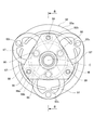
- FIG. 2 is a side view showing the armature 82, the leaf spring 97, and the hub 87 in the electromagnetic clutch 80 of the first embodiment according to the arrow A in FIG. 1
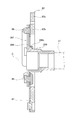
- FIG. 3 is a sectional view taken along the line BB in FIG.
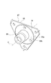
- FIG. 4 is a perspective view showing the hub 87 in FIG.
- the armature 82 is disposed so as to face the end surface (outer surface) of the rotor 81 via a preset gap.
- the armature 82 is substantially circular in a plan view shown in FIG. 2, and has an outer ring portion 82a on the outer side and an inner ring portion 82b on the inner side of the outer ring portion 82a.
- the outer ring portion 82a and the inner ring portion 82b are connected by three connecting portions 82c in the circumferential direction around the axis C.
- the armature 82 is in contact with the end surface of the rotor 81 (see FIG. 1) by the magnetic flux generated by energization of the electromagnetic coil 83, and the rotation of the rotor 81 is transmitted.
- the armature 82 is separated from the end surface of the rotor 81 due to the disappearance of the magnetic flux by the energization stop of the electromagnetic coil 83, and the rotation of the rotor 81 is not transmitted.
- the hub 87 has a cylindrical boss portion 89 centered on the shaft center C, and extends from one end of the boss portion 89 to the outside in the radial direction of the shaft center C. And a flange portion 88.
- the boss portion 89 and the flange portion 88 are integrally formed.
- the boss portion 89 is connected to the rotating shaft 51 by a bolt 16.
- the flange portion 88 has a substantially triangular outline shape in a plan view shown in FIG.
- the flange portion 88 is formed in such a size that the apex that is the longest in the radial direction around the axis C is substantially the same position as the outer shape of the inner ring portion 82 b of the armature 82.
- the flange portion 88 has a portion 88 a (hereinafter referred to as “the outer portion”) that is located on the inner side of the circular boundary M at a predetermined distance from the axis C of the boss portion 89.
- the thick portion 88b is thicker than the thickness of the outer portion 88a.
- the thickness along the axis C of the outer portion 88a is t1
- the thickness along the axis C of the thick portion 88b is t2 (> t1).
- the thick portion 88b is formed in the flange portion 88 over the entire circumference around the axis C.
- the thick part 88 b protrudes in the same direction as the boss part 89 with respect to the flange part 88. Further, the thick part 88 b is formed in contact with the boss part 89.
- the leaf spring 97 is formed in a ring shape. As shown in FIG. 2, three leaf springs 97 are provided in the circumferential direction around the axis C at equal angular intervals. The diameter of the ring of each leaf spring 97 is smaller than the radius of the armature 82. Each leaf spring 97 is coupled to the outer ring portion 82a of the armature 82 by caulking at a portion corresponding to the outer side in the radial direction around the axis C. On the other hand, each leaf spring 97 is coupled and fixed to the flange portion 88 of the hub 87 by a coupling pin 98 at a portion corresponding to the inner side in the radial direction around the axis C.
- the flange portion 88 of the hub 87 is connected to the armature 82 via the leaf spring 97.
- a portion of the flange portion 88 where the leaf spring 97 is fixed by the coupling pin 98 (plate spring fixing portion) is formed in the thick portion 88b. That is, the boundary M is formed on the outer side in the radial direction with respect to the axis C rather than the portion where the leaf spring 97 is fixed.
- the triangular apex of the flange portion 88 is formed in a direction from the axis C toward the portion between the portions where the plate springs 97 are fixed by the coupling pins 98. . That is, each leaf spring 97 is coupled to the flange portion 88 on a line in a direction from the axis C toward the side of the flange portion 88. Therefore, the triangular top portion of the flange portion 88 is on the outer side in the radial direction around the axis C than the portion where the leaf spring 97 is fixed by the coupling pin 98.
- a stopper rubber 99 is fixed to a portion of the outer portion 88a of the flange portion 88 near the top as shown in FIG.
- the stopper rubber 99 is interposed between the flange portion 88 and the inner ring portion 82b of the armature 82 along the axial center C direction, and is in contact with the outer portion 88a of the flange portion 88 and the armature 82. Therefore, the boundary M is formed on the inner side in the radial direction with respect to the axis C than the portion (stopper rubber fixing portion) of the flange portion 88 where the stopper rubber 99 is fixed.
- the armature 82 is attracted to the electromagnetic coil 83 side against the elastic force of the leaf spring 97, whereby the armature 82 contacts the rotor 81 and the rotation of the rotor 81 is caused.
- the rotation transmitted to the armature 82 is transmitted to the rotary shaft 51 via the leaf spring 97 and the hub 87, and the compressor body 60 operates to perform a series of compression operations such as suction, compression and discharge of the refrigerant gas G. .
- the inside of the boundary M is formed into a thick part 88b that is thicker than the thickness of the outer part 88a, and the rigidity of the flange part 88 is formed as the thick part 88b.
- the vibration by the bending of the flange part 88 is suppressed compared with the thing in which the thick part 88b is not formed. Therefore, according to the electromagnetic clutch 80 and the compressor 100 of the present embodiment, it is possible to reduce the level of magnetized sound generated by the vibration of the flange portion 88 without increasing the number of parts such as elastic materials.
- the armature 82 When the electromagnetic coil 83 is not energized, the armature 82 is separated from the rotor 81 by the elastic force of the leaf spring 97, and the operation of the compressor body 60 is stopped. When the armature 82 moves away from the rotor 81, the armature 82 returns to the flange portion 88 side of the hub 87. At this time, since the stopper rubber 99 is interposed between the armature 82 and the flange portion 88, the armature 82 and the flange portion 88 are not in direct contact with each other. Therefore, no sound is generated due to the direct contact between the armature 82 and the flange portion 88.
- FIG. 5 is a graph showing the vibration sensitivity of the flange portion 88 of the electromagnetic clutch 80 of the first embodiment and the electromagnetic clutch of the comparative example in which the thick portion 88b is not formed on the flange portion 88.
- the solid line represents the vibration sensitivity of the electromagnetic clutch 80 of the present embodiment
- the broken line represents the vibration sensitivity of the comparative example.
- the vibration of the flange portion 88 of the electromagnetic clutch 80 of the present embodiment is caused by the displacement of the armature 82 being transmitted through the leaf spring 97 to the portion where the leaf spring 97 is fixed.
- the boundary M of the flange portion 88 is set on the outer side in the radial direction with respect to the axis C rather than the portion where the leaf spring 97 is fixed, so that the leaf spring 97 is fixed.
- the portion becomes the thick portion 88b, and the rigidity of the flange portion 88 is increased.
- a portion fixed to the armature 82 of the flange portion 88 (portion fixed by the coupling pin 98) is formed on the outer side in the radial direction from the boundary portion with the boss portion 89. . Therefore, when the flange portion 88 vibrates due to the displacement of the armature 82, the largest bending stress acts near the boundary portion between the flange portion 88 and the boss portion 89.
- the rigidity of the boundary portion between the flange portion 88 and the boss portion 89 can be further improved.
- the thick portion 88b is formed over the entire circumference around the axis C inside the boundary M formed in a circle. It can be improved over the entire circumference around the axis C.
- the thick portion 88b projects in the same direction with respect to the flange portion 88 in the direction along the boss portion 89 and the axis C, and the leaf spring 97 is fixed to the thick portion 88b. . Accordingly, the gap between the surface of the outer portion 88a facing the armature 82 and the surface of the armature 82 facing the flange portion 88 is wider than that in which the thick portion 88b is not formed.
- the thickness of the stopper rubber 99 sandwiched between the surface of the outer portion 88a facing the armature 82 and the surface of the armature 82 facing the flange portion 88 is reduced. It can be formed thick.
- the flange portion 88 has a substantially triangular outline in plan view in FIG. 2, but the flange portion in the electromagnetic clutch according to the present invention is not limited to this shape, for example, a substantially rectangular shape Or a substantially pentagonal outline. Moreover, the outline shape of the flange part 88 is not limited to a square shape, A circular shape, a star shape, etc. may be sufficient. The same applies to the following embodiments and modifications.
- the leaf spring 97 that couples the armature 82 and the hub 87 is formed in a ring shape.
- the leaf spring in the electromagnetic clutch according to the present invention is not limited to this shape. It may be a shape, a bent shape, or a curved shape. The same applies to the following embodiments and modifications.
- the thick portion 88b is formed over the entire circumference around the axis C, but may be formed only in a part of the range around the axis C. In this case, for example, when formed in a portion in the direction from the axis C toward the top of the flange 88 (the direction toward the portion where the stopper rubber 99 is fixed), the vibration of the top can be effectively suppressed. it can.
- the thick part 88b is formed so as to protrude in the same direction as the boss part 89 with respect to the flange part 88 rather than the outer part 88a.
- the flange portion 88 may be formed so as to protrude in the opposite direction to the boss portion 89.
- the electromagnetic clutch 80 of the present embodiment is formed so that the thick portion 88b is in contact with the boss portion 89, but the electromagnetic clutch according to the present invention is not limited to this form, and the thick portion is separated from the boss portion. It may be formed. In the case where the thick portion is formed away from the boss portion, the thick portion is preferably formed over the entire circumference around the axis of the boss portion.
- FIG. 6 is a side view corresponding to FIG. 2 showing the armature 82, the leaf spring 97, and the hub 187 in the electromagnetic clutch 180 of the second embodiment (Embodiment 2) of the present invention
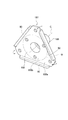
- FIG. FIG. 8 is a perspective view showing the hub 187 in FIG. 6.
- the illustrated electromagnetic clutch 180 is attached to the housing 10 in the compressor 100 shown in FIG. 1 instead of the electromagnetic clutch 80 of the first embodiment.
- the electromagnetic clutch 180 has the same configuration as the electromagnetic clutch 80 except that a hub 187 is provided instead of the hub 87.
- the hub 187 is formed by integrally forming a flange portion 188 corresponding to the flange portion 88 of the hub 87 and a boss portion 189 that is the same as the boss portion 89.
- the flange portion 188 has a thickness direction of the flange portion 188 (along the axis C) from the surface of the flange portion 188 to the outer peripheral edge corresponding to each of the substantially triangular three sides.
- a rib 90 projecting in the direction) is formed.
- the flange portion 188 is the same as the flange portion 88 except that the rib 90 is formed, and the inner side of the boundary M forms a thick portion 188b that is thicker than the outer portion 188a.
- Each rib 90 is formed in a shape extending along the side. As shown in FIG. 7, each rib 90 protrudes in a direction opposite to the boss 189 with respect to the flange 188.
- the leaf spring 97 is formed in a ring shape. As shown in FIG. 6, three leaf springs 97 are provided in the circumferential direction around the axis C at regular angular intervals. The diameter of the ring of each leaf spring 97 is smaller than the radius of the armature 82.
- the triangular top of the flange portion 188 is formed in a direction from the axis C toward the portion between the portions where the leaf springs 97 are fixed by the coupling pins 98. . That is, each leaf spring 97 is coupled to the flange portion 188 on a line in a direction from the axis C toward the side of the flange portion 188. Therefore, the triangular top portion of the flange portion 188 is on the outer side in the radial direction around the axis C than the portion connected to the armature 82 by the connecting pin 98.
- the rotation of the rotor 81 is not transmitted to the armature 82 because the rotor 81 and the armature 82 are separated when the electromagnetic coil 83 is not energized. . Therefore, the rotary shaft 51 connected to the armature 82 via the leaf spring 97 and the hub 187 does not rotate, and the compressor body 60 does not operate.
- the armature 82 is attracted to the electromagnetic coil 83 side against the elastic force of the leaf spring 97, whereby the armature 82 contacts the rotor 81 and the rotation of the rotor 81 is caused.
- the rotation transmitted to the armature 82 is transmitted to the rotary shaft 51 via the leaf spring 97 and the hub 187, and the compressor body 60 operates to perform a series of compression operations such as suction, compression and discharge of the refrigerant gas G. .
- the rib 90 is formed on the outer peripheral edge of the hub 187 together with the thick portion 188b. Therefore, the rigidity of the flange portion 188 is further improved as compared with the flange portion where the thick portion 188b and the rib 90 are not formed. Thereby, the vibration by the bending of the flange part 188 is suppressed compared with the thing without the thick part 188b and the rib 90. FIG. Therefore, according to the electromagnetic clutch 180 and the compressor 100 of the second embodiment, the level of magnetized sound generated by the vibration of the flange portion 188 can be further reduced without increasing the number of parts such as elastic materials.
- the flange portion 188 of the electromagnetic clutch 180 has a triangular apex formed at a portion radially outward from a portion coupled to the armature 82 by the coupling pin 98, so that the flange portion 188 and the boss portion are formed.
- a large bending stress acts near the center of the triangular side.
- the rib 90 is formed corresponding to the triangular side of the flange portion 188 together with the thick portion 188b. Therefore, the rigidity of the side is also increased, and the flange portion 188 is deformed or vibrated. Can be more effectively suppressed.
- the rib 90 corresponding to the side has a linear shape compared to the case where the flange portion 188 is circular (in this case, the rib 90 is arc-shaped), the length of the rib 90 is shorter than that of the arc. can do. Therefore, an increase in weight due to the formed rib 90 can be suppressed.
- the rib 90 protrudes in the direction opposite to the boss portion 89 with respect to the flange portion 188, and therefore the flange portion 188 of the hub 187 with respect to the existing electromagnetic clutch.
- the difference in thickness between the outer portion 188a and the thick portion 188b is the positional relationship between the outer portion 188a and the thick portion 188b. Just change it. Therefore, labor when applying the present invention by design change can be reduced.
- the electromagnetic clutch 180 of the present embodiment has, for example, a flange by bending the outer peripheral portion of the flange portion 188 in which the rib 90 is not formed in the thickness direction of the flange portion 188 (direction along the axis C). Ribs 90 are formed on the outer peripheral edge of the portion 188. Thereby, compared with what joins the rib 90 by welding etc., the rib 90 can be formed easily.
- the electromagnetic clutch according to the present invention is not limited to the electromagnetic clutch in which the rib is formed by this manufacturing method. That is, the rib may be integrally formed by forging when forming the flange portion, or may be formed by being welded to the flange portion.
- the rib 90 is formed so as to protrude in the direction opposite to the boss portion 189 with respect to the flange portion 188, but the rib 90 is formed with respect to the flange portion 188. It may be formed to protrude in the same direction as 189. However, the rib 90 needs to be formed avoiding the leaf spring 97. According to the electromagnetic clutch 180 configured as described above, even if the rib 90 is formed, the entire length of the electromagnetic clutch 180 along the axis C direction can be suppressed to the same length as that of the existing electromagnetic clutch. it can.
- FIG. 9 is a side view corresponding to FIG. 2 showing the armature 82, the leaf spring 97, and the hub 287 in the electromagnetic clutch 280 of the third embodiment (third embodiment) of the present invention
- FIG. 10 is a DD in FIG.
- FIG. 11 is a perspective view showing the hub 287 in FIG. 9.
- the illustrated electromagnetic clutch 280 is attached to the housing 10 in the compressor 100 shown in FIG. 1 instead of the electromagnetic clutch 80 of the first embodiment.
- the electromagnetic clutch 280 has the same configuration as the electromagnetic clutch 80 except that a hub 287 is provided instead of the hub 87 of the electromagnetic clutch 80.
- the hub 287 is formed by integrally forming a flange portion 288 corresponding to the flange portion 88 of the hub 87 and a boss portion 289 that is the same as the boss portion 89.
- the flange portion 288 includes a rib (hereinafter referred to as a joining rib) 288 c that is bridged and joined to the boss portion 89.
- a joining rib hereinafter referred to as a joining rib
- Three joining ribs 288c are formed at equal angular intervals around the axis C.
- the flange portion 288 is formed in a substantially triangular shape having three apexes as in the flange portion 88, and the three joining ribs 288c are on the lines respectively directed from the axis C to the three apexes (as shown in FIG. 11). (Represented by a one-dot chain line).
- Each leaf spring 97 is coupled to the flange portion 288 on a line in a direction from the axis C toward the side of the flange portion 288.
- the three joining ribs 288c are formed in the part between the parts to which the leaf
- the boundary N is an imaginary line with a preset distance from the axis C of the boss portion 89, and the joint portion on the flange portion 288 side of the joining rib 288 c is formed inside the boundary N.
- the rotation of the rotor 81 is not transmitted to the armature 82 because the rotor 81 and the armature 82 are separated when the electromagnetic coil 83 is not energized. . Therefore, the rotary shaft 51 connected to the armature 82 via the leaf spring 97 and the hub 287 does not rotate, and the compressor main body 60 does not operate.
- the armature 82 is attracted to the electromagnetic coil 83 side against the elastic force of the leaf spring 97, whereby the armature 82 contacts the rotor 81 and the rotation of the rotor 81 is caused.
- the rotation transmitted to the armature 82 is transmitted to the rotary shaft 51 via the leaf spring 97 and the hub 287, and the compressor main body 60 operates to perform a series of compression operations such as suction, compression and discharge of the refrigerant gas G. .
- the electromagnetic clutch 280 of the third embodiment is joined with the flange portion 288 and the boss portion 289 being joined.
- 288c increases the rigidity of the flange portion 288 with respect to bending in the thickness direction as compared with the case without the joining rib 288c. Thereby, the vibration by the bending of the flange part 288 is suppressed compared with the thing without the joining rib 288c. Therefore, according to the electromagnetic clutch 280 and the compressor 100 of the third embodiment, the level of magnetized sound generated by the vibration of the flange portion 288 can be further reduced without increasing the number of parts such as elastic materials.
- FIG. 12 is a graph showing the vibration sensitivity of the flange portion 288 of the electromagnetic clutch 280 of the third embodiment and the electromagnetic clutch of the comparative example in which the joining rib 288c is not formed on the flange portion 288.
- the solid line represents the vibration sensitivity of the electromagnetic clutch 280 of the third embodiment
- the broken line represents the vibration sensitivity of the comparative example.
- the joining rib 288c is formed in a portion on a line from the axis C toward the top of the substantially triangular shape of the flange portion 288. Therefore, the electromagnetic clutch 280 can effectively reduce the bending of the triangular portion of the flange portion 288, particularly the top portion.
- the joining rib 288c is formed by the leaf spring 97. It is possible to adopt an arrangement that does not interfere with the portion to be fixed (plate spring fixing portion).
- the compressor 100 of each embodiment mentioned above is a vane rotary type gas compressor
- the gas compressor to which the electromagnetic clutch which concerns on this invention is applied is not limited to a vane rotary type gas compressor. . Therefore, an electromagnetic clutch applied to a gas compressor other than the vane rotary type (swash plate type gas compressor, scroll type gas compressor, etc.) is also an object of the present invention.
Landscapes
- Engineering & Computer Science (AREA)
- General Engineering & Computer Science (AREA)
- Mechanical Engineering (AREA)
- Physics & Mathematics (AREA)
- Electromagnetism (AREA)
- Compressors, Vaccum Pumps And Other Relevant Systems (AREA)
- Compressor (AREA)
Abstract
L'invention concerne un embrayage électromagnétique pour compresseur de gaz dans lequel un bruit de magnétisation est atténué sans augmentation du nombre de composants. Cet embrayage électromagnétique (80) pour un compresseur (100) est équipé : d'une armature (82) connectée et déconnectée vis-à-vis d'un rotor (81) sous l'effet d'une force magnétique ; et d'un moyeu (87) qui possède une partie rebord (88) couplée à l'armature (82) par l'intermédiaire d'un ressort plat (97), et une partie bossage (89) couplée à un axe de rotation (51). La partie rebord (88) du moyeu (87) possède, côté interne d'une interface (M) de distance préétablie depuis le centre axial (C) de la partie bossage (89), une partie épaisse (88b) plus épaisse qu'une portion (partie côté externe (88a)) côté externe de l'interface (M).
Applications Claiming Priority (4)
| Application Number | Priority Date | Filing Date | Title |
|---|---|---|---|
| JP2015104741A JP6570313B2 (ja) | 2015-05-22 | 2015-05-22 | 気体圧縮機用の電磁クラッチ及び気体圧縮機 |
| JP2015-104741 | 2015-05-22 | ||
| JP2015-112842 | 2015-06-03 | ||
| JP2015112842A JP2016223600A (ja) | 2015-06-03 | 2015-06-03 | 気体圧縮機用の電磁クラッチ及び気体圧縮機 |
Publications (1)
| Publication Number | Publication Date |
|---|---|
| WO2016189973A1 true WO2016189973A1 (fr) | 2016-12-01 |
Family
ID=57392683
Family Applications (1)
| Application Number | Title | Priority Date | Filing Date |
|---|---|---|---|
| PCT/JP2016/061145 Ceased WO2016189973A1 (fr) | 2015-05-22 | 2016-04-05 | Embrayage électromagnétique pour compresseur de gaz, et compresseur de gaz |
Country Status (1)
| Country | Link |
|---|---|
| WO (1) | WO2016189973A1 (fr) |
Cited By (2)
| Publication number | Priority date | Publication date | Assignee | Title |
|---|---|---|---|---|
| WO2019105586A3 (fr) * | 2017-11-29 | 2019-09-06 | Eaton Intelligent Power Limited | Embrayage à ressort et système de compresseur d'alimentation |
| CN113459722A (zh) * | 2021-07-07 | 2021-10-01 | 南京航空航天大学 | 可切换运动形态并变换外形的非充气车轮及其变换方法 |
Citations (6)
| Publication number | Priority date | Publication date | Assignee | Title |
|---|---|---|---|---|
| JPS5054753A (fr) * | 1973-09-17 | 1975-05-14 | ||
| JPH0241726U (fr) * | 1988-09-13 | 1990-03-22 | ||
| JPH0271130U (fr) * | 1988-11-21 | 1990-05-30 | ||
| JPH08135684A (ja) * | 1994-11-10 | 1996-05-31 | Ogura Clutch Co Ltd | 電磁連結装置のアーマチュア組立体 |
| JP2014209022A (ja) * | 2013-03-29 | 2014-11-06 | サンデン株式会社 | 電磁クラッチ及び電磁クラッチの製造方法 |
| JP2014218164A (ja) * | 2013-05-08 | 2014-11-20 | 株式会社ジェイテクト | ジョイントカバー |
-
2016
- 2016-04-05 WO PCT/JP2016/061145 patent/WO2016189973A1/fr not_active Ceased
Patent Citations (6)
| Publication number | Priority date | Publication date | Assignee | Title |
|---|---|---|---|---|
| JPS5054753A (fr) * | 1973-09-17 | 1975-05-14 | ||
| JPH0241726U (fr) * | 1988-09-13 | 1990-03-22 | ||
| JPH0271130U (fr) * | 1988-11-21 | 1990-05-30 | ||
| JPH08135684A (ja) * | 1994-11-10 | 1996-05-31 | Ogura Clutch Co Ltd | 電磁連結装置のアーマチュア組立体 |
| JP2014209022A (ja) * | 2013-03-29 | 2014-11-06 | サンデン株式会社 | 電磁クラッチ及び電磁クラッチの製造方法 |
| JP2014218164A (ja) * | 2013-05-08 | 2014-11-20 | 株式会社ジェイテクト | ジョイントカバー |
Cited By (2)
| Publication number | Priority date | Publication date | Assignee | Title |
|---|---|---|---|---|
| WO2019105586A3 (fr) * | 2017-11-29 | 2019-09-06 | Eaton Intelligent Power Limited | Embrayage à ressort et système de compresseur d'alimentation |
| CN113459722A (zh) * | 2021-07-07 | 2021-10-01 | 南京航空航天大学 | 可切换运动形态并变换外形的非充气车轮及其变换方法 |
Similar Documents
| Publication | Publication Date | Title |
|---|---|---|
| US9366254B2 (en) | Vehicular scroll compressor having housing arrangements for improved vibration isolation | |
| US9488165B2 (en) | Reciprocating compressor | |
| US10626931B2 (en) | Electromagnetic clutch mechanism | |
| JP4713293B2 (ja) | 圧縮機 | |
| US7311188B2 (en) | Electromagnetic clutch | |
| WO2016189973A1 (fr) | Embrayage électromagnétique pour compresseur de gaz, et compresseur de gaz | |
| JP2016223600A (ja) | 気体圧縮機用の電磁クラッチ及び気体圧縮機 | |
| JP6570313B2 (ja) | 気体圧縮機用の電磁クラッチ及び気体圧縮機 | |
| JP2015158156A (ja) | スクロール型圧縮機 | |
| US10851842B2 (en) | Power transmission device | |
| JP6927140B2 (ja) | 電磁クラッチ | |
| WO2016189972A1 (fr) | Embrayage électromagnétique pour compresseur de gaz, compresseur de gaz, et procédé de fabrication d'embrayage électromagnétique pour compresseur de gaz | |
| JP6373051B2 (ja) | 電磁クラッチ及び気体圧縮機 | |
| JP6521717B2 (ja) | 気体圧縮機用の電磁クラッチ及び気体圧縮機 | |
| US10941818B2 (en) | Clutch and compressor comprising same | |
| JP2013204446A (ja) | 圧縮機 | |
| US10253773B2 (en) | Attachment structure for compressor | |
| JP6747399B2 (ja) | 動力伝達装置 | |
| KR102899730B1 (ko) | 클러치 및 이를 포함하는 압축기 | |
| CN112912639B (zh) | 离合器和包括离合器的压缩机 | |
| JP2008095566A (ja) | 気体圧縮機 | |
| JP6311189B2 (ja) | 電磁クラッチ及び気体圧縮機 | |
| JP2018096524A (ja) | 動力伝達装置 | |
| JP2015132275A (ja) | 電磁クラッチ及び気体圧縮機 | |
| JP2017219092A (ja) | 動力伝達装置 |
Legal Events
| Date | Code | Title | Description |
|---|---|---|---|
| 121 | Ep: the epo has been informed by wipo that ep was designated in this application |
Ref document number: 16799681 Country of ref document: EP Kind code of ref document: A1 |
|
| NENP | Non-entry into the national phase |
Ref country code: DE |
|
| 122 | Ep: pct application non-entry in european phase |
Ref document number: 16799681 Country of ref document: EP Kind code of ref document: A1 |