WO2016190020A1 - 発泡成形体の製造装置、発泡成形体の製造方法および発泡成形体 - Google Patents
発泡成形体の製造装置、発泡成形体の製造方法および発泡成形体 Download PDFInfo
- Publication number
- WO2016190020A1 WO2016190020A1 PCT/JP2016/062838 JP2016062838W WO2016190020A1 WO 2016190020 A1 WO2016190020 A1 WO 2016190020A1 JP 2016062838 W JP2016062838 W JP 2016062838W WO 2016190020 A1 WO2016190020 A1 WO 2016190020A1
- Authority
- WO
- WIPO (PCT)
- Prior art keywords
- cavity
- foam molded
- molds
- protrusion
- cavity surface
- Prior art date
- Legal status (The legal status is an assumption and is not a legal conclusion. Google has not performed a legal analysis and makes no representation as to the accuracy of the status listed.)
- Ceased
Links
Images
Classifications
-
- B—PERFORMING OPERATIONS; TRANSPORTING
- B29—WORKING OF PLASTICS; WORKING OF SUBSTANCES IN A PLASTIC STATE IN GENERAL
- B29C—SHAPING OR JOINING OF PLASTICS; SHAPING OF MATERIAL IN A PLASTIC STATE, NOT OTHERWISE PROVIDED FOR; AFTER-TREATMENT OF THE SHAPED PRODUCTS, e.g. REPAIRING
- B29C33/00—Moulds or cores; Details thereof or accessories therefor
- B29C33/44—Moulds or cores; Details thereof or accessories therefor with means for, or specially constructed to facilitate, the removal of articles, e.g. of undercut articles
- B29C33/48—Moulds or cores; Details thereof or accessories therefor with means for, or specially constructed to facilitate, the removal of articles, e.g. of undercut articles with means for collapsing or disassembling
- B29C33/50—Moulds or cores; Details thereof or accessories therefor with means for, or specially constructed to facilitate, the removal of articles, e.g. of undercut articles with means for collapsing or disassembling elastic or flexible
-
- A—HUMAN NECESSITIES
- A47—FURNITURE; DOMESTIC ARTICLES OR APPLIANCES; COFFEE MILLS; SPICE MILLS; SUCTION CLEANERS IN GENERAL
- A47C—CHAIRS; SOFAS; BEDS
- A47C7/00—Parts, details, or accessories of chairs or stools
- A47C7/02—Seat parts
-
- B—PERFORMING OPERATIONS; TRANSPORTING
- B29—WORKING OF PLASTICS; WORKING OF SUBSTANCES IN A PLASTIC STATE IN GENERAL
- B29C—SHAPING OR JOINING OF PLASTICS; SHAPING OF MATERIAL IN A PLASTIC STATE, NOT OTHERWISE PROVIDED FOR; AFTER-TREATMENT OF THE SHAPED PRODUCTS, e.g. REPAIRING
- B29C39/00—Shaping by casting, i.e. introducing the moulding material into a mould or between confining surfaces without significant moulding pressure; Apparatus therefor
- B29C39/02—Shaping by casting, i.e. introducing the moulding material into a mould or between confining surfaces without significant moulding pressure; Apparatus therefor for making articles of definite length, i.e. discrete articles
-
- B—PERFORMING OPERATIONS; TRANSPORTING
- B29—WORKING OF PLASTICS; WORKING OF SUBSTANCES IN A PLASTIC STATE IN GENERAL
- B29C—SHAPING OR JOINING OF PLASTICS; SHAPING OF MATERIAL IN A PLASTIC STATE, NOT OTHERWISE PROVIDED FOR; AFTER-TREATMENT OF THE SHAPED PRODUCTS, e.g. REPAIRING
- B29C39/00—Shaping by casting, i.e. introducing the moulding material into a mould or between confining surfaces without significant moulding pressure; Apparatus therefor
- B29C39/02—Shaping by casting, i.e. introducing the moulding material into a mould or between confining surfaces without significant moulding pressure; Apparatus therefor for making articles of definite length, i.e. discrete articles
- B29C39/04—Shaping by casting, i.e. introducing the moulding material into a mould or between confining surfaces without significant moulding pressure; Apparatus therefor for making articles of definite length, i.e. discrete articles using movable moulds not applied
-
- B—PERFORMING OPERATIONS; TRANSPORTING
- B29—WORKING OF PLASTICS; WORKING OF SUBSTANCES IN A PLASTIC STATE IN GENERAL
- B29C—SHAPING OR JOINING OF PLASTICS; SHAPING OF MATERIAL IN A PLASTIC STATE, NOT OTHERWISE PROVIDED FOR; AFTER-TREATMENT OF THE SHAPED PRODUCTS, e.g. REPAIRING
- B29C39/00—Shaping by casting, i.e. introducing the moulding material into a mould or between confining surfaces without significant moulding pressure; Apparatus therefor
- B29C39/22—Component parts, details or accessories; Auxiliary operations
- B29C39/26—Moulds or cores
-
- B—PERFORMING OPERATIONS; TRANSPORTING
- B29—WORKING OF PLASTICS; WORKING OF SUBSTANCES IN A PLASTIC STATE IN GENERAL
- B29C—SHAPING OR JOINING OF PLASTICS; SHAPING OF MATERIAL IN A PLASTIC STATE, NOT OTHERWISE PROVIDED FOR; AFTER-TREATMENT OF THE SHAPED PRODUCTS, e.g. REPAIRING
- B29C39/00—Shaping by casting, i.e. introducing the moulding material into a mould or between confining surfaces without significant moulding pressure; Apparatus therefor
- B29C39/22—Component parts, details or accessories; Auxiliary operations
- B29C39/26—Moulds or cores
- B29C39/34—Moulds or cores for undercut articles
-
- B—PERFORMING OPERATIONS; TRANSPORTING
- B29—WORKING OF PLASTICS; WORKING OF SUBSTANCES IN A PLASTIC STATE IN GENERAL
- B29C—SHAPING OR JOINING OF PLASTICS; SHAPING OF MATERIAL IN A PLASTIC STATE, NOT OTHERWISE PROVIDED FOR; AFTER-TREATMENT OF THE SHAPED PRODUCTS, e.g. REPAIRING
- B29C41/00—Shaping by coating a mould, core or other substrate, i.e. by depositing material and stripping-off the shaped article; Apparatus therefor
- B29C41/34—Component parts, details or accessories; Auxiliary operations
- B29C41/38—Moulds, cores or other substrates
-
- B—PERFORMING OPERATIONS; TRANSPORTING
- B29—WORKING OF PLASTICS; WORKING OF SUBSTANCES IN A PLASTIC STATE IN GENERAL
- B29C—SHAPING OR JOINING OF PLASTICS; SHAPING OF MATERIAL IN A PLASTIC STATE, NOT OTHERWISE PROVIDED FOR; AFTER-TREATMENT OF THE SHAPED PRODUCTS, e.g. REPAIRING
- B29C44/00—Shaping by internal pressure generated in the material, e.g. swelling or foaming ; Producing porous or cellular expanded plastics articles
- B29C44/02—Shaping by internal pressure generated in the material, e.g. swelling or foaming ; Producing porous or cellular expanded plastics articles for articles of definite length, i.e. discrete articles
-
- B—PERFORMING OPERATIONS; TRANSPORTING
- B29—WORKING OF PLASTICS; WORKING OF SUBSTANCES IN A PLASTIC STATE IN GENERAL
- B29C—SHAPING OR JOINING OF PLASTICS; SHAPING OF MATERIAL IN A PLASTIC STATE, NOT OTHERWISE PROVIDED FOR; AFTER-TREATMENT OF THE SHAPED PRODUCTS, e.g. REPAIRING
- B29C44/00—Shaping by internal pressure generated in the material, e.g. swelling or foaming ; Producing porous or cellular expanded plastics articles
- B29C44/02—Shaping by internal pressure generated in the material, e.g. swelling or foaming ; Producing porous or cellular expanded plastics articles for articles of definite length, i.e. discrete articles
- B29C44/04—Shaping by internal pressure generated in the material, e.g. swelling or foaming ; Producing porous or cellular expanded plastics articles for articles of definite length, i.e. discrete articles consisting of at least two parts of chemically or physically different materials, e.g. having different densities
- B29C44/0461—Shaping by internal pressure generated in the material, e.g. swelling or foaming ; Producing porous or cellular expanded plastics articles for articles of definite length, i.e. discrete articles consisting of at least two parts of chemically or physically different materials, e.g. having different densities by having different chemical compositions in different places, e.g. having different concentrations of foaming agent, feeding one composition after the other
-
- B—PERFORMING OPERATIONS; TRANSPORTING
- B60—VEHICLES IN GENERAL
- B60N—SEATS SPECIALLY ADAPTED FOR VEHICLES; VEHICLE PASSENGER ACCOMMODATION NOT OTHERWISE PROVIDED FOR
- B60N2/00—Seats specially adapted for vehicles; Arrangement or mounting of seats in vehicles
- B60N2/64—Back-rests or cushions
- B60N2/643—Back-rests or cushions shape of the back-rests
-
- B—PERFORMING OPERATIONS; TRANSPORTING
- B60—VEHICLES IN GENERAL
- B60N—SEATS SPECIALLY ADAPTED FOR VEHICLES; VEHICLE PASSENGER ACCOMMODATION NOT OTHERWISE PROVIDED FOR
- B60N2/00—Seats specially adapted for vehicles; Arrangement or mounting of seats in vehicles
- B60N2/64—Back-rests or cushions
- B60N2/646—Back-rests or cushions shape of the cushion
-
- B—PERFORMING OPERATIONS; TRANSPORTING
- B60—VEHICLES IN GENERAL
- B60N—SEATS SPECIALLY ADAPTED FOR VEHICLES; VEHICLE PASSENGER ACCOMMODATION NOT OTHERWISE PROVIDED FOR
- B60N2/00—Seats specially adapted for vehicles; Arrangement or mounting of seats in vehicles
- B60N2/70—Upholstery springs ; Upholstery
- B60N2/7017—Upholstery springs ; Upholstery characterised by the manufacturing process; manufacturing upholstery or upholstery springs not otherwise provided for
-
- B—PERFORMING OPERATIONS; TRANSPORTING
- B60—VEHICLES IN GENERAL
- B60N—SEATS SPECIALLY ADAPTED FOR VEHICLES; VEHICLE PASSENGER ACCOMMODATION NOT OTHERWISE PROVIDED FOR
- B60N2/00—Seats specially adapted for vehicles; Arrangement or mounting of seats in vehicles
- B60N2/90—Details or parts not otherwise provided for
-
- B—PERFORMING OPERATIONS; TRANSPORTING
- B29—WORKING OF PLASTICS; WORKING OF SUBSTANCES IN A PLASTIC STATE IN GENERAL
- B29C—SHAPING OR JOINING OF PLASTICS; SHAPING OF MATERIAL IN A PLASTIC STATE, NOT OTHERWISE PROVIDED FOR; AFTER-TREATMENT OF THE SHAPED PRODUCTS, e.g. REPAIRING
- B29C44/00—Shaping by internal pressure generated in the material, e.g. swelling or foaming ; Producing porous or cellular expanded plastics articles
- B29C44/34—Auxiliary operations
- B29C44/58—Moulds
- B29C44/582—Moulds for making undercut articles
-
- B—PERFORMING OPERATIONS; TRANSPORTING
- B29—WORKING OF PLASTICS; WORKING OF SUBSTANCES IN A PLASTIC STATE IN GENERAL
- B29K—INDEXING SCHEME ASSOCIATED WITH SUBCLASSES B29B, B29C OR B29D, RELATING TO MOULDING MATERIALS OR TO MATERIALS FOR MOULDS, REINFORCEMENTS, FILLERS OR PREFORMED PARTS, e.g. INSERTS
- B29K2075/00—Use of PU, i.e. polyureas or polyurethanes or derivatives thereof, as moulding material
-
- B—PERFORMING OPERATIONS; TRANSPORTING
- B29—WORKING OF PLASTICS; WORKING OF SUBSTANCES IN A PLASTIC STATE IN GENERAL
- B29K—INDEXING SCHEME ASSOCIATED WITH SUBCLASSES B29B, B29C OR B29D, RELATING TO MOULDING MATERIALS OR TO MATERIALS FOR MOULDS, REINFORCEMENTS, FILLERS OR PREFORMED PARTS, e.g. INSERTS
- B29K2823/00—Use of polyalkenes or derivatives thereof as mould material
- B29K2823/10—Polymers of propylene
- B29K2823/12—PP, i.e. polypropylene
-
- B—PERFORMING OPERATIONS; TRANSPORTING
- B29—WORKING OF PLASTICS; WORKING OF SUBSTANCES IN A PLASTIC STATE IN GENERAL
- B29K—INDEXING SCHEME ASSOCIATED WITH SUBCLASSES B29B, B29C OR B29D, RELATING TO MOULDING MATERIALS OR TO MATERIALS FOR MOULDS, REINFORCEMENTS, FILLERS OR PREFORMED PARTS, e.g. INSERTS
- B29K2867/00—Use of polyesters or derivatives thereof as mould material
- B29K2867/003—PET, i.e. polyethylene terephthalate
-
- B—PERFORMING OPERATIONS; TRANSPORTING
- B29—WORKING OF PLASTICS; WORKING OF SUBSTANCES IN A PLASTIC STATE IN GENERAL
- B29L—INDEXING SCHEME ASSOCIATED WITH SUBCLASS B29C, RELATING TO PARTICULAR ARTICLES
- B29L2031/00—Other particular articles
- B29L2031/58—Upholstery or cushions, e.g. vehicle upholstery or interior padding
Definitions
- the present invention relates to an apparatus for manufacturing a foam molded body, a method for manufacturing a foam molded body, and a foam molded body.
- This manufacturing apparatus includes a cavity defined by cavity surfaces of a plurality of molds between the molds. Projections are formed on the cavity surface.
- the present invention has been made in view of the above-described circumstances, and an object thereof is to maintain the position of the protruding portion in the cavity with high accuracy while ensuring the demoldability of the foamed molded product.
- An apparatus for manufacturing a foamed molded product according to the present invention includes a plurality of molds, a cavity defined by a cavity surface of each of the plurality of molds, and a cavity surface formed between the plurality of molds.
- the protrusion is formed of an elastic body.
- the cavity surface is provided with a holding portion that abuts against the tip of the protruding portion when the plurality of molds are closed and elastically deforms the protruding portion within the cavity.
- the present invention it is possible to maintain the position of the protruding portion in the cavity with high accuracy while ensuring the demoldability of the foam molded article.
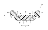
- the sheet pad 10 is formed of a foamed molded body.
- the foam molded article include a soft resin foam molded article obtained by foaming a resin material, such as a flexible polyurethane foam (soft resin).
- the seat pad 10 is employed, for example, in a seat (seat) attached to an automobile (vehicle).
- the seat pad 10 is provided with a seating surface 11 (mounting surface) on which an occupant seated on the seat abuts.
- a cushion pad is employed as the seat pad 10.
- the seating surface 11 faces the upper side in the vertical direction and extends along the front-rear direction and the left-right direction of the automobile. A passenger's load acts on the seat pad 10 from above.
- seat is formed in the flat rectangular parallelepiped shape.
- the direction orthogonal to the seating surface 11 in the seat pad 10 is the thickness direction H of the seat pad 10.
- seat is provided with the main-body part 12 (1st foam) and the side part 13 (2nd foam) integrally molded with a mutually different material.
- the body portion 12 has a lower hardness than the side portion 13.
- the side portion 13 is formed along the outer peripheral edge of the main body portion 12.
- the side portion 13 sandwiches the main body portion 12 from both sides in the seat width direction B (first lateral direction) along the seating surface 11.
- the seating surface 11 has a hanging groove 14 that extends along the seating surface 11 in an orthogonal direction (one direction) orthogonal to the seat width direction B.
- the suspension groove 14 is recessed from the seating surface 11 toward the counter seating surface side (counter mounting surface side) along the thickness direction H.
- the main body portion 12 and the side portion 13 are partitioned by a slit portion 15 and an intermittent hole 16.
- the slit portion 15 opens in a mounting surface 17 (back surface) which is a surface facing the opposite side of the seating surface 11 (the anti-seating surface side and the counter-mounting surface side) in the seat pad 10.
- the slit portion 15 is recessed upward from the mounting surface 17.
- the slit portion 15 extends from the inside to the outside of the sheet pad 10 along the sheet width direction B.
- the slit portion 15 gradually extends upward as it goes outward in the sheet width direction B.
- the inner end of the slit portion 15 in the sheet width direction B is open to the surface of the sheet pad 10.
- the outer end of the slit portion 15 in the sheet width direction B is not open on the surface of the sheet pad 10.
- a plurality of intermittent holes 16 are arranged at intervals in the orthogonal direction.
- the intermittent hole 16 opens in the seating surface 11.
- the intermittent hole 16 extends from the seating surface 11 toward the opposite seating surface side (mounting surface 17 side) along the thickness direction H.
- the end of the intermittent hole 16 is connected to the outer end of the slit portion 15 in the sheet width direction B.
- the main body portion 12 and the side portion 13 are partitioned in the sheet width direction B by the slit portion 15 and the intermittent hole 16.
- the side portion 13 is embedded in the opposite seating surface side (reverse mounting surface side) along the thickness direction H with respect to the main body portion 12 at both ends in the seat width direction B of the main body portion 12.
- the seat pad 10 when the occupant is seated on the seating surface 11, the seat pad 10 is deformed so that the slit portion 15 is narrowed in the thickness direction H. Accordingly, the sheet pad 10 can be appropriately bent while suppressing the hardness of the sheet. Thereby, for example, sitting comfort at the time of sitting or cornering can be improved. Moreover, since the slit part 15 has penetrated the pad 10 for sheets in the thickness direction H through the intermittent hole 16, air permeability can be improved.
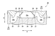
- the mold 20 includes a plurality of molds 21 and cavities 23.
- the cavity 23 is defined by a cavity surface 22 of each of the plurality of molds 21 between the plurality of molds 21.
- the cavity 23 has the same shape and the same size as the sheet pad 10.
- an upper mold 24 and a lower mold 25 are provided as the plurality of molding dies 21.
- the cavity surface 22 of the lower mold 25 is provided with a seating surface forming portion 26 (mounting surface forming portion) that forms the seating surface 11 of the seat pad 10.
- the plurality of molding dies 21 open and close in a thickness direction H (opening / closing direction of the plurality of molding dies) perpendicular to the seating surface forming portion 26 and along the vertical direction.
- a groove forming part 27, a protruding part 28 (slit forming part) and a holding part 29 are formed on the cavity surface 22 . That is, the mold 20 includes a groove forming part 27, a protruding part 28, and a holding part 29.
- the groove forming part 27 forms the hanging groove 14.
- the groove forming portion 27 protrudes from the seating surface forming portion 26 toward the upper mold 24 side.
- a pair of groove forming portions 27 are arranged at intervals in the seat width direction B along the seating surface forming portion 26. The pair of groove forming portions 27 have the same shape and the same size.
- the protrusion 28 is formed of an elastic body.
- the protruding portion 28 forms the slit portion 15 and forms a boundary surface between the main body portion 12 and the side portion 13.
- the protruding portion 28 is formed of, for example, PP (polypropylene), PET (polyethylene terephthalate), or the like, and is easily formed from the sheet pad 10 formed in the cavity 23.
- the protruding portion 28 protrudes from the cavity surface 22 into the cavity 23.
- the protruding portion 28 is formed on the cavity surface 22 of the upper mold 24 and protrudes from the upper mold 24 toward the lower mold 25.
- the protrusion 28 extends from the inside of the cavity 23 toward the outside along the sheet width direction B.
- the protruding portion 28 extends while being inclined with respect to the thickness direction H, and gradually extends toward the outer side in the sheet width direction B from the upper die 24 toward the lower die 25.
- the protrusion 28 is formed in a plate shape whose front and back surfaces are directed in the thickness direction H.
- the protrusions 28 extend straight along an orthogonal direction (one direction) perpendicular to the seat width direction B along the seating surface forming part 26 in a plan view of the cavity surface 22 on which the protrusions 28 are formed.
- a sliding portion 30 is formed at the tip of the protruding portion 28. The sliding portion 30 is formed by bending the leading end portion of the protruding portion 28 toward the outside in the sheet width direction B.
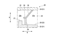
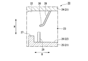
- the holding portion 29 abuts against the tip end portion of the protruding portion 28, in the example shown, the sliding portion 30 when the plurality of molds 21 are closed, and the protruding portion 28 is elastically deformed in the thickness direction H within the cavity 23.
- the holding portion 29 is provided on a cavity surface 22 that is different from the cavity surface 22 on which the protruding portions 28 are formed, among the cavity surfaces 22 of the plurality of molds 21.
- the holding portion 29 is formed of a rigid body and protrudes from the cavity surface 22.
- the holding portion 29 extends straight along the thickness direction H, and receives a reaction force from the protruding portion 28 in the thickness direction H.
- the holding portions 29 are formed in a columnar shape extending in the thickness direction H, and a plurality of holding portions 29 are arranged at intervals in the orthogonal direction.
- the projecting portion 28 and the holding portion 29 partition the cavity 23 into a first cavity 23 a that molds the main body portion 12 and a second cavity 23 b that molds the side portion 13.
- the first cavity 23 a is partitioned in the central portion of the cavity 23 in the sheet width direction B.
- the second cavities 23 b are partitioned at both side portions in the sheet width direction B in the cavities 23.
- the protruding portion 28 gradually extends toward the second cavity 23b as it goes toward the lower mold 25.
- the tip of the protruding portion 28 is held by the holding portion 29.
- the sheet pad 10 is formed.
- the plurality of molds 21 are opened, and the sheet pad 10 is removed from the cavity surface 22 while the protrusions 28 are elastically deformed. Thereby, the position of the protrusion part 28 in the cavity 23 can be maintained with high accuracy while making it easy to remove the sheet pad 10 from the cavity surface 22.
- the sliding portion 30 of the protruding portion 28 slides on the holding portion 29 so that the protruding portion 28 is moved in the thickness direction H. To be elastically deformed. At this time, the protruding portion 28 swings in the thickness direction H so as to be separated from the seating surface forming portion 26 around the base end portion of the protruding portion 28.
- the holding portion 29 is provided on the cavity surface 22. Therefore, the projecting portion 28 can be held from both the proximal end portion and the both end portions of the distal end portion by bringing the distal end portion of the projecting portion 28 into contact with the holding portion 29 in the cavity 23. Therefore, it is possible to restrict the protrusion 28 from being unexpectedly deformed and displaced in the cavity 23, and the position of the protrusion 28 in the cavity 23 can be maintained with high accuracy. Thereby, for example, the position of the boundary surface between the main body portion 12 and the side portion 13 and the position of the slit portion 15 can be accurately formed.
- the protruding portion 28 is formed of an elastic body. Therefore, when the plurality of molds 21 are opened after the sheet pad 10 is molded in the cavity 23, the sheet pad 10 can be removed from the cavity surface 22 while elastically deforming the protrusions 28. Therefore, when the sheet pad 10 is removed from the cavity surface 22, for example, it is possible to prevent the protruding portion 28 from being caught by the sheet pad 10. Accordingly, it is possible to easily remove the sheet pad 10 from the cavity surface 22 while preventing the sheet pad 10 from being damaged.
- the sheet pad 10 can be removed from the cavity surface 22 while elastically deforming the protruding portion 28. Therefore, it is possible to prevent an excessive load from being applied to the protruding portion 28 when the sheet pad 10 is removed, and the entire protruding portion 28 can be formed thin. Thereby, when the slit part 15 is formed in the pad 10 for sheet
- the holding portion 29 protrudes from the cavity surface 22. Therefore, for example, it is possible to suppress the tip portion of the projecting portion 28 from unintentionally coming into contact with a portion of the cavity surface 22 located around the holding portion 29. Thereby, it is possible to easily arrange the protruding portion 28 at a desired position in the cavity 23 with high accuracy.
- a plurality of holding portions 29 are arranged at intervals in the orthogonal direction. Therefore, the tip end portion of the projecting portion 28 can be firmly held by the holding portion 29, and the position of the projecting portion 28 in the cavity 23 can be maintained with higher accuracy.
- the protruding portion 28 extends while being inclined with respect to the thickness direction H, while the holding portion 29 extends straight along the thickness direction H. Therefore, when the plurality of molds 21 are closed, the protrusion 28 can be elastically deformed smoothly, and the position of the protrusion 28 in the cavity 23 can be maintained with higher accuracy. Further, when the sheet pad 10 is removed, the holding portion 29 can be easily detached from the sheet pad 10.
- the protruding portion 28 is formed on the cavity surface 22 of the lower mold 25 and protrudes from the lower mold 25 toward the upper mold 24. Therefore, the sheet pad 10 can be removed from the cavity surface 22 in the vertical direction, and the sheet pad 10 can be more easily removed from the cavity surface 22.
- the sliding portion 30 is provided on the protruding portion 28. Therefore, when the plurality of molds 21 are closed, the protrusion 28 can be elastically deformed smoothly, and the position of the protrusion 28 in the cavity 23 can be maintained with higher accuracy.
- the protrusion 28 may extend straight in the thickness direction H. Further, the protruding portion 28 may be provided on the lower die 25 and the holding portion 29 may be provided on the upper die 24.
- the holding part 29 does not need to protrude from the cavity surface 22, and may be constituted by the cavity surface 22, for example. Moreover, the sliding part 30 may not be present.
- the sheet pad 10 is integrally formed of different materials, but the present invention is not limited to this.
- the sheet pad 10 can be integrally formed of the same material.
- the slit portions 15 are separately provided at portions located on both sides of the sheet width direction B in the sheet pad 10, but the present invention is not limited to this.
- the slit portion 15 may be provided only on one side in the sheet width direction B.
- the present invention can be modified as appropriate to other forms in which one or a plurality of slit portions 15 are provided.
- the cushion pad is adopted as the seat pad 10 formed by the mold 20, the present invention is not limited to this.
- a back pad may be adopted as the seat pad 10, and seat pads for various uses such as indoor chairs and bedding cushion materials can be targeted.
- it is not limited to a person sitting, but may be a seat pad 10 having a placement surface on which luggage or the like is placed.
- die 20 which forms the foaming molding different from the pad 10 for sheets may be sufficient.
- the position of the protruding portion in the cavity can be maintained with high accuracy while ensuring the demoldability of the foamed molded product.
Landscapes
- Engineering & Computer Science (AREA)
- Mechanical Engineering (AREA)
- Aviation & Aerospace Engineering (AREA)
- Transportation (AREA)
- Manufacturing & Machinery (AREA)
- Moulds For Moulding Plastics Or The Like (AREA)
- Casting Or Compression Moulding Of Plastics Or The Like (AREA)
- Molding Of Porous Articles (AREA)
- Mattresses And Other Support Structures For Chairs And Beds (AREA)
Abstract
発泡成形体の製造装置(20)は、複数の成形型(21)と、複数の成形型(21)の間に、複数の成形型(21)それぞれのキャビティ面(22)によって画成されるキャビティ(23)と、キャビティ面(22)に形成された突出部(28)と、を備える。突出部(28)は、弾性体により形成されている。キャビティ面(22)には、複数の成形型(21)が型閉じするときに突出部(28)の先端部に当接し、突出部(28)をキャビティ(23)内で弾性変形させる保持部(29)が設けられている。
Description
本発明は、発泡成形体の製造装置、発泡成形体の製造方法および発泡成形体に関する。
本願は、2015年5月28日に、日本に出願された特願2015-108155号に基づき優先権を主張し、その内容をここに援用する。
本願は、2015年5月28日に、日本に出願された特願2015-108155号に基づき優先権を主張し、その内容をここに援用する。
従来から、例えば下記特許文献1に記載された発泡成形体の製造装置が知られている。この製造装置は、複数の成形型の間に、複数の成形型それぞれのキャビティ面によって画成されるキャビティを備えている。キャビティ面には突出部が形成されている。
前記従来の発泡成形体の製造装置では、キャビティ内で発泡成形体を成形した後に複数の成形型を型開きし、発泡成形体をキャビティ面から脱型させる。このとき、発泡成形体の脱型性を確保しつつ、キャビティ内における突出部の位置を高精度に維持することについて改善の余地がある。
本発明は、前述した事情に鑑みてなされたものであって、発泡成形体の脱型性を確保しつつ、キャビティ内における突出部の位置を高精度に維持することを目的とする。
前記課題を解決するために、本発明は以下の手段を提案している。
本発明に係る発泡成形体の製造装置は、複数の成形型と、複数の成形型の間に、前記複数の成形型それぞれのキャビティ面によって画成されるキャビティと、前記キャビティ面に形成された突出部と、を備える。前記突出部は、弾性体により形成されている。前記キャビティ面には、前記複数の成形型が型閉じするときに前記突出部の先端部に当接し、前記突出部を前記キャビティ内で弾性変形させる保持部が設けられている。
本発明に係る発泡成形体の製造装置は、複数の成形型と、複数の成形型の間に、前記複数の成形型それぞれのキャビティ面によって画成されるキャビティと、前記キャビティ面に形成された突出部と、を備える。前記突出部は、弾性体により形成されている。前記キャビティ面には、前記複数の成形型が型閉じするときに前記突出部の先端部に当接し、前記突出部を前記キャビティ内で弾性変形させる保持部が設けられている。
本発明によれば、発泡成形体の脱型性を確保しつつ、キャビティ内における突出部の位置を高精度に維持することができる。
以下、本発明の一実施形態に係るシート用パッド10を、図1から図4を参照して説明する。
図1に示すように、シート用パッド10は、発泡成形体によりに形成される。発泡成形体としては、樹脂材料を発泡させて成形した軟質の樹脂発泡成形体、例えば軟質ポリウレタンフォーム(軟質樹脂)等が挙げられる。
図1に示すように、シート用パッド10は、発泡成形体によりに形成される。発泡成形体としては、樹脂材料を発泡させて成形した軟質の樹脂発泡成形体、例えば軟質ポリウレタンフォーム(軟質樹脂)等が挙げられる。
シート用パッド10は、例えば自動車(車両)に取り付けられるシート(座席)に採用される。シート用パッド10には、シートに着座する乗員が当接する着座面11(載置面)が設けられている。本実施形態では、シート用パッド10として、クッションパッドを採用している。シート用パッド10が自動車に取り付けられた状態で、着座面11は、鉛直方向の上側を向くとともに自動車の前後方向および左右方向に沿う。シート用パッド10には、乗員の荷重が上側から作用する。
シート用パッド10は、偏平直方体状に形成されている。シート用パッド10において着座面11に直交する方向は、シート用パッド10の厚さ方向Hになっている。
シート用パッド10は、互いに異なる材質で一体に成形された本体部12(第1発泡体)およびサイド部13(第2発泡体)を備えている。本体部12は、サイド部13よりも硬度が低い。サイド部13は、本体部12の外周縁に沿って形成されている。サイド部13は、本体部12を、着座面11に沿うシート幅方向B(第1横方向)の両側から挟み込んでいる。着座面11には、着座面11に沿いシート幅方向Bに直交する直交方向(一方向)に延びる吊溝14が開口している。吊溝14は、着座面11から厚さ方向Hに沿う反着座面側(反載置面側)に向けて窪んでいる。
シート用パッド10は、互いに異なる材質で一体に成形された本体部12(第1発泡体)およびサイド部13(第2発泡体)を備えている。本体部12は、サイド部13よりも硬度が低い。サイド部13は、本体部12の外周縁に沿って形成されている。サイド部13は、本体部12を、着座面11に沿うシート幅方向B(第1横方向)の両側から挟み込んでいる。着座面11には、着座面11に沿いシート幅方向Bに直交する直交方向(一方向)に延びる吊溝14が開口している。吊溝14は、着座面11から厚さ方向Hに沿う反着座面側(反載置面側)に向けて窪んでいる。
本体部12とサイド部13とは、スリット部15および間欠孔16により区画されている。スリット部15は、シート用パッド10において着座面11の反対側(反着座面側、反載置面側)を向く面である取付け面17(裏面)に開口している。スリット部15は、取付け面17から上側に向けて窪んでいる。スリット部15は、シート幅方向Bに沿って当該シート用パッド10の内側から外側に向けて延びている。スリット部15は、シート幅方向Bの外側に向かうに従い漸次、上側に向けて延びている。
スリット部15におけるシート幅方向Bの内側の端部は、シート用パッド10の表面に開口している。スリット部15におけるシート幅方向Bの外側の端部は、シート用パッド10の表面に非開口となっている。
間欠孔16は、直交方向に間隔をあけて複数配置されている。間欠孔16は、着座面11に開口している。間欠孔16は、着座面11から厚さ方向Hに沿う反着座面側(取付け面17側)に向けて延びている。間欠孔16の端部は、スリット部15におけるシート幅方向Bの外側の端部に接続されている。
間欠孔16は、直交方向に間隔をあけて複数配置されている。間欠孔16は、着座面11に開口している。間欠孔16は、着座面11から厚さ方向Hに沿う反着座面側(取付け面17側)に向けて延びている。間欠孔16の端部は、スリット部15におけるシート幅方向Bの外側の端部に接続されている。
本体部12とサイド部13とは、スリット部15および間欠孔16よってシート幅方向Bに仕切られている。サイド部13は、本体部12におけるシート幅方向Bの両端部において、本体部12に対して、厚さ方向Hに沿う反着座面側(反載置面側)に潜り込んでいる。
このようなシート用パッド10によれば、着座面11上に乗員が着座したときに、スリット部15を厚さ方向Hに狭めるように、シート用パッド10を変形させることで、シート用パッド10から感じる硬さを抑えつつシート用パッド10を適度に撓ませることが可能になる。これにより、例えば着座時やコーナリング時などの座り心地性を向上させることができる。
またスリット部15が、間欠孔16を通してシート用パッド10を厚さ方向Hに貫通しているので、通気性を高めることができる。
またスリット部15が、間欠孔16を通してシート用パッド10を厚さ方向Hに貫通しているので、通気性を高めることができる。
次に、前記シート用パッド10を形成する金型20(発泡成形体の製造装置)について説明する。
図2および図3に示すように、金型20は、複数の成形型21と、キャビティ23と、を備えている。キャビティ23は、複数の成形型21の間に、複数の成形型21それぞれのキャビティ面22によって画成される。キャビティ23は、シート用パッド10と同等の形状でかつ同等の大きさに形成されている。本実施形態では、複数の成形型21として、上型24および下型25を備えている。下型25のキャビティ面22には、シート用パッド10の着座面11を形成する着座面形成部26(載置面形成部)が設けられている。複数の成形型21は、着座面形成部26に直交し鉛直方向に沿う厚さ方向H(複数の成形型の開閉方向)に開閉する。
キャビティ面22には、溝形成部27、突出部28(スリット形成部)および保持部29が形成されている。つまり金型20は、溝形成部27、突出部28および保持部29を備えている。
溝形成部27は、吊溝14を形成する。溝形成部27は、着座面形成部26から上型24側に向けて突出している。溝形成部27は、着座面形成部26に沿うシート幅方向Bに間隔をあけて一対配置されている。一対の溝形成部27は、互いに同等の形状で同等の大きさに形成されている。
溝形成部27は、吊溝14を形成する。溝形成部27は、着座面形成部26から上型24側に向けて突出している。溝形成部27は、着座面形成部26に沿うシート幅方向Bに間隔をあけて一対配置されている。一対の溝形成部27は、互いに同等の形状で同等の大きさに形成されている。
突出部28は、弾性体により形成されている。突出部28は、スリット部15を形成するとともに、本体部12とサイド部13との境界面を形成する。本実施形態では、突出部28は、例えば、PP(ポリプロピレン)やPET(ポリエチレンテレフタラート)等により形成され、キャビティ23内に成形されるシート用パッド10から脱離容易に形成されている。
突出部28は、キャビティ面22からキャビティ23内に突出している。突出部28は、上型24のキャビティ面22に形成され、上型24から下型25に向けて突出している。突出部28は、シート幅方向Bに沿って、キャビティ23の内側から外側に向けて延びている。突出部28は、厚さ方向Hに対して傾斜して延び、上型24から下型25に向かうに従い漸次、シート幅方向Bの外側に向けて延びている。
突出部28は、表裏面が厚さ方向Hを向く板状に形成されている。突出部28は、突出部28が形成されたキャビティ面22の平面視において、着座面形成部26に沿いシート幅方向Bに直交する直交方向(一方向)に沿って真直に延びている。
突出部28の先端部には、摺動部30が形成されている。摺動部30は、突出部28の先端部がシート幅方向Bの外側に向けて屈曲されることで形成されている。
突出部28の先端部には、摺動部30が形成されている。摺動部30は、突出部28の先端部がシート幅方向Bの外側に向けて屈曲されることで形成されている。
保持部29は、複数の成形型21が型閉じするときに突出部28の先端部、図示の例では摺動部30に当接し、突出部28をキャビティ23内で厚さ方向Hに弾性変形させる。保持部29は、複数の成形型21それぞれのキャビティ面22のうち、突出部28が形成されたキャビティ面22とは異なるキャビティ面22に設けられている。保持部29は、剛体により形成され、キャビティ面22から突出している。保持部29は、厚さ方向Hに沿って真直に延び、突出部28から厚さ方向Hに向けた反力を受け止める。保持部29は、厚さ方向Hに延びる円柱状に形成され、直交方向に間隔をあけて複数配置されている。
突出部28および保持部29は、キャビティ23を、本体部12を成形する第1キャビティ23aと、サイド部13を成形する第2キャビティ23bと、に仕切る。第1キャビティ23aは、キャビティ23におけるシート幅方向Bの中央部分に区画されている。第2キャビティ23bは、キャビティ23におけるシート幅方向Bの両側部分に区画される。突出部28は、下型25側に向かうに従い漸次、第2キャビティ23b側に向けて延びている。
前記金型20を用いて前記シート用パッド10を形成するシート用パッドの製造方法(発泡成形体の製造方法)では、図2に示すように、保持部29により突出部28の先端部を保持させたキャビティ23内で、シート用パッド10を成形する。その後、複数の成形型21を型開きし、突出部28を弾性変形させながらシート用パッド10をキャビティ面22から脱型させる。これにより、シート用パッド10をキャビティ面22から脱型させ易くしつつ、キャビティ23内における突出部28の位置を高精度に維持することができる。
なお、図3および図4に示すように、複数の成形型21が型閉じするときには、突出部28の摺動部30が保持部29上を摺動することで突出部28を厚さ方向Hに弾性変形させる。このとき、突出部28は、突出部28の基端部を中心として着座面形成部26から離間するように厚さ方向Hに揺動する。
以上説明したように、本実施形態に係る金型20によれば、キャビティ面22に、保持部29が設けられている。したがって、キャビティ23内で突出部28の先端部を保持部29に当接させることで、突出部28を、基端部および先端部の両端部から保持することができる。したがって、キャビティ23内で突出部28が予期せず変形、変位するのを規制することが可能になり、キャビティ23内における突出部28の位置を高精度に維持することができる。これにより、例えば、本体部12とサイド部13との境界面の位置やスリット部15の位置を精度良く形成すること等ができる。
しかも突出部28が、弾性体により形成されている。よって、キャビティ23内でシート用パッド10を成形した後に複数の成形型21を型開きしたときに、突出部28を弾性変形させながらシート用パッド10をキャビティ面22から脱型させることができる。したがって、シート用パッド10をキャビティ面22から脱型させるときに、例えば突出部28がシート用パッド10に引っかかるのを抑えること等が可能になる。これにより、シート用パッド10に損傷が生じるのを抑えつつ、シート用パッド10をキャビティ面22から脱型させ易くすることができる。
また前述のように、突出部28を弾性変形させながらシート用パッド10をキャビティ面22から脱型させることができる。したがって、シート用パッド10の脱型時に、突出部28に過度な負荷がかかるのを抑えることが可能になり、突出部28の全体を薄肉に形成することができる。これにより、例えば突出部28によってシート用パッド10にスリット部15を形成する場合、スリット部15の薄さを自由度高く設定することができる。
また保持部29が、キャビティ面22から突出している。したがって、例えば、突出部28の先端部が、キャビティ面22のうち、保持部29の周辺に位置する部分に意図せず当接するのを抑えることが可能になる。これにより、キャビティ23内において突出部28を所望の位置に精度良く配置し易くすることができる。
また保持部29が、直交方向に間隔をあけて複数配置されている。したがって、突出部28の先端部を保持部29によって強固に保持することが可能になり、キャビティ23内における突出部28の位置を一層高精度に維持することができる。
また突出部28が、厚さ方向Hに対して傾斜して延びるのに対して、保持部29が、厚さ方向Hに沿って真直に延びている。したがって、複数の成形型21を型閉じするときに、突出部28を円滑に弾性変形させることが可能になり、キャビティ23内における突出部28の位置を一層高精度に維持することができる。またシート用パッド10の脱型時に、シート用パッド10から保持部29を容易に脱離させることができる。
また突出部28が、下型25のキャビティ面22に形成され、下型25から上型24に向けて突出している。したがって、シート用パッド10をキャビティ面22から鉛直方向に引き離すことで脱型させることが可能になり、シート用パッド10をキャビティ面22からより脱型させ易くすることができる。
また、突出部28に摺動部30が設けられている。したがって、複数の成形型21を型閉じするときに、突出部28を円滑に弾性変形させることが可能になり、キャビティ23内における突出部28の位置を一層高精度に維持することができる。
なお、本発明の技術的範囲は前記実施形態に限定されるものではなく、本発明の趣旨を逸脱しない範囲において種々の変更を加えることが可能である。
例えば、突出部28は、厚さ方向Hに真直に延びていてもよい。また突出部28が下型25に設けられ、保持部29が上型24に設けられていてもよい。保持部29はキャビティ面22から突出していなくてもよく、例えばキャビティ面22により構成されていてもよい。また摺動部30がなくてもよい。
前記実施形態では、シート用パッド10は、異種材料により一体に形成されているが、本発明はこれに限られない。例えば、シート用パッド10を同一材料により一体に形成することも可能である。
前記実施形態では、スリット部15は、シート用パッド10において、シート幅方向Bの両側に位置する部分に各別に設けられているが、本発明はこれに限られない。スリット部15が、シート幅方向Bの片側にのみ設けられていてもよい。スリット部15が1つまたは複数設けられた他の形態に、本発明を適宜変更することが可能である。
金型20により形成されるシート用パッド10として、クッションパッドを採用したが、本発明はこれに限られない。例えば、シート用パッド10としてバックパッドを採用してもよく、室内用の椅子や寝具のクッション材などの様々な用途のシート用パッドを対象とすることが可能である。さらに、人が着座することに限らず、荷物等を載置する載置面を有するシート用パッド10であってもよい。さらにまた、シート用パッド10と異なる発泡成形体を形成する金型20であってもよい。
その他、本発明の趣旨に逸脱しない範囲で、前記実施形態における構成要素を周知の構成要素に置き換えることは適宜可能であり、また、前記した変形例を適宜組み合わせてもよい。
本発明に係る発泡成形体の製造装置によれば、発泡成形体の脱型性を確保しつつ、キャビティ内における突出部の位置を高精度に維持することができる。
10 シート用パッド
20 金型(発泡成形体の製造装置)
21 成形型
22 キャビティ面
23 キャビティ
24 上型
25 下型
28 突出部
29 保持部
30 摺動部
20 金型(発泡成形体の製造装置)
21 成形型
22 キャビティ面
23 キャビティ
24 上型
25 下型
28 突出部
29 保持部
30 摺動部
Claims (8)
- 複数の成形型と、
前記複数の成形型の間に、前記複数の成形型それぞれのキャビティ面によって画成されるキャビティと、
前記キャビティ面に形成された突出部と、を備える発泡成形体の製造装置であって、
前記突出部は、弾性体により形成され、
前記キャビティ面には、前記複数の成形型が型閉じするときに前記突出部の先端部に当接し、前記突出部を前記キャビティ内で弾性変形させる保持部が設けられている発泡成形体の製造装置。 - 前記保持部は、前記キャビティ面から突出している請求項1記載の発泡成形体の製造装置。
- 前記突出部は、前記突出部が形成された前記キャビティ面の平面視において、一方向に延び、
前記保持部は、前記一方向に間隔をあけて複数配置されている請求項2記載の発泡成形体の製造装置。 - 前記突出部は、前記複数の成形型の開閉方向に対して傾斜して延び、
前記保持部は、前記開閉方向に沿って真直に延びている請求項2または3に記載の発泡成形体の製造装置。 - 前記複数の成形型として、上型および下型が備えられ、
前記突出部は、前記上型の前記キャビティ面に形成され、前記上型から前記下型に向けて突出し、
前記保持部は、前記下型の前記キャビティ面に設けられている請求項1から4のいずれか1項に記載の発泡成形体の製造装置。 - 前記突出部には、前記複数の成形型が型閉じするときに前記保持部上を摺動することで前記突出部を弾性変形させる摺動部が設けられている請求項1から5のいずれか1項に記載の発泡成形体の製造装置。
- 請求項1から6のいずれか1項に記載の発泡成形体の製造装置を用いて発泡成形体を形成する発泡成形体の製造方法であって、
前記保持部により前記突出部の先端部を保持させた前記キャビティ内で、前記発泡成形体を成形した後、前記複数の成形型を型開きし、前記突出部を弾性変形させながら前記発泡成形体を前記キャビティ面から脱型させる発泡成形体の製造方法。 - 請求項7記載の発泡成形体の製造方法により形成されたことを特徴とする発泡成形体。
Priority Applications (2)
| Application Number | Priority Date | Filing Date | Title |
|---|---|---|---|
| US15/571,167 US20180111292A1 (en) | 2015-05-28 | 2016-04-22 | Foam molded body production device, foam molded body production method, and foam molded body |
| CN201680029658.2A CN107614231A (zh) | 2015-05-28 | 2016-04-22 | 发泡成型体制造装置、发泡成型体制造方法和发泡成型体 |
Applications Claiming Priority (2)
| Application Number | Priority Date | Filing Date | Title |
|---|---|---|---|
| JP2015108155A JP6484110B2 (ja) | 2015-05-28 | 2015-05-28 | 発泡成形体の製造装置および発泡成形体の製造方法 |
| JP2015-108155 | 2015-05-28 |
Publications (1)
| Publication Number | Publication Date |
|---|---|
| WO2016190020A1 true WO2016190020A1 (ja) | 2016-12-01 |
Family
ID=57393124
Family Applications (1)
| Application Number | Title | Priority Date | Filing Date |
|---|---|---|---|
| PCT/JP2016/062838 Ceased WO2016190020A1 (ja) | 2015-05-28 | 2016-04-22 | 発泡成形体の製造装置、発泡成形体の製造方法および発泡成形体 |
Country Status (4)
| Country | Link |
|---|---|
| US (1) | US20180111292A1 (ja) |
| JP (1) | JP6484110B2 (ja) |
| CN (1) | CN107614231A (ja) |
| WO (1) | WO2016190020A1 (ja) |
Families Citing this family (1)
| Publication number | Priority date | Publication date | Assignee | Title |
|---|---|---|---|---|
| US11571843B2 (en) * | 2017-05-16 | 2023-02-07 | Archem Inc. | Foam molding mold and method for manufacturing foam molding body |
Citations (3)
| Publication number | Priority date | Publication date | Assignee | Title |
|---|---|---|---|---|
| JPH07205222A (ja) * | 1994-01-25 | 1995-08-08 | Sanyo Electric Co Ltd | 射出成形金型 |
| JP2008080628A (ja) * | 2006-09-27 | 2008-04-10 | Bridgestone Corp | 車両用シートパッドの製造方法 |
| JP2011000731A (ja) * | 2009-06-16 | 2011-01-06 | Bridgestone Corp | 発泡成形用金型 |
Family Cites Families (2)
| Publication number | Priority date | Publication date | Assignee | Title |
|---|---|---|---|---|
| JP5017816B2 (ja) * | 2005-08-18 | 2012-09-05 | 株式会社ブリヂストン | 車両用シートパッド |
| JP5951439B2 (ja) * | 2012-10-05 | 2016-07-13 | 東洋ゴム工業株式会社 | シート用バックパッド及びその製造方法 |
-
2015
- 2015-05-28 JP JP2015108155A patent/JP6484110B2/ja not_active Expired - Fee Related
-
2016
- 2016-04-22 WO PCT/JP2016/062838 patent/WO2016190020A1/ja not_active Ceased
- 2016-04-22 CN CN201680029658.2A patent/CN107614231A/zh active Pending
- 2016-04-22 US US15/571,167 patent/US20180111292A1/en not_active Abandoned
Patent Citations (3)
| Publication number | Priority date | Publication date | Assignee | Title |
|---|---|---|---|---|
| JPH07205222A (ja) * | 1994-01-25 | 1995-08-08 | Sanyo Electric Co Ltd | 射出成形金型 |
| JP2008080628A (ja) * | 2006-09-27 | 2008-04-10 | Bridgestone Corp | 車両用シートパッドの製造方法 |
| JP2011000731A (ja) * | 2009-06-16 | 2011-01-06 | Bridgestone Corp | 発泡成形用金型 |
Also Published As
| Publication number | Publication date |
|---|---|
| CN107614231A (zh) | 2018-01-19 |
| JP2016221739A (ja) | 2016-12-28 |
| JP6484110B2 (ja) | 2019-03-13 |
| US20180111292A1 (en) | 2018-04-26 |
Similar Documents
| Publication | Publication Date | Title |
|---|---|---|
| CN107614318B (zh) | 座垫和座垫制造装置 | |
| US10166892B2 (en) | Pad | |
| JP5951439B2 (ja) | シート用バックパッド及びその製造方法 | |
| JP2009297285A (ja) | シートパッド、その成形方法及び金型 | |
| EP3305585B1 (en) | Seat pad | |
| JP6484110B2 (ja) | 発泡成形体の製造装置および発泡成形体の製造方法 | |
| JP6532756B2 (ja) | 発泡成形体の製造装置、発泡成形体の製造方法 | |
| EP3305584B1 (en) | Seat pad | |
| JP6211267B2 (ja) | 車両用シートパッド | |
| JP2010184085A (ja) | 車両用シートパッド | |
| JP6768257B2 (ja) | シートパッドの製造方法 | |
| JP5518417B2 (ja) | 車両用シートパッド | |
| US10414308B2 (en) | Vehicle seat and manufacturing method thereof | |
| JP6436858B2 (ja) | シート用パッドおよびシート用パッドの製造装置 | |
| JP6252743B2 (ja) | シートバックの構造 | |
| JP5442511B2 (ja) | シートパッドの製造方法 | |
| JP7269751B2 (ja) | シートパッドおよびその製造方法、成形型 | |
| WO2009150939A1 (ja) | シートパッド、その成形方法及び金型 | |
| CN105584396A (zh) | 座垫 | |
| JP2007054384A (ja) | 車両用シートパッド | |
| JP2019024939A (ja) | シート用パッドおよび座席シート | |
| JP2012206310A (ja) | 発泡合成樹脂成形体 | |
| JP2009061687A (ja) | 成形用金型及び樹脂発泡成形体の成形方法 |
Legal Events
| Date | Code | Title | Description |
|---|---|---|---|
| 121 | Ep: the epo has been informed by wipo that ep was designated in this application |
Ref document number: 16799728 Country of ref document: EP Kind code of ref document: A1 |
|
| WWE | Wipo information: entry into national phase |
Ref document number: 15571167 Country of ref document: US |
|
| NENP | Non-entry into the national phase |
Ref country code: DE |
|
| 122 | Ep: pct application non-entry in european phase |
Ref document number: 16799728 Country of ref document: EP Kind code of ref document: A1 |