WO2016190033A1 - Stator de dispositif électrique tournant - Google Patents
Stator de dispositif électrique tournant Download PDFInfo
- Publication number
- WO2016190033A1 WO2016190033A1 PCT/JP2016/063124 JP2016063124W WO2016190033A1 WO 2016190033 A1 WO2016190033 A1 WO 2016190033A1 JP 2016063124 W JP2016063124 W JP 2016063124W WO 2016190033 A1 WO2016190033 A1 WO 2016190033A1
- Authority
- WO
- WIPO (PCT)
- Prior art keywords
- stator
- coil
- rotating electrical
- electrical machine
- parallel
- Prior art date
- Legal status (The legal status is an assumption and is not a legal conclusion. Google has not performed a legal analysis and makes no representation as to the accuracy of the status listed.)
- Ceased
Links
Images


Classifications
-
- H—ELECTRICITY
- H02—GENERATION; CONVERSION OR DISTRIBUTION OF ELECTRIC POWER
- H02K—DYNAMO-ELECTRIC MACHINES
- H02K3/00—Details of windings
- H02K3/04—Windings characterised by the conductor shape, form or construction, e.g. with bar conductors
-
- H—ELECTRICITY
- H02—GENERATION; CONVERSION OR DISTRIBUTION OF ELECTRIC POWER
- H02K—DYNAMO-ELECTRIC MACHINES
- H02K1/00—Details of the magnetic circuit
- H02K1/06—Details of the magnetic circuit characterised by the shape, form or construction
- H02K1/12—Stationary parts of the magnetic circuit
- H02K1/16—Stator cores with slots for windings
- H02K1/165—Shape, form or location of the slots
-
- H—ELECTRICITY
- H02—GENERATION; CONVERSION OR DISTRIBUTION OF ELECTRIC POWER
- H02K—DYNAMO-ELECTRIC MACHINES
- H02K3/00—Details of windings
- H02K3/46—Fastening of windings on the stator or rotor structure
- H02K3/48—Fastening of windings on the stator or rotor structure in slots
-
- H—ELECTRICITY
- H02—GENERATION; CONVERSION OR DISTRIBUTION OF ELECTRIC POWER
- H02K—DYNAMO-ELECTRIC MACHINES
- H02K5/00—Casings; Enclosures; Supports
- H02K5/04—Casings or enclosures characterised by the shape, form or construction thereof
- H02K5/20—Casings or enclosures characterised by the shape, form or construction thereof with channels or ducts for flow of cooling medium
- H02K5/203—Casings or enclosures characterised by the shape, form or construction thereof with channels or ducts for flow of cooling medium specially adapted for liquids, e.g. cooling jackets
Definitions
- the present invention relates to a rotating electrical machine, and more particularly to the structure of a stator of the rotating electrical machine.
- Each material constituting the rotating electrical machine has an upper limit temperature, and when operating as an electric motor or a generator, it is necessary to cool each part so that the temperature does not exceed the upper limit temperature.
- the large loss of the rotating electrical machine means that a larger input is required to obtain a certain output, and reduction of the loss is also required from the viewpoint of efficiency.
- the means for reducing the loss of the rotating electrical machine it is known to improve the space factor by inserting a plurality of substantially U-shaped segment conductors into slots provided in the stator core. 1 and 2 and the like. Focusing on the loss of the coil winding of the stator, it can be divided into so-called Joule loss that occurs when a current flows through the coil winding, and eddy current loss caused by the rotating magnetic field generated by the rotation of the rotor.
- Joule loss is proportional to the product of the square of the current flowing through the coil winding and the electrical resistance of the coil winding.
- the eddy current loss is proportional to the square of the current flowing through the coil winding and the square of the radial height of the coil winding.
- An object of the present invention is to provide a stator for a rotating electrical machine that is highly efficient and has excellent cooling performance, and a rotating electrical machine that uses the stator.
- the present application includes a plurality of means for solving the above-mentioned problems.
- a stator core provided with a plurality of slots and a coil formed by inserting segment conductors and connecting segment conductors. And two or more coil windings that are electrically connected in parallel and the coil winding that is electrically connected in series with the coil windings connected in parallel.
- the stator is characterized in that a wire is inserted.
- an electric motor for driving an electric vehicle is used as an example of a rotating electric machine.
- FIG. 1 is a cross-sectional view of a rotating electrical machine having a stator according to the present invention cut along a plane parallel to the rotation axis.
- the rotating electrical machine 10 includes a stator core 21, a stator 20 composed of a stator winding coil 23 wound around a stator slot 22 provided in the axial direction of the stator core, a rotor core 31, A rotor 30 constituted by a permanent magnet 32 embedded in the rotor core, a bearing 33 that rotatably supports the rotor 30, a bracket 42 that holds the bearing, and a housing 40 that holds the stator. Is done.
- liquid cooling jacket 41 for cooling the stator 20 is provided in the housing 40 in FIG. 1, it is not always necessary to provide the liquid cooling jacket.
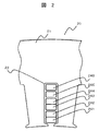
- FIG. 2 is a cross-sectional view of the stator 20 according to the present invention cut along a plane perpendicular to the rotation axis.
- a plurality of stator winding coils 23 are inserted into the stator slot 22 of the stator 20.
- the coils 241 and 242, 243 and 244 on the inner diameter side in the stator slot 22 are mutually connected. It is connected at the end in the rotation axis direction.
- stator winding coils (241 to 246) are inserted into the stator slot 22, but electrically, four stator winding coils (251 to 254) shown in FIG. Is equivalent to the inserted stator.
- stator slots 22 in FIGS. 2 and 3 have the same dimensions.
- the ratio (space factor) occupied by the stator windings in the stator slot 22 of FIGS. 2 and 3 is equal.
- the cross-sectional dimensions of the six stator winding coils (241 to 246) in FIG. 2 are equal.
- the cross-sectional dimensions of the four stator winding coils (251 to 254) in FIG. 3 are equal.
- the eddy current loss that occurs in the stator winding coil is proportional to the product of the square of the current flowing through the stator winding coil and the square of the radial thickness, and is the most inner diameter side in the stator slot. It occurs only in the coil.
- the ratio of the radial thickness is the ratio of the cross-sectional area per stator winding coil.
- the ratio of the radial thickness of the stator winding coil is equal to the ratio of the electrical resistance of the stator winding coil.
- the electric resistance per one of the six stator winding coils (241 to 246) in FIG. 2 is R ⁇ 6 ⁇ 4 because it is inversely proportional to the cross-sectional area.
- stator winding coil I / 2 for the coils (241 to 244) connected in parallel, and I for the coils (245 and 245) connected in series.
- FIG. 4 shows the loss obtained by electromagnetic field analysis and the temperature rise performed using the loss.
- the “loss ratio” is the ratio of the loss of the present embodiment shown in FIG. 2 to the loss of the structure shown in FIG. 3
- the “temperature rise ratio” is the maximum of the present embodiment shown in FIG. If the ratio of the temperature rise to the maximum temperature rise of the structure shown in FIG. 3 is less than 100%, the numerical value in the present embodiment shown in FIG. 2 is small.
- the loss ratio is smaller than 100% under any condition, and the loss of this example is small, that is, the efficiency is improved.
- the temperature rise is less than 100% under three conditions except for the condition of the rotational speed of 3000 [min ⁇ (-1)], and the temperature rise of this embodiment is kept low.
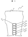
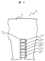
- winding coils (261 and 262) out of five winding coils (261 to 265) may be connected in parallel as shown in FIG. 5, or six winding coils as shown in FIG. Of the winding coils (271 to 276), three winding coils (271 to 273) may be connected in parallel.
- the coils located on the inner diameter side in the stator slot 22 are connected in parallel, but this is not particularly limited.
- the loss of the winding coil located at a further distance from the liquid cooling jacket is reduced.
- it is very effective in reducing the maximum temperature rise. Therefore, as shown in FIG. 2 and the like, it is preferable to connect the winding coils on the inner diameter side in the stator slot 22 in parallel from the viewpoint of reducing the temperature rise.
Landscapes
- Engineering & Computer Science (AREA)
- Power Engineering (AREA)
- Windings For Motors And Generators (AREA)
Abstract
L'invention concerne un stator de dispositif électrique tournant présentant une efficacité élevée et d'excellentes performances de refroidissement. Le stator de la présente invention comprend un noyau de stator pourvu d'une pluralité d'encoches et d'enroulements de bobine qui sont introduits dans les encoches et formés connectés à un conducteur de segment, et est caractérisé en ce qu'au moins deux des enroulements de bobine qui sont électriquement connectés en parallèle, et des enroulements de bobine qui sont électriquement connectés en série avec les enroulements de bobine qui sont électriquement connectés en parallèle, sont introduits dans les encoches.
Priority Applications (2)
| Application Number | Priority Date | Filing Date | Title |
|---|---|---|---|
| US15/573,878 US20180294686A1 (en) | 2015-05-22 | 2016-04-27 | Stator for Rotating Electric Machine |
| CN201680025774.7A CN107615621B (zh) | 2015-05-22 | 2016-04-27 | 旋转电机的定子 |
Applications Claiming Priority (2)
| Application Number | Priority Date | Filing Date | Title |
|---|---|---|---|
| JP2015104121A JP6591198B2 (ja) | 2015-05-22 | 2015-05-22 | 回転電機の固定子 |
| JP2015-104121 | 2015-05-22 |
Publications (1)
| Publication Number | Publication Date |
|---|---|
| WO2016190033A1 true WO2016190033A1 (fr) | 2016-12-01 |
Family
ID=57393142
Family Applications (1)
| Application Number | Title | Priority Date | Filing Date |
|---|---|---|---|
| PCT/JP2016/063124 Ceased WO2016190033A1 (fr) | 2015-05-22 | 2016-04-27 | Stator de dispositif électrique tournant |
Country Status (4)
| Country | Link |
|---|---|
| US (1) | US20180294686A1 (fr) |
| JP (1) | JP6591198B2 (fr) |
| CN (1) | CN107615621B (fr) |
| WO (1) | WO2016190033A1 (fr) |
Families Citing this family (4)
| Publication number | Priority date | Publication date | Assignee | Title |
|---|---|---|---|---|
| US10454322B2 (en) * | 2017-06-27 | 2019-10-22 | Hitachi Automotive Systems, Ltd. | Dynamo-electric machine |
| TWI697175B (zh) * | 2018-12-28 | 2020-06-21 | 台達電子工業股份有限公司 | 馬達定子 |
| US11381129B2 (en) | 2018-12-28 | 2022-07-05 | Delta Electronics, Inc. | Motor stator with winding configuration using hairpin wires |
| JP7468301B2 (ja) | 2020-11-04 | 2024-04-16 | 株式会社デンソー | 回転電機 |
Citations (3)
| Publication number | Priority date | Publication date | Assignee | Title |
|---|---|---|---|---|
| JPH11346448A (ja) * | 1997-09-26 | 1999-12-14 | Denso Corp | 車両用交流発電機の固定子 |
| JP2005287109A (ja) * | 2004-03-29 | 2005-10-13 | Mitsubishi Electric Corp | 回転電機の固定子 |
| JP2014100037A (ja) * | 2012-11-16 | 2014-05-29 | Hitachi Automotive Systems Ltd | 回転電機の固定子 |
Family Cites Families (5)
| Publication number | Priority date | Publication date | Assignee | Title |
|---|---|---|---|---|
| DE2409681A1 (de) * | 1974-02-28 | 1975-09-11 | Retobobina Handelsanstalt | Elektrische ankerwicklung |
| JP3407643B2 (ja) * | 1997-05-26 | 2003-05-19 | 株式会社デンソー | 車両用交流発電機 |
| CA2238504C (fr) * | 1997-05-26 | 2001-03-13 | Atsushi Umeda | Agencement du stator d'un alternateur pour vehicule |
| JP5572508B2 (ja) * | 2010-09-30 | 2014-08-13 | 日立オートモティブシステムズ株式会社 | 回転電機 |
| US20130147289A1 (en) * | 2011-12-08 | 2013-06-13 | Remy Technologies, Llc | Electric machine module cooling system and method |
-
2015
- 2015-05-22 JP JP2015104121A patent/JP6591198B2/ja active Active
-
2016
- 2016-04-27 WO PCT/JP2016/063124 patent/WO2016190033A1/fr not_active Ceased
- 2016-04-27 US US15/573,878 patent/US20180294686A1/en not_active Abandoned
- 2016-04-27 CN CN201680025774.7A patent/CN107615621B/zh active Active
Patent Citations (3)
| Publication number | Priority date | Publication date | Assignee | Title |
|---|---|---|---|---|
| JPH11346448A (ja) * | 1997-09-26 | 1999-12-14 | Denso Corp | 車両用交流発電機の固定子 |
| JP2005287109A (ja) * | 2004-03-29 | 2005-10-13 | Mitsubishi Electric Corp | 回転電機の固定子 |
| JP2014100037A (ja) * | 2012-11-16 | 2014-05-29 | Hitachi Automotive Systems Ltd | 回転電機の固定子 |
Also Published As
| Publication number | Publication date |
|---|---|
| JP6591198B2 (ja) | 2019-10-16 |
| JP2016220434A (ja) | 2016-12-22 |
| US20180294686A1 (en) | 2018-10-11 |
| CN107615621A (zh) | 2018-01-19 |
| CN107615621B (zh) | 2020-09-22 |
Similar Documents
| Publication | Publication Date | Title |
|---|---|---|
| JP5692247B2 (ja) | モータ巻線用集合導線 | |
| US11387698B2 (en) | Rotating-electrical-machine stator, and rotating electrical machine provided with same | |
| JP6222032B2 (ja) | 回転電機 | |
| EP2136455A1 (fr) | Moteur électrique fourni avec un agencement de refroidissement | |
| CN104380576B (zh) | 旋转电机的定子 | |
| CN103748772B (zh) | 旋转电机 | |
| JP2018166353A (ja) | 電動モータ | |
| KR102362548B1 (ko) | 최적화된 구성의 회전 전기 기계 | |
| JPWO2014034712A1 (ja) | 回転電機 | |
| JP6591198B2 (ja) | 回転電機の固定子 | |
| KR20200010493A (ko) | 회전 전기 기계 및 직동 전동기 | |
| JP2014155373A (ja) | マルチギャップ型回転電機 | |
| JP6589721B2 (ja) | 回転電機 | |
| WO2018216304A1 (fr) | Machine électrique tournante | |
| JP2016129447A (ja) | 回転電機 | |
| JP6169496B2 (ja) | 永久磁石式回転電機 | |
| EP2355307B1 (fr) | Moteur à induction à plusieurs vitesses | |
| JP6543239B2 (ja) | 積層型モーター、及び積層型発電機 | |
| JP5754424B2 (ja) | 回転電機のステータ | |
| US9941759B2 (en) | Stator winding arrangement of superconducting rotating machine | |
| JP5193239B2 (ja) | 回転電機及びそれを用いたエレベータ装置 | |
| Winterborne et al. | Winding design in high frequency electrical machines considering AC copper losses | |
| JP2016111823A (ja) | モータ装置 | |
| WO2017177954A1 (fr) | Stator de générateur et générateur | |
| JP2019009933A (ja) | モータ |
Legal Events
| Date | Code | Title | Description |
|---|---|---|---|
| 121 | Ep: the epo has been informed by wipo that ep was designated in this application |
Ref document number: 16799741 Country of ref document: EP Kind code of ref document: A1 |
|
| WWE | Wipo information: entry into national phase |
Ref document number: 15573878 Country of ref document: US |
|
| NENP | Non-entry into the national phase |
Ref country code: DE |
|
| 122 | Ep: pct application non-entry in european phase |
Ref document number: 16799741 Country of ref document: EP Kind code of ref document: A1 |