WO2016190046A1 - Dispositif de ceinture de sécurité - Google Patents
Dispositif de ceinture de sécurité Download PDFInfo
- Publication number
- WO2016190046A1 WO2016190046A1 PCT/JP2016/063266 JP2016063266W WO2016190046A1 WO 2016190046 A1 WO2016190046 A1 WO 2016190046A1 JP 2016063266 W JP2016063266 W JP 2016063266W WO 2016190046 A1 WO2016190046 A1 WO 2016190046A1
- Authority
- WO
- WIPO (PCT)
- Prior art keywords
- cable
- housing
- damper
- guide member
- seat belt
- Prior art date
- Legal status (The legal status is an assumption and is not a legal conclusion. Google has not performed a legal analysis and makes no representation as to the accuracy of the status listed.)
- Ceased
Links
Images


Classifications
-
- B—PERFORMING OPERATIONS; TRANSPORTING
- B60—VEHICLES IN GENERAL
- B60R—VEHICLES, VEHICLE FITTINGS, OR VEHICLE PARTS, NOT OTHERWISE PROVIDED FOR
- B60R22/00—Safety belts or body harnesses in vehicles
- B60R22/18—Anchoring devices
- B60R22/195—Anchoring devices with means to tension the belt in an emergency, e.g. means of the through-anchor or splitted reel type
Definitions
- the present invention relates to a seat belt device, and more particularly to a seat belt device provided with a pretensioner on at least one of a lap anchor portion and a buckle portion.
- a seat belt device with a pretensioner that quickly restrains and protects an occupant by taking the slack of the seat belt in an emergency such as a vehicle collision and tensioning the seat belt and reducing the amount of movement of the occupant by the inertia force at the time of the collision It has been known.
- the pretensioner burns gunpowder in the event of a vehicle collision, generates high-pressure gas, operates the piston, and pulls the lap anchor or buckle through the cable, so that the seat belt is slackened by the amount of movement of the piston. Remove.
- a shock absorbing member for example, a cylindrical damper that is inserted into a cable having a lap anchor or a buckle connected to one end and press-fitted into a housing is known.
- a damper has an effect of protecting the cable from damage such as abrasion by preventing the sliding with the housing when the cable is greatly bent, in addition to absorbing impact energy when the pretensioner is activated.
- the seat belt device described in Patent Document 1 includes a kinetic energy absorbing member made of a thin, oval cylindrical member made of metal such as iron or aluminum, disposed between a bracket and a buckle. The kinetic energy at the bottom of the anchor or buckle is absorbed.
- a traction transmission device that connects a piston and a belt buckle, and an aluminum sleeve that surrounds a support portion that supports the traction transmission device are provided on a cylinder end wall on the belt buckle side. Is installed. When the propellant is ignited at the time of restraint and the piston, the support portion, the traction transmission device, and the belt buckle move, the belt buckle strikes the sleeve and plastically deforms to absorb a part of the energy.
- the present invention has been made in view of the above-described problems, and an object of the present invention is to provide a seat belt device that can reduce the length of the guide member to the minimum required length and prevent the guide member from coming off from the housing. It is to provide.
- a seat belt device in which a pretensioner for pulling a seat belt for restraining an occupant in an emergency is provided on at least one of a lap anchor part and a buckle part,
- the pretensioner is A cable having one end connected directly to the lap anchor or buckle or via another member;
- a housing for retractably housing the cable; With The housing includes a cable introduction path that guides the cable into the housing, and a guide member that is installed in the cable introduction path and guides the cable.
- a seatbelt device comprising a groove portion in the cable introduction path, into which at least a part of the guide member can be elastically deformed when the guide member is attached to the cable introduction path.
- the seat belt device according to (1) wherein the guide member is installed in the vicinity of a cable entrance of the housing in the cable introduction path.
- the guide member is a damper that absorbs an impact when the lap anchor or the buckle is retracted.
- the guide member is a protective member capable of avoiding contact between the lap anchor or the buckle and the housing when the lap anchor or the buckle is retracted.
- the seatbelt apparatus in any one of. (5) Any one of (1) to (4), wherein the groove is formed on a wall surface of the cable introduction path and at a position corresponding to a vicinity of a lower end of the guide member.
- the seat belt device according to any one of (1) to (5), wherein the guide member is formed of an elastically deformable resin material or rubber material.
- the guide member is formed in an annular shape before being attached to the cable introduction path, The seat belt device according to any one of (1) to (6), wherein the cable introduction path is formed so that the guide member can be elastically deformed and press-fitted.
- the cable introduction path includes an opening that opens in a vehicle width direction when the housing is attached to a vehicle body, The seat belt device according to any one of (1) to (7), wherein an opening width of the opening is formed to be smaller than an outer diameter of the guide member.
- the pretensioner includes a cable having one end connected directly to the lap anchor or the buckle or via another member, and a housing that accommodates the cable in a retractable manner.
- the housing includes a cable introduction path that guides the cable into the housing, and a guide member that is installed in the cable introduction path and guides the cable.
- the cable introduction path includes a groove portion in which at least a part of the guide member can be elastically deformed to enter. Therefore, the guide member is prevented from coming out of the housing even if the cable is bent in the cable introduction path by the movement of the occupant. Thereby, it is possible to make the guide member the required minimum length while ensuring the function of the guide member, and it is possible to make the guide member shorter than the conventional one without using a separate part.
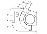
- FIG. 3 is an enlarged view of a main part of FIG. 2. It is a principal part side view which shows the state by which the damper with which the cable was penetrated was assembled
- A) is a perspective view of a damper accommodating part
- (b) is a top view of a damper accommodating part.
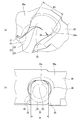
- FIG. 10 is a perspective view of a pretensioner of the seat belt device shown in FIG. 9.
- the seat belt device 10 of the present embodiment is fixed to the outside of the vehicle body of the seat 12, and a retractor portion 14 to which one end side of the seat belt 13 that restrains the occupant 11 to the seat 12 is fixed, A through anchor portion 15 that folds the seat belt 13 near the shoulder of the occupant 11, a lap anchor portion 16 that fixes the other end of the seat belt 13 to the vehicle body, and a seat 12 that is fixed to the inside of the vehicle body and moves to the seat belt 13 And a buckle portion 18 with which a tongue plate 17 that can be supported is engageable.
- FIG. 1 shows a seat belt device 10 arranged on the right seat side, and a seat belt device (not shown) is similarly arranged on the left seat side.
- the front-rear direction, the vertical direction, and the width direction represent directions with respect to the vehicle body when the lap anchor portion 16 is fixed to the vehicle body.
- the front-rear direction is the extension of the cylinder 24. The direction substantially coincides with the direction.
- the lap anchor portion 16 is provided with a pretensioner 19, and the other end portion of the seat belt 13 is attached to the lap anchor 21 and fixed to the vehicle body via the pretensioner 19.
- the retractor unit 14 is also provided with a pretensioner (not shown).
- the pretensioner 19 includes a lap anchor 21, a cable (wire cable) 23, a piston 22, a cylinder 24, a gas generator 25, a housing 30, a nut 26, and a guide. And a damper 40 as a member.
- the cable 23 is connected to the lap anchor 21 at one end, is routed in a substantially U-shaped cable introduction path 31 formed in the housing 30 (see FIG. 4), and is connected to the piston 22 at the other end.
- the cylinder 24 accommodates the other end side of the piston 22 and the cable 23, and arranges the piston 22 in a strokeable and airtight manner. Further, a clutch mechanism (not shown) for preventing the piston 22 from returning after the operation is provided inside the cylinder 24.
- the gas generator 25 supplies high-pressure gas into the cylinder 24 so as to move the piston 22.
- the nut 26 is disposed so that the head portion 26a is located on the outer side of the vehicle body, and the metal cover 28 disposed on the inner side of the vehicle body with respect to the housing 30. 30 is sandwiched.
- a bolt 29 (see FIG. 1) is inserted into the nut 26, and the housing 30 is fixed to the vehicle body or the seat 12 by the bolt 29.
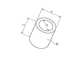
- the damper 40 is a tubular member formed of an elastically deformable resin material or rubber material, and absorbs an impact when the lap anchor 21 is retracted.
- the damper 40 has an inner diameter d slightly larger than the diameter d1 of the cable 23, and guides the inserted cable 23 to be movable.
- the damper 40 is attached to a damper housing portion 32 formed near the cable entrance of the housing 30 in the cable introduction path 31 to support the cable 23.
- the housing 30 is formed by, for example, zinc die casting. Further, one end of the cylinder 24 is connected to the housing 30, and the cable 23 is accommodated in the retractable manner by the damper accommodating portion 32 and the cable introduction path 31 described above.
- the cable introduction path 31 is formed by a groove that is curved in a substantially U shape in a side view so as to continue from the damper housing portion 32, which is near the entrance of the cable 23 to the housing 30, to the cylinder 24.
- the gas generator 25 is mounted, a gas generator mounting portion having a gas insertion path through which gas passes is provided in the housing 30, and the cable introduction path 31 is connected to the cylinder 24 via the gas insertion path. You may communicate with. Further, the gas generator mounting portion may be separated from the housing 30.
- the damper housing portion 32 to which the damper 40 is mounted is formed to be inclined toward the cylinder 24 with respect to the vertical direction when the housing 30 is attached to the vehicle body.
- the cable 23 is attached so as to have an acute angle (about 60 °) with respect to the cylinder 24.
- the angle of the cable 23 of the lap pretensioner does not necessarily have to be an acute angle.
- it may be formed at a substantially right angle (about 90 °) or an obtuse angle (about 115 °).
- the damper housing portion 32 includes an opening 33 that opens on the side surface of the housing 30, and a non-circular hole 34 that is formed continuously from the opening 33, and has a substantially U-shaped cross section. Is formed.
- the opening width W of the opening 33 of the damper housing part 32 is larger than the diameter d1 of the cable 23 and smaller than the outer diameter D of the damper 40. Further, the maximum width W1 of the hole 34 is larger than the opening width W of the opening 33 and smaller than the outer diameter D of the damper 40. Furthermore, the hole 34 is formed in a substantially elliptical shape whose minor axis direction is smaller than the diameter of the damper 40 (see FIG. 6B). Accordingly, the housing 30 is formed with two projecting portions 35 that project inward in the front-rear direction so as to narrow the maximum width W1 of the hole 34 so that the opposing surface in the front-rear direction that defines the opening 33 is narrowed.
- a curved chamfer 36 that gradually increases from the opposite side of the opening 33 in the width direction to the cylinder 24 side is applied to the ridge line portion where the inner wall surface 34a of the hole portion 34 and the upper surface 30a of the housing 30 intersect. Has been.
- the opening portion 33 extends from the inner wall surface 34 a of the hole portion 34.
- the groove part 37 is formed along the direction orthogonal to the extension direction of the cable introduction path 31 and the damper accommodating part 32. Further, the length (depth to the groove portion 37) L of the damper accommodating portion 32 is formed shorter than the length L1 of the damper 40 so that the damper 40 protrudes from the upper surface 30a of the housing 30.
- the cable 23 is bent into a substantially U shape in accordance with the shape of the cable introduction path 31, and is assembled to the cable introduction path 31 and the damper housing portion 32 from the side of the housing 30. Further, the damper 40 through which the cable 23 is inserted is moved downward along the cable 23 and is inserted while being press-fitted into the hole 34 while being guided by a chamfer 36 provided on the upper surface 30 a of the housing 30.
- the assembled cable 23 is pressed against the inner wall surface 34a of the hole 34 (the left inner wall surface in FIG. 6B) by a restoring force that the cable 23 tries to return to a straight line. Further, the cable 23 pressed against the left inner surface is prevented from coming out in the direction of the opening 33 by the projection 35, and the damper 40 can be easily assembled.
- the damper 40 press-fitted into the damper accommodating portion 32 is pressed into the non-circular hole 34 so as to protrude toward the opening 33 and elastically deform into a substantially triangular cross section. Further, when the lower end portion of the damper 40 reaches the bottom portion (groove portion 37) of the damper housing portion 32, the lower end portion of the compressed damper 40 expands in the groove portion 37 to form a bulging portion 40a. Thereby, the bulging part 40a of the damper 40 is locked by the groove part 37, and the damper 40 is mounted in a state in which the damper 40 is prevented from coming off from the damper accommodating part 32.
- the gas generator 25 is activated when the vehicle collides, high pressure gas is sent into the cylinder 24, and the piston 22 strokes within the cylinder 24. Thereby, the cable 23 connected to the piston 22 pulls the lap anchor 21, and the slack of the seat belt 13 corresponding to the movement of the piston 22 is removed, so that the occupant 11 can be restrained and protected quickly.
- the lap anchor 21 drawn by the cable 23 abuts against the damper 40 protruding from the upper surface 30a of the housing 30 and elastically deforms the damper 40, thereby absorbing the impact energy when the lap anchor 21 is drawn.
- the pretensioner 19 when the pretensioner 19 is not operated normally, even if the cable 23 is greatly bent in the vicinity of the damper housing portion 32 due to the movement of the occupant 11, the direct contact between the cable 23 and the housing 30 (damper housing portion 32) is prevented. 40, and the cable 23 is deformed along the chamfer 36 via the damper 40, so that the cable 23 is prevented from being damaged.
- the inclination of the cable 23 due to the movement of the occupant 11 is basically the vehicle body inner side direction opposite to the nut 26, and the opening width to the outside of the opening 33 is the head 26 a of the nut 26. Therefore, the cable 23 does not come out of the damper accommodating portion 32.
- the length L1 of the damper 40 can be set to the minimum length necessary to absorb the impact energy when the lap anchor 21 is retracted.
- the head portion 26a of the nut 26 is disposed outside the vehicle body with respect to the housing 30, and the metal cover 28 is disposed inside the vehicle body.
- the head portion 26 a of the nut 26 is disposed outside the vehicle body with respect to the housing 30, and the metal cover 28 is disposed inside the vehicle body.
- the opening 33 of the damper accommodating portion 32 is completely closed by the metal cover 28. That is, the common housing 30 is used by the lap anchor part 16 of the right seat side and the left seat side.
- the cable 23 In the lap anchor portion 16 on the left seat side, the cable 23 easily tilts in the direction of coming out of the damper accommodating portion 32 due to the movement of the occupant 11, but is regulated by the projection 35 and the opening 33 is blocked by the metal cover 28. Therefore, the cable 23 does not come out of the damper accommodating portion 32.
- the pretensioner 19 includes the cable 23 having one end connected to the lap anchor 21 and the housing 30 that accommodates the cable 23 so as to be retractable.
- the housing 30 includes a cable introduction path 31 that guides the cable 23 into the housing 30, and a damper 40 that is installed in the cable introduction path 31 and guides the cable 23.
- the damper 40 is attached to the cable introduction path 31, the cable introduction path 31 is provided with a groove portion 37 in which at least a part of the damper 40 can be elastically deformed and can enter. Therefore, even if the cable 23 is bent in the cable introduction path 31 due to the movement of the occupant 11, the damper 40 is prevented from coming out of the housing 30.
- the damper 40 can be made to the minimum required length while ensuring the function of absorbing shock energy when the pretensioner is actuated by the damper 40 and the function of protecting the cable when the cable 23 is greatly bent. Without use, the damper 40 can be made shorter than the conventional one.
- the damper 40 since the damper 40 is installed in the vicinity of the cable entrance of the housing 30 in the cable introduction path 31, the wrap anchor 21 drawn by the cable 23 is made to protrude by the damper 40 protruding from the upper surface 30 a of the housing 30.
- the damper 40 is elastically deformed in contact with 40, the impact energy when the lap anchor 21 is retracted can be absorbed. Therefore, the damper 40 is also a protective member that can avoid contact between the lap anchor 21 and the housing 30 when the lap anchor 21 is retracted.
- the groove portion 37 is formed on the wall surface of the cable introduction path 31 and is formed at a position corresponding to the vicinity of the lower end portion of the damper 40, that is, at the lower end portion of the damper housing portion 32.
- the bulging portion 40 a formed on the damper 40 can be engaged with the groove portion 37 by simply press-fitting into the damper 32, and the damper 40 can be easily attached to the damper accommodating portion 32.
- the damper 40 is formed of an elastically deformable resin material or rubber material, and is annular when not attached, and the damper accommodating portion 32 of the cable introduction path 31 is formed in a non-circular shape, so that the force can be reduced with a small force.
- the damper 40 can be assembled by being pressed into the damper accommodating portion 32 of the cable introduction path 31 while deforming the damper 40.
- the damper accommodating portion 32 of the cable introduction path 31 is mounted on the damper accommodation portion 32 of the cable introduction path 31 because the opening width W of the opening 33 opening in the vehicle width direction is smaller than the outer diameter D of the damper 40. It is possible to reliably prevent the released damper 40 from coming off.
- the damper accommodating portion 32 is formed by the non-circular hole portion 34 and the opening portion 33.
- the damper 40 is press-fitted and accommodated so that a part of the damper 40 enters the groove portion 37.
- the shape of the hole 34 and the opening 33 can be deformed, and may be an ellipse, a narrow opening (rounded corners), or a substantially triangular shape.
- damper accommodating part 32 is formed non-circularly in the cable introduction path 31 of the said embodiment, this invention is not restricted to this, If it is the structure into which a guide member is elastically deformed and press-fit, it will be circular. It may be.
- the pretensioner 19 is described as being disposed on the lap anchor portion 16.
- the present invention is not limited to this, and the pretensioner 19 a is configured to be connected to one end of the cable 23 as shown in FIGS. 9 and 10.
- the portion may be provided in the buckle portion 18 connected to the buckle.
- the pretensioners 19 and 19 a may be provided in both the lap anchor portion 16 and the buckle portion 18.
- the pretensioner 19 when the pretensioner 19 is arrange
- the present invention is not limited thereto, and one end of the cable 23 may be connected to the lap anchor 21 or the buckle portion 18 via another member such as an anchor plate or a buckle stay (both not shown).
- the common housing 30 is used for the lap anchor portion 16 (buckle anchor portion) on the right seat side and the left seat side.
- the present invention can be applied even if it is made.
- the present invention is based on a Japanese patent application (Japanese Patent Application No. 2015-106040) filed on May 26, 2015, the contents of which are incorporated herein by reference.
Landscapes
- Engineering & Computer Science (AREA)
- Mechanical Engineering (AREA)
- Automotive Seat Belt Assembly (AREA)
Abstract
L'invention concerne un dispositif de ceinture de sécurité conçu de sorte qu'un élément de guidage présente une longueur minimale requise et de sorte que la dislocation de l'élément de guidage à partir d'un boîtier puisse être empêchée. Un prétendeur (19) est doté d'un boîtier (30) destiné à recevoir un câble (23) de sorte que le câble (23) puisse être tiré dans le boîtier (30), le câble (23) comprenant une extrémité raccordée à un dispositif d'ancrage sous-abdominal (21). Le boîtier (30) comprend: un passage d'introduction de câble (31) permettant d'introduire le câble (23) dans le boîtier (30); et un amortisseur (40) installé dans le passage d'introduction de câble (31) et guidant le câble (23). Le passage d'introduction de câble (31) est doté d'une rainure (37) dans laquelle, pendant le montage de l'amortisseur (40) dans le passage d'introduction de câble (31), au moins une partie de l'amortisseur (40) peut s'adapter tout en étant élastiquement déformée.
Priority Applications (1)
| Application Number | Priority Date | Filing Date | Title |
|---|---|---|---|
| JP2017520583A JP6420474B2 (ja) | 2015-05-26 | 2016-04-27 | シートベルト装置 |
Applications Claiming Priority (2)
| Application Number | Priority Date | Filing Date | Title |
|---|---|---|---|
| JP2015106040 | 2015-05-26 | ||
| JP2015-106040 | 2015-05-26 |
Publications (1)
| Publication Number | Publication Date |
|---|---|
| WO2016190046A1 true WO2016190046A1 (fr) | 2016-12-01 |
Family
ID=57394015
Family Applications (1)
| Application Number | Title | Priority Date | Filing Date |
|---|---|---|---|
| PCT/JP2016/063266 Ceased WO2016190046A1 (fr) | 2015-05-26 | 2016-04-27 | Dispositif de ceinture de sécurité |
Country Status (2)
| Country | Link |
|---|---|
| JP (1) | JP6420474B2 (fr) |
| WO (1) | WO2016190046A1 (fr) |
Cited By (2)
| Publication number | Priority date | Publication date | Assignee | Title |
|---|---|---|---|---|
| CN114981130A (zh) * | 2020-02-07 | 2022-08-30 | 奥托立夫开发公司 | 用于安全带部件的收紧装置 |
| EP4277813A1 (fr) * | 2021-01-12 | 2023-11-22 | Autoliv Development AB | Appareil de tension pour un élément de ceinture de sécurité |
Citations (3)
| Publication number | Priority date | Publication date | Assignee | Title |
|---|---|---|---|---|
| JP2003054360A (ja) * | 2001-06-06 | 2003-02-26 | Takata Corp | シートベルト装置 |
| JP2005225476A (ja) * | 2004-01-14 | 2005-08-25 | Takata Corp | シートベルト装置 |
| JP2008095765A (ja) * | 2006-10-10 | 2008-04-24 | Toyox Co Ltd | ホース継手 |
Family Cites Families (3)
| Publication number | Priority date | Publication date | Assignee | Title |
|---|---|---|---|---|
| JPH11170564A (ja) * | 1997-12-15 | 1999-06-29 | Canon Inc | チューブ接合方法 |
| JP2001271980A (ja) * | 2000-03-27 | 2001-10-05 | Piolax Inc | 導電性チューブのコネクタ |
| JP5853091B2 (ja) * | 2014-12-18 | 2016-02-09 | 三田理化工業株式会社 | シリンジ充填装置 |
-
2016
- 2016-04-27 JP JP2017520583A patent/JP6420474B2/ja active Active
- 2016-04-27 WO PCT/JP2016/063266 patent/WO2016190046A1/fr not_active Ceased
Patent Citations (3)
| Publication number | Priority date | Publication date | Assignee | Title |
|---|---|---|---|---|
| JP2003054360A (ja) * | 2001-06-06 | 2003-02-26 | Takata Corp | シートベルト装置 |
| JP2005225476A (ja) * | 2004-01-14 | 2005-08-25 | Takata Corp | シートベルト装置 |
| JP2008095765A (ja) * | 2006-10-10 | 2008-04-24 | Toyox Co Ltd | ホース継手 |
Cited By (5)
| Publication number | Priority date | Publication date | Assignee | Title |
|---|---|---|---|---|
| CN114981130A (zh) * | 2020-02-07 | 2022-08-30 | 奥托立夫开发公司 | 用于安全带部件的收紧装置 |
| EP4277813A1 (fr) * | 2021-01-12 | 2023-11-22 | Autoliv Development AB | Appareil de tension pour un élément de ceinture de sécurité |
| JP2024506128A (ja) * | 2021-01-12 | 2024-02-09 | オートリブ ディベロップメント エービー | 安全ベルト構成要素用の張力デバイス |
| US20240300440A1 (en) * | 2021-01-12 | 2024-09-12 | Autoliv Development Ab | Tensioning device for a safety belt component |
| US12528439B2 (en) * | 2021-01-12 | 2026-01-20 | Autoliv Development Ab | Tensioning device for a safety belt component |
Also Published As
| Publication number | Publication date |
|---|---|
| JP6420474B2 (ja) | 2018-11-07 |
| JPWO2016190046A1 (ja) | 2018-05-10 |
Similar Documents
| Publication | Publication Date | Title |
|---|---|---|
| KR102399622B1 (ko) | 차량의 사이드 에어백 장치 | |
| KR102452467B1 (ko) | 차량용 에어백 | |
| US8132829B2 (en) | Pretensioner | |
| KR102565349B1 (ko) | 차량용 에어백 | |
| KR102651824B1 (ko) | 루프 에어백 장치 | |
| CN101492038B (zh) | 预张紧器和安全带装置 | |
| US4258934A (en) | Seat belt tensioning device | |
| US6340176B1 (en) | Seat restraint tensioner | |
| CN100579834C (zh) | 预张紧器和安全带装置 | |
| KR102332056B1 (ko) | 사이드 에어백 장치 | |
| US7350734B2 (en) | Seat belt pretensioner | |
| JP4981614B2 (ja) | プリテンショナ及びシートベルト装置 | |
| JP5294444B2 (ja) | 車両用シート | |
| CN100450836C (zh) | 安全带装置 | |
| US7631900B2 (en) | Pre-tensioner | |
| JP6420474B2 (ja) | シートベルト装置 | |
| KR101788184B1 (ko) | 프리텐셔너 및 이를 갖춘 안전벨트장치 | |
| US8960724B2 (en) | Controlled pressure release for seatbelt pretensioning devices | |
| KR101382446B1 (ko) | 차량의 프리텐셔너 | |
| EP1513708B1 (fr) | Pre-tensionneur | |
| JP5399183B2 (ja) | プリテンショナ | |
| KR102585755B1 (ko) | 차량용 시트 벨트 안전 장치 | |
| JP2007238030A (ja) | シートベルト装置 | |
| EP1532025B1 (fr) | Pretensionneur | |
| KR102687313B1 (ko) | 차량용 시트의 프리텐셔너 장치 |
Legal Events
| Date | Code | Title | Description |
|---|---|---|---|
| 121 | Ep: the epo has been informed by wipo that ep was designated in this application |
Ref document number: 16799754 Country of ref document: EP Kind code of ref document: A1 |
|
| ENP | Entry into the national phase |
Ref document number: 2017520583 Country of ref document: JP Kind code of ref document: A |
|
| NENP | Non-entry into the national phase |
Ref country code: DE |
|
| 122 | Ep: pct application non-entry in european phase |
Ref document number: 16799754 Country of ref document: EP Kind code of ref document: A1 |