WO2016190198A1 - Structure de montage de capteur de température - Google Patents
Structure de montage de capteur de température Download PDFInfo
- Publication number
- WO2016190198A1 WO2016190198A1 PCT/JP2016/064771 JP2016064771W WO2016190198A1 WO 2016190198 A1 WO2016190198 A1 WO 2016190198A1 JP 2016064771 W JP2016064771 W JP 2016064771W WO 2016190198 A1 WO2016190198 A1 WO 2016190198A1
- Authority
- WO
- WIPO (PCT)
- Prior art keywords
- temperature sensor
- coil
- mounting structure
- insulator
- holder
- Prior art date
- Legal status (The legal status is an assumption and is not a legal conclusion. Google has not performed a legal analysis and makes no representation as to the accuracy of the status listed.)
- Ceased
Links
Images






Classifications
-
- G—PHYSICS
- G01—MEASURING; TESTING
- G01K—MEASURING TEMPERATURE; MEASURING QUANTITY OF HEAT; THERMALLY-SENSITIVE ELEMENTS NOT OTHERWISE PROVIDED FOR
- G01K1/00—Details of thermometers not specially adapted for particular types of thermometer
- G01K1/14—Supports; Fastening devices; Arrangements for mounting thermometers in particular locations
-
- G—PHYSICS
- G01—MEASURING; TESTING
- G01K—MEASURING TEMPERATURE; MEASURING QUANTITY OF HEAT; THERMALLY-SENSITIVE ELEMENTS NOT OTHERWISE PROVIDED FOR
- G01K13/00—Thermometers specially adapted for specific purposes
- G01K13/04—Thermometers specially adapted for specific purposes for measuring temperature of moving solid bodies
- G01K13/08—Thermometers specially adapted for specific purposes for measuring temperature of moving solid bodies in rotary movement
-
- G—PHYSICS
- G01—MEASURING; TESTING
- G01K—MEASURING TEMPERATURE; MEASURING QUANTITY OF HEAT; THERMALLY-SENSITIVE ELEMENTS NOT OTHERWISE PROVIDED FOR
- G01K7/00—Measuring temperature based on the use of electric or magnetic elements directly sensitive to heat ; Power supply therefor, e.g. using thermoelectric elements
-
- H—ELECTRICITY
- H02—GENERATION; CONVERSION OR DISTRIBUTION OF ELECTRIC POWER
- H02K—DYNAMO-ELECTRIC MACHINES
- H02K11/00—Structural association of dynamo-electric machines with electric components or with devices for shielding, monitoring or protection
- H02K11/20—Structural association of dynamo-electric machines with electric components or with devices for shielding, monitoring or protection for measuring, monitoring, testing, protecting or switching
- H02K11/25—Devices for sensing temperature, or actuated thereby
Definitions
- the present invention relates to a temperature sensor mounting structure.
- JP2011-254628A discloses a mounting structure of a U-shaped temperature sensor that clamps a coil from both sides of the coil and measures the temperature of the coil surface.
- the temperature sensor mounting structure of JP2011-254628A sandwiches the coil from both sides of the coil, so that the coil placement space is reduced and the number of turns of the coil is reduced. For this reason, the coil space factor is lowered by the area for inserting the temperature sensor mounting structure on both sides of the coil, and the driving force performance of the motor cannot be improved.
- An object of the present invention is to provide a temperature sensor mounting structure that can increase a coil space factor by improving a coil arrangement space and improve a driving force performance of a motor.
- a temperature sensor mounting structure includes a stator core, a coil wound around the stator core, and a plurality of insulators that ensure insulation between the stator core and the coil. It is the attachment structure of the temperature sensor which attaches the temperature sensor which measures this.
- the temperature sensor mounting structure includes a holder fixing portion that is fixed to the insulator, and a sensor holding portion that is formed integrally with the holder fixing portion and that holds the temperature sensor on the coil end portion of the coil.
- a storage groove for storing the temperature sensor is formed in the sensor holding portion, and a sensor pressing portion for pressing the temperature sensor against the coil end portion is formed at the groove bottom of the storage groove.
- the holder fixing portion is fixed to the insulator, and the sensor pressing portion formed on the bottom of the storage groove presses the temperature sensor against the coil end portion.
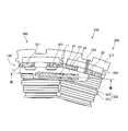
- FIG. 1 is a diagram illustrating a state in which a temperature sensor holder and a temperature sensor according to an embodiment of the present invention are incorporated in a stator.
- FIG. 2 is a schematic configuration diagram of the temperature sensor.
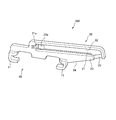
- FIG. 3 is a schematic configuration diagram of a temperature sensor holder according to the embodiment of the present invention.
- FIG. 4A is a diagram showing a state before the temperature sensor holder is assembled into the stator.
- FIG. 4B is a diagram illustrating a state after the temperature sensor holder is incorporated in the stator.
- FIG. 5 is a cross-sectional view taken along the line VV in FIG. 4B, and is a locally enlarged view of a portion where the nail of the temperature sensor holder is located.
- FIG. 6 is a schematic configuration diagram when the temperature sensor is installed in the coil end portion.
- FIG. 7 is a view of the stator incorporating the temperature sensor holder and the temperature sensor from one of the rotor rotation shafts.
- FIG. 8 is a cross-sectional view taken along line VIII-VIII in FIG. 7, and is a schematic configuration diagram of the temperature sensor holder when the temperature sensor is stored.
- FIG. 1 is a view showing a state in which a temperature sensor holder 100 and a temperature sensor 200 according to an embodiment of the present invention are incorporated in a stator 300.
- the temperature sensor holder 100 functions as an attachment structure of the temperature sensor 200 for attaching the temperature sensor 200 to the stator 300.
- the stator 300 is a split core type stator that is divided into a plurality of parts in the circumferential direction of the stator.
- the stator 300 includes a stator core 310, a coil 330 wound around the stator core 310, and an insulator 320 that ensures insulation between the stator core 310 and the coil 330.
- a motor is configured by rotatably incorporating a rotor (not shown) inside the stator 300.
- the stator core 310 is a laminated body made of electromagnetic steel plates.
- the stator core 310 is configured in an annular shape by being connected along the circumferential direction of the stator.
- the insulator 320 is an insulator made of a resin bobbin.
- the insulator 320 is assembled so as to sandwich the stator core 310 from both sides in the rotor rotation axis direction, and ensures electrical insulation between the stator core 310 and the coil 330.
- the insulator 320 assembled to the stator core 310 has two flange portions 321 that are formed to protrude in the rotor rotation axis direction.
- the coil 330 is an electric wire whose outer periphery is covered with an insulating coating material.
- the coil 330 is wound around the stator core 310 via an insulator 320 as shown in FIG.
- the coil 330 includes an in-slot coil portion 331 disposed in a slot that is a space formed by the adjacent stator core 310, and a coil end portion 332 disposed in a position protruding from the slot.
- FIG. 2 is a schematic configuration diagram of the temperature sensor 200.
- the temperature sensor 200 includes a temperature measuring unit 210 that measures the temperature of the coil 330, a harness 220 that secures input / output signals and electric power, and a case 230 that houses the temperature measuring unit 210 and the like. Is done.
- the temperature sensor 200 is used in a state of being attached to a temperature sensor holder 100 described later.
- FIG. 3 is a schematic configuration diagram of the temperature sensor holder 100.
- the temperature sensor holder 100 has a holder fixing part 10 and a sensor holding part 20 formed integrally with the holder fixing part 10.
- the holder fixing portion 10 is provided with two claws 11 that sandwich the flange portion 321 of the insulator 320. As shown in FIGS. 4A and 4B, the holder fixing portion 10 is fixed to the insulator 320 by fitting the claw 11 to the flange portion 321 from the rotor rotation axis direction.
- FIG. 4A is a diagram illustrating a state before the temperature sensor holder 100 is assembled into the stator 300
- FIG. 4B is a diagram illustrating a state after the temperature sensor holder 100 is assembled into the stator 300.
- the temperature sensor holder 100 is positioned and fixed in the rotor rotation axis direction when the end 11a of the claw 11 contacts the position fixing surface 320a of the insulator 320. As shown in FIG. Since the insulator 320 has the position fixing surface 320a, the temperature sensor holder 100 does not hit the coil 330 strongly when the temperature sensor holder 100 is mounted, and the insulating coating material coated on the outer periphery of the coil 330 is prevented from being damaged. For this reason, when assembling the temperature sensor holder 100 to the stator 300, it is not necessary to assemble with great care, and assembling workability is improved.
- FIG. 5 is a cross-sectional view taken along the line VV in FIG. 4B and is a locally enlarged view of a portion where the claw 11 of the temperature sensor holder 100 is located.
- the flange portion 321 of the insulator 320 is provided with a taper 321 a and a step 321 b below the taper 321 a.
- the end portion 11b of the claw 11 is caught by the step 321b of the flange portion 321.
- the end 11b is an end formed on the opposite side of the end 11a of the claw 11 in the rotor rotation axis direction. For this reason, it is difficult for the claw 11 to come off from the flange portion 321, so that the temperature sensor holder 100 can be prevented from being detached from the insulator 320 after the temperature sensor holder 100 is assembled to the stator 300.
- the temperature sensor holder 100 can move slightly in the direction of the rotor rotation axis, but an approximate positioning is possible. Finally, since the temperature sensor 200 is fixed to the coil 330 by varnish application, the position of the temperature sensor holder 100 does not shift due to vibration or the like.
- the sensor holding unit 20 of the temperature sensor holder 100 will be described.
- the sensor holding part 20 has a storage groove 21 and an overhang part 23.
- the storage groove 21 is a groove for storing the temperature sensor 200.
- a sensor pressing portion 22 that presses the temperature sensor 200 against the coil end portion 332 of the coil 330 is formed at the groove bottom of the storage groove 21.
- the sensor pressing portion 22 has a cantilever structure formed so as to extend from one end of the storage groove 21 on the projecting portion 23 side toward the other end of the storage groove 21 on the holder fixing portion 10 side.
- the sensor pressing part 22 has a convex part 22 a that protrudes toward the temperature sensor 200 at the position on the other end side of the storage groove 21.
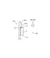
- FIG. 6 is an enlarged schematic configuration diagram of the sensor pressing portion 22 of the temperature sensor holder 100 in a state where the temperature sensor 200 is pressed against the coil end portion 332.
- the sensor pressing portion 22 is held by pressing the temperature measuring portion 210 of the temperature sensor 200 against the coil end portion 332 by the convex portion 22 a formed on the other end side of the storage groove 21.
- a spring force for pressing the temperature measuring part 210 of the temperature sensor 200 against the coil end part 332 acts on the convex part 22a.
- the temperature measuring unit 210 measures the temperature of the outermost surface of the coil 330 by being pressed by the convex portion 22 a and coming into contact with the coil end portion 332. Information on the temperature detected by the temperature measuring unit 210 is output to an external control device (not shown) via the harness 220.
- the holder fixing portion 10 of the temperature sensor holder 100 is repelled by a spring force in the direction of the rotor rotation axis and away from the coil end portion 332. That is, the pawl 11 of the temperature sensor holder 100 is repelled by the spring force in the direction in which the claws 11 come out of the flange portion 321 of the insulator 320. However, as shown in FIG. 5, the end 11 b of the claw 11 is caught by the step 321 b of the flange 321, so that the position of the temperature sensor holder 100 is fixed without being detached from the insulator 320.
- FIG. 7 is a view of the stator 300 incorporating the temperature sensor holder 100 and the temperature sensor 200 from one of the rotor rotation shafts.
- the overhang portion 23 has a structure that protrudes from the holder fixing portion 10 in the circumferential direction of the stator and overhangs on the coil end portion 332 of the adjacently arranged coil 330.
- a part of the storage groove 21 is formed in the overhang portion 23.
- an escape portion 24 and an opening portion 25 are formed on the side of the holder fixing portion 10 on the claw 11 side.
- the escape portion 24 is formed to extend along the flange portion 321 of the insulator 320 disposed adjacent to the insulator 320 on which the temperature sensor holder 100 is installed.
- the temperature sensor holder 100 can be disposed on the coil end portion 332 of the coil 330 without the interference between the overhanging portion 23 and the flange portion 321 of the insulator 320 disposed adjacent to the overhanging portion 23 because the overhanging portion 23 has the escape portion 24. .
- the opening 25 is an opening for taking out the harness 220 of the temperature sensor 200 from above the insulator 320 arranged adjacent to the insulator 320 where the temperature sensor holder 100 is installed.
- the opening 25 is formed so as to be positioned between the two flange portions 321 of the insulator 320 disposed adjacent to each other.
- FIG. 8 is a cross-sectional view taken along line VIII-VIII in FIG. 7, and is a schematic configuration diagram of the temperature sensor holder 100 when the temperature sensor 200 is stored.
- the temperature sensor 200 is inserted into the storage groove 21, as shown in FIG. Since the temperature sensor holder 100 is in contact with the coil 330 that is at a high temperature, the temperature sensor holder 100 is preferably composed of a highly heat-resistant resin or the like.
- the tip of the case 230 of the temperature sensor 200 is aligned with the tip receiving portion 21 a of the storage groove 21 when the temperature sensor 200 is inserted into the storage groove 21 of the temperature sensor holder 100.
- the tip of the case 230 means at least a part farther from the harness 220 than the temperature measuring unit 210.
- the case 230 is formed in a stepped shape whose diameter gradually decreases toward the tip. Since the temperature measuring unit 210 and the harness 220 do not exist at the tip of the case 230, the tip of the case 230 has a smaller diameter than other parts.
- the tip receiving portion 21 a of the storage groove 21 is formed in a hollow shape into which the tip of the case 230 can be inserted.
- the temperature sensor 200 can be accurately aligned by inserting the tip of the case 230 into the tip receiving portion 21a of the storage groove 21. Moreover, since the convex part 22a which presses the temperature sensor 200 is protrudingly formed in the sensor pressing part 22 of the temperature sensor holder 100, even if the case 230 is formed in steps, the convex part 22a is the temperature sensor 200. It contacts the temperature measuring unit 210 of Note that the case 230 may be formed in a tapered shape whose diameter gradually decreases toward the tip.
- the temperature sensor holder 100 which is the temperature sensor mounting structure according to the above-described embodiment, the following effects can be obtained.
- the temperature sensor holder 100 includes a stator core 310, a coil 330 wound around the stator core 310, and an insulator 320 that secures insulation between the stator core 310 and the coil 330.
- This is a temperature sensor mounting structure for mounting a temperature sensor 200 for measuring temperature.
- the temperature sensor holder 100 includes a holder fixing portion 10 fixed to the insulator 320 and a sensor holding portion 20 that is formed integrally with the holder fixing portion 10 and holds the temperature sensor 200 on the coil end portion 332 of the coil 330.
- a storage groove 21 for storing the temperature sensor 200 is formed in the sensor holding portion 20, and a sensor pressing portion 22 that presses the temperature sensor 200 against the coil end portion 332 is formed at the groove bottom of the storage groove 21.
- the holder fixing portion 10 is fixed to the insulator 320, and the sensor pressing portion 22 formed on the groove bottom of the storage groove 21 presses the temperature sensor 200 against the coil end portion 332, so that the coil 330 is It is not necessary to arrange the temperature sensor 200 or the temperature sensor holder 100 in the arrangement space, and the arrangement space for the coil 330 can be secured. As a result, it is not necessary to reduce the number of turns of the coil by the capacity of the temperature sensor 200 or the temperature sensor holder 100, and the coil space factor is increased by increasing the number of turns of the coil, thereby improving the driving force performance of the motor. Can do.
- the sensor pressing portion 22 has a cantilever structure formed so as to extend from one end of the storage groove 21 toward the other end, and presses the temperature sensor 200 on the other end side of the storage groove 21. To do.
- the temperature sensor holder 100 since the sensor pressing portion 22 has a cantilever structure, a spring force that presses the temperature sensor 200 is generated. Moreover, since the holder fixing
- the sensor pressing portion 22 has a convex portion 22 a that protrudes toward the temperature sensor 200 at a position on the other end side of the storage groove 21.
- the temperature measuring unit 210 of the temperature sensor 200 can be pressed by the convex portion 22 a of the sensor pressing unit 22.
- the temperature measuring unit 210 can be reliably pressed against the coil end portion 332 of the coil 330.
- the sensor holding part 20 has an overhang part 23 formed to protrude from the holder fixing part 10 in the stator circumferential direction.
- the stress concentrated on the sensor pressing portion 22 can be reduced.
- the overhang portion 23 has an escape portion 24 that avoids interference with the insulator 320 that is disposed adjacently.
- the length of the sensor pressing portion 22 can be increased so as to extend along the insulator 320 arranged adjacently, the stress concentrated on the sensor pressing portion 22 can be reduced.
- the projecting portion 23 has an opening 25 for taking out the harness 220 of the temperature sensor 200 from the insulator 320 disposed adjacently.
- the harness 220 of the temperature sensor 200 stored in the storage groove 21 is positioned on the coil end portion 332 of the coil 330 disposed adjacently. For this reason, the length of the harness 220 can be shortened by forming the opening 25 in the temperature sensor holder 100 so that the harness 220 is taken out from the insulator 320 arranged adjacently, and the wiring is simplified. Can do.
- the sensor pressing portion 22 has a cantilever structure, but may have a cantilever structure that is held by both ends of the storage groove 21.
- the temperature sensor 200 can be pressed against the coil end portion 332.
- the stator is not limited to the above-described split core type stator, and may be an integral core type stator. Further, FIG. 1 shows a state where only one temperature sensor holder 100 into which the temperature sensor 200 is inserted is attached to the stator, but a plurality of temperature sensor holders 100 can be attached to the stator.
Landscapes
- Engineering & Computer Science (AREA)
- Physics & Mathematics (AREA)
- General Physics & Mathematics (AREA)
- Microelectronics & Electronic Packaging (AREA)
- Power Engineering (AREA)
- Measuring Temperature Or Quantity Of Heat (AREA)
Abstract
Priority Applications (5)
| Application Number | Priority Date | Filing Date | Title |
|---|---|---|---|
| JP2017520655A JP6484334B2 (ja) | 2015-05-25 | 2016-05-18 | 温度センサホルダ |
| KR1020177035881A KR101989265B1 (ko) | 2015-05-25 | 2016-05-18 | 온도 센서 홀더 |
| US15/576,420 US10690549B2 (en) | 2015-05-25 | 2016-05-18 | Temperature sensor holder |
| EP16799904.4A EP3306291B1 (fr) | 2015-05-25 | 2016-05-18 | Structure de montage de capteur de température |
| CN201680029131.XA CN107615026B (zh) | 2015-05-25 | 2016-05-18 | 温度传感器支架 |
Applications Claiming Priority (2)
| Application Number | Priority Date | Filing Date | Title |
|---|---|---|---|
| JP2015-105571 | 2015-05-25 | ||
| JP2015105571 | 2015-05-25 |
Publications (1)
| Publication Number | Publication Date |
|---|---|
| WO2016190198A1 true WO2016190198A1 (fr) | 2016-12-01 |
Family
ID=57393389
Family Applications (1)
| Application Number | Title | Priority Date | Filing Date |
|---|---|---|---|
| PCT/JP2016/064771 Ceased WO2016190198A1 (fr) | 2015-05-25 | 2016-05-18 | Structure de montage de capteur de température |
Country Status (6)
| Country | Link |
|---|---|
| US (1) | US10690549B2 (fr) |
| EP (1) | EP3306291B1 (fr) |
| JP (1) | JP6484334B2 (fr) |
| KR (1) | KR101989265B1 (fr) |
| CN (1) | CN107615026B (fr) |
| WO (1) | WO2016190198A1 (fr) |
Cited By (11)
| Publication number | Priority date | Publication date | Assignee | Title |
|---|---|---|---|---|
| CN108885142A (zh) * | 2017-03-16 | 2018-11-23 | 株式会社芝浦电子 | 温度传感器 |
| WO2019087568A1 (fr) * | 2017-11-02 | 2019-05-09 | 日立オートモティブシステムズ株式会社 | Stator de machine électrique tournante et machine électrique tournante |
| DE102018211089A1 (de) * | 2018-07-05 | 2020-01-09 | Volkswagen Aktiengesellschaft | Sensorvorrichtung, Elektromaschinensystem und Kraftfahrzeug |
| JP2020020685A (ja) * | 2018-08-01 | 2020-02-06 | 本田技研工業株式会社 | 温度センサの取付構造 |
| US10886822B2 (en) | 2018-03-07 | 2021-01-05 | Vitesco Technologies GmbH | Isolation ring for isolating end windings of a starter generator for a hybrid electric vehicle |
| CN113364221A (zh) * | 2021-06-23 | 2021-09-07 | 珠海格力电器股份有限公司 | 一种电机转子温度检测系统及包括其的电机 |
| JP2021165806A (ja) * | 2020-04-08 | 2021-10-14 | 沖電気工業株式会社 | 温度検出装置及び画像形成装置 |
| JP2021182801A (ja) * | 2020-05-18 | 2021-11-25 | トヨタ自動車株式会社 | 車両用回転電機のステータ |
| JP2022524009A (ja) * | 2019-03-05 | 2022-04-27 | ツェットエフ、フリードリッヒスハーフェン、アクチエンゲゼルシャフト | ステータのための相互接続装置、温度センサデバイス、および温度を検出するシステム |
| US11502582B2 (en) | 2017-12-13 | 2022-11-15 | Vitesco Technologies GmbH | Spring clamp for fitting onto an electrical conductor of an electric machine |
| WO2023053344A1 (fr) * | 2021-09-30 | 2023-04-06 | 本田技研工業株式会社 | Pièce de montage de thermistor, et structure de stator |
Families Citing this family (13)
| Publication number | Priority date | Publication date | Assignee | Title |
|---|---|---|---|---|
| KR20030082763A (ko) * | 2002-04-18 | 2003-10-23 | 에스케이케미칼주식회사 | 관절조직 보호 작용을 갖는 생약조성물 |
| DE102018116889A1 (de) * | 2018-07-12 | 2020-01-16 | Schaeffler Technologies AG & Co. KG | Anordnung zur Temperaturerfassung einer Statorwicklung einer elektrischen Maschine |
| DE102018131973A1 (de) * | 2018-12-12 | 2020-06-18 | Thyssenkrupp Ag | Stator und elektrische Maschine |
| DE102019204002A1 (de) * | 2019-03-25 | 2020-10-01 | Audi Ag | Verfahren zum Herstellen eines Bauteils |
| CN110470410B (zh) * | 2019-09-24 | 2020-12-22 | 佛山顺德谷登厨具设备有限公司 | 一种热敏传感器 |
| US12034343B2 (en) * | 2019-10-10 | 2024-07-09 | Shibaura Electronics Co. Ltd. | Temperature sensor and electric motor |
| CN111157129B (zh) * | 2020-02-18 | 2022-09-06 | 佛山市顺德区伊戈尔电力科技有限公司 | 温度测量装置及所应用的电线圈组件 |
| KR102832208B1 (ko) * | 2020-07-23 | 2025-07-10 | 현대모비스 주식회사 | 모터용 버스바 유닛 |
| DE102020126632B4 (de) | 2020-10-12 | 2022-11-17 | Schaeffler Technologies AG & Co. KG | Anbindung eines Temperatursensors an einen Verschaltungsring einer elektrischen Maschine |
| JP7036245B1 (ja) * | 2021-02-05 | 2022-03-15 | 三菱電機株式会社 | インシュレータ及び固定子 |
| US12203812B2 (en) | 2021-03-01 | 2025-01-21 | Copeland Cold Chain Lp | Bracket for temperature sensor |
| JP7716577B2 (ja) | 2022-03-29 | 2025-07-31 | 本田技研工業株式会社 | 温度センサホルダおよび温度センサ取付方法 |
| JP7310037B1 (ja) * | 2022-06-07 | 2023-07-18 | 株式会社芝浦電子 | 温度センサおよび回転電機 |
Citations (4)
| Publication number | Priority date | Publication date | Assignee | Title |
|---|---|---|---|---|
| JP2010071708A (ja) * | 2008-09-17 | 2010-04-02 | Piolax Inc | 温度センサの取付構造 |
| JP2012217303A (ja) * | 2011-04-01 | 2012-11-08 | Honda Motor Co Ltd | 車両用駆動装置 |
| JP2013172478A (ja) * | 2012-02-17 | 2013-09-02 | Nifco Inc | インシュレータ及びステータ |
| JP5726277B1 (ja) * | 2013-11-29 | 2015-05-27 | 三菱電機株式会社 | 回転電機、回転電機の固定子、及び回転電機の固定子の製造方法 |
Family Cites Families (10)
| Publication number | Priority date | Publication date | Assignee | Title |
|---|---|---|---|---|
| US4313069A (en) * | 1980-02-26 | 1982-01-26 | Westinghouse Electric Corp. | Mounting for thermal protector used in dynamoelectric machine stator windings |
| JP2010252508A (ja) * | 2009-04-15 | 2010-11-04 | Nissan Motor Co Ltd | 温度検出素子の取付構造 |
| JP5609275B2 (ja) * | 2010-06-02 | 2014-10-22 | 日産自動車株式会社 | 温度センサの取り付け構造および温度センサの取り付け方法 |
| JP5720185B2 (ja) * | 2010-11-04 | 2015-05-20 | アイシン精機株式会社 | 電動モータおよびその電動モータを用いた車両用駆動装置 |
| JP5605171B2 (ja) * | 2010-11-04 | 2014-10-15 | アイシン精機株式会社 | 電動モータおよびその電動モータを用いた車両用駆動装置 |
| JP5672984B2 (ja) * | 2010-11-04 | 2015-02-18 | アイシン精機株式会社 | 回転電機のステータ |
| JP2013158078A (ja) * | 2012-01-27 | 2013-08-15 | Honda Motor Co Ltd | 回転電機のステータ |
| JP5971125B2 (ja) * | 2013-01-09 | 2016-08-17 | 株式会社デンソー | 固定子及びそれを備えた回転電機 |
| EP3252447B1 (fr) * | 2015-01-29 | 2019-07-17 | Shibaura Electronics Co., Ltd. | Capteur de température |
| JP5986245B2 (ja) * | 2015-03-03 | 2016-09-06 | ファナック株式会社 | 温度検出素子を固定する固定具、電動機、および、温度検出素子の固定方法 |
-
2016
- 2016-05-18 CN CN201680029131.XA patent/CN107615026B/zh active Active
- 2016-05-18 US US15/576,420 patent/US10690549B2/en active Active
- 2016-05-18 JP JP2017520655A patent/JP6484334B2/ja active Active
- 2016-05-18 EP EP16799904.4A patent/EP3306291B1/fr active Active
- 2016-05-18 WO PCT/JP2016/064771 patent/WO2016190198A1/fr not_active Ceased
- 2016-05-18 KR KR1020177035881A patent/KR101989265B1/ko not_active Expired - Fee Related
Patent Citations (4)
| Publication number | Priority date | Publication date | Assignee | Title |
|---|---|---|---|---|
| JP2010071708A (ja) * | 2008-09-17 | 2010-04-02 | Piolax Inc | 温度センサの取付構造 |
| JP2012217303A (ja) * | 2011-04-01 | 2012-11-08 | Honda Motor Co Ltd | 車両用駆動装置 |
| JP2013172478A (ja) * | 2012-02-17 | 2013-09-02 | Nifco Inc | インシュレータ及びステータ |
| JP5726277B1 (ja) * | 2013-11-29 | 2015-05-27 | 三菱電機株式会社 | 回転電機、回転電機の固定子、及び回転電機の固定子の製造方法 |
Non-Patent Citations (1)
| Title |
|---|
| See also references of EP3306291A4 * |
Cited By (23)
| Publication number | Priority date | Publication date | Assignee | Title |
|---|---|---|---|---|
| EP3401658A4 (fr) * | 2017-03-16 | 2019-01-02 | Shibaura Electronics Co., Ltd. | Capteur de température |
| CN108885142B (zh) * | 2017-03-16 | 2019-11-26 | 株式会社芝浦电子 | 温度传感器 |
| US10935434B2 (en) | 2017-03-16 | 2021-03-02 | Shibaura Electronics Co., Ltd. | Temperature sensor |
| CN108885142A (zh) * | 2017-03-16 | 2018-11-23 | 株式会社芝浦电子 | 温度传感器 |
| CN111279593B (zh) * | 2017-11-02 | 2022-06-10 | 日立安斯泰莫株式会社 | 旋转电机的定子及旋转电机 |
| WO2019087568A1 (fr) * | 2017-11-02 | 2019-05-09 | 日立オートモティブシステムズ株式会社 | Stator de machine électrique tournante et machine électrique tournante |
| US11411473B2 (en) | 2017-11-02 | 2022-08-09 | Hitachi Astemo, Ltd. | Stator for rotating electric machine and rotating electric machine |
| CN111279593A (zh) * | 2017-11-02 | 2020-06-12 | 日立汽车系统株式会社 | 旋转电机的定子及旋转电机 |
| JPWO2019087568A1 (ja) * | 2017-11-02 | 2020-10-01 | 日立オートモティブシステムズ株式会社 | 回転電機の固定子、及び、回転電機 |
| US11502582B2 (en) | 2017-12-13 | 2022-11-15 | Vitesco Technologies GmbH | Spring clamp for fitting onto an electrical conductor of an electric machine |
| US10886822B2 (en) | 2018-03-07 | 2021-01-05 | Vitesco Technologies GmbH | Isolation ring for isolating end windings of a starter generator for a hybrid electric vehicle |
| DE102018211089A1 (de) * | 2018-07-05 | 2020-01-09 | Volkswagen Aktiengesellschaft | Sensorvorrichtung, Elektromaschinensystem und Kraftfahrzeug |
| JP2020020685A (ja) * | 2018-08-01 | 2020-02-06 | 本田技研工業株式会社 | 温度センサの取付構造 |
| JP2022524009A (ja) * | 2019-03-05 | 2022-04-27 | ツェットエフ、フリードリッヒスハーフェン、アクチエンゲゼルシャフト | ステータのための相互接続装置、温度センサデバイス、および温度を検出するシステム |
| JP7538810B2 (ja) | 2019-03-05 | 2024-08-22 | ツェットエフ、フリードリッヒスハーフェン、アクチエンゲゼルシャフト | ステータのための相互接続装置、温度センサデバイス、および温度を検出するシステム |
| JP2021165806A (ja) * | 2020-04-08 | 2021-10-14 | 沖電気工業株式会社 | 温度検出装置及び画像形成装置 |
| JP2021182801A (ja) * | 2020-05-18 | 2021-11-25 | トヨタ自動車株式会社 | 車両用回転電機のステータ |
| JP7471038B2 (ja) | 2020-05-18 | 2024-04-19 | トヨタ自動車株式会社 | 車両用回転電機のステータ |
| CN113364221A (zh) * | 2021-06-23 | 2021-09-07 | 珠海格力电器股份有限公司 | 一种电机转子温度检测系统及包括其的电机 |
| CN113364221B (zh) * | 2021-06-23 | 2022-07-26 | 珠海格力电器股份有限公司 | 一种电机转子温度检测系统及包括其的电机 |
| JPWO2023053344A1 (fr) * | 2021-09-30 | 2023-04-06 | ||
| WO2023053344A1 (fr) * | 2021-09-30 | 2023-04-06 | 本田技研工業株式会社 | Pièce de montage de thermistor, et structure de stator |
| JP7555497B2 (ja) | 2021-09-30 | 2024-09-24 | 本田技研工業株式会社 | サーミスタステー、およびステータ構造 |
Also Published As
| Publication number | Publication date |
|---|---|
| US20180156669A1 (en) | 2018-06-07 |
| JP6484334B2 (ja) | 2019-03-20 |
| US10690549B2 (en) | 2020-06-23 |
| CN107615026B (zh) | 2019-11-26 |
| KR101989265B1 (ko) | 2019-06-13 |
| JPWO2016190198A1 (ja) | 2018-03-01 |
| EP3306291B1 (fr) | 2020-07-08 |
| EP3306291A4 (fr) | 2018-06-20 |
| KR20180008607A (ko) | 2018-01-24 |
| EP3306291A1 (fr) | 2018-04-11 |
| CN107615026A (zh) | 2018-01-19 |
Similar Documents
| Publication | Publication Date | Title |
|---|---|---|
| JP6484334B2 (ja) | 温度センサホルダ | |
| CN105900318B (zh) | 磁体式发电机 | |
| JP6093673B2 (ja) | レゾルバ | |
| JP6519241B2 (ja) | 直流モータ | |
| EP3706293A1 (fr) | Moteur | |
| JP4735691B2 (ja) | モータの製造方法 | |
| CN103825377B (zh) | 定子 | |
| CN109417336B (zh) | 旋转电机的定子构造、以及旋转电机的定子构造的组装方法 | |
| JP2013051825A (ja) | Vr型レゾルバ | |
| JP2016525338A (ja) | 電気機械 | |
| KR20140099208A (ko) | 보빈 및 회전 전기 기기 | |
| JP2011200007A (ja) | レゾルバのステータ構造 | |
| JP6246416B2 (ja) | 回転電機 | |
| WO2013111868A1 (fr) | Câble électrique | |
| WO2019097992A1 (fr) | Machine électrique rotative | |
| EP2874283B1 (fr) | Structure de maintien de borne provisoire, et résolveur comprenant une structure de maintien de borne provisoire | |
| JP5541597B2 (ja) | 太陽電池モジュール用端子ボックスの出力ケーブル固定構造 | |
| JP2013247801A (ja) | 電機子と電機子の製造方法 | |
| JP2019068595A (ja) | ステータ構造およびレゾルバ | |
| JP5852513B2 (ja) | モータ | |
| JP6585395B2 (ja) | 給電リング及び給電リングの製造方法 | |
| JP7251734B2 (ja) | レゾルバのステータ巻線の端線固定構造 | |
| US11682952B2 (en) | Method for producing a wire coil, corresponding wire coil, and method for producing an electrical machine | |
| JP5144180B2 (ja) | ステータの中点連結構造 | |
| KR20180067821A (ko) | 친환경차량용 구동 모터 |
Legal Events
| Date | Code | Title | Description |
|---|---|---|---|
| 121 | Ep: the epo has been informed by wipo that ep was designated in this application |
Ref document number: 16799904 Country of ref document: EP Kind code of ref document: A1 |
|
| ENP | Entry into the national phase |
Ref document number: 2017520655 Country of ref document: JP Kind code of ref document: A |
|
| WWE | Wipo information: entry into national phase |
Ref document number: 15576420 Country of ref document: US |
|
| NENP | Non-entry into the national phase |
Ref country code: DE |
|
| ENP | Entry into the national phase |
Ref document number: 20177035881 Country of ref document: KR Kind code of ref document: A |
|
| WWE | Wipo information: entry into national phase |
Ref document number: 2016799904 Country of ref document: EP |