WO2016190385A1 - ボールジョイント - Google Patents
ボールジョイント Download PDFInfo
- Publication number
- WO2016190385A1 WO2016190385A1 PCT/JP2016/065566 JP2016065566W WO2016190385A1 WO 2016190385 A1 WO2016190385 A1 WO 2016190385A1 JP 2016065566 W JP2016065566 W JP 2016065566W WO 2016190385 A1 WO2016190385 A1 WO 2016190385A1
- Authority
- WO
- WIPO (PCT)
- Prior art keywords
- ball joint
- dust cover
- ball
- shaft
- attached
- Prior art date
- Legal status (The legal status is an assumption and is not a legal conclusion. Google has not performed a legal analysis and makes no representation as to the accuracy of the status listed.)
- Ceased
Links
Images



Classifications
-
- F—MECHANICAL ENGINEERING; LIGHTING; HEATING; WEAPONS; BLASTING
- F16—ENGINEERING ELEMENTS AND UNITS; GENERAL MEASURES FOR PRODUCING AND MAINTAINING EFFECTIVE FUNCTIONING OF MACHINES OR INSTALLATIONS; THERMAL INSULATION IN GENERAL
- F16C—SHAFTS; FLEXIBLE SHAFTS; ELEMENTS OR CRANKSHAFT MECHANISMS; ROTARY BODIES OTHER THAN GEARING ELEMENTS; BEARINGS
- F16C11/00—Pivots; Pivotal connections
- F16C11/04—Pivotal connections
- F16C11/06—Ball-joints; Other joints having more than one degree of angular freedom, i.e. universal joints
- F16C11/0666—Sealing means between the socket and the inner member shaft
- F16C11/0671—Sealing means between the socket and the inner member shaft allowing operative relative movement of joint parts due to flexing of the sealing means
-
- F—MECHANICAL ENGINEERING; LIGHTING; HEATING; WEAPONS; BLASTING
- F16—ENGINEERING ELEMENTS AND UNITS; GENERAL MEASURES FOR PRODUCING AND MAINTAINING EFFECTIVE FUNCTIONING OF MACHINES OR INSTALLATIONS; THERMAL INSULATION IN GENERAL
- F16C—SHAFTS; FLEXIBLE SHAFTS; ELEMENTS OR CRANKSHAFT MECHANISMS; ROTARY BODIES OTHER THAN GEARING ELEMENTS; BEARINGS
- F16C11/00—Pivots; Pivotal connections
- F16C11/04—Pivotal connections
- F16C11/06—Ball-joints; Other joints having more than one degree of angular freedom, i.e. universal joints
-
- F—MECHANICAL ENGINEERING; LIGHTING; HEATING; WEAPONS; BLASTING
- F16—ENGINEERING ELEMENTS AND UNITS; GENERAL MEASURES FOR PRODUCING AND MAINTAINING EFFECTIVE FUNCTIONING OF MACHINES OR INSTALLATIONS; THERMAL INSULATION IN GENERAL
- F16C—SHAFTS; FLEXIBLE SHAFTS; ELEMENTS OR CRANKSHAFT MECHANISMS; ROTARY BODIES OTHER THAN GEARING ELEMENTS; BEARINGS
- F16C11/00—Pivots; Pivotal connections
- F16C11/04—Pivotal connections
- F16C11/06—Ball-joints; Other joints having more than one degree of angular freedom, i.e. universal joints
- F16C11/0695—Mounting of ball-joints, e.g. fixing them to a connecting rod
-
- F—MECHANICAL ENGINEERING; LIGHTING; HEATING; WEAPONS; BLASTING
- F16—ENGINEERING ELEMENTS AND UNITS; GENERAL MEASURES FOR PRODUCING AND MAINTAINING EFFECTIVE FUNCTIONING OF MACHINES OR INSTALLATIONS; THERMAL INSULATION IN GENERAL
- F16C—SHAFTS; FLEXIBLE SHAFTS; ELEMENTS OR CRANKSHAFT MECHANISMS; ROTARY BODIES OTHER THAN GEARING ELEMENTS; BEARINGS
- F16C41/00—Other accessories, e.g. devices integrated in the bearing not relating to the bearing function as such
- F16C41/04—Preventing damage to bearings during storage or transport thereof or when otherwise out of use
-
- F—MECHANICAL ENGINEERING; LIGHTING; HEATING; WEAPONS; BLASTING
- F16—ENGINEERING ELEMENTS AND UNITS; GENERAL MEASURES FOR PRODUCING AND MAINTAINING EFFECTIVE FUNCTIONING OF MACHINES OR INSTALLATIONS; THERMAL INSULATION IN GENERAL
- F16J—PISTONS; CYLINDERS; SEALINGS
- F16J15/00—Sealings
- F16J15/50—Sealings between relatively-movable members, by means of a sealing without relatively-moving surfaces, e.g. fluid-tight sealings for transmitting motion through a wall
- F16J15/52—Sealings between relatively-movable members, by means of a sealing without relatively-moving surfaces, e.g. fluid-tight sealings for transmitting motion through a wall by means of sealing bellows or diaphragms
-
- F—MECHANICAL ENGINEERING; LIGHTING; HEATING; WEAPONS; BLASTING
- F16—ENGINEERING ELEMENTS AND UNITS; GENERAL MEASURES FOR PRODUCING AND MAINTAINING EFFECTIVE FUNCTIONING OF MACHINES OR INSTALLATIONS; THERMAL INSULATION IN GENERAL
- F16J—PISTONS; CYLINDERS; SEALINGS
- F16J3/00—Diaphragms; Bellows; Bellows pistons
- F16J3/04—Bellows
-
- F—MECHANICAL ENGINEERING; LIGHTING; HEATING; WEAPONS; BLASTING
- F16—ENGINEERING ELEMENTS AND UNITS; GENERAL MEASURES FOR PRODUCING AND MAINTAINING EFFECTIVE FUNCTIONING OF MACHINES OR INSTALLATIONS; THERMAL INSULATION IN GENERAL
- F16J—PISTONS; CYLINDERS; SEALINGS
- F16J3/00—Diaphragms; Bellows; Bellows pistons
- F16J3/04—Bellows
- F16J3/041—Non-metallic bellows
- F16J3/042—Fastening details
-
- F—MECHANICAL ENGINEERING; LIGHTING; HEATING; WEAPONS; BLASTING
- F16—ENGINEERING ELEMENTS AND UNITS; GENERAL MEASURES FOR PRODUCING AND MAINTAINING EFFECTIVE FUNCTIONING OF MACHINES OR INSTALLATIONS; THERMAL INSULATION IN GENERAL
- F16J—PISTONS; CYLINDERS; SEALINGS
- F16J3/00—Diaphragms; Bellows; Bellows pistons
- F16J3/04—Bellows
- F16J3/048—Bellows with guiding or supporting means
-
- Y—GENERAL TAGGING OF NEW TECHNOLOGICAL DEVELOPMENTS; GENERAL TAGGING OF CROSS-SECTIONAL TECHNOLOGIES SPANNING OVER SEVERAL SECTIONS OF THE IPC; TECHNICAL SUBJECTS COVERED BY FORMER USPC CROSS-REFERENCE ART COLLECTIONS [XRACs] AND DIGESTS
- Y10—TECHNICAL SUBJECTS COVERED BY FORMER USPC
- Y10T—TECHNICAL SUBJECTS COVERED BY FORMER US CLASSIFICATION
- Y10T403/00—Joints and connections
- Y10T403/32—Articulated members
- Y10T403/32606—Pivoted
- Y10T403/32631—Universal ball and socket
- Y10T403/32729—Externally packed
Definitions
- the present invention relates to a ball joint provided in various devices such as vehicles.
- FIG. 8 is a schematic cross-sectional view of a ball joint according to a conventional example.
- the ball joint 600 includes a ball stud 610 having a spherical portion 612 at one end of a shaft portion 611, a socket 620 for rotatably and pivotally supporting the ball stud 610, and dust that suppresses dust from entering the socket 620. And a cover 630.
- the dust cover 630 is provided at the deformable membrane body 631 and at one end side of the body portion 631 and at the other end side of the fixed portion 632 fixed to the socket 620 and at the other end side of the body portion 631
- the seal body is made of an elastic body integrally having an inner peripheral seal portion 634 and a dust seal portion 635.
- the inner seal portion 634 slides on the shaft portion 611 of the ball stud 610, and the dust seal portion 635 slides on the knuckle (not shown).
- the ball joint 600 configured as described above is shipped to a vehicle maker or the like in a unitized state by the ball stud 610, the socket 620, and the dust cover 630. Then, at the shipping destination, the ball joint 600 is attached to a knuckle (not shown) provided on the vehicle body. Specifically, the shaft portion 611 is inserted into an insertion hole provided in the knuckle, and the ball joint 600 is attached to the knuckle by being fastened with a nut.
- the dust cover 630 is pushed in the direction of arrow P in FIG. 8 by the knuckle, and the body portion 631 of the dust cover 630 bulges outward. Become.
- a dotted line 631X in FIG. 8 shows an example of a state in which a part of the body portion 631 is deformed so as to buckle inward.
- the dust cover 630 When the dust cover 630 is pushed in the direction of arrow P from the natural length state of the body portion 631, the above-described buckling deformation does not occur so much. However, the dust cover 630 may be stretched more than the natural length at the time of shipping or the like. In FIG. 8, the dust cover 630 is extended by H more than the natural length. As described above, when the dust cover 630 is pushed in the direction of arrow P from the state where the dust cover 630 is extended more than the natural length, the above-described buckling deformation is likely to occur. In recent years, the miniaturization of ball joints has progressed, and the diameter of the socket 620 and the dust cover 630 tends to be smaller. As a result, the above-mentioned problems are becoming apparent.
- An object of the present invention is to provide a ball joint capable of stabilizing the attitude of a dust cover.
- the present invention adopts the following means in order to solve the above problems.
- the ball joint of the present invention is A ball joint attached to the mounting member, A ball stud having a spherical portion at one end of the shaft, A socket having the bearing of the spherical portion and rotatably and pivotally supporting the ball stud; A dust cover that prevents dust from entering the socket;
- the shaft portion comprises an annular protrusion,
- the dust cover is A deformable torso, A fixed portion provided on one end side of the body portion and fixed to the socket;
- the shaft portion in the present invention, in addition to the shaft portion itself in the ball stud, the case of another member provided on the outer peripheral surface side of the shaft portion is also included.
- a dust seal portion provided on the other end side of the body portion and extending toward the other end side; As well as providing an elastic seal body having Before the ball joint is attached to the mounting member, the spherical portion is attached to the shaft portion via the annular projection in a state where the ball joint is mounted in advance to the shaft portion and the body portion is expanded outward.
- a positioning member is provided for positioning the other end of the dust cover so that the inner peripheral seal portion is located at a position opposite to the above.
- the positioning member positions the other end of the dust cover with the body portion expanded. Therefore, when the ball joint is attached to the mounting member, it is suppressed that a part of the body portion of the dust cover is buckled inward. Thus, the attitude of the dust cover can be stabilized.
- the positioning member is A metal plate having an insertion hole through which the shaft portion is inserted; An elastic member provided along the inner peripheral surface of the insertion hole in the metal plate and in close contact with the outer peripheral surface of the shaft portion; It is good to have
- the positioning member can be easily attached to the shaft by the elastic repulsive force of the elastic member. Also, the sealing function is exhibited by the elastic member.
- the force by which the elastic member is fixed to the shaft by the elastic repulsive force of the elastic member may be larger than the force by which the dust cover in a bent state returns to the original state.
- the inner peripheral seal portion of the dust cover can be easily positioned at a desired position.
- the dust seal portion may be provided slidably with respect to the surface of the metal plate.
- the inner circumferential seal portion may be located between the positioning member and the annular projection.
- the inner peripheral seal portion is positioned on the opposite side of the spherical portion through the annular projection, the inner peripheral seal adversely affects the annular projection when the ball joint is attached to the mounting member. There is nothing to be done. Further, since the annular projection functions as a stopper, the movement of the dust cover to the spherical portion side at the other end side can be restricted.
- the attitude of the dust cover can be stabilized.
- FIG. 1 is a schematic cross-sectional view showing a use state of a ball joint according to an embodiment of the present invention.
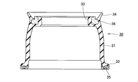
- FIG. 2 is a schematic cross-sectional view of a dust cover according to an embodiment of the present invention.
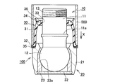
- FIG. 3 is a view for explaining the assembly procedure of the ball joint according to the embodiment of the present invention.
- FIG. 4 is a view for explaining the assembly procedure of the ball joint according to the embodiment of the present invention.
- FIG. 5 is a view for explaining the assembly procedure of the ball joint according to the embodiment of the present invention.
- FIG. 6 is a schematic cross-sectional view showing a state in which a ball joint according to an embodiment of the present invention is attached to a knuckle.
- FIG. 7 is a schematic cross-sectional view showing a state in which a ball joint according to a modification of the present invention is attached to a knuckle.
- FIG. 8 is a schematic cross-sectional view of a ball joint according to a conventional example.
- FIG. 1 is a schematic cross-sectional view showing a use state of a ball joint according to an embodiment of the present invention.
- disconnected by the surface containing the central axis of the axial part of the ball stud with which a ball joint is equipped is shown.
- FIG. 2 is a schematic cross-sectional view of a dust cover according to an embodiment of the present invention.
- transformed is shown.
- FIG. 3 to 5 are diagrams for explaining the assembly procedure of the ball joint according to the embodiment of the present invention.
- each member is shown in a schematic cross-sectional view.
- FIG. 6 is a schematic cross-sectional view showing a state in which a ball joint according to an embodiment of the present invention is attached to a knuckle.
- disconnected in terms of including the central axis of the axial part of the ball stud with which a ball joint is equipped is shown.
- the ball joint 100 is attached to a knuckle 200 as a mounting member provided on a vehicle body. Then, the ball joint 100 suppresses the intrusion of dust into the ball stud 10 having the spherical portion 12 at one end of the shaft portion 11, the socket 20 for rotatably and pivotally supporting the ball stud 10, and the socket 20. And a dust cover 30.
- the ball stud 10 is configured to be rotatable in the arrow A direction and configured to be swingable in the arrow B direction.
- the shaft portion 11 of the ball stud 10 is provided with an annular protrusion 11 a. Further, at the other end side of the shaft portion 11, a male screw 13 is formed.
- the ball joint 100 is fixed to the knuckle 200 by fastening the nut 300 to the male screw 13.
- the socket 20 includes an annular case 21, a bottom plate 22 fixed to the bottom side of the case 21, and a bearing 23 of the spherical portion 12.
- the bearing 23 has a bearing surface 23 a formed of a spherical surface having the same diameter as the radius of curvature of the spherical portion 12.
- the dust cover 30 has a role of preventing water, dust and the like from entering the joint portion in the socket 20 and preventing the outflow of grease from the joint portion.
- a positioning member 40 is provided which is mounted in advance to the shaft 11 before the ball joint 100 is attached to the knuckle 200, and positions the other end of the dust cover 30. There is.
- the dust cover 30 includes a seal body made of an elastic body such as rubber (for example, chloroprene rubber).
- the seal main body is provided with a deformable annular film-like body portion 31, one end side of the body portion 31, a fixed portion 32 fixed to the socket 20, and the other end side of the body portion 31
- the circumferential seal portion 33 and the dust seal portion 34 are integrally provided.
- a reinforcing ring 35 is provided inside the fixed portion 32. Further, a reinforcing ring 36 is provided also in the vicinity of the other end of the body portion 31.
- the dust cover 30 configured as described above, when the ball stud 10 swings with respect to the socket 20, the body portion 31 is deformed (see FIG. 1). Further, when the ball stud 10 rotates with respect to the socket 20, the inner peripheral seal portion 33 slides against the outer peripheral surface of the shaft portion 11 of the ball stud 10, and the dust seal portion 34 is the surface of the metal plate 41 in the positioning member 40. Slide against. Thereby, even if the ball stud 10 swings or rotates with respect to the socket 20, the dust cover 30 exerts a sealing function.
- the dust cover 30 is fixed to the end of the case 21 in the socket 20 by pushing the fixed portion 32 in the arrow X direction in FIG. 3 by the cylindrical jig 500.
- the positioning member 40 is mounted on the shaft portion 11.
- the positioning member 40 is provided along the inner peripheral surface of the metal plate 41 having the insertion hole through which the shaft portion 11 is inserted and the insertion hole in the metal plate 41, And an elastic member 42 in close contact with each other.
- the inner peripheral surface side of the metal plate 41 is subjected to bending so as to form the cylindrical portion 41 a.
- the elastic member 42 is integrally molded so that this cylindrical part 41a may be covered.
- the positioning member 40 is attached in advance to the shaft 11 before the ball joint 100 is attached to the knuckle 200 as the attachment member.
- the positioning member 40 has the inner circumferential seal portion 33 at a position opposite to the spherical portion 12 with respect to the shaft portion 11 with the annular protrusion 11 a in a state where the body portion 31 of the dust cover 30 is expanded outward. Plays a role in positioning the other end of the dust cover 30 so that the position is located (see FIG. 5).
- the elastic member 42 in the positioning member 40 is configured to be in close contact with the outer peripheral surface of the shaft portion 11 so that the sealing function is exhibited.
- the force by which the elastic member 42 is fixed to the shaft portion 11 by the elastic repulsive force by the elastic member 42 is set to be larger than the force by which the dust cover 30 in the bent state tries to return to the original state. ing.
- the positioning member 40 can position the other end of the dust cover 30 in a state in which the body portion 31 bulges outward.
- the ball joint 100 configured as described above is shipped to a vehicle maker or the like in a unitized state by the ball stud 10, the socket 20, the dust cover 30, and the positioning member 40.
- ⁇ Mounting procedure of ball joint to mounting member (knuckle)> a procedure for attaching the ball joint 100 according to the present embodiment to the knuckle 200 will be described.
- the ball joint 100 is attached to a knuckle 200 provided on the vehicle body.
- the shaft portion 11 is inserted into the insertion hole 210 provided in the knuckle 200.
- the nut 300 is fastened to the male screw 13 of the shaft portion 11, whereby the ball joint 100 is attached to the knuckle 200.
- the dust cover 30 is pushed toward the socket 20 by the knuckle 200, and the body 31 of the dust cover 30 is further expanded outward. It becomes.
- the dust cover 30 is positioned by the positioning member 40, and the body portion 31 is in a state of being expanded to some extent in advance. Therefore, in the process in which the dust cover 30 is pushed toward the socket 20 by the knuckle 200, a part of the body 31 does not deform so as to buckle inward.
- the inner circumferential seal portion 33 is configured to be positioned between the positioning member 40 and the annular projection 11a.
- annular recess 220 may be formed on the inner circumferential surface of the insertion hole 210 in the knuckle 200a, and the elastic member 42 may be fitted in the annular recess 220.
- FIG. 7 is a schematic cross-sectional view showing a state in which a ball joint according to a modification of the present invention is attached to a knuckle.
- the configuration other than the knuckle is the same as that of the above embodiment, so the same reference numeral is given to the same configuration, and the description thereof is omitted.
- the positioning member 40 is provided with the metal plate 41 and the elastic member 42 provided along the inner peripheral surface of the insertion hole in the metal plate 41 and in close contact with the outer peripheral surface of the shaft portion 11. It is configured. Accordingly, the positioning member 40 can be easily mounted on the shaft portion 11 by the elastic repulsive force of the elastic member 42.
- the elastic member 42 also exerts the sealing function.
- the force by which the elastic member 42 is fixed to the shaft portion 11 by the elastic repulsive force by the elastic member 42 is more than the force by which the dust cover 30 in the bent state returns to the original state. It is set to be large. Thereby, the inner circumferential seal portion 33 of the dust cover 30 can be easily positioned at a desired position.
- the inner circumferential seal portion 33 when the ball joint 100 is attached to the knuckle 200, the inner circumferential seal portion 33 is configured to be positioned between the positioning member 40 and the annular projection 11a. Thus, the inner circumferential seal portion 33 is located at a position opposite to the spherical portion 12 via the annular projection 11a. Therefore, when the ball joint 100 is attached to the knuckle 200, the inner circumferential seal portion 33 is not adversely affected by the annular projection 11a. Further, since the annular protrusion 11 a functions as a stopper, the movement of the dust cover 30 to the spherical portion 12 side at the other end side can be restricted.
- the present invention is applied even when the inner circumferential seal portion slides on the retainer. It can apply.
Landscapes
- Engineering & Computer Science (AREA)
- General Engineering & Computer Science (AREA)
- Mechanical Engineering (AREA)
- Pivots And Pivotal Connections (AREA)
- Sealing Devices (AREA)
- Diaphragms And Bellows (AREA)
Abstract
Description
被取付部材に取り付けられるボールジョイントであって、
軸部の一端に球形部を有するボールスタッドと、
前記球形部の軸受を有し、前記ボールスタッドを回転かつ揺動自在に支持するソケットと、
前記ソケット内にダストが侵入することを抑制するダストカバーと、
を備えるボールジョイントにおいて、
前記軸部は環状突起を備え、
前記ダストカバーは、
変形可能な胴体部と、
該胴体部の一端側に設けられ、前記ソケットに固定される被固定部と、
該胴体部の他端側に設けられ、前記軸部(本発明においては、ボールスタッドにおける軸部自体の他、当該軸部の外周面側に設けられた別の部材の場合も含む。以下、同様)の外周表面に対して摺動自在に備えられる内周シール部と、
該胴体部の他端側に設けられ、他端側に向かって伸びるダストシール部と、
を一体に有する弾性体製のシール本体を備えると共に、
ボールジョイントが前記被取付部材に取り付けられる前に前記軸部に対して予め装着され、かつ前記胴体部が外側に膨らんだ状態で、前記軸部に対して、前記環状突起を介して前記球形部とは反対側の位置に前記内周シール部が位置するように前記ダストカバーの他端を位置決めする位置決め部材が設けられていることを特徴とする。
前記軸部が挿通される挿通孔を有する金属板と、
該金属板における挿通孔の内周面に沿うように設けられ、前記軸部の外周面に対して密着する弾性部材と、
を備えるとよい。
図1~図6を参照して、本発明の実施例に係るボールジョイントについて説明する。図1は本発明の実施例に係るボールジョイントの使用状態を示す模式的断面図である。なお、図1においては、ボールジョイントに備えられるボールスタッドの軸部の中心軸線を含む面で切断した断面図を示している。図2は本発明の実施例に係るダストカバーの模式的断面図である。なお、図2においては、ダストカバーが変形していない状態で、環状のダストカバーの中心軸線を含む面で切断した断面図を示している。図3~図5は本発明の実施例に係るボールジョイントの組み立て手順を説明する図である。各図においては、各部材を模式的断面図にて示している。図6は本発明の実施例に係るボールジョイントをナックルに取り付けた状態を示す模式的断面図である。なお、図6においては、ボールジョイントに備えられるボールスタッドの軸部の中心軸線を含む面で切断した断面図を示している。
特に、図1を参照して、本実施例に係るボールジョイント100の一例を説明する。ボールジョイント100は、車体に設けられた被取付部材としてのナックル200に取り付けられる。そして、ボールジョイント100は、軸部11の一端に球形部12を有するボールスタッド10と、ボールスタッド10を回転かつ揺動自在に支持するソケット20と、ソケット20内にダストが侵入することを抑制するダストカバー30とを備えている。なお、図1に示すように、ボールスタッド10は、矢印A方向に回転自在に構成され、かつ矢印B方向に揺動自在に構成される。ボールスタッド10の軸部11には、環状突起11aが備えられている。また、軸部11の他端側には、オネジ13が形成されている。このオネジ13にナット300が締結されることにより、ボールジョイント100はナックル200に固定される。
ダストカバー30の全体構成について、特に図2を参照して説明する。ダストカバー30は、ゴム(例えば、クロロプレンゴム)などの弾性体製のシール本体を備えている。シール本体は、変形可能な環状かつ膜状の胴体部31と、胴体部31の一端側に設けられ、ソケット20に固定される被固定部32と、胴体部31の他端側に設けられる内周シール部33及びダストシール部34とを一体に有している。被固定部32の内部には補強環35が設けられている。また、胴体部31の他端付近の内部にも補強環36が設けられている。
本実施例に係るボールジョイントの組み立て手順について、図3~図5を参照して説明する。まず、円筒状の治具500によって、図3中矢印X方向に被固定部32が押し込まれることで、ソケット20におけるケース21の端部にダストカバー30が固定される。次に、位置決め部材40が軸部11に装着される。ここで、位置決め部材40は、軸部11が挿通される挿通孔を有する金属板41と、この金属板41における挿通孔の内周面に沿うように設けられ、軸部11の外周面に対して密着する弾性部材42とから構成される。なお、本実施例においては、金属板41の内周面側には、円筒部41aを形成するように曲げ加工が施されている。そして、この円筒部41aを覆うように弾性部材42が一体成形されている。
特に、図6を参照して、本実施例に係るボールジョイント100のナックル200への取り付け手順について説明する。出荷先において、ボールジョイント100は、車体に設けられたナックル200に取り付けられる。具体的には、ナックル200に設けられた挿通孔210に軸部11が挿入される。そして、軸部11のオネジ13にナット300が締結されることによって、ナックル200にボールジョイント100が取り付けられる。ここで、挿通孔210に対して軸部11が挿入される過程で、ダストカバー30は、ナックル200によってソケット20側に押し込まれて、ダストカバー30の胴体部31は、更に外側に膨らんだ状態となる。ここで、上記の通り、ダストカバー30は、位置決め部材40によって位置決めされており、予め胴体部31はある程度膨らんだ状態となっている。従って、ダストカバー30がナックル200によってソケット20側に押し込まれる過程で、胴体部31の一部が内側に座屈するように変形してしまうことはない。また、ボールジョイント100がナックル200に取り付けられた状態においては、内周シール部33は、位置決め部材40と環状突起11aとの間に位置するように構成されている。
以上のように構成される本実施例に係るボールジョイント100によれば、ボールジョイント100がナックル200に取り付けられる前に、位置決め部材40によって、胴体部31が膨らんだ状態で、ダストカバー30の他端が位置決めされている。従って、ボールジョイント100がナックル200に取り付けられる際に、ダストカバー30における胴体部31の一部が内側に座屈するように変形してしまうことが抑制される。このように、ダストカバー30の姿勢を安定化することができる。
上記実施例においては、内周シール部33が、ボールスタッド10の軸部11自体の外周表面に対して摺動する場合を示した。しかしながら、本発明においては、ボールスタッド10の軸部11の外周面側に設けられた別の部材の外周表面に対して内周シール部が摺動自在に構成される場合にも適用可能である。例えば、特開平11-63245号公報に開示された技術のように、フェルールが備えられる構成においては、内周シール部がフェルールに摺動する場合にも、本発明を適用することができる。また、実開平3-32211号公報に開示された技術のように、フランジを有する保持部材(リテーナ)が備えられる構成においては、内周シール部がリテーナに摺動する場合にも、本発明を適用することができる。
11 軸部
11a 環状突起
12 球形部
13 オネジ
20 ソケット
21 ケース
22 底板
23 軸受
23a 軸受面
30 ダストカバー
31 胴体部
32 被固定部
33 内周シール部
34 ダストシール部
35 補強環
36 補強環
40 位置決め部材
41 金属板
41a 円筒部
42 弾性部材
100 ボールジョイント
200,200a ナックル
210 挿通孔
220 環状凹部
300 ナット
500 治具
Claims (5)
- 被取付部材に取り付けられるボールジョイントであって、
軸部の一端に球形部を有するボールスタッドと、
前記球形部の軸受を有し、前記ボールスタッドを回転かつ揺動自在に支持するソケットと、
前記ソケット内にダストが侵入することを抑制するダストカバーと、
を備えるボールジョイントにおいて、
前記軸部は環状突起を備え、
前記ダストカバーは、
変形可能な胴体部と、
該胴体部の一端側に設けられ、前記ソケットに固定される被固定部と、
該胴体部の他端側に設けられ、前記軸部の外周表面に対して摺動自在に備えられる内周シール部と、
該胴体部の他端側に設けられ、他端側に向かって伸びるダストシール部と、
を一体に有する弾性体製のシール本体を備えると共に、
ボールジョイントが前記被取付部材に取り付けられる前に前記軸部に対して予め装着され、かつ前記胴体部が外側に膨らんだ状態で、前記軸部に対して、前記環状突起を介して前記球形部とは反対側の位置に前記内周シール部が位置するように前記ダストカバーの他端を位置決めする位置決め部材が設けられていることを特徴とするボールジョイント。 - 前記位置決め部材は、
前記軸部が挿通される挿通孔を有する金属板と、
該金属板における挿通孔の内周面に沿うように設けられ、前記軸部の外周面に対して密着する弾性部材と、
を備えることを特徴とする請求項1に記載のボールジョイント。 - 前記弾性部材による弾性反発力により、該弾性部材が前記軸部に固定される力は、撓んだ状態の前記ダストカバーが元の状態に戻ろうとする力よりも大きいことを特徴とする請求項2に記載のボールジョイント。
- 前記ダストシール部は、前記金属板の表面に対して摺動自在に設けられていることを特徴とする請求項2または3に記載のボールジョイント。
- ボールジョイントが前記被取付部材に取り付けられた状態においては、前記内周シール部は、前記位置決め部材と前記環状突起との間に位置することを特徴とする請求項1~4のいずれか一つに記載のボールジョイント。
Priority Applications (4)
| Application Number | Priority Date | Filing Date | Title |
|---|---|---|---|
| CN201680029032.1A CN107614900B (zh) | 2015-05-28 | 2016-05-26 | 球窝接头 |
| EP16800089.1A EP3306121B1 (en) | 2015-05-28 | 2016-05-26 | Ball joint |
| US15/576,006 US10563691B2 (en) | 2015-05-28 | 2016-05-26 | Ball joint |
| JP2017520799A JP6315147B2 (ja) | 2015-05-28 | 2016-05-26 | ボールジョイント |
Applications Claiming Priority (2)
| Application Number | Priority Date | Filing Date | Title |
|---|---|---|---|
| JP2015108511 | 2015-05-28 | ||
| JP2015-108511 | 2015-05-28 |
Publications (1)
| Publication Number | Publication Date |
|---|---|
| WO2016190385A1 true WO2016190385A1 (ja) | 2016-12-01 |
Family
ID=57393419
Family Applications (1)
| Application Number | Title | Priority Date | Filing Date |
|---|---|---|---|
| PCT/JP2016/065566 Ceased WO2016190385A1 (ja) | 2015-05-28 | 2016-05-26 | ボールジョイント |
Country Status (5)
| Country | Link |
|---|---|
| US (1) | US10563691B2 (ja) |
| EP (1) | EP3306121B1 (ja) |
| JP (1) | JP6315147B2 (ja) |
| CN (1) | CN107614900B (ja) |
| WO (1) | WO2016190385A1 (ja) |
Cited By (3)
| Publication number | Priority date | Publication date | Assignee | Title |
|---|---|---|---|---|
| CN108859752A (zh) * | 2017-05-11 | 2018-11-23 | 舍弗勒技术股份两合公司 | 在分离系统区域中的波纹管连接 |
| US10655733B2 (en) | 2016-11-18 | 2020-05-19 | Schaublin Sa | Elastomeric seal having impact protecting protrusions |
| US20220204079A1 (en) * | 2019-09-02 | 2022-06-30 | Yamaha Hatsudoki Kabushiki Kaisha | Leaning vehicle |
Families Citing this family (8)
| Publication number | Priority date | Publication date | Assignee | Title |
|---|---|---|---|---|
| EP3184832B1 (en) * | 2014-08-21 | 2020-06-24 | NOK Corporation | Dust cover |
| CN107850112A (zh) * | 2015-07-27 | 2018-03-27 | Nok株式会社 | 球铰用防尘罩 |
| EP3428463A1 (en) * | 2016-03-10 | 2019-01-16 | Nok Corporation | Dust cover and sealing structure |
| CN109163008A (zh) * | 2018-09-25 | 2019-01-08 | 安徽骆氏升泰汽车零部件有限公司 | 一种压装控制臂球销卡簧装置 |
| JPWO2020071032A1 (ja) * | 2018-10-01 | 2021-02-15 | Nok株式会社 | ダストカバー |
| US11059161B2 (en) * | 2018-12-10 | 2021-07-13 | Storm Pneumatic Tool Co., Ltd. | Joint fixing structure of hand-held power tool |
| US11767879B2 (en) * | 2018-12-21 | 2023-09-26 | Agco International Gmbh | Bearing housing design with dual o-ring function |
| US12281704B2 (en) * | 2023-01-13 | 2025-04-22 | Caterpillar Inc. | Seal member for joint assembly of a machine and systems, methods, and assemblies thereof |
Citations (4)
| Publication number | Priority date | Publication date | Assignee | Title |
|---|---|---|---|---|
| JPH1163245A (ja) * | 1997-08-21 | 1999-03-05 | Nok Corp | ダストカバー |
| JP2000230540A (ja) * | 1999-02-12 | 2000-08-22 | Somic Ishikawa:Kk | ボールジョイント |
| JP2003247529A (ja) * | 2002-02-21 | 2003-09-05 | Musashi Seimitsu Ind Co Ltd | ボールジョイント |
| DE102011085543A1 (de) * | 2011-11-02 | 2013-05-02 | Zf Friedrichshafen Ag | Kugelzapfenanordnung für Kugelgelenk |
Family Cites Families (17)
| Publication number | Priority date | Publication date | Assignee | Title |
|---|---|---|---|---|
| US2456546A (en) * | 1944-01-01 | 1948-12-14 | Thompson Prod Inc | Tie rod joint seal |
| GB949966A (en) | 1959-12-30 | 1964-02-19 | Automotive Prod Co Ltd | Improvements in and relating to sealing boots for joint assemblies |
| US3208779A (en) * | 1962-10-22 | 1965-09-28 | Gen Motors Corp | Ball joint dirt seal valve |
| BE754623A (fr) | 1969-08-12 | 1971-01-18 | Rau Swf Autozubehoer | Dispositif pour la disposition d'un tenon spherique, plus particulierement d'une manivelle de moteur dans la tringlerie des essuie-glaces d'unvehicule automobile |
| JPS5454769U (ja) | 1977-09-26 | 1979-04-16 | ||
| JPS5839214Y2 (ja) * | 1978-05-16 | 1983-09-05 | トヨタ自動車株式会社 | サスペンシヨンボ−ルジヨイント取付部構造 |
| JPH048907A (ja) | 1990-04-26 | 1992-01-13 | T R W S I Kk | ボールジョイント用プロテクター |
| JP3412480B2 (ja) | 1997-10-09 | 2003-06-03 | 三菱自動車工業株式会社 | ボールジョイント |
| JP4097118B2 (ja) * | 2001-10-29 | 2008-06-11 | 武蔵精密工業株式会社 | ボールジョイント |
| WO2003056194A1 (fr) * | 2001-12-25 | 2003-07-10 | Musashi Seimitsu Kogyo Kabushiki Kaisha | Joint spherique |
| JP3980903B2 (ja) * | 2002-02-21 | 2007-09-26 | 武蔵精密工業株式会社 | ボールジョイント |
| JP3980902B2 (ja) * | 2002-02-21 | 2007-09-26 | 武蔵精密工業株式会社 | ボールジョイント |
| DE10207779C1 (de) * | 2002-02-23 | 2003-10-30 | Paguag Gmbh | Dichtungsanordnung mit Dichtungsbalg und Manschette |
| DE102004001465B4 (de) * | 2004-01-08 | 2006-04-20 | Zf Friedrichshafen Ag | Kugelgelenk, vorzugsweise zum Einsatz in Fahrzeugen |
| DE102007055251A1 (de) * | 2007-11-16 | 2009-07-16 | Zf Friedrichshafen Ag | Gelenk- und/oder Lageranordnung |
| DE102008014695B4 (de) * | 2008-03-18 | 2023-08-03 | THK RHYTHM AUTOMOTIVE GmbH | Dichtungsbaugruppe eines Kugelgelenks sowie Kugelgelenk |
| JP2014219045A (ja) | 2013-05-08 | 2014-11-20 | Nok株式会社 | ボールジョイント用ダストカバー |
-
2016
- 2016-05-26 EP EP16800089.1A patent/EP3306121B1/en active Active
- 2016-05-26 JP JP2017520799A patent/JP6315147B2/ja not_active Expired - Fee Related
- 2016-05-26 CN CN201680029032.1A patent/CN107614900B/zh not_active Expired - Fee Related
- 2016-05-26 WO PCT/JP2016/065566 patent/WO2016190385A1/ja not_active Ceased
- 2016-05-26 US US15/576,006 patent/US10563691B2/en active Active
Patent Citations (4)
| Publication number | Priority date | Publication date | Assignee | Title |
|---|---|---|---|---|
| JPH1163245A (ja) * | 1997-08-21 | 1999-03-05 | Nok Corp | ダストカバー |
| JP2000230540A (ja) * | 1999-02-12 | 2000-08-22 | Somic Ishikawa:Kk | ボールジョイント |
| JP2003247529A (ja) * | 2002-02-21 | 2003-09-05 | Musashi Seimitsu Ind Co Ltd | ボールジョイント |
| DE102011085543A1 (de) * | 2011-11-02 | 2013-05-02 | Zf Friedrichshafen Ag | Kugelzapfenanordnung für Kugelgelenk |
Cited By (4)
| Publication number | Priority date | Publication date | Assignee | Title |
|---|---|---|---|---|
| US10655733B2 (en) | 2016-11-18 | 2020-05-19 | Schaublin Sa | Elastomeric seal having impact protecting protrusions |
| CN108859752A (zh) * | 2017-05-11 | 2018-11-23 | 舍弗勒技术股份两合公司 | 在分离系统区域中的波纹管连接 |
| CN108859752B (zh) * | 2017-05-11 | 2024-03-01 | 舍弗勒技术股份两合公司 | 在分离系统区域中的波纹管连接 |
| US20220204079A1 (en) * | 2019-09-02 | 2022-06-30 | Yamaha Hatsudoki Kabushiki Kaisha | Leaning vehicle |
Also Published As
| Publication number | Publication date |
|---|---|
| JPWO2016190385A1 (ja) | 2018-02-15 |
| EP3306121A1 (en) | 2018-04-11 |
| CN107614900B (zh) | 2020-01-24 |
| US20180149192A1 (en) | 2018-05-31 |
| JP6315147B2 (ja) | 2018-04-25 |
| US10563691B2 (en) | 2020-02-18 |
| EP3306121B1 (en) | 2019-09-25 |
| CN107614900A (zh) | 2018-01-19 |
| EP3306121A4 (en) | 2018-11-07 |
Similar Documents
| Publication | Publication Date | Title |
|---|---|---|
| JP6315147B2 (ja) | ボールジョイント | |
| JP6323561B2 (ja) | ダストカバー | |
| JP6376426B2 (ja) | ボールジョイント | |
| CN108368870B (zh) | 防尘罩以及密封构造 | |
| JPWO2020071032A1 (ja) | ダストカバー | |
| JP6540818B2 (ja) | ダストカバー | |
| US20130287478A1 (en) | Ball joint | |
| WO2017018168A1 (ja) | ボールジョイント用ダストカバー | |
| CN111742155B (zh) | 球接头和防尘罩 | |
| JPWO2017154672A1 (ja) | ダストカバー及び密封構造 | |
| JP6899299B2 (ja) | ダストカバー | |
| JP7117924B2 (ja) | ダストカバー | |
| TWI745568B (zh) | 球形接頭的密封構件 | |
| EP3686447B1 (en) | Ball joint and dust cover | |
| CN111094772B (zh) | 球形接头 | |
| JP2019132332A (ja) | ダストカバー | |
| JP2017002925A (ja) | ダストカバー | |
| JP2016130559A (ja) | ダストカバー |
Legal Events
| Date | Code | Title | Description |
|---|---|---|---|
| 121 | Ep: the epo has been informed by wipo that ep was designated in this application |
Ref document number: 16800089 Country of ref document: EP Kind code of ref document: A1 |
|
| ENP | Entry into the national phase |
Ref document number: 2017520799 Country of ref document: JP Kind code of ref document: A |
|
| WWE | Wipo information: entry into national phase |
Ref document number: 15576006 Country of ref document: US |
|
| NENP | Non-entry into the national phase |
Ref country code: DE |
|
| WWE | Wipo information: entry into national phase |
Ref document number: 2016800089 Country of ref document: EP |