WO2016190392A1 - 累進屈折力レンズの設計方法及び設計装置 - Google Patents
累進屈折力レンズの設計方法及び設計装置 Download PDFInfo
- Publication number
- WO2016190392A1 WO2016190392A1 PCT/JP2016/065598 JP2016065598W WO2016190392A1 WO 2016190392 A1 WO2016190392 A1 WO 2016190392A1 JP 2016065598 W JP2016065598 W JP 2016065598W WO 2016190392 A1 WO2016190392 A1 WO 2016190392A1
- Authority
- WO
- WIPO (PCT)
- Prior art keywords
- power
- addition
- progressive
- diopter
- region
- Prior art date
- Legal status (The legal status is an assumption and is not a legal conclusion. Google has not performed a legal analysis and makes no representation as to the accuracy of the status listed.)
- Ceased
Links
Images

















Classifications
-
- G—PHYSICS
- G02—OPTICS
- G02C—SPECTACLES; SUNGLASSES OR GOGGLES INSOFAR AS THEY HAVE THE SAME FEATURES AS SPECTACLES; CONTACT LENSES
- G02C7/00—Optical parts
- G02C7/02—Lenses; Lens systems ; Methods of designing lenses
- G02C7/024—Methods of designing ophthalmic lenses
- G02C7/027—Methods of designing ophthalmic lenses considering wearer's parameters
-
- G—PHYSICS
- G02—OPTICS
- G02C—SPECTACLES; SUNGLASSES OR GOGGLES INSOFAR AS THEY HAVE THE SAME FEATURES AS SPECTACLES; CONTACT LENSES
- G02C7/00—Optical parts
- G02C7/02—Lenses; Lens systems ; Methods of designing lenses
- G02C7/024—Methods of designing ophthalmic lenses
- G02C7/025—Methods of designing ophthalmic lenses considering parameters of the viewed object
-
- G—PHYSICS
- G02—OPTICS
- G02C—SPECTACLES; SUNGLASSES OR GOGGLES INSOFAR AS THEY HAVE THE SAME FEATURES AS SPECTACLES; CONTACT LENSES
- G02C7/00—Optical parts
- G02C7/02—Lenses; Lens systems ; Methods of designing lenses
- G02C7/06—Lenses; Lens systems ; Methods of designing lenses bifocal; multifocal ; progressive
-
- G—PHYSICS
- G02—OPTICS
- G02C—SPECTACLES; SUNGLASSES OR GOGGLES INSOFAR AS THEY HAVE THE SAME FEATURES AS SPECTACLES; CONTACT LENSES
- G02C7/00—Optical parts
- G02C7/02—Lenses; Lens systems ; Methods of designing lenses
- G02C7/06—Lenses; Lens systems ; Methods of designing lenses bifocal; multifocal ; progressive
- G02C7/061—Spectacle lenses with progressively varying focal power
-
- G—PHYSICS
- G02—OPTICS
- G02C—SPECTACLES; SUNGLASSES OR GOGGLES INSOFAR AS THEY HAVE THE SAME FEATURES AS SPECTACLES; CONTACT LENSES
- G02C7/00—Optical parts
- G02C7/02—Lenses; Lens systems ; Methods of designing lenses
- G02C7/06—Lenses; Lens systems ; Methods of designing lenses bifocal; multifocal ; progressive
- G02C7/061—Spectacle lenses with progressively varying focal power
- G02C7/063—Shape of the progressive surface
- G02C7/065—Properties on the principal line
-
- G—PHYSICS
- G06—COMPUTING OR CALCULATING; COUNTING
- G06F—ELECTRIC DIGITAL DATA PROCESSING
- G06F30/00—Computer-aided design [CAD]
-
- G—PHYSICS
- G06—COMPUTING OR CALCULATING; COUNTING
- G06F—ELECTRIC DIGITAL DATA PROCESSING
- G06F30/00—Computer-aided design [CAD]
- G06F30/20—Design optimisation, verification or simulation
-
- G—PHYSICS
- G06—COMPUTING OR CALCULATING; COUNTING
- G06F—ELECTRIC DIGITAL DATA PROCESSING
- G06F2111/00—Details relating to CAD techniques
- G06F2111/10—Numerical modelling
-
- Y—GENERAL TAGGING OF NEW TECHNOLOGICAL DEVELOPMENTS; GENERAL TAGGING OF CROSS-SECTIONAL TECHNOLOGIES SPANNING OVER SEVERAL SECTIONS OF THE IPC; TECHNICAL SUBJECTS COVERED BY FORMER USPC CROSS-REFERENCE ART COLLECTIONS [XRACs] AND DIGESTS
- Y02—TECHNOLOGIES OR APPLICATIONS FOR MITIGATION OR ADAPTATION AGAINST CLIMATE CHANGE
- Y02E—REDUCTION OF GREENHOUSE GAS [GHG] EMISSIONS, RELATED TO ENERGY GENERATION, TRANSMISSION OR DISTRIBUTION
- Y02E60/00—Enabling technologies; Technologies with a potential or indirect contribution to GHG emissions mitigation
-
- Y—GENERAL TAGGING OF NEW TECHNOLOGICAL DEVELOPMENTS; GENERAL TAGGING OF CROSS-SECTIONAL TECHNOLOGIES SPANNING OVER SEVERAL SECTIONS OF THE IPC; TECHNICAL SUBJECTS COVERED BY FORMER USPC CROSS-REFERENCE ART COLLECTIONS [XRACs] AND DIGESTS
- Y04—INFORMATION OR COMMUNICATION TECHNOLOGIES HAVING AN IMPACT ON OTHER TECHNOLOGY AREAS
- Y04S—SYSTEMS INTEGRATING TECHNOLOGIES RELATED TO POWER NETWORK OPERATION, COMMUNICATION OR INFORMATION TECHNOLOGIES FOR IMPROVING THE ELECTRICAL POWER GENERATION, TRANSMISSION, DISTRIBUTION, MANAGEMENT OR USAGE, i.e. SMART GRIDS
- Y04S40/00—Systems for electrical power generation, transmission, distribution or end-user application management characterised by the use of communication or information technologies, or communication or information technology specific aspects supporting them
- Y04S40/20—Information technology specific aspects, e.g. CAD, simulation, modelling, system security
Definitions
- the present invention relates to a design method and design apparatus for a progressive power lens.
- the spectacle lens includes a progressive addition lens in addition to a single focus lens.
- a conventional progressive-power lens has a progressive zone in which the radius of curvature progressively changes along the main meridian passing through the center of the lens, and a predetermined distance between the distance center and the near center on the main meridian.
- Patent Document 1 There is a spectacle lens to which an addition is added.
- a fitting point is set between the start point and end point of the progressive band, and the average gradient of the addition power from the start point of the progressive band to the vicinity of the fitting point, and the fitting point
- the average gradient of the addition power from the vicinity to the end point of the progressive zone is different, and the addition power of about 0.5 diopters is added to the fitting point for the distance power.
- the target addition is set to the fitting point.
- a refractive power of about 0.5 diopters as a target addition power at a footing point is compared with a distance power regardless of the addition power (prescription addition power) prescribed for each user. Since it is added, the distance of about 2 m set as the target distance can be clearly seen regardless of the user's prescription addition degree.
- lens design is performed by controlling the surface power in order to set a target addition (for example, 0.5 diopter) at a fitting point.
- a target addition for example, 0.5 diopter
- An object of the present invention is to provide a design method and a design apparatus for a progressive-power lens capable of maintaining the addition power at the fitting point at a target value when wearing glasses.
- the method for designing a progressive-power lens according to the present invention provides an intermediate region in which the addition power continuously changes between the first region for applying the first refractive power and the second region for applying the second refractive power, A main meridian is provided in the first region, the intermediate region, and the second region, a progressive start point through which the main meridian passes is set in a portion close to the first region of the intermediate region, and a main point is set in a portion close to the second region in the intermediate region.
- a first model is designed.
- the face number is controlled.
- a visual simulation assuming the state of wearing glasses is performed on the first model.
- a device using a known ray tracing method can be used.
- a correction amount for correcting the difference between the simulation value of the addition at the fitting point and the target addition is calculated, and the addition obtained by adding the correction amount to the original target addition is again used as the fitting point.
- the visual simulation assuming the actual wearing state is performed on the first model. Therefore, in the second model, the target addition at the fitting point is deviated from the addition at the time of wearing. There are few things.
- the simulation step includes the objective addition of the first model, the prescription addition defined by the difference between the first refractive power and the second refractive power, the spherical power of the region to which the first refractive power is applied, and the astigmatic power.
- Astigmatism axis direction, prism refractive power, and prism base direction at least one parameter value is changed multiple times
- the calculation process calculates the correction amount for each simulation, and the design process is stored in advance
- a fitting point on the main meridian for designing the second model based on the relationship between the correction amount and the degree
- prescription addition spherical power, astigmatism power, astigmatism axis direction, prism refractive power and prism base direction.
- a configuration in which the addition power at the corresponding position is set is preferable.
- the factors when the added power when the progressive addition lens is actually worn deviates from the set target power are the target power, prescription power, spherical power, astigmatism power, and astigmatic axis direction.
- a correction amount is obtained for each data relating to these factors. Then, an appropriate correction amount is obtained from these data. Therefore, the amount by which the target addition at the fitting point deviates from the addition at the time of wearing can be made extremely small.
- a determination process for re-simulating the spectacle wearing state and determining whether the re-simulation value matches the desired value based on the difference between the re-simulation value and the desired value In the determination step, when it is determined that the re-simulation value does not match the desired value, a configuration in which the design step is performed again is preferable. In this configuration, it is possible to confirm whether or not the correction of the progressive-power lens after the design is correctly performed by the determination step. If the correction is not performed correctly, the design process is performed again, so that the deviation of the target addition at the fitting point from the addition at the time of wearing can be reliably reduced.
- the fitting point is set between the progressive start point and the progressive end point and along the extension line of the portion passing through the first region of the main meridian. It is set according to the target distance to the target position to be visually recognized, and the average gradient of the addition between the progressive start point and the fitting point is different from the average gradient of the addition between the fitting point and the progressive end point.
- the structure set to is preferable. With this configuration, the same effect as described above can be achieved in a lens that can clearly see the place set as the target distance regardless of the user's prescription addition.
- an intermediate region in which the addition power continuously changes is provided between the first region for applying the first refractive power and the second region for applying the second refractive power.
- the first meridian is provided in the first region, the intermediate region, and the second region, and the progressive start point through which the main meridian passes is set in the portion close to the first region of the intermediate region, and the portion close to the second region in the intermediate region Progressive end point where the main meridian passes through is set, and the fitting power is set at a position along the extension line of the part passing through the first region of the main meridian between the progressive start point and the progressive end point
- An apparatus for designing a lens for a first model designed by setting a desired addition of a desired value at a position corresponding to a fitting point on the main meridian, a visual simulation assuming a spectacle wearing state, First Objective addition of the model, prescription addition defined by the difference between the first refractive power and the second refractive power, spher
- a calculation unit for calculating a correction amount for correcting the difference between the simulation value of the addition at the fitting point and the target addition for each simulation, and the target addition and prescription addition based on the result calculated by the calculation unit.
- Spherical power, astigmatism power, astigmatic axis direction, prism refractive power and prism base direction at least one
- a storage unit for storing a relationship with a positive amount
- an input unit for inputting at least one information of a target addition, a prescription addition, a spherical power, an astigmatism power, an astigmatism axis direction, a prism refractive power, and a prism base direction
- an input A control unit for obtaining a correction amount for designing the second model from the information input from the unit and the information stored in the storage unit, and the main meridian by adding the correction amount obtained by the control unit to the target addition
- a design unit that sets the second model again at a position corresponding to the upper fitting point.
- the top view which shows typically the progressive-power lens designed by embodiment of this invention.
- the graph which shows the progressive refractive power lens designed by embodiment of this invention typically, and shows the relationship between refractive power and the position on a main meridian. Schematic which shows the design apparatus of the progressive-power lens concerning 1st Embodiment.
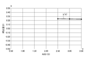
- the graph which shows the relationship between prescription addition degree ADD and correction amount The graph which shows the relationship between prescription addition degree ADD and correction amount.
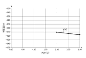
- the graph which shows the relationship between prescription addition degree ADD and correction amount The graph which shows the relationship between prescription addition degree ADD and correction amount.
- the graph which shows the relationship between prescription addition degree ADD and correction amount The graph which shows the relationship between prescription addition degree ADD and correction amount.
- the graph which shows the relationship between prescription addition degree ADD and correction amount The graph which shows the relationship between prescription addition degree ADD and correction amount.
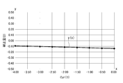
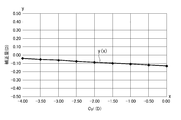
- the graph which shows the relationship between prescription addition degree ADD and correction amount The graph which shows the relationship between prescription addition degree ADD and correction amount. The graph which shows the relationship between prescription addition degree ADD and correction amount. The graph which shows the relationship between prescription addition degree ADD and correction amount. The graph which shows the relationship between astigmatism power Cyl and correction amount. The graph which shows the relationship between astigmatism power Cyl and correction amount. The graph which shows the relationship between astigmatism power Cyl and correction amount. The graph which shows the relationship between astigmatism power Cyl and correction amount. The graph which shows the relationship between astigmatism power Cyl and correction amount. The graph which shows the relationship between astigmatism power Cyl and correction amount. The graph which shows the relationship between astigmatism power Cyl and correction amount. The graph which shows the relationship between astigmatism power Cyl and correction amount. The graph which shows the relationship between astigmatism power Cyl and correction amount. The graph which shows the relationship between astigmatism power Cyl and correction amount. The graph which shows the relationship between astigmatism
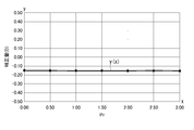
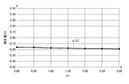
- the graph which shows the relationship between prism refractive power Pr and correction amount The graph which shows the relationship between prism refractive power Pr and correction amount. The graph which shows the relationship between prism refractive power Pr and correction amount. The graph which shows the relationship between prism refractive power Pr and correction amount. The graph which shows the relationship between prism refractive power Pr and correction amount. The graph which shows the relationship between prism refractive power Pr and correction amount. The graph which shows the relationship between prism refractive power Pr and correction amount. The graph which shows the relationship between prism refractive power Pr and correction amount. The graph which shows the relationship between prism refractive power Pr and correction amount. The surface refractive power distribution map of the first model.
- the principal power of 2nd Embodiment of this invention is shown, and the surface refractive power distribution map after the determination process.
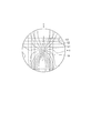
- FIG. 1A shows the front of the progressive-power lens.
- the progressive addition lens 1 includes a first region 1A that provides a first refractive power D1, a second region 1B that provides a second refractive power D2, a first region 1A, and a second region.
- the intermediate region 1C disposed between 1B and the side regions 1D disposed on both sides of the intermediate region 1C.
- the first area 1A is an area for distance vision
- the second area 1B is an area for near vision.
- the intermediate region 1C is a progressive region where the addition power continuously changes.
- the main meridian C is the position on the lens where the line of sight passes most frequently when performing near vision from far vision (moving from the upper side of the lens to the lower side) while wearing a progressive power lens. It is a line along.
- the eyeball side is a progressive surface and the object side is a spherical surface.
- a progressive start point PS is set at a position on the main meridian C and close to the first area 1A of the intermediate area 1C, and a progressive end point PE is set at a position close to the second area 1B.
- the main meridian C corresponds to the first region 1A, the line portion C1 set on the Y axis along the top and bottom, and the second region 1B corresponds to the second region 1B and is separated from the Y axis by the dimension I in the X axis direction, and the Y axis And a line part C3 corresponding to the intermediate area 1C and connecting the progressive start point PS and the progressive end point PE.
- a first measurement reference point P1 for measuring the magnitude of the first refractive power imparted in the first region 1A is set in the first region 1A.
- the first measurement reference point P1 is set on the main meridian and in the vicinity above the progressive start point PS.
- the first measurement reference point P1 may be located at the center of a first refractive power measurement reference circle (not shown), and the progressive start point PS may coincide with the arc portion of the first refractive power measurement reference circle.
- a second measurement reference point P2 for measuring the magnitude of the second refractive power imparted in the second region 1B is set in the second region 1B.
- the second measurement reference point P2 is set on the main meridian C and near the progressive end point PE.
- the second measurement reference point P2 may be positioned at the center of the first refractive power measurement reference circle (not shown), and the progressive end point PE may coincide with the arc portion of the first refractive power measurement reference circle.
- a fitting point FP is set at a position between the progressive start point PS and the progressive end point PE and along the extended line of the line portion C1 of the main meridian C.
- the extension line is a region located in the intermediate region 1C of the Y axis.
- the fitting point FP is set on the first area 1A side from the origin O, but may be coincident with the origin O, or may be set on the second area 1B side from the origin O. Good.
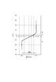
- the refractive power at the position on the main meridian C is shown.
- the refractive power of the line C1 in the main meridian C is the first refractive power D1 diopter from the first region 1A to the progressive start point PS, and the progressive end from the progressive start point PS of the line C3. It increases from D1 diopter to D2 diopter over the point PE, and remains D2 diopter from the progressive end point PE of the line part C2 to the lower part of the second region 1B.
- the addition at the fitting point FP is set as the target addition FAD.
- the target addition FAD is set in relation to a desired value regardless of the size of the prescription addition ADD.
- the desired value is set according to the target distance to the target position that the wearer wants to clearly see.
- the target addition FAD is (1 / d).
- the average gradient M of the addition between the progressive start point PS and the fitting point FP is set to be different from the average gradient N of the addition between the fitting point FP and the progressive end point PE.
- FIG. 2 shows an outline of the progressive-power lens designing apparatus 10 according to the first embodiment.
- the design apparatus 10 includes a simulation apparatus 20 and a computer 30.
- the simulation apparatus 20 performs a visual simulation assuming a spectacle wearing state on a first model (not shown) designed by setting a target addition FAD corresponding to the target distance d at the fitting point FP.
- a known ray tracing method is used.
- the light ray incident on the objective side surface of the lens is used to calculate the route along which the light ray comes out from the eyeball side surface of the lens and is collected.
- the ray tracing method is used.
- the simulation value SDD of the addition at the fitting point FP of the first model is calculated.
- the simulation device 20 has an input device (not shown) for inputting parameters and lens information other than the parameters.
- the parameters include objective addition FAD, prescription addition ADD, spherical power Sph of first region 1A to which first refractive power D1 is applied, astigmatism power Cyl, astigmatism axis direction Ax, prism refractive power Pr, prism base.
- the lens information includes the refractive index n of the lens, the fitting point FP, the progressive start point PS, the progressive end point PE, the first measurement reference point P1, and the second measurement.
- the visual simulation is performed a plurality of times by selecting a predetermined parameter and changing the value of the selected parameter.
- the computer 30 designs a progressive-power lens based on the result obtained by the simulation apparatus 20, and includes a processing unit 40 and an input unit 50.
- the input unit 50 inputs various pieces of information on the progressive-power lens to be designed, and examples of the input means include a keyboard and other input means in a personal computer.
- the input data input through the input unit 50 includes the target addition FAD, the prescription addition ADD, the spherical power Sph of the first region 1A to which the first refractive power D1 is applied, the astigmatic power Cyl, the astigmatic axis direction Ax, and the prism refractive power.
- Pr prism base direction PBE, convex curve ABC, lens center thickness CT, and lens information includes the refractive index n of the lens, the fitting point FP, the progressive start point PS, the progressive end point PE, and the first measurement reference point P1. And the position of the second measurement reference point P2, and other information required for lens design.
- the processing unit 40 includes an information acquisition unit 41, a calculation unit 42, a storage unit 43, a control unit 44, and a design unit 45.
- the information acquisition unit 41 acquires the addition simulation value SDD at the fitting point FP output from the simulation apparatus 20 and the parameter value changed in the simulation.
- the calculation unit 42 sets the difference between the addition simulation value SDD at the fitting point FP and the target addition FAD input at the input unit 50 as a correction amount CDD for each simulation.
- the storage unit 43 is based on the result calculated by the correction amount calculation unit 421, based on the correction amount storage unit 431 that stores the relationship between the parameter and the correction amount CDD, and the result calculated by the relational expression calculation unit 422. , A relational expression storage unit 432 that stores the relationship between parameters and relational expressions, and a basic information database 433.
- the basic information database 433 stores, for example, the position of the progressive start point PS, the position of the progressive end point PE, the position of the fitting point FP, and other basic information necessary for designing the lens.
- the control unit 44 collates the lens information for actual design input from the input unit 50 with the information stored in the storage unit 43 to obtain a correction amount CDD for designing the second model.
- the design unit 45 designs the second model (not shown) by adding the correction amount CDD obtained by the control unit 44 to the target addition FAD set by the first model.
- the designed second model is displayed on a display (not shown) or printed by a printing device (not shown).
- the fitting point FP is set to the origin O of the Y axis (see FIG. 1A).
- the target addition FAD is 1.00 diopter (D)
- Table 1 shows that when the spherical power Sph is ⁇ 8.00 diopter (D) and the prescription addition ADD is 2.50 diopter (D) (S1), and 3.00 diopter (D) (S2 ), The simulation value SDD and the correction amount CDD in the case of 3.50 diopter (D) (S3) are shown.
- the simulation value SDD is the magnitude of addition at a position corresponding to the fitting point FP on the main meridian.
- the simulation value SDD and the correction amount CDD are displayed by rounding off the decimal point 3 or less. The same applies to the following examples. Table 1 shows the necessary parameters for obtaining the simulation value SDD.
- a relational expression between the prescription addition ADD and the correction amount CDD can be obtained as an approximate expression of a polynomial. That is, if there are a plurality of points indicating the correspondence relationship between the prescription addition degree ADD and the correction amount CDD, the relational expression can be obtained by analogizing the locus of these points.
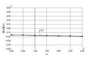
- the relational expression y (x) and the calculation result are shown in FIG.
- Table 2 shows a case where the spherical power Sph is ⁇ 4.00 dioptre (D) and the prescription addition ADD is 2.50 dioptre (D) as an example of changing the prescription addition ADD (S4). , 3.00 diopter (D) (S5), and 3.50 diopter (D) (S3) simulation values SDD and correction amount CDD are shown. Table 2 shows the parameters necessary for obtaining the simulation value SDD.
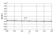
- FIG. 4 shows the relational expression y (x) and the calculation result.
- Table 3 shows that when the spherical power Sph is 0.00 diopter (D) and the prescription addition ADD is 2.50 diopter (D) (S7), and 3.00 dioptre (D) (S8). , 3.50 diopter (D) (S9) simulation value SDD and correction amount CDD are shown. It should be noted that the parameters necessary for obtaining the simulation value SDD are shown in Table 3.
- Table 4 shows that when the spherical power Sph is 4.00 diopter (D) and the prescription addition ADD is 2.50 diopter (D) (S10), and 3.00 dioptre (D) (S11). , 3.50 diopter (D) (S12) simulation value SDD and correction amount CDD are shown. Table 4 shows the parameters required for obtaining the simulation value SDD.
- Table 5 shows that when the spherical power Sph is 6.00 diopter (D) and the prescription addition ADD is 2.50 diopter (D) (S13), and 3.00 diopter (D) (S14). , 3.50 diopter (D) (S15) simulation value SDD and correction amount CDD are shown. Table 5 shows necessary parameters for obtaining the simulation value SDD.
- FIG. 7 shows the relational expression y (x) and the calculation result.
- the target addition FAD is 0.50 diopter (D)
- the change of the correction amount CDD when the prescription addition ADD is changed with respect to the representative spherical power Sph of the first refractive power D1 is S16.
- Table 6 shows that when the spherical power Sph is ⁇ 8.00 dioptre (D) and the prescription addition ADD is 1.50 diopter (D) (S16), and 2.0 dioptre (D) (S17). ), 2.50 diopter (D) (S18), 3.00 diopter (D) (S19), 3.50 diopter (D) (S20) simulation value SDD and correction amount CDD is shown. Further, parameters required for obtaining the simulation value SDD are shown in Table 6.
- Table 7 shows that the spherical power Sph is ⁇ 4.00 diopter (D), the prescription addition ADD is 1.50 diopter (D) (S21), and 2.00 diopter (D) (S22). ), 2.50 diopter (D) (S23), 3.00 diopter (D) (S24), 3.50 diopter (D) (S25) simulation value SDD and correction amount CDD is shown. It should be noted that necessary parameters for obtaining the simulation value SDD are shown in Table 7.
- FIG. 9 shows the relational expression y (x) and the calculation result.
- Table 8 shows that when the spherical power Sph is 0.00 diopter (D) and the prescription addition ADD is 1.50 diopter (D) (S26), and 2.00 diopter (D) (S27). , 2.50 diopter (D) (S28), 3.00 diopter (D) (S29), 3.50 diopter (D) (S30) simulation value SDD and correction amount CDD It is shown. Table 8 shows necessary parameters for obtaining the simulation value SDD.
- Table 9 shows that when the spherical power Sph is 4.00 diopter (D) and the prescription addition ADD is 1.50 diopter (D) (S31), and 2.00 diopter (D) (S32). , 2.50 diopter (D) (S33), 3.00 diopter (D) (S34), 3.50 diopter (D) (S35) simulation value SDD and correction amount CDD It is shown. In addition, Table 9 shows parameters necessary for obtaining the simulation value SDD.
- FIG. 11 shows the relational expression y (x) and the calculation result.
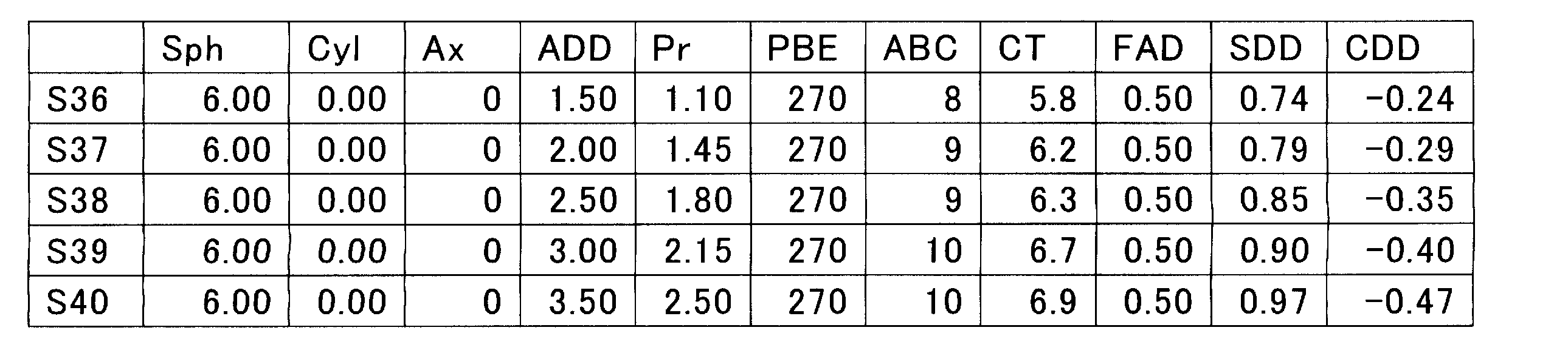
- Table 10 shows that when the spherical power Sph is 6.00 diopters (D) and the prescription addition ADD is 1.50 diopters (D) (S36), and 2.00 diopters (D) (S37). , 2.50 diopter (D) (S38), 3.00 diopter (D) (S39), 3.50 diopter (D) (S40) simulation value SDD and correction amount CDD It is shown. Table 10 shows the parameters necessary for obtaining the simulation value SDD.
- Table 11 shows that the astigmatic power Cyl is 0.00 diopter (D) (S41), -0.50 diopter (D) (S42), and -1.00 diopter (D) ( S43), -1.50 diopter (D) (S44), -2.00 diopter (D) (S45), -2.50 diopter (D) (S46), -3 Simulation value SDD and correction amount CDD when .00 diopter (D) is set (S47), -3.50 diopter (D) is set (S48), and -4.00 diopter (D) is set (S49). It is shown.
- parameters required for obtaining the simulation value SDD are shown in Table 11.
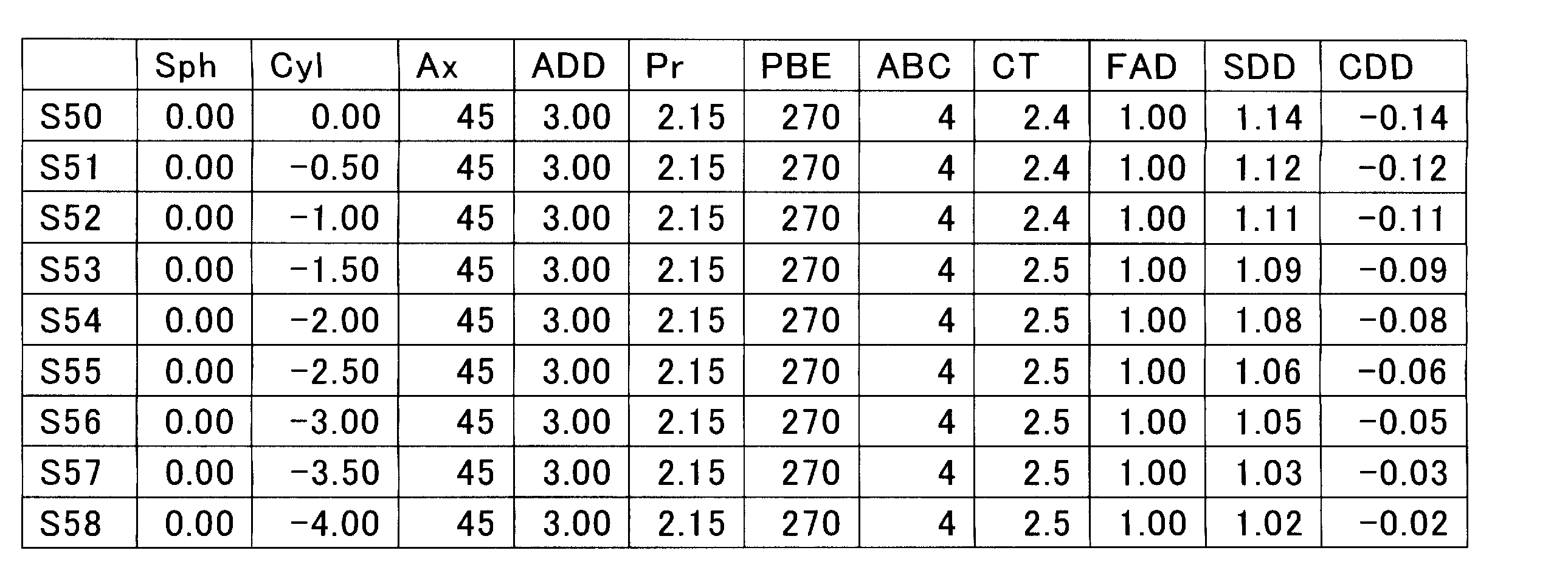
- Table 12 shows that when the astigmatism axis direction Ax is 45 ° and the astigmatism power Cyl is 0.00 diopter (D) (S50), -0.50 dioptre (D) (S51), -1. 00 diopter (D) (S52), -1.50 diopter (D) (S53), -2.00 diopter (D) (S54), -2.50 diopter (D) (S55), -3.00 diopter (D) (S56), -3.50 diopter (D) (S57), and -4.00 diopter (D) (S58). ) Shows a simulation value SDD and a correction amount CDD. In addition, Table 12 shows necessary parameters for obtaining the simulation value SDD.
- FIG. 14 shows the relational expression y (x) and the calculation result.
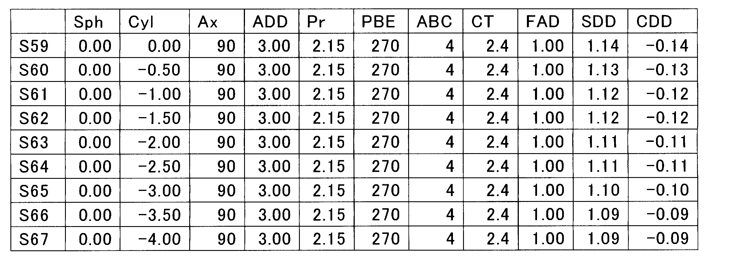
- Table 13 shows that when the astigmatic axis direction Ax is 90 ° and the astigmatism power Cyl is 0.00 diopter (D) (S59), -0.50 dioptre (D) (S60), -1. 00 diopter (D) (S61), -1.50 diopter (D) (S62), -2.00 diopter (D) (S63), -2.50 diopter (D) (S64), -3.00 diopter (D) (S65), -3.50 diopter (D) (S66), and -4.00 diopter (D) (S67). ) Shows a simulation value SDD and a correction amount CDD. In addition, parameters required for obtaining the simulation value SDD are shown in Table 13.
- FIG. 15 shows the relational expression y (x) and the calculation result.
- Table 14 shows that when the astigmatic axis direction Ax is 135 ° and the astigmatism power Cyl is 0.00 diopter (D) (S68), -0.50 dioptre (D) (S69), -1. 00 diopter (D) (S70), -1.50 diopter (D) (S71), -2.00 diopter (D) (S72), -2.50 diopter (D) (S73), -3.00 diopter (D) (S74), -3.50 diopter (D) (S75), and -4.00 diopter (D) (S76). ) Shows a simulation value SDD and a correction amount CDD. Further, parameters required for obtaining the simulation value SDD are shown in Table 14.
- Table 16 shows that when the astigmatic axis direction Ax is 45 ° and the astigmatism power Cyl is 0.00 diopter (D) (S86), -0.50 dioptre (D) (S87), -1. 00 diopter (D) (S88), -1.50 diopter (D) (S89), -2.00 diopter (D) (S90), -2.50 diopter (D) (S91), -3.00 diopter (D) (S92), -3.50 diopter (D) (S93), -4.00 diopter (D) (S94) ) Shows a simulation value SDD and a correction amount CDD. In addition, parameters required for obtaining the simulation value SDD are shown in Table 16.
- Table 17 shows that when the astigmatism axis direction Ax is 90 ° and the astigmatism power Cyl is 0.00 diopter (D) (S95), -0.50 dioptre (D) (S96), -1. 00 diopter (D) (S97), -1.50 diopter (D) (S98), -2.00 diopter (D) (S99), -2.50 diopter (D) (S100), -3.00 diopter (D) (S101), -3.50 diopter (D) (S102), -4.00 diopter (D) (S103) ) Shows a simulation value SDD and a correction amount CDD. In addition, parameters required for obtaining the simulation value SDD are shown in Table 17.
- Table 18 shows the cases where the astigmatic axis direction Ax is 135 ° and the astigmatic power Cyl is 0.00 diopter (D) (S104), -0.50 dioptre (D) (S105), and -1. 00 diopter (D) (S106), -1.50 diopter (D) (S107), -2.00 diopter (D) (S108), -2.50 diopter (D) (S109), -3.00 diopter (D) (S110), -3.50 diopter (D) (S111), -4.00 diopter (D) (S112) ) Shows a simulation value SDD and a correction amount CDD. In addition, parameters required for obtaining the simulation value SDD are shown in Table 18.
- the target addition FAD is 1.00 diopter (D)
- the change in the correction amount CDD when the prism refractive power Pr is changed with respect to the typical prism base direction PBE is based on S113 to S140.
- Table 19 shows that the prism base direction PBE is 0 ° and the prism refractive power Pr is 0.00 diopter (D) (S113), 0.50 diopter (D) (S114), and 1.00.
- diopter (D) (S115) 1.50 diopter (D) (S116), 2.00 diopter (D) (S117), 2.50 diopter (D) ( S118)
- the simulation value SDD and the correction amount CDD in the case of 3.00 diopter (D) (S119) are shown.
- parameters required for obtaining the simulation value SDD are shown in Table 19.
- FIG. 21 shows the relational expression y (x) and the calculation result.
- Table 20 shows that the prism base direction PBE is 90 ° and the prism refractive power Pr is 0.00 diopter (D) (S120), 0.50 diopter (D) (S121), 1.00.
- diopter (D) (S122), 1.50 diopter (D) (S123), 2.00 diopter (D) (S124), 2.50 diopter (D) ( S125) the simulation value SDD and the correction amount CDD in the case of 3.00 diopter (D) (S126) are shown.
- parameters required for obtaining the simulation value SDD are shown in Table 20.
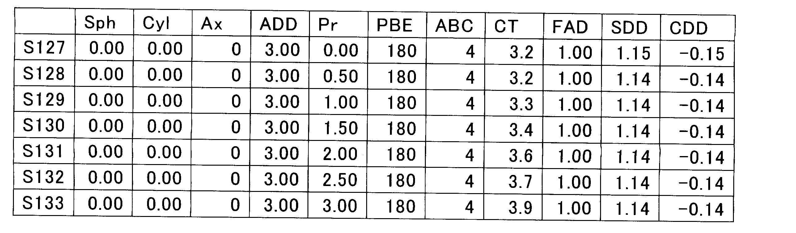
- Table 21 shows that the prism base direction PBE is 180 °, and the prism refractive power Pr is 0.00 diopter (D) (S127), 0.50 diopter (D) (S128), 1.00.
- diopter (D) S129
- 1.50 diopter D
- S130 1.50 diopter
- D S131
- 2.50 diopter D
- SDD simulation value
- parameters required for obtaining the simulation value SDD are shown in Table 23.
- Table 22 shows that the prism base direction PBE is 270 ° and the prism refractive power Pr is 0.00 diopter (D) (S134), 0.50 diopter (D) (S135), 1.00.
- diopter (D) (S136), 1.50 diopter (D) (S137), 2.00 diopter (D) (S138), 2.50 diopter (D) ( S139) the simulation value SDD and the correction amount CDD in the case of 3.00 diopter (D) (S140) are shown.
- Table 22 shows necessary parameters for obtaining the simulation value SDD.
- the target addition FAD is 0.50 diopter (D)
- the change in the correction amount CDD when the prism refractive power Pr is changed with respect to the typical prism base direction PBE is based on S141 to S168.
- Table 23 shows that the prism base direction PBE is 0 ° and the prism refractive power Pr is 0.00 diopter (D) (S141), 0.50 diopter (D) (S142), and 1.00.
- diopter (D) (S143) 1.50 diopter (D) (S144), 2.00 diopter (D) (S145), 2.50 diopter (D) ( S146)
- the simulation value SDD and the correction amount CDD in the case of 3.00 diopter (D) (S147) are shown.
- parameters required for obtaining the simulation value SDD are shown in Table 23.
- Table 24 shows that the prism base direction PBE is 90 ° and the prism refractive power Pr is 0.00 diopter (D) (S148), 0.50 diopter (D) (S149), and 1.00.
- diopter (D) (S150) 1.50 diopter (D) (S151), 2.00 diopter (D) (S152), 2.50 diopter (D) ( S153)
- the simulation value SDD and the correction amount CDD in the case of 3.00 diopter (D) (S154) are shown.
- Table 24 shows necessary parameters for obtaining the simulation value SDD.
- Table 25 shows that the prism base direction PBE is 180 ° and the prism refractive power Pr is 0.00 diopter (D) (S155), 0.50 diopter (D) (S156), 1.00.
- diopter (D) (S157), 1.50 diopter (D) (S158), 2.00 diopter (D) (S159), 2.50 diopter (D) ( S160) the simulation value SDD and the correction amount CDD in the case of 3.00 diopter (D) (S161) are shown.
- Table 25 shows necessary parameters for obtaining the simulation value SDD.
- Table 26 shows that the prism base direction PBE is 270 ° and the prism refractive power Pr is 0.00 diopter (D) (S162), 0.50 diopter (D) (S163), and 1.00.
- diopter (D) (S164) 1.50 diopter (D) (S165), 2.00 diopter (D) (S166), 2.50 diopter (D) ( S167)
- simulation value SDD and correction amount CDD in the case of 3.00 diopter (D) (S168) are shown. Further, parameters required for obtaining the simulation value SDD are shown in Table 26.
- the progressive addition lens is designed with a prescription addition ADD of 3.00 diopters (D).
- a fitting point FP is set at a position corresponding to the main meridian (the origin O of the Y axis in FIG. 1A), and the target addition FAD is set as 0.5 diopter (D).
- the surface refractive power distribution on the progressive surface (concave surface) side of the first model is shown in FIG. 29A.
- a region E1 has a refractive power of 8.00 to 8.25 diopters (D)
- a region E2 has a refractive power of 8.25 to 8.50 diopters (D)
- a region E3 has a refractive power of 8.50. ⁇ 8.75 diopters (D).
- the refractive power at the position corresponding to the fitting point FP on the main meridian is a value obtained by subtracting the target addition FAD from the first refractive power D1. 8.50 diopters (D).
- FIG. 29B the relationship between the refractive power of the eyeball side surface of the lens and the position of the main meridian is shown.
- the refractive power changes from the progressive start point PS to the progressive end point PE, and the refractive power at the position corresponding to the fitting point FP in the main meridian is 8.5 diopters (D).
- FIGS. 30A and 30B show the results of visual simulation performed on the first model shown in FIGS. 29A and 29B.
- 30A and 30B differ from FIGS. 29A and 29B in that they are viewed.
- a region F1 has a refractive power of ⁇ 7.50 to ⁇ 7.25 diopter (D)
- a region F2 has a refractive power of ⁇ 7.50 to ⁇ 7.75 diopter (D).
- the fitting point FP is in the area F2.
- FIG. 30B the relationship between refractive power and the position of the main meridian is shown.
- the simulation value of refractive power is ⁇ 7.70 diopter (D) at the position corresponding to the fitting point FP of the main meridian. This corresponds to 0.20 diopter (D) of the simulation value SDD of the addition at the position corresponding to the fitting point FP of the main meridian.
- the simulation result from the simulation apparatus 20 is acquired by the information acquisition unit 41 of the computer 30.
- the calculation unit 42 calculates a correction amount CDD from the simulation result acquired by the information acquisition unit 41 and information on the progressive power lens to be designed input through the input unit 50, and obtains a relational expression from the correction amount CDD.
- the refractive power simulation value is ⁇ 7.70 diopter (D). This translates into 0.30 diopter (D) when converted to the addition simulation value SDD, which is deficient by 0.20 diopter (D). Therefore, the correction amount CDD is 0.20 diopter (D), which is an insufficient value.
- the target addition FAD of the progressive power lens to be designed is set to 0.50 diopter (D), which is a value set in the visual simulation, but the target addition FAD of the progressive power lens to be designed is set at the time of simulation. If the value is not set, the correction amount CDD is calculated based on the relational expression.
- the correction amount CDD obtained by the control unit 44 is added to the target addition FAD and set again at a position corresponding to the fitting point FP on the main meridian to design a second model. For example, as shown in FIGS. 31A and 31B, when designing the first model, correction is made for the refractive power of 8.50 diopters (D) set as the addition on the main meridian corresponding to the fitting point FP.
- a value obtained by adding 0.2 diopter (D) of the amount CDD (8.70 diopter (D)) is reset.
- a visual simulation assuming a spectacle wearing state is performed on the first model designed by setting a target addition FAD of a desired value at a position corresponding to the fitting point FP on the main meridian, and obtained by visual simulation.
- the correction amount CDD for correcting the difference between the simulation value SDD of the addition at the position corresponding to the fitting point FP on the main meridian and the target addition FAD is calculated, and the correction amount CDD obtained by the calculation is used as the target addition power.
- the second model is designed by setting again as the addition added to the FAD, the visual simulation assuming the actual wearing state is performed on the first model, so in the final second model, The target addition FAD at the fitting point FP is less likely to deviate from the addition at the time of wearing.
- the factors that cause the added power to deviate from the set target power FAD are the size of the target power FAD, the prescription power ADD, the spherical power Sph, the astigmatic power Cyl, the astigmatic axis.
- a correction amount is obtained for each data related to these factors, so that the deviation of the target addition FAD at the fitting point from the addition during wearing is determined. Can be very small.
- FIGS. 32A and 32B a second embodiment of the present invention will be described based on FIGS. 32A and 32B.
- the same components as those in the first embodiment are denoted by the same reference numerals and the description thereof is omitted.
- the second embodiment performs the determination process after performing the simulation process, the correction amount calculation process, and the design process.
- the computer 30 of 1st Embodiment may be used from a simulation process to a design process, and another apparatus may be used.
- [Judgment process] A simulation assuming the spectacle wearing state is performed again on the second model designed in the design process. The simulation to be performed again is performed in the same process as the simulation process of the first embodiment. The results obtained in the simulation process performed again are shown in FIGS. 32A and 32B.
- the fitting point FP is at the boundary portion ( ⁇ 7.50 diopter (D)) between the region F1 and the region F2.
- the simulation value of refractive power is ⁇ 7.50 diopter (D) at the position of the main meridian where the fitting point FP is set (origin 0).
- the re-simulation value ( ⁇ 7.50 diopter (D)) obtained in the re-executed simulation process matches the refractive power ( ⁇ 7.50 diopter (D)) set as the target addition FAD. It will be. This completes the design process.
- the determination process when it is determined that the re-simulation value does not match the desired value based on the target addition FAD, the design process is performed again, and the determination process is performed again.
- the simulation process assuming the spectacle wearing state is performed again on the second model designed in the design process, and the re-simulation value obtained in the simulation process and the target addition FAD are calculated. Since it is determined whether or not the desired value is based on this, it is possible to confirm whether or not the correction of the progressive-power lens after the design is correctly performed.
- the present invention is not limited to the above-described embodiments, and modifications, improvements, and the like within the scope that can achieve the object of the present invention are included in the present invention.
- the main meridian C is set on the Y axis along the top and bottom corresponding to the first region 1A.
- the main meridian C is linearly formed along the Y axis over the first region 1A, the intermediate region 1C, and the second region 1B. You may do it.
- the line segment along the top and bottom of the main meridian is not limited to the one set on the Y axis, and may be separated from the Y axis in the X axis direction and parallel to the Y axis.
- the progressive addition lens 1 designed in each embodiment has a progressive surface on the eyeball side and a spherical surface on the object side.
- both the eyeball side and the object side are designed as progressive surfaces. It can also be applied to things.
- a relational expression indicating the relationship between the correction amount and the parameter obtained for each simulation executed a plurality of times is obtained by the calculation process, and the design process is performed. It is also possible to set the addition power at the position corresponding to the fitting point FP on the main meridian based on the relational expression obtained in the calculation process. In the present invention, it is not always necessary to obtain the relational expression.
- SYMBOLS 1 ... Progressive-power lens, 10 ... Progressive-power lens design apparatus, 1A ... 1st area
Landscapes
- Physics & Mathematics (AREA)
- Health & Medical Sciences (AREA)
- Ophthalmology & Optometry (AREA)
- General Physics & Mathematics (AREA)
- Engineering & Computer Science (AREA)
- Optics & Photonics (AREA)
- General Health & Medical Sciences (AREA)
- Theoretical Computer Science (AREA)
- Computer Hardware Design (AREA)
- Evolutionary Computation (AREA)
- Geometry (AREA)
- General Engineering & Computer Science (AREA)
- Eyeglasses (AREA)
Abstract
Description
従来の累進屈折力レンズとして、レンズのほぼ中央を通る主子午線に沿って、曲率半径が累進的に変化する累進帯を持ち、主子午線上の遠用中心と近用中心との間で所定の加入度が付加される眼鏡レンズがある(特許文献1)。
特許文献1の従来例では、使用者毎に処方した加入度(処方加入度)にかかわらず、フッティングポイントにおいて、目的加入度として約0.5ディオプトリーの屈折力が遠用屈折力に対して付加されているため、使用者の処方加入度によらず、目標距離として設定した約2m先を明視することができる。
しかし、設計された累進屈折力レンズを実際に装用すると、目的加入度に対してずれるという課題がある。
目視シミュレーションを実施した後、フィッティングポイントにおける加入度のシミュレーション値と目的加入度との差を補正する補正量を演算し、この補正量を当初の目的加入度に付加した加入度をフィッティングポイントに再度設定して第二モデルを設計する。
そのため、本発明では、第一モデルに対して実際の装用状態を想定した目視シミュレーションを実施しているので、第二モデルにおいては、フィッティングポイントにおける目的加入度が装用時の加入度に対してずれることが少ない。
この構成では、累進屈折力レンズを実際に装用した場合の加入度が設定した目的加入度に対してずれる要因が、目的加入度の大きさ、処方加入度、球面度数、乱視度数、乱視軸方向、プリズム屈折力及びプリズム基底方向の要因に関係することに鑑み、これらの要因に関するデータ毎に補正量を求めておく。そして、これらのデータから適切な補正量を求める。
そのため、フィッティングポイントにおける目的加入度が装用時の加入度に対してずれる量を極めて小さなものにできる。
この構成では、判定工程により、設計した後の累進屈折力レンズの補正が正しく実施できているか否かを確認することができる。仮に、補正が正しく実施されていない場合には、設計工程を再度実施することで、フィッティングポイントにおける目的加入度の装用時の加入度に対するずれを確実に小さなものにできる。
この構成では、使用者の処方加入度によらず、目標距離として設定した場所を明視することができるレンズにおいて、前述と同様の効果を奏することができる。
本発明では、前述と同様の効果を奏する累進屈折力レンズの設計装置を実現することができる。
[累進屈折力レンズ]
図1Aには、累進屈折力レンズの正面が示されている。
図1Aに示される通り、累進屈折力レンズ1は、第一屈折力D1を付与する第一領域1Aと、第二屈折力D2を付与する第二領域1Bと、第一領域1A及び第二領域1Bの間に配置される中間領域1Cと、中間領域1Cの両側に配置される側方領域1Dとを有する。
第一領域1Aは、遠用視をするための領域であり、第二領域1Bは、近用視をするための領域である。中間領域1Cは、加入度が連続して変化する累進領域である。
主子午線Cは、累進屈折力レンズを装用した状態で遠方視から近方視をする際(レンズの上方から下方に視線を移動させる際)に、視線が通過する頻度が最も高いレンズ上の位置に沿う線である。本実施形態で設計される累進屈折力レンズ1は、眼球側が累進面とされ、物体側が球面とされている。
主子午線Cの上であって中間領域1Cの第一領域1Aに近接する位置には累進開始点PSが設定され、第二領域1Bに近接する位置には累進終了点PEが設定されている。
第一領域1Aには、第一領域1Aで付与される第一屈折力の大きさを測定する第一測定基準点P1が設定されている。第一測定基準点P1は主子午線上であって累進開始点PSの上方近傍に設定されている。例えば、第一測定基準点P1は第一屈折力測定参照円(図示せず)の中心に位置し、第一屈折力測定参照円の円弧部分に累進開始点PSが一致するようにしてもよい。
第二領域1Bには、第二領域1Bで付与される第二屈折力の大きさを測定する第二測定基準点P2が設定されている。第二測定基準点P2は主子午線C上であって累進終了点PEの下方近傍に設定されている。例えば、第二測定基準点P2は第一屈折力測定参照円(図示せず)の中心に位置し、第一屈折力測定参照円の円弧部分に累進終了点PEが一致することにしてもよい。
フィッティングポイントFPは、図1Aでは、原点Oより第一領域1A側に設定されているが、原点Oと一致してもよく、あるいは、原点Oより第二領域1B側に設定されているものでもよい。
図1Bに示される通り、主子午線Cのうち線部C1の屈折力は、第一領域1Aから累進開始点PSにかけて第一屈折力D1ディオプトリーであり、線部C3の累進開始点PSから累進終了点PEにかけてD1ディオプトリーからD2ディオプトリーに増加し、線部C2の累進終了点PEから第二領域1Bの下部にかけてD2ディオプトリーのままとされる。
累進開始点PSと累進終了点PEとの間の加入度の差は、装用者の処方により設定される処方加入度ADDであり、ADD=D2-D1である。
目的距離がdである場合には、目的加入度FADは(1/d)である。例えば、目標距離dが1.0mである場合には、目的加入度FADは、1/1.0(m)=1.0(ディオプトリー(D))となり、目標距離dが2.0mである場合には、目的加入度FADは、1/2.0(m)=0.5(ディオプトリー(D))となる。
累進開始点PSとフィッティングポイントFPとの間の加入度の平均勾配Mと、フィッティングポイントFPと累進終了点PEとの間の加入度の平均勾配Nとが異なるように設定する。これにより、フィッティングポイントFPでの遠点を固定できるため、処方加入度ADDによらず目標距離を明視することが可能となる。
図2には、第1実施形態の累進屈折力レンズの設計装置10の概略が示されている。
図2において、設計装置10は、シミュレーション装置20及びコンピュータ30を備える。
シミュレーション装置20は、フィッティングポイントFPにおいて目標距離dに対応する目的加入度FADを設定して設計された第一モデル(図示せず)に対して、眼鏡装用状態を想定した目視シミュレーションを実施するものであり、目視シミュレーションの実施にあたり、公知の光線追跡法が用いられる。
光線追跡法は、レンズの対物側面に入射した光線がどのようなルートを辿ってレンズの眼球側の面から出てきてどこに集光するかを計算するものであり、本実施形態では、光線追跡法を利用して、第一モデルのフィッティングポイントFPにおける加入度のシミュレーション値SDDを演算する。
ここで、パラメータには、目的加入度FAD、処方加入度ADD、第一屈折力D1を付与する第一領域1Aの球面度数Sph、乱視度数Cyl、乱視軸方向Ax、プリズム屈折力Pr、プリズム基底方向PBE、凸面カーブABC、レンズ中心厚さCTであり、レンズ情報とは、レンズの屈折率n、フィッティングポイントFP、累進開始点PS、累進終了点PE、第一測定基準点P1及び第二測定基準点P2のそれぞれの位置、その他である。
目視シミュレーションは、所定のパラメータを選択し、選択したパラメータの値を代えて複数回実施される。
入力部50は、設計対象となる累進屈折力レンズの種々の情報を入力するものであり、入力手段としては、キーボード、その他、パーソナルコンピュータにおける入力手段を例示できる。
入力部50を通じて入力される入力データは、目的加入度FAD、処方加入度ADD、第一屈折力D1を付与する第一領域1Aの球面度数Sph、乱視度数Cyl、乱視軸方向Ax、プリズム屈折力Pr、プリズム基底方向PBE、凸面カーブABC、レンズ中心厚さCTであり、レンズ情報とは、レンズの屈折率n、フィッティングポイントFP、累進開始点PS、累進終了点PE、第一測定基準点P1及び第二測定基準点P2のそれぞれの位置、その他のレンズ設計で必要とされる情報である。
情報取得部41は、シミュレーション装置20から出力されるフィッティングポイントFPにおける加入度のシミュレーション値SDDとシミュレーションで変化させたパラメータの値とを取得する。
演算部42は、情報取得部41で取得された情報に基づいてフィッティングポイントFPにおける加入度のシミュレーション値SDDと入力部50で入力された目的加入度FADとの差を補正量CDDとしてシミュレーション毎に演算する補正量演算部421と、補正量演算部421からのデータに基づいてシミュレーション毎に求められる補正量CDDとシミュレーションで変化させたパラメータの値との関係を示す関係式を演算する関係式演算部422とを有する。
基本情報データベース433は、例えば、累進開始点PSの位置、累進終了点PEの位置、フィッティングポイントFPの位置、その他レンズを設計するために必要な基本情報を記憶するものである。
制御部44は、入力部50で入力された実際に設計するためのレンズの情報と記憶部43で記憶された情報とを照合し、第二モデルを設計するための補正量CDDを求める。
設計部45は、制御部44で求められた補正量CDDを第一モデルで設定した目的加入度FADに付加して図示しない第二モデルを設計する。
設計された第二モデルは、図示しないディスプレイで表示され、あるいは、図示しない印刷装置で印刷される。
まず、目的加入度FADが1.00ディオプトリー(D)であり、第一屈折力D1の代表的な球面度数Sphに対して、処方加入度ADDを変えた場合の補正量CDDの変化をS1からS15に基づいて説明する。
表1には、球面度数Sphを-8.00ディオプトリー(D)とし、処方加入度ADDを2.50ディオプトリー(D)とした場合(S1)、3.00ディオプトリー(D)とした場合(S2)、3.50ディオプトリー(D)とした場合(S3)のシミュレーション値SDD及び補正量CDDが示されている。シミュレーション値SDDは、主子午線上のフィッティングポイントFPに対応する位置における加入度の大きさである。なお、表では、シミュレーション値SDDと補正量CDDとは、それぞれ小数点3以下を四捨五入して表示している。以下の例も同様である。シミュレーション値SDDを求めるにあたり、必要なパラメータは表1に示されている。

y=-0.0052x2 + 0.0226x + 0.2206
であり、この関係式y(x)と演算結果が図3で示されている。

y=-0.0031x2 - 0.0128x + 0.1449
であり、この関係式y(x)と演算結果が図4で示されている。

y=-0.0055x2 - 0.032x + 0.0088
であり、この関係式y(x)と演算結果が図5で示されている。

y=-0.0809x2 + 0.399x - 0.7505
であり、この関係式y(x)と演算結果が図6で示されている。

y=-0.0714x2 + 0.3188x - 0.6673
であり、この関係式y(x)と演算結果が図7で示されている。
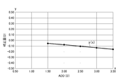
表6には、球面度数Sphを-8.00ディオプトリー(D)とし、処方加入度ADDを1.50ディオプトリー(D)とした場合(S16)、2.0ディオプトリー(D)とした場合(S17)、2.50ディオプトリー(D)とした場合(S18)、3.00ディオプトリー(D)とした場合(S19)、3.50ディオプトリー(D)とした場合(S20)のシミュレーション値SDD及び補正量CDDが示されている。
また、シミュレーション値SDDを求めるにあたり、必要なパラメータは表6に示されている。

y= 0.0004x2 - 0.0065x + 0.2338
であり、この関係式y(x)と演算結果が図8で示されている。
なお、シミュレーション値SDDを求めるにあたり、必要なパラメータは表7に示されている。

y= 0.0027x2 - 0.0373x + 0.1521
であり、この関係式y(x)と演算結果が図9で示されている。

y= 0.0012x2 - 0.0608x + 0.0428
であり、この関係式y(x)と演算結果が図10で示されている。

y= -0.0073x2 - 0.0553x - 0.0864
であり、この関係式y(x)と演算結果が図11で示されている。
なお、シミュレーション値SDDを求めるにあたり、必要なパラメータは表10に示されている。
y= -0.0051x2 - 0.088x - 0.0974
であり、この関係式y(x)と演算結果が図12で示されている。
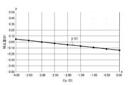
表11には、乱視度数Cylを0.00ディオプトリー(D)とした場合(S41)、-0.50ディオプトリー(D)とした場合(S42)、-1.00ディオプトリー(D)とした場合(S43)、-1.50ディオプトリー(D)とした場合(S44)、-2.00ディオプトリー(D)とした場合(S45)、-2.50ディオプトリー(D)とした場合(S46)、-3.00ディオプトリー(D)とした場合(S47)、-3.50ディオプトリー(D)とした場合(S48)、-4.00ディオプトリー(D)とした場合(S49)のシミュレーション値SDD及び補正量CDDが示されている。また、シミュレーション値SDDを求めるにあたり、必要なパラメータは表11に示されている。

y= 0.0001x2 - 0.0464x - 0.1359
であり、この関係式y(x)と演算結果が図13で示されている。
また、シミュレーション値SDDを求めるにあたり、必要なパラメータは表12に示されている。
y= -0.0003x2 - 0.0308x - 0.1364
であり、この関係式y(x)と演算結果が図14で示されている。
また、シミュレーション値SDDを求めるにあたり、必要なパラメータは表13に示されている。
y= -0.0002x2 - 0.0127x - 0.1367
であり、この関係式y(x)と演算結果が図15で示されている。
また、シミュレーション値SDDを求めるにあたり、必要なパラメータは表14に示されている。

y= -0.0006x2 - 0.0268x - 0.1367
であり、この関係式と演算結果が図16で示されている。
表15には、乱視軸方向Axを0°とし、乱視度数Cylを0.00ディオプトリー(D)とした場合(S77)、-0.50ディオプトリー(D)とした場合(S78)、-1.00ディオプトリー(D)とした場合(S79)、-1.50ディオプトリー(D)とした場合(S80)、-2.00ディオプトリー(D)とした場合(S81)、-2.50ディオプトリー(D)とした場合(S82)、-3.00ディオプトリー(D)とした場合(S83)、-3.50ディオプトリー(D)とした場合(S84)、-4.00ディオプトリー(D)とした場合(S85)のシミュレーション値SDD及び補正量CDDが示されている。また、シミュレーション値SDDを求めるにあたり、必要なパラメータは表15に示されている。

y= 1.0×10-05x2 - 0.0385x - 0.1275
であり、この関係式y(x)と演算結果が図17で示されている。
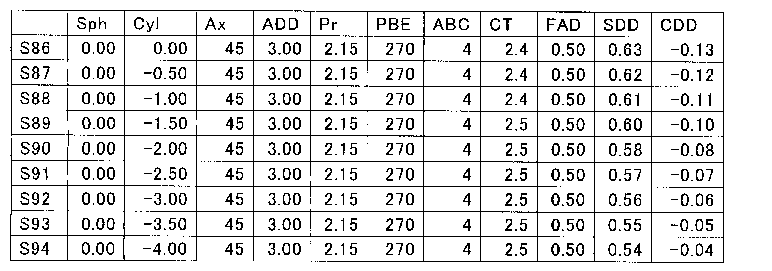
y = 0.0003x2 - 0.0214x - 0.128
であり、この関係式y(x)と演算結果が図18で示されている。
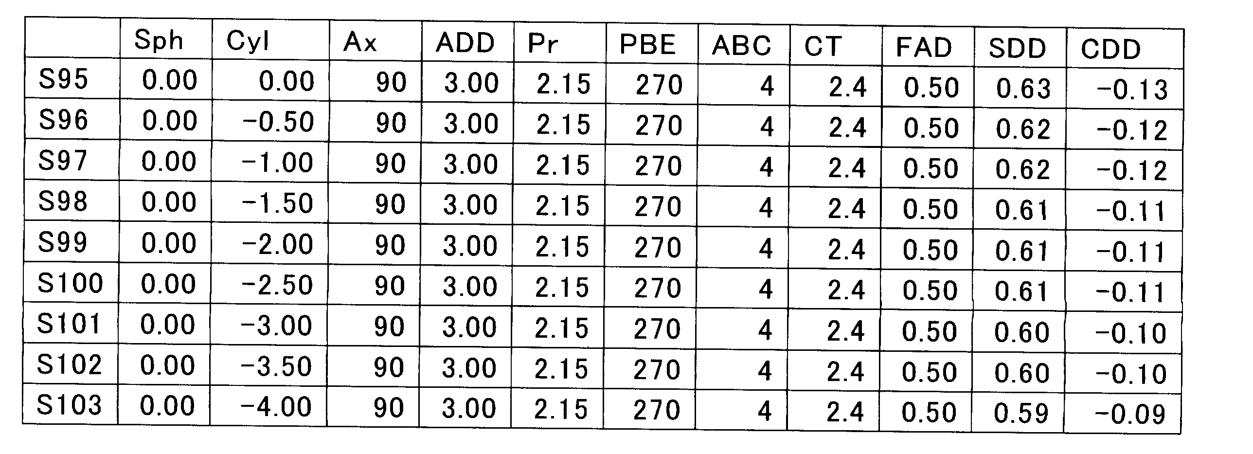
y= -0.0002x2 - 0.0127x - 0.1367
であり、この関係式y(x)と演算結果が図19で示されている。

y= -0.0006x2 - 0.0268x - 0.1367
であり、この関係式y(x)と演算結果が図20で示されている。
表19には、プリズム基底方向PBEを0°とし、プリズム屈折力Prを0.00ディオプトリー(D)とした場合(S113)、0.50ディオプトリー(D)とした場合(S114)、1.00ディオプトリー(D)とした場合(S115)、1.50ディオプトリー(D)とした場合(S116)、2.00ディオプトリー(D)とした場合(S117)、2.50ディオプトリー(D)とした場合(S118)、3.00ディオプトリー(D)とした場合(S119)のシミュレーション値SDD及び補正量CDDが示されている。また、シミュレーション値SDDを求めるにあたり、必要なパラメータは表19に示されている。
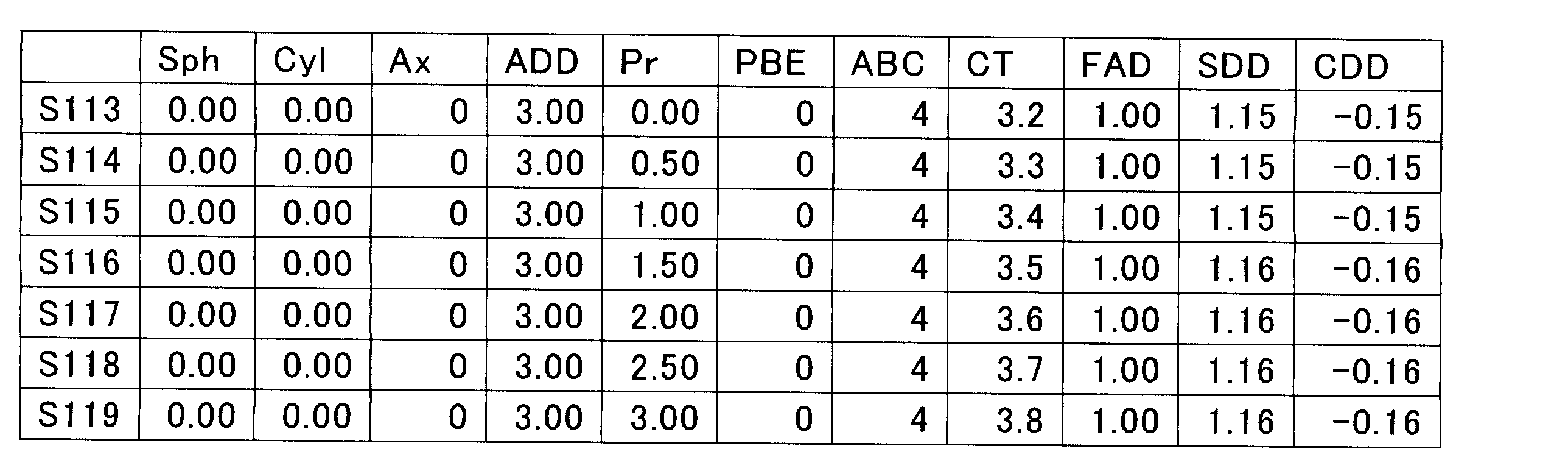
y= 0.0007x2 - 0.0079x - 0.147
であり、この関係式y(x)と演算結果が図21で示されている。

y= 0.0009x2 - 0.0044x - 0.1468
であり、この関係式y(x)と演算結果が図22で示されている。
y= 0.0009x2 - 0.0044x - 0.1468
であり、この関係式y(x)と演算結果が図23で示されている。

y= 0.0009x2 - 0.0044x - 0.1468
であり、この関係式y(x)と演算結果が図24で示されている。
表23には、プリズム基底方向PBEを0°とし、プリズム屈折力Prを0.00ディオプトリー(D)とした場合(S141)、0.50ディオプトリー(D)とした場合(S142)、1.00ディオプトリー(D)とした場合(S143)、1.50ディオプトリー(D)とした場合(S144)、2.00ディオプトリー(D)とした場合(S145)、2.50ディオプトリー(D)とした場合(S146)、3.00ディオプトリー(D)とした場合(S147)のシミュレーション値SDD及び補正量CDDが示されている。また、シミュレーション値SDDを求めるにあたり、必要なパラメータは表23に示されている。

y= 0.0006x2 - 0.0075x - 0.1568
であり、この関係式y(x)と演算結果が図25で示されている。

y= 0.0011x2 - 0.0132x - 0.1566
であり、この関係式y(x)と演算結果が図26で示されている。

y= 0.0011x2 - 0.0132x - 0.1566
であり、この関係式y(x)と演算結果が図27で示されている。

y = 0.0011x2 - 0.0132x - 0.1566
であり、この関係式y(x)と演算結果が図28で示されている。
[第一モデル]
第一モデルを設計する。第一モデルでは、レンズの眼球側面(凹面)の面度数をコントロールするものである。なお、レンズの物体側面(凸面)は球面である。
例えば、第一モデルを、球面度数Sphを-8.00ディオプトリー(D)とし、第一屈折力D1を9.00ディオプトリー(D)とし、第二屈折力D2を6.00ディオプトリー(D)とし、処方加入度ADDを3.00ディオプトリー(D)として累進屈折力レンズを設計する。主子午線に対応する位置(図1AのY軸の原点O)にフィッティングポイントFPを設定し、目的加入度FADを0.5ディオプトリー(D)として設定する。第一モデルの累進面(凹面)側の面屈折力分布が図29Aに示される。
図29Bにおいて、レンズの眼球側面の屈折力と主子午線の位置との関係が示されている。図29Bにおいて、累進開始点PSから累進終了点PEにかけて屈折力が変化しており、主子午線のうちフィッティングポイントFPに対応する位置での屈折力は、8.5ディオプトリー(D)である。
フィッティングポイントFPにおいて目的加入度FADを設定して設計された第一モデルに対して、眼鏡装用状態を想定した目視シミュレーションをシミュレーション装置20で実施する。
シミュレーション装置20は、目視シミュレーションを、表1から表28に示される通り、パラメータを変えて複数実施し、その結果をコンピュータ30に出力する。
例えば、図29Aおよび図29Bで示される第一モデルに対して、目視シミュレーションをした結果を図30Aおよび図30Bに示す。図30Aおよび図30Bは図29Aおよび図29Bとは異なり、目視した状態を示す。
図30Bにおいて、屈折力と主子午線の位置との関係が示されている。図30Bにおいて、主子午線のフィッティングポイントFPに対応する位置において、屈折力のシミュレーション値が-7.70ディオプトリー(D)である。これは、主子午線のフィッティングポイントFPに対応する位置における加入度のシミュレーション値SDDの0.20ディオプトリー(D)に相当する。
シミュレーション装置20からのシミュレーション結果をコンピュータ30の情報取得部41で取得する。
演算部42では、情報取得部41で取得したシミュレーション結果と、入力部50を通じて入力された設計対象の累進屈折力レンズの情報とから補正量CDDを演算し、補正量CDDから関係式を求める。
演算部42で演算された結果に基づいて、パラメータと補正量との関係、及びパラメータと関係式との関係を記憶部43で記憶する。
[設計工程]
入力部50で設計対象の累進屈折力レンズのパラメータを入力すると、制御部44では、入力部50から入力された情報と記憶部43で記憶された情報とから第二モデルを設計するための補正量が求められる。
例えば、図29Aおよび図29Bの累進屈折力レンズを設計する場合では、第一屈折力が-8.00ディオプトリー(D)であり、目的加入度FADが0.50ディオプトリー(D)であるため、設計上では、屈折力は-7.50ディオプトリー(D)となる。しかし、図30Aおよび図30Bに示される通り、目視シミュレーションをした結果、屈折力のシミュレーション値は-7.70ディオプトリー(D)である。これは、加入度のシミュレーション値SDDに変換すると、0.30ディオプトリー(D)であり、0.20ディオプトリー(D)だけ不足していることになる。そのため、補正量CDDは、不足した値である0.20ディオプトリー(D)となる。
制御部44で求められた補正量CDDを目的加入度FADに付加し主子午線上のフィッティングポイントFPに対応する位置に再度設定して第二モデルを設計する。
例えば、図31Aおよび図31Bに示される通り、第一モデルを設計する際に、フィッティングポイントFPに対応する主子午線上の加入度として設定した屈折力8.50ディオプトリー(D)に対して、補正量CDDの0.2ディオプトリー(D)を付加した値(8.70ディオプトリー(D))を再設定する。
主子午線上のフィッティングポイントFPに対応する位置において所望値の目的加入度FADを設定して設計された第一モデルに対して、眼鏡装用状態を想定した目視シミュレーションを実施し、目視シミュレーションで得られた主子午線上のフィッティングポイントFPに対応する位置における加入度のシミュレーション値SDDと目的加入度FADとの差を補正する補正量CDDを演算し、演算して得られた補正量CDDを目的加入度FADに付加した加入度として再度設定して第二モデルを設計するから、第一モデルに対して実際の装用状態を想定した目視シミュレーションを実施しているので、最終的な第二モデルにおいては、フィッティングポイントFPにおける目的加入度FADが装用時の加入度に対してずれることが少ない。
次に、本発明の第2実施形態を図32Aおよび図32Bに基づいて説明する。第2実施形態の説明において、第1実施形態と同一構成要素は同一符号を付して説明を省略する。
第2実施形態は、第1実施形態と同様に、シミュレーション工程、補正量演算工程及び設計工程を実施した後に、判定工程を実施する。なお、シミュレーション工程から設計工程までを第1実施形態のコンピュータ30を用いてもよく、別の装置を用いてもよい。
[判定工程]
設計工程で設計された第二モデルに対して、眼鏡装用状態を想定したシミュレーションを再度実施する。
再度実施するシミュレーションは、第1実施形態のシミュレーション工程と同様の工程で実施される。
再度実施されたシミュレーション工程で得られた結果を図32Aおよび図32Bに示す。
図32Bにおいて、フィッティングポイントFPが設定される主子午線の位置(原点0)において、屈折力のシミュレーション値が-7.50ディオプトリー(D)である。
なお、判定工程で、再シミュレーション値と目的加入度FADに基づく所望値とが一致しないと判定した場合には、設計工程を再度実施し、判定工程を再度実施する。
例えば、各実施形態では、視線が近方視の時の輻輳により鼻側に内寄せされることを考慮して、主子午線Cを、第一領域1Aに対応し上下に沿ったY軸の上に設定される線部C1と、第二領域1Bに対応しY軸からX軸方向に寸法Iだけ離れかつY軸と平行に設定される線部C2と、中間領域1Cに対応し累進開始点PSと累進終了点PEとを結ぶ線部C3とから構成したが、本発明では、主子午線Cを、第一領域1A、中間領域1C及び第二領域1BにかけてY軸に沿って直線状に形成するものでもよい。さらに、主子午線の上下に沿った線分はY軸の上に設定されるものに限定されるものではなく、Y軸からX軸方向に離れかつY軸と平行とされるものでもよい。
また、本発明では、図3から図28の実施例で示される通り、演算工程により、複数回実施されるシミュレーション毎に求められる補正量とパラメータとの関係を示す関係式を求め、設計工程において、演算工程で求められた関係式に基づいて主子午線上のフィッティングポイントFPに対応する位置での加入度を設定することも可能である。また、本発明では、関係式を必ずしも求めることを要しない。
Claims (5)
- 第一屈折力を付与する第一領域と第二屈折力を付与する第二領域との間に加入度が連続して変化する中間領域を設け、前記第一領域、前記中間領域及び前記第二領域に主子午線を設け、前記中間領域の前記第一領域に近接する部分に前記主子午線が通る累進開始点を設定し、前記中間領域の第二領域に近接する部分に前記主子午線が通る累進終了点を設定し、前記累進開始点と前記累進終了点との間にあって前記主子午線のうち前記第一領域を通る部分の延長線に沿った位置にフィッティングポイントを設定する累進屈折力レンズの設計方法であって、
前記主子午線上の前記フィッティングポイントに対応する位置において所望値の目的加入度を設定して設計された第一モデルに対して、眼鏡装用状態を想定した目視シミュレーションを実施するシミュレーション工程と、
前記シミュレーション工程で得られた前記主子午線上の前記フィッティングポイントに対応する位置における加入度のシミュレーション値と前記目的加入度との差を補正する補正量を演算する演算工程と、
前記演算工程で求められた前記補正量を前記目的加入度に付加した加入度として前記主子午線上の前記フィッティングポイントに対応する位置に再度設定して第二モデルを設計する設計工程と、を備えた
ことを特徴とする累進屈折力レンズの設計方法。 - 請求項1に記載された累進屈折力レンズの設計方法において、
前記シミュレーション工程は、前記第一モデルの前記目的加入度、前記第一屈折力と前記第二屈折力との差で規定される処方加入度、前記第一屈折力を付与する領域の球面度数、乱視度数、乱視軸方向、プリズム屈折力及びプリズム基底方向のすくなくとも一つのパラメータの数値を代えて複数回実施し、
前記演算工程は、前記シミュレーション毎に前記補正量を演算し、
前記設計工程は、予め記憶された前記目的加入度、前記処方加入度、前記球面度数、前記乱視度数、前記乱視軸方向、前記プリズム屈折力及び前記プリズム基底方向のすくなくとも一つと前記補正量との関係に基づいて前記第二モデルを設計するための前記主子午線上の前記フィッティングポイントに対応する位置での加入度を設定する
ことを特徴とする累進屈折力レンズの設計方法。 - 請求項1に記載された累進屈折力レンズの設計方法において、
前記設計工程の後に、前記眼鏡装用状態を想定したシミュレーションを再度実施し再シミュレーション値と前記所望値との差に基づいて前記再シミュレーション値と前記所望値とが一致するか否かを判定する判定工程を備え、
前記判定工程で、前記再シミュレーション値と前記所望値とが一致しないと判定した場合には、前記設計工程を再度実施する
ことを特徴とする累進屈折力レンズの設計方法。 - 請求項1ないし請求項3のいずれか1項に記載された累進屈折力レンズの設計方法において、
前記フィッティングポイントは、前記累進開始点と前記累進終了点との間にあって前記主子午線のうち前記第一領域を通る部分の延長線に沿った位置に設定され、
前記目的加入度は、装用者が明確に視認したい目的位置までの目標距離に応じて設定され、前記累進開始点と前記フィッティングポイントとの間の加入度の平均勾配と、前記フィッティングポイントと前記累進終了点との間の加入度の平均勾配とが異なるように設定する
ことを特徴とする累進屈折力レンズの設計方法。 - 第一屈折力を付与する第一領域と第二屈折力を付与する第二領域との間に加入度が連続して変化する中間領域が設けられ、前記第一領域、前記中間領域及び前記第二領域に主子午線が設けられ、前記中間領域の前記第一領域に近接する部分に前記主子午線が通る累進開始点が設定され、前記中間領域の第二領域に近接する部分に前記主子午線が通る累進終了点が設定され、前記累進開始点と前記累進終了点との間にあって前記主子午線のうち前記第一領域を通る部分の延長線に沿った位置にフィッティングポイントが設定される累進屈折力レンズを設計する装置であって、
前記主子午線上の前記フィッティングポイントに対応する位置において所望値の目的加入度を設定して設計された第一モデルに対して、眼鏡装用状態を想定した目視シミュレーションを、前記第一モデルの前記目的加入度、前記第一屈折力と前記第二屈折力との差で規定される処方加入度、前記第一屈折力を付与する領域の球面度数、乱視度数、乱視軸方向、プリズム屈折力及びプリズム基底方向のすくなくとも一つのパラメータを代えて複数回実施するシミュレーション装置と、
前記シミュレーション装置で得られた結果に基づいて累進屈折力レンズを設計するコンピュータと、を備え、
前記コンピュータは、前記シミュレーション装置からの情報に基づいて前記フィッティングポイントにおける加入度のシミュレーション値と前記目的加入度との差を補正する補正量をシミュレーション毎に演算する演算部と、
前記演算部で演算された結果に基づいて、前記目的加入度、前記処方加入度、前記球面度数、前記乱視度数、前記乱視軸方向、前記プリズム屈折力及び前記プリズム基底方向のすくなくとも一つと前記補正量との関係を記憶する記憶部と、
前記目的加入度、前記処方加入度、前記球面度数、前記乱視度数、前記乱視軸方向、前記プリズム屈折力及び前記プリズム基底方向のすくなくとも一つの情報を入力する入力部と、
前記入力部から入力にされた情報と前記記憶部で記憶された情報とから第二モデルを設計するための前記補正量を求める制御部と、
前記制御部で求められた前記補正量を前記目的加入度に付加し前記主子午線上の前記フィッティングポイントに対応する位置に再度設定して前記第二モデルを設計する設計部と、
を有する
ことを特徴とする累進屈折力レンズの設計装置。
Priority Applications (4)
| Application Number | Priority Date | Filing Date | Title |
|---|---|---|---|
| CN201680030205.1A CN107615280B (zh) | 2015-05-26 | 2016-05-26 | 渐进屈光力镜片的设计方法及设计装置 |
| EP16800096.6A EP3306499A4 (en) | 2015-05-26 | 2016-05-26 | DESIGN PROCESS AND DESIGN DEVICE FOR OPTIC LIGHT GLASS |
| US15/576,266 US10545354B2 (en) | 2015-05-26 | 2016-05-26 | Designing method and designing device for progressive power lens |
| JP2017520804A JP6496019B2 (ja) | 2015-05-26 | 2016-05-26 | 累進屈折力レンズの設計方法及び設計装置 |
Applications Claiming Priority (2)
| Application Number | Priority Date | Filing Date | Title |
|---|---|---|---|
| JP2015-106887 | 2015-05-26 | ||
| JP2015106887 | 2015-05-26 |
Publications (1)
| Publication Number | Publication Date |
|---|---|
| WO2016190392A1 true WO2016190392A1 (ja) | 2016-12-01 |
Family
ID=57393916
Family Applications (1)
| Application Number | Title | Priority Date | Filing Date |
|---|---|---|---|
| PCT/JP2016/065598 Ceased WO2016190392A1 (ja) | 2015-05-26 | 2016-05-26 | 累進屈折力レンズの設計方法及び設計装置 |
Country Status (5)
| Country | Link |
|---|---|
| US (1) | US10545354B2 (ja) |
| EP (1) | EP3306499A4 (ja) |
| JP (1) | JP6496019B2 (ja) |
| CN (1) | CN107615280B (ja) |
| WO (1) | WO2016190392A1 (ja) |
Cited By (1)
| Publication number | Priority date | Publication date | Assignee | Title |
|---|---|---|---|---|
| CN111358421A (zh) * | 2020-03-16 | 2020-07-03 | 深圳盛达同泽科技有限公司 | 屈光图形生成方法、装置及计算机可读存储介质 |
Families Citing this family (10)
| Publication number | Priority date | Publication date | Assignee | Title |
|---|---|---|---|---|
| CN107615138B (zh) * | 2015-05-26 | 2019-06-14 | 豪雅镜片泰国有限公司 | 渐进屈光力镜片的设计方法及镜片组 |
| US12121300B2 (en) | 2018-05-20 | 2024-10-22 | Neurolens, Inc. | Method of operating a progressive lens simulator with an axial power-distance simulator |
| US11175518B2 (en) | 2018-05-20 | 2021-11-16 | Neurolens, Inc. | Head-mounted progressive lens simulator |
| US10783700B2 (en) | 2018-05-20 | 2020-09-22 | Neurolens, Inc. | Progressive lens simulator with an axial power-distance simulator |
| US11559197B2 (en) | 2019-03-06 | 2023-01-24 | Neurolens, Inc. | Method of operating a progressive lens simulator with an axial power-distance simulator |
| US11259697B2 (en) | 2019-03-07 | 2022-03-01 | Neurolens, Inc. | Guided lens design exploration method for a progressive lens simulator |
| US11241151B2 (en) | 2019-03-07 | 2022-02-08 | Neurolens, Inc. | Central supervision station system for Progressive Lens Simulators |
| US11288416B2 (en) | 2019-03-07 | 2022-03-29 | Neurolens, Inc. | Deep learning method for a progressive lens simulator with an artificial intelligence engine |
| US11259699B2 (en) | 2019-03-07 | 2022-03-01 | Neurolens, Inc. | Integrated progressive lens simulator |
| US11202563B2 (en) | 2019-03-07 | 2021-12-21 | Neurolens, Inc. | Guided lens design exploration system for a progressive lens simulator |
Citations (3)
| Publication number | Priority date | Publication date | Assignee | Title |
|---|---|---|---|---|
| JP2012022288A (ja) * | 2010-03-10 | 2012-02-02 | Seiko Epson Corp | 累進屈折力レンズの設計方法、累進屈折力レンズ設計システム、および累進屈折力レンズ |
| JP2012185424A (ja) * | 2011-03-08 | 2012-09-27 | Seiko Epson Corp | 累進屈折力レンズの設計方法 |
| JP2013217948A (ja) * | 2012-03-12 | 2013-10-24 | Nikon-Essilor Co Ltd | 眼鏡レンズ、眼鏡レンズの製造方法及び眼鏡レンズの設計方法 |
Family Cites Families (8)
| Publication number | Priority date | Publication date | Assignee | Title |
|---|---|---|---|---|
| JP3853849B2 (ja) | 1993-12-09 | 2006-12-06 | セイコーエプソン株式会社 | 眼鏡レンズ |
| JP3881449B2 (ja) * | 1998-04-17 | 2007-02-14 | ペンタックス株式会社 | 累進多焦点レンズの加工方法 |
| JP4400549B2 (ja) | 2005-02-04 | 2010-01-20 | セイコーエプソン株式会社 | 組み合わせ眼鏡レンズ及び組み合わせ眼鏡レンズの玉型加工方法 |
| CN1815299B (zh) * | 2005-02-04 | 2010-06-02 | 精工爱普生株式会社 | 组合眼镜镜片、辅助镜片和组合眼镜镜片的磨边加工方法 |
| DE102010049168A1 (de) * | 2010-10-21 | 2012-04-26 | Rodenstock Gmbh | Verordnungs- und individualisierungsabhängige Modifikation des temporalen peripheren Sollastigmatismus und Anpassung der Objektabstandsfunktion an veränderte Objektabstände für die Nähe und/oder die Ferne |
| JP2012103312A (ja) * | 2010-11-08 | 2012-05-31 | Seiko Epson Corp | 累進屈折力レンズ及びその設計方法 |
| US9638937B2 (en) * | 2012-03-23 | 2017-05-02 | Hoya Corporation | Spectacle lens, and method for designing spectacle lens, manufacturing method and manufacturing system of the spectacle lens |
| FR2996316B1 (fr) * | 2012-09-28 | 2015-09-18 | Thomas Sinclair Laboratoires | Lentille ophtalmique progressive pour patient souffrant de deficience visuelle |
-
2016
- 2016-05-26 CN CN201680030205.1A patent/CN107615280B/zh active Active
- 2016-05-26 US US15/576,266 patent/US10545354B2/en active Active
- 2016-05-26 JP JP2017520804A patent/JP6496019B2/ja active Active
- 2016-05-26 WO PCT/JP2016/065598 patent/WO2016190392A1/ja not_active Ceased
- 2016-05-26 EP EP16800096.6A patent/EP3306499A4/en not_active Withdrawn
Patent Citations (3)
| Publication number | Priority date | Publication date | Assignee | Title |
|---|---|---|---|---|
| JP2012022288A (ja) * | 2010-03-10 | 2012-02-02 | Seiko Epson Corp | 累進屈折力レンズの設計方法、累進屈折力レンズ設計システム、および累進屈折力レンズ |
| JP2012185424A (ja) * | 2011-03-08 | 2012-09-27 | Seiko Epson Corp | 累進屈折力レンズの設計方法 |
| JP2013217948A (ja) * | 2012-03-12 | 2013-10-24 | Nikon-Essilor Co Ltd | 眼鏡レンズ、眼鏡レンズの製造方法及び眼鏡レンズの設計方法 |
Non-Patent Citations (1)
| Title |
|---|
| See also references of EP3306499A4 * |
Cited By (2)
| Publication number | Priority date | Publication date | Assignee | Title |
|---|---|---|---|---|
| CN111358421A (zh) * | 2020-03-16 | 2020-07-03 | 深圳盛达同泽科技有限公司 | 屈光图形生成方法、装置及计算机可读存储介质 |
| US12605064B2 (en) | 2020-03-16 | 2026-04-21 | Shenzhen Thondar Technology Co., Ltd | Method and device for generating refractive pattern, and computer-readable storage medium |
Also Published As
| Publication number | Publication date |
|---|---|
| US10545354B2 (en) | 2020-01-28 |
| CN107615280B (zh) | 2021-12-24 |
| EP3306499A4 (en) | 2019-02-06 |
| EP3306499A1 (en) | 2018-04-11 |
| US20180149883A1 (en) | 2018-05-31 |
| JPWO2016190392A1 (ja) | 2018-03-22 |
| CN107615280A (zh) | 2018-01-19 |
| JP6496019B2 (ja) | 2019-04-03 |
Similar Documents
| Publication | Publication Date | Title |
|---|---|---|
| JP6496019B2 (ja) | 累進屈折力レンズの設計方法及び設計装置 | |
| JP5738276B2 (ja) | 眼科用レンズの設計の光学特性を評価するための方法 | |
| CN101946203B (zh) | 根据给定的眼镜架计算光学系统的方法 | |
| EP2959339B1 (en) | Method of manufacturing a pair of progressive ophthalmic lenses | |
| Jiang et al. | A variational-difference numerical method for designing progressive-addition lenses | |
| EP2442171B1 (en) | Spectacle lenses, and method for manufacturing spectacle lens | |
| KR102580793B1 (ko) | 근시 또는 정시 노안 착용자를 위한 안과용 누진 가법 렌즈 및 그러한 렌즈를 제공하는 방법 | |
| CN102460277B (zh) | 单视眼镜片 | |
| CN107003540A (zh) | 由计算机装置实施的用于计算配戴者的眼镜眼科镜片的镜片光学系统的方法 | |
| CA2952189C (en) | Lens design method, lens manufacturing method, lens design program, and lens design system | |
| US20170299891A1 (en) | Progressive power lens and method of designing and manufacturing the same | |
| CN106716231A (zh) | 用于向配戴者提供定制的渐变眼镜眼科镜片的多焦点镜片供应系统 | |
| US20180307058A1 (en) | Computer implemented method of determining a base curve for a spectacle lens and method of manufacturing a spectacle lens | |
| CN107003543B (zh) | 渐进屈光力镜片组 | |
| JP6460728B2 (ja) | レンズ設計方法、レンズ製造方法、レンズ設計プログラム、及びレンズ設計システム | |
| TWI663444B (zh) | 在生產眼鏡鏡片用於建立目標設計之方法及設備 | |
| KR20220019672A (ko) | 착용자에게 맞춰진 안과용 요소를 결정하는 방법 및 시스템 | |
| CN105204181A (zh) | 基于双曲正切函数及对数函数的渐进多焦点片镜及其设计方法 | |
| CN107077005B (zh) | 一副眼科镜片的光学设计方法及如此获得的一副眼科镜片 | |
| JP2019045545A (ja) | バイフォーカルレンズ及びそのバイフォーカルレンズの製造方法 | |
| JP6416394B2 (ja) | 累進屈折力レンズの設計方法及びレンズセット | |
| CN113039480B (zh) | 渐变眼科镜片 | |
| JP2014215538A (ja) | 眼鏡レンズの設計方法、眼鏡レンズ設計装置、眼鏡レンズの製造方法、及び眼鏡レンズ製造システム |
Legal Events
| Date | Code | Title | Description |
|---|---|---|---|
| 121 | Ep: the epo has been informed by wipo that ep was designated in this application |
Ref document number: 16800096 Country of ref document: EP Kind code of ref document: A1 |
|
| WWE | Wipo information: entry into national phase |
Ref document number: 15576266 Country of ref document: US |
|
| ENP | Entry into the national phase |
Ref document number: 2017520804 Country of ref document: JP Kind code of ref document: A |
|
| NENP | Non-entry into the national phase |
Ref country code: DE |
|
| WWW | Wipo information: withdrawn in national office |
Ref document number: 2016800096 Country of ref document: EP |