WO2016190393A1 - 医療用マニピュレータシステム - Google Patents
医療用マニピュレータシステム Download PDFInfo
- Publication number
- WO2016190393A1 WO2016190393A1 PCT/JP2016/065607 JP2016065607W WO2016190393A1 WO 2016190393 A1 WO2016190393 A1 WO 2016190393A1 JP 2016065607 W JP2016065607 W JP 2016065607W WO 2016190393 A1 WO2016190393 A1 WO 2016190393A1
- Authority
- WO
- WIPO (PCT)
- Prior art keywords
- endoscope
- hole
- unit
- type
- manipulator
- Prior art date
- Legal status (The legal status is an assumption and is not a legal conclusion. Google has not performed a legal analysis and makes no representation as to the accuracy of the status listed.)
- Ceased
Links
Images











Classifications
-
- A—HUMAN NECESSITIES
- A61—MEDICAL OR VETERINARY SCIENCE; HYGIENE
- A61B—DIAGNOSIS; SURGERY; IDENTIFICATION
- A61B1/00—Instruments for performing medical examinations of the interior of cavities or tubes of the body by visual or photographical inspection, e.g. endoscopes; Illuminating arrangements therefor
- A61B1/00002—Operational features of endoscopes
- A61B1/00004—Operational features of endoscopes characterised by electronic signal processing
- A61B1/00006—Operational features of endoscopes characterised by electronic signal processing of control signals
-
- A—HUMAN NECESSITIES
- A61—MEDICAL OR VETERINARY SCIENCE; HYGIENE
- A61B—DIAGNOSIS; SURGERY; IDENTIFICATION
- A61B1/00—Instruments for performing medical examinations of the interior of cavities or tubes of the body by visual or photographical inspection, e.g. endoscopes; Illuminating arrangements therefor
- A61B1/00002—Operational features of endoscopes
- A61B1/00059—Operational features of endoscopes provided with identification means for the endoscope
-
- A—HUMAN NECESSITIES
- A61—MEDICAL OR VETERINARY SCIENCE; HYGIENE
- A61B—DIAGNOSIS; SURGERY; IDENTIFICATION
- A61B1/00—Instruments for performing medical examinations of the interior of cavities or tubes of the body by visual or photographical inspection, e.g. endoscopes; Illuminating arrangements therefor
- A61B1/00131—Accessories for endoscopes
- A61B1/00133—Drive units for endoscopic tools inserted through or with the endoscope
-
- A—HUMAN NECESSITIES
- A61—MEDICAL OR VETERINARY SCIENCE; HYGIENE
- A61B—DIAGNOSIS; SURGERY; IDENTIFICATION
- A61B1/00—Instruments for performing medical examinations of the interior of cavities or tubes of the body by visual or photographical inspection, e.g. endoscopes; Illuminating arrangements therefor
- A61B1/00147—Holding or positioning arrangements
- A61B1/00149—Holding or positioning arrangements using articulated arms
-
- A—HUMAN NECESSITIES
- A61—MEDICAL OR VETERINARY SCIENCE; HYGIENE
- A61B—DIAGNOSIS; SURGERY; IDENTIFICATION
- A61B34/00—Computer-aided surgery; Manipulators or robots specially adapted for use in surgery
- A61B34/25—User interfaces for surgical systems
-
- A—HUMAN NECESSITIES
- A61—MEDICAL OR VETERINARY SCIENCE; HYGIENE
- A61B—DIAGNOSIS; SURGERY; IDENTIFICATION
- A61B5/00—Measuring for diagnostic purposes; Identification of persons
- A61B5/68—Arrangements of detecting, measuring or recording means, e.g. sensors, in relation to patient
- A61B5/6801—Arrangements of detecting, measuring or recording means, e.g. sensors, in relation to patient specially adapted to be attached to or worn on the body surface
- A61B5/683—Means for maintaining contact with the body
- A61B5/6835—Supports or holders, e.g., articulated arms
-
- A—HUMAN NECESSITIES
- A61—MEDICAL OR VETERINARY SCIENCE; HYGIENE
- A61B—DIAGNOSIS; SURGERY; IDENTIFICATION
- A61B90/00—Instruments, implements or accessories specially adapted for surgery or diagnosis and not covered by any of the groups A61B1/00 - A61B50/00, e.g. for luxation treatment or for protecting wound edges
- A61B90/36—Image-producing devices or illumination devices not otherwise provided for
- A61B90/37—Surgical systems with images on a monitor during operation
-
- A—HUMAN NECESSITIES
- A61—MEDICAL OR VETERINARY SCIENCE; HYGIENE
- A61B—DIAGNOSIS; SURGERY; IDENTIFICATION
- A61B1/00—Instruments for performing medical examinations of the interior of cavities or tubes of the body by visual or photographical inspection, e.g. endoscopes; Illuminating arrangements therefor
- A61B1/00002—Operational features of endoscopes
- A61B1/00004—Operational features of endoscopes characterised by electronic signal processing
- A61B1/00009—Operational features of endoscopes characterised by electronic signal processing of image signals during a use of endoscope
-
- A—HUMAN NECESSITIES
- A61—MEDICAL OR VETERINARY SCIENCE; HYGIENE
- A61B—DIAGNOSIS; SURGERY; IDENTIFICATION
- A61B1/00—Instruments for performing medical examinations of the interior of cavities or tubes of the body by visual or photographical inspection, e.g. endoscopes; Illuminating arrangements therefor
- A61B1/012—Instruments for performing medical examinations of the interior of cavities or tubes of the body by visual or photographical inspection, e.g. endoscopes; Illuminating arrangements therefor characterised by internal passages or accessories therefor
- A61B1/018—Instruments for performing medical examinations of the interior of cavities or tubes of the body by visual or photographical inspection, e.g. endoscopes; Illuminating arrangements therefor characterised by internal passages or accessories therefor for receiving instruments
-
- A—HUMAN NECESSITIES
- A61—MEDICAL OR VETERINARY SCIENCE; HYGIENE
- A61B—DIAGNOSIS; SURGERY; IDENTIFICATION
- A61B17/00—Surgical instruments, devices or methods
- A61B17/34—Trocars; Puncturing needles
- A61B2017/348—Means for supporting the trocar against the body or retaining the trocar inside the body
- A61B2017/3492—Means for supporting the trocar against the body or retaining the trocar inside the body against the outside of the body
-
- A—HUMAN NECESSITIES
- A61—MEDICAL OR VETERINARY SCIENCE; HYGIENE
- A61B—DIAGNOSIS; SURGERY; IDENTIFICATION
- A61B90/00—Instruments, implements or accessories specially adapted for surgery or diagnosis and not covered by any of the groups A61B1/00 - A61B50/00, e.g. for luxation treatment or for protecting wound edges
- A61B90/06—Measuring instruments not otherwise provided for
- A61B2090/062—Measuring instruments not otherwise provided for penetration depth
-
- A—HUMAN NECESSITIES
- A61—MEDICAL OR VETERINARY SCIENCE; HYGIENE
- A61B—DIAGNOSIS; SURGERY; IDENTIFICATION
- A61B34/00—Computer-aided surgery; Manipulators or robots specially adapted for use in surgery
- A61B34/20—Surgical navigation systems; Devices for tracking or guiding surgical instruments, e.g. for frameless stereotaxis
-
- A—HUMAN NECESSITIES
- A61—MEDICAL OR VETERINARY SCIENCE; HYGIENE
- A61B—DIAGNOSIS; SURGERY; IDENTIFICATION
- A61B34/00—Computer-aided surgery; Manipulators or robots specially adapted for use in surgery
- A61B34/30—Surgical robots
-
- A—HUMAN NECESSITIES
- A61—MEDICAL OR VETERINARY SCIENCE; HYGIENE
- A61B—DIAGNOSIS; SURGERY; IDENTIFICATION
- A61B34/00—Computer-aided surgery; Manipulators or robots specially adapted for use in surgery
- A61B34/70—Manipulators specially adapted for use in surgery
- A61B34/77—Manipulators with motion or force scaling
Definitions
- the present invention relates to a medical manipulator system.
- the endoscope apparatus of Patent Document 1 has a disadvantage that the apparatus main body cannot read the characteristics when an existing endoscope that does not include a memory is mounted.
- the present invention has been made in view of the above-described circumstances, and provides a medical manipulator system that can identify the type of an existing endoscope that does not hold characteristic information. It is aimed.
- One aspect of the present invention is an endoscope including an imaging unit, a manipulator that holds and moves the endoscope at a tip, an operation unit that allows an operator to input an operation command, and an input to the operation unit
- a control unit that controls the manipulator based on an operation command, a member to be inserted having a through-hole into which the endoscope is inserted when the endoscope is used, and a state in which the endoscope is inserted into the through-hole
- a scope type recognition unit for recognizing the type of the endoscope based on an image including the inner surface of the through-hole acquired by the endoscope.
- an image including the inner surface of the through-hole is taken by inserting the endoscope in the activated state into the through-hole of the inserted member. Acquired by the department. And, since the scope type recognition unit recognizes the type of the endoscope based on the acquired image, it is not necessary for the endoscope to hold the characteristic information, and when an existing endoscope is used Even so, the type can be identified.
- Another aspect of the present invention is based on a manipulator that moves an endoscope having an imaging unit held at the tip, an operation unit that allows an operator to input an operation command, and an operation command that is input to the operation unit.
- a control unit that controls the manipulator and a through-hole into which the endoscope is inserted when the endoscope is used, and the radial position of the outer surface of the endoscope that is inserted into the through-hole is sequentially detected.
- the inserted member having an outer surface position detection unit, and the type of the endoscope based on a temporal change in the radial position of the outer surface detected by the outer surface position detection unit when the endoscope is inserted into the through hole.
- a medical manipulator system including a scope type recognition unit for recognizing.
- the outer surface position detection provided in the inserted member is detected when the endoscope in the activated state is inserted into the through hole of the inserted member.
- the radial position of the outer surface of the endoscope inserted into the through hole is sequentially detected by the unit.
- the scope type recognition unit recognizes the type of the endoscope based on the temporal change in the radial position of the outer surface of the endoscope during insertion into the through hole, so that the endoscope holds the characteristic information. Therefore, even if an existing endoscope is used, the type can be identified.
- the image may include an image of a marker on the inner surface of the through hole
- the scope type recognition unit may recognize the type of the endoscope based on the position of the marker in the image.
- the scope type recognition unit can easily recognize the type of the endoscope based on the position of the marker on the inner surface of the through hole included in the image. That is, when a direct-view type endoscope is inserted into the through-hole, the optical axis of the imaging unit is arranged parallel to the axis of the through-hole, so that the acquired image has a center in front of the through-hole.
- the inner surface of the through hole is shown around the opening.
- the optical axis of the imaging unit is arranged to be inclined with respect to the axis of the through hole.
- the opening of is located at a position deviated from the center of the image, and the inner surface of the through hole is reflected around the opening. Therefore, by using the position of the marker on the inner surface of the through-hole including the opening as an index, it is possible to easily recognize the type of endoscope of direct view type or perspective type.
- the marker may be an opening of the through hole.
- the type of endoscope of the direct view type or the perspective type is easily recognized depending on the position of the opening of the through hole as a marker. be able to.
- the scope type recognizing unit may be configured to rotate the endoscope around its longitudinal axis with respect to the through hole in a state where the endoscope is inserted into the through hole.
- the type of the endoscope may be recognized based on the movement trajectory. By doing so, the movement trajectory of the marker obtained by rotating the endoscope around its longitudinal axis is different due to the difference in the optical axis direction between the direct-viewing endoscope and the perspective-type endoscope. Therefore, the endoscope type can be easily recognized based on the difference.
- the insertion member further includes an insertion amount detection unit that detects an insertion amount of the endoscope into the through hole, and the scope type recognition unit detects the insertion amount detected by the insertion amount detection unit.
- the type of the endoscope may be recognized based on the radial position detected corresponding to the insertion amount. In this way, the inclination angle of the distal end when the endoscope is a perspective type is recognized based on the change in the radial position detected by the outer surface position detector with respect to the insertion amount detected by the insertion amount detector. can do.
- the said aspect WHEREIN The holding
- the inserted member may be a trocar that penetrates the body surface tissue of the patient and is attached to the body surface tissue.
- the optical axis of the imaging unit is the same for the same operation command input to the operation unit.
- the control of the manipulator may be switched so as to be operated in the direction. In this way, the manipulator can be operated so as to match the type of endoscope. That is, depending on whether the endoscope type is a direct view type or a perspective type, the direction in which the image acquired by the endoscope changes is different with respect to the direction of movement of the endoscope.
- the subject in the image can be moved in the same direction by the same operation of the operation unit regardless of the type of the endoscope. Therefore, the operator does not have to worry about the type of endoscope, and operability can be improved.
- FIG. 2 is a diagram showing a manipulator equipped with a perspective endoscope probe in the medical manipulator system of FIG. 1. It is a figure which shows the example of an image acquired with the endoscope probe in the medical manipulator system of FIG. In the medical manipulator system of FIG. 1, it is a figure which each shows the manipulator with which the direct-view type endoscope probe was mounted
- FIG. 6C It is a figure at the time of using the perspective type (large inclination
- FIG. 12A It is a figure which shows the output waveform of the distance sensor acquired by the process which inserts the direct view type
- the medical manipulator system 1 includes an endoscope 2, a manipulator 3 that moves the endoscope 2 while holding the endoscope 2 at the tip, and an operation command input by an operator.
- An operation unit 4 to be operated a control unit 5 for controlling the manipulator 3 based on an operation command input to the operation unit 4, and a holder (inserted member) fixed to the distal end of the manipulator 3 and attached to the endoscope 2 ) 6 and a monitor 7 for displaying an image acquired by the endoscope 2.
- the endoscope 2 has an imaging unit (not shown) at the distal end, and can acquire an image of a subject arranged to face the distal end.
- the endoscope 2 has an elongated shape.
- the types of the endoscope 2 include a direct view type that acquires a front image in front of the longitudinal axis direction and a perspective type that acquires an obliquely forward image. .
- the manipulator 3 has, for example, a multi-joint structure and has a degree of freedom in which the position and posture of the holder 6 fixed to the tip can be set.
- the operation unit 4 also has, for example, a multi-joint structure that is similar or pseudo-similar to the manipulator 3 and operates the angles of the joints 9 to achieve the position and posture of the handle 8 that is gripped and operated by the operator. It is detected as a command and output to the control unit 5.
- the holder 6 includes a through hole 10 into which the endoscope 2 is inserted when the endoscope 2 is attached to the manipulator 3, and the endoscope inserted into the through hole 10.
- a fixing mechanism (not shown) for fixing 2 is provided.
- a marker for recognizing the type of the endoscope 2 by a scope type recognizing unit 11 described later is provided on the inner surface of the through hole 10 of the holder 6.
- the marker may have any shape, but the opening 12 itself of the through hole 10 provided in the holder 6 may be used as the marker.
- control unit 5 receives the operation command sent from the operation unit 4, generates a drive command signal for driving each joint 15 of the manipulator 3, and outputs it to the manipulator 3.
- a drive signal generation unit (control unit) 13 a scope type recognition unit 11 that recognizes the type of the endoscope 2 from an image acquired by the imaging unit when the endoscope 2 is inserted into the through hole 10 of the holder 6, and
- an image processing unit 14 that processes an image acquired by the imaging unit and displays the image on the monitor 7.
- the scope type recognition unit 11 has an image P acquired by the imaging unit when the endoscope 2 is inserted into the through hole 10 of the holder 6.
- the image P acquired by the imaging unit when the endoscope 2 is inserted into the through hole 10 of the holder 6 is shifted in one direction with respect to the center of the image P as shown in FIGS. 4A and 4C.
- the opening 12 of the through hole 10 is provided at the position, it is recognized that the type of the endoscope 2 is a perspective type.
- the scope type recognizing unit 11 shows that the amount of deviation of the opening 12 of the through hole 10 with respect to the center of the image P when the endoscope 2 is inserted into the through hole 10 of the holder 6 by a predetermined depth is shown in FIGS.
- the inclination angle of the optical axis of the imaging unit with respect to the longitudinal axis of the endoscope 2 increases as the deviation amount increases.
- the inclination angle is 30 °
- the inclination angle is 45 °.
- the drive signal generation unit 13 receives the type information of the endoscope 2 recognized by the scope type recognition unit 11 and switches the operation of the manipulator 3. For example, as shown in FIG. 5A, when the perspective endoscope 2 is fixed to the holder 6 and the image P of the subject X as shown in FIG. 5B is acquired and displayed on the monitor 7, the image In order to move the subject X on P in the direction indicated by the arrow, it is necessary to move the tip of the endoscope 2 in the direction of the arrow perpendicular to the optical axis S in FIG.
- the drive signal generation unit 13 switches the operation of the manipulator 3 according to the type of the endoscope 2, so that the inside of the image P acquired by the endoscope 2 by the same operation performed by the operator via the operation unit 4.
- the manipulator 3 is controlled so that the movement of the subject X is the same.
- the operation of the medical manipulator system 1 according to this embodiment configured as described above will be described below.
- the power of the endoscope 2 is turned on, and the manipulator 3 is set in a state where the image P can be acquired by the imaging unit at the tip.
- the endoscope 2 is inserted by a predetermined amount into the through hole 10 of the holder 6 provided at the distal end.
- the image P including the inner surface of the through hole 10 is acquired by the imaging unit, and the opening 12 of the through hole 10 of the holder 6 is captured in the image P.
- the position of the opening 12 in the image P is calculated by image processing.
- the type of the endoscope 2 is recognized as a direct view type.
- the type of the endoscope 2 is recognized as a perspective type, and the inclination angle is recognized according to the amount of deviation. Is done.
- the recognition result in the scope type recognition unit 11 is sent to the drive signal generation unit 13.
- the control of the manipulator 3 is switched based on the transmitted type information of the endoscope 2. Then, the endoscope 2 inserted into the through-hole 10 of the holder 6 is fixed to the holder 6, and the manipulator 3 is driven when the operator operates the operation unit 4, and is acquired by the endoscope 2 and acquired by the monitor 7. The position of the subject X in the image P displayed on can be changed.
- the control of the manipulator 3 is switched based on the type information of the endoscope 2, the operator can attach the endoscope
- the position of the image P displayed on the monitor 7 can be moved in the same direction by the same operation on the operation unit 4 without being conscious of the type 2.
- the medical manipulator system 1 it is not necessary for the operator to change the operation on the operation unit 4 according to the type of the endoscope 2, so that the operability can be improved. There is an advantage that you can. Further, since the type is recognized by the image P acquired by the endoscope 2 instead of giving the identification information to the endoscope 2, the operability is improved similarly even if the existing endoscope 2 is used. be able to.
- control is switched according to the type of the endoscope 2, but instead, the recognized type of the endoscope 2 is displayed to the operator, and the type is changed. In addition, the operation performed by the operator may be changed.
- the opening 12 of the through hole 10 of the holder 6 is used as a marker, but instead of this, other dots are formed on the inner surface of the through hole 10.
- the marker 16 may be attached.
- the type of the endoscope 2 may be recognized such as a direct view type, a 30 ° perspective type, and a 45 ° perspective type. That is, as shown in FIGS. 7A to 7C, the distance between the markers 17 and 18 in the case of the direct-view type endoscope 2 is the smallest, and then the purely the marker 17 of the 30 ° perspective type and the 45 ° perspective type. , 18 becomes large, and by detecting this, the type of the endoscope 2 can be easily recognized.
- the endoscope 2 is rotated around the longitudinal axis of the endoscope 2 in a state where the endoscope 2 is inserted into the through hole 10 of the holder 6.
- the dot-shaped marker 16 on the inner surface of the through-hole 10 moves while drawing an arc-shaped movement locus. Therefore, the type of the endoscope 2 can be easily recognized by detecting the radius of the movement locus.
- the holder 6 provided with the through-hole 10 inserted when attaching the endoscope 2 to the manipulator 3 was illustrated as an inserted member into which the endoscope 2 is inserted, instead of this, As shown in FIG. 10, a trocar 19 that penetrates the body surface tissue and is placed in an attached state may be adopted for the body surface tissue of the patient.
- the trocar 19 includes a through hole 20 into which the endoscope 2 is inserted, and measures the distance from the inner surface of the through hole 20 to the outer surface of the endoscope 2 inserted from the inner surface.
- a distance sensor (outer surface position detection unit) 21 is provided. Examples of the distance sensor 21 include an optical sensor that emits light and receives reflected light reflected by the outer surface of the endoscope 2.
- the trocar 19 is provided with an encoder 22 for detecting the insertion amount of the endoscope 2, and the insertion amount detected by the encoder (insertion amount detector) 22 and the distance sensor 21 are provided.
- the tilt angle of the perspective type may be determined from the relationship with the distance detected by. That is, as shown in FIG. 13B, the inclination angle of the perspective endoscope 2 can be directly recognized by the inclination of the graph of the distance with respect to the insertion amount.
Landscapes
- Health & Medical Sciences (AREA)
- Life Sciences & Earth Sciences (AREA)
- Surgery (AREA)
- Engineering & Computer Science (AREA)
- Nuclear Medicine, Radiotherapy & Molecular Imaging (AREA)
- Heart & Thoracic Surgery (AREA)
- Veterinary Medicine (AREA)
- Public Health (AREA)
- General Health & Medical Sciences (AREA)
- Animal Behavior & Ethology (AREA)
- Molecular Biology (AREA)
- Biomedical Technology (AREA)
- Medical Informatics (AREA)
- Pathology (AREA)
- Radiology & Medical Imaging (AREA)
- Physics & Mathematics (AREA)
- Biophysics (AREA)
- Optics & Photonics (AREA)
- Gynecology & Obstetrics (AREA)
- Oral & Maxillofacial Surgery (AREA)
- Signal Processing (AREA)
- Human Computer Interaction (AREA)
- Robotics (AREA)
- Endoscopes (AREA)
Abstract
特性情報を保持していない既存の内視鏡に対しても、その種別を識別する。撮像部を備える内視鏡(2)と、該内視鏡2を先端に保持して移動させるマニピュレータ(3)と、操作者により操作指令を入力させる操作部(4)と、該操作部(4)に入力された操作指令に基づいてマニピュレータ(3)を制御する制御部(5)と、内視鏡(2)の使用に際して内視鏡(2)を挿入させる貫通孔(10)を有する被挿入部材(6)と、貫通孔(10)に内視鏡(2)が挿入された状態で該内視鏡(2)により取得された貫通孔(10)の内面を含む画像に基づいて内視鏡(2)の種別を認識するスコープ種別認識部とを備える医療用マニピュレータシステム(1)を提供する。
Description
本発明は、医療用マニピュレータシステムに関する。
従来、撮像素子や光源を備える装置本体に対して、異なる種類の内視鏡を装着する場合に、内視鏡の特性情報を保持する特性情報保持部としてのメモリを内視鏡側に備えておき、装着の都度に装置本体側でメモリ内の特性情報を読み出して設定を行う内視鏡装置が知られている(例えば特許文献1参照。)。
しかしながら、特許文献1の内視鏡装置では、メモリを備えていない既存の内視鏡を装着する場合にその特性を装置本体が読み出すことはできないという不都合がある。
本発明は上述した事情に鑑みてなされたものであって、特性情報を保持していない既存の内視鏡に対しても、その種別を識別することができる医療用マニピュレータシステムを提供することを目的としている。
本発明は上述した事情に鑑みてなされたものであって、特性情報を保持していない既存の内視鏡に対しても、その種別を識別することができる医療用マニピュレータシステムを提供することを目的としている。
上記目的を達成するために、本発明は以下の手段を提供する。
本発明の一態様は、撮像部を備える内視鏡と、該内視鏡を先端に保持して移動させるマニピュレータと、操作者により操作指令を入力させる操作部と、該操作部に入力された操作指令に基づいて前記マニピュレータを制御する制御部と、前記内視鏡の使用に際して前記内視鏡を挿入させる貫通孔を有する被挿入部材と、前記貫通孔に前記内視鏡が挿入された状態で該内視鏡により取得された前記貫通孔の内面を含む画像に基づいて前記内視鏡の種別を認識するスコープ種別認識部とを備える医療用マニピュレータシステムである。
本発明の一態様は、撮像部を備える内視鏡と、該内視鏡を先端に保持して移動させるマニピュレータと、操作者により操作指令を入力させる操作部と、該操作部に入力された操作指令に基づいて前記マニピュレータを制御する制御部と、前記内視鏡の使用に際して前記内視鏡を挿入させる貫通孔を有する被挿入部材と、前記貫通孔に前記内視鏡が挿入された状態で該内視鏡により取得された前記貫通孔の内面を含む画像に基づいて前記内視鏡の種別を認識するスコープ種別認識部とを備える医療用マニピュレータシステムである。
本態様によれば、内視鏡をマニピュレータの先端に保持させて使用するに際し、作動状態とした内視鏡を被挿入部材の貫通孔に挿入させることにより、貫通孔の内面を含む画像が撮像部により取得される。そして、スコープ種別認識部が、取得された画像に基づいて内視鏡の種別を認識するので、内視鏡がその特性情報を保持している必要がなく、既存の内視鏡を用いた場合であってもその種別を識別することができる。
本発明の他の態様は、撮像部を備える内視鏡を先端に保持して移動させるマニピュレータと、操作者により操作指令を入力させる操作部と、該操作部に入力された操作指令に基づいて前記マニピュレータを制御する制御部と、前記内視鏡の使用に際して前記内視鏡を挿入させる貫通孔を有するとともに、該貫通孔に挿入される前記内視鏡の外面の径方向位置を逐次検出する外面位置検出部を有する被挿入部材と、前記貫通孔への前記内視鏡の挿入時に前記外面位置検出部により検出された外面の径方向位置の時間変化に基づいて前記内視鏡の種別を認識するスコープ種別認識部とを備える医療用マニピュレータシステムである。
本態様によれば、内視鏡をマニピュレータの先端に保持させて使用するに際し、作動状態とした内視鏡を被挿入部材の貫通孔に挿入させると、被挿入部材に設けられた外面位置検出部により、貫通孔に挿入された内視鏡の外面の径方向位置が逐次検出される。そして、スコープ種別認識部が、貫通孔への挿入中における内視鏡の外面の径方向位置の時間変化に基づいて内視鏡の種別を認識するので、内視鏡がその特性情報を保持している必要がなく、既存の内視鏡を用いた場合であってもその種別を識別することができる。
上記態様において、前記画像が、前記貫通孔の内面のマーカの画像を含み、前記スコープ種別認識部が、前記画像内の前記マーカの位置に基づいて前記内視鏡の種別を認識してもよい。
このようにすることで、画像に含まれる貫通孔の内面のマーカの位置によってスコープ種別認識部が簡易に内視鏡の種別を認識できる。すなわち、直視型の内視鏡が貫通孔に挿入された場合に、撮像部の光軸は貫通孔の軸線に平行に配置されるので、取得される画像には、中央に貫通孔の前方の開口部、その周囲に貫通孔の内面が写っている。
このようにすることで、画像に含まれる貫通孔の内面のマーカの位置によってスコープ種別認識部が簡易に内視鏡の種別を認識できる。すなわち、直視型の内視鏡が貫通孔に挿入された場合に、撮像部の光軸は貫通孔の軸線に平行に配置されるので、取得される画像には、中央に貫通孔の前方の開口部、その周囲に貫通孔の内面が写っている。
一方、斜視型の内視鏡が貫通孔に挿入された場合に、撮像部の光軸は貫通孔の軸線に対して傾斜して配置されるので、取得される画像には、貫通孔の前方の開口部は画像の中央からずれた位置に写り、その周囲に貫通孔の内面が写っている。
したがって、開口部を含む貫通孔の内面のマーカの位置を指標とすることにより、簡易に、直視型か斜視型かの内視鏡の種別を認識することができる。
したがって、開口部を含む貫通孔の内面のマーカの位置を指標とすることにより、簡易に、直視型か斜視型かの内視鏡の種別を認識することができる。
上記態様において、前記マーカが、前記貫通孔の開口部であってもよい。
このようにすることで、貫通孔の内面に特別なマーカを付さなくても、貫通孔の開口部をマーカとしてその位置により簡易に直視型か斜視型かの内視鏡の種別を認識することができる。
このようにすることで、貫通孔の内面に特別なマーカを付さなくても、貫通孔の開口部をマーカとしてその位置により簡易に直視型か斜視型かの内視鏡の種別を認識することができる。
上記態様において、前記スコープ種別認識部が、前記貫通孔に前記内視鏡を挿入した状態で、前記貫通孔に対して前記内視鏡をその長手軸回りに回転させることにより得られる前記マーカの移動軌跡に基づいて前記内視鏡の種別を認識してもよい。
このようにすることで、直視型の内視鏡と斜視型の内視鏡の光軸方向の違いにより、内視鏡をその長手軸回りに回転させることにより得られるマーカの移動軌跡が相違するので、その相違に基づいて内視鏡の種別を簡易に認識することができる。
このようにすることで、直視型の内視鏡と斜視型の内視鏡の光軸方向の違いにより、内視鏡をその長手軸回りに回転させることにより得られるマーカの移動軌跡が相違するので、その相違に基づいて内視鏡の種別を簡易に認識することができる。
上記態様において、前記被挿入部材が前記貫通孔への前記内視鏡の挿入量を検出する挿入量検出部をさらに備え、前記スコープ種別認識部が、前記挿入量検出部により検出された挿入量と該挿入量に対応して検出された前記径方向位置とに基づいて前記内視鏡の種別を認識してもよい。
このようにすることで、挿入量検出部により検出された挿入量に対する外面位置検出部により検出された径方向位置の変化により、内視鏡が斜視型である場合の先端部の傾斜角度を認識することができる。
このようにすることで、挿入量検出部により検出された挿入量に対する外面位置検出部により検出された径方向位置の変化により、内視鏡が斜視型である場合の先端部の傾斜角度を認識することができる。
上記態様において、前記被挿入部材が、前記マニピュレータの先端に取り付けられ、前記内視鏡を保持する保持部であってもよい。
上記態様において、前記被挿入部材が、患者の体表組織を貫通して該体表組織に装着されるトロッカであってもよい。
上記態様において、前記被挿入部材が、患者の体表組織を貫通して該体表組織に装着されるトロッカであってもよい。
上記態様においては、前記スコープ種別認識部により認識された内視鏡の種別に基づいて、前記制御部が、前記操作部に入力された同じ操作指令に対して、前記撮像部の光軸が同じ方向に動作させられるように前記マニピュレータの制御を切り替えてもよい。
このようにすることで、内視鏡の種別に合わせるようにマニピュレータを動作させることができる。すなわち、内視鏡の種別が直視型か斜視型かによって、内視鏡の移動方向に対して該内視鏡により取得される画像が変化する方向が異なるので、内視鏡の種別によってマニピュレータの制御を切り替えることで、内視鏡の種別にかかわらず、操作部の同じ操作によって画像内の被写体を同じ方向に移動させることができる。したがって、操作者が、内視鏡の種別を気にする必要がなく、操作性を向上することができる。
このようにすることで、内視鏡の種別に合わせるようにマニピュレータを動作させることができる。すなわち、内視鏡の種別が直視型か斜視型かによって、内視鏡の移動方向に対して該内視鏡により取得される画像が変化する方向が異なるので、内視鏡の種別によってマニピュレータの制御を切り替えることで、内視鏡の種別にかかわらず、操作部の同じ操作によって画像内の被写体を同じ方向に移動させることができる。したがって、操作者が、内視鏡の種別を気にする必要がなく、操作性を向上することができる。
本発明によれば、特性情報を保持していない既存の内視鏡に対しても、その種別を識別することができるという効果を奏する。
以下、本発明の一実施形態に係る医療用マニピュレータシステム1について、図面を参照して以下に説明する。
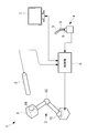
本実施形態に係る医療用マニピュレータシステム1は、図1に示されるように、内視鏡2と、該内視鏡2を先端に保持して移動させるマニピュレータ3と、操作者により操作指令を入力させる操作部4と、該操作部4に入力された操作指令に基づいてマニピュレータ3を制御する制御部5と、マニピュレータ3の先端に固定され、内視鏡2を取り付けるためのホルダ(被挿入部材)6と、内視鏡2によって取得された画像を表示するモニタ7とを備えている。
本実施形態に係る医療用マニピュレータシステム1は、図1に示されるように、内視鏡2と、該内視鏡2を先端に保持して移動させるマニピュレータ3と、操作者により操作指令を入力させる操作部4と、該操作部4に入力された操作指令に基づいてマニピュレータ3を制御する制御部5と、マニピュレータ3の先端に固定され、内視鏡2を取り付けるためのホルダ(被挿入部材)6と、内視鏡2によって取得された画像を表示するモニタ7とを備えている。
内視鏡2は先端に撮像部(図示略)を有し、先端に対向して配置された被写体の画像を取得することができるようになっている。内視鏡2は、細長い形態を有している。内視鏡2の種別には、長手軸方向の前方の正面の画像を取得する直視型と、斜め前方の画像を取得する斜視型とがあり、斜視型には傾斜角度の異なるものが存在する。
マニピュレータ3は、例えば、多関節構造を有し、先端に固定されたホルダ6の位置および姿勢を設定することができる自由度を有している。
操作部4も、例えば、マニピュレータ3と相似形あるいは疑似相似形の多関節構造を有し、操作者が把持して操作するハンドル8の位置および姿勢を達成するための各関節9の角度を動作指令として検出して制御部5に出力するようになっている。
操作部4も、例えば、マニピュレータ3と相似形あるいは疑似相似形の多関節構造を有し、操作者が把持して操作するハンドル8の位置および姿勢を達成するための各関節9の角度を動作指令として検出して制御部5に出力するようになっている。
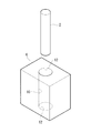
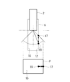
ホルダ6は、図2に示されるように、内視鏡2をマニピュレータ3に装着する際に、内視鏡2を挿入する貫通孔10を備えるとともに、該貫通孔10に挿入された内視鏡2を固定するための図示しない固定機構を備えている。また、ホルダ6の貫通孔10の内面には、後述するスコープ種別認識部11により内視鏡2の種別を認識するためのマーカが設けられている。マーカとしては任意の形状でよいが、ホルダ6に設けられた貫通孔10の開口部12自体をマーカとして用いてもよい。
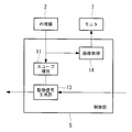
制御部5は、図3に示されるように、操作部4から送られてきた動作指令を受け取って、マニピュレータ3の各関節15を駆動する駆動指令信号を生成し、マニピュレータ3に対して出力する駆動信号生成部(制御部)13と、内視鏡2をホルダ6の貫通孔10に挿入する際に撮像部により取得される画像によって内視鏡2の種別を認識するスコープ種別認識部11と、撮像部により取得された画像を処理してモニタ7に表示させる画像処理部14とを備えている。
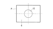
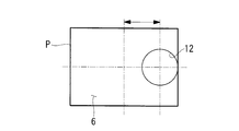
スコープ種別認識部11は、内視鏡2をホルダ6の貫通孔10に挿入する際に撮像部によって取得された画像Pが、図4Aに示されるように、画像Pの中央に貫通孔10の開口部12を有する場合には、内視鏡2の種別が直視型であると認識するようになっている。また、内視鏡2をホルダ6の貫通孔10に挿入する際に撮像部によって取得された画像Pが、図4A及び図4Cに示されるように、画像Pの中央に対して一方向にずれた位置に貫通孔10の開口部12を有する場合には、内視鏡2の種別が斜視型であると認識するようになっている。
また、スコープ種別認識部11は、内視鏡2をホルダ6の貫通孔10に所定深さだけ挿入したときの画像Pの中央に対する貫通孔10の開口部12のズレ量が、図4B及び図4Cに示されるように異なるときに、ズレ量が大きいほど撮像部の光軸の内視鏡2の長手軸に対する傾斜角度が大きくなると認識するようになっている。例えば、図4Bの場合には、傾斜角度は30°、図4Cの場合には、傾斜角度は45°である。
駆動信号生成部13は、スコープ種別認識部11により認識された内視鏡2の種別の情報を受け取って、マニピュレータ3の動作を切り替えるようになっている。
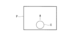
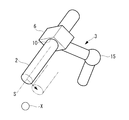
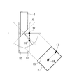
例えば、図5Aに示されるように、斜視型の内視鏡2がホルダ6に固定され、図5Bに示されるような被写体Xの画像Pが取得されモニタ7に表示されている場合に、画像P上で被写体Xを矢印に示す方向に移動させるには、図5Aにおいて内視鏡2の先端を光軸Sに直交する矢印の方向に移動させる必要がある。
例えば、図5Aに示されるように、斜視型の内視鏡2がホルダ6に固定され、図5Bに示されるような被写体Xの画像Pが取得されモニタ7に表示されている場合に、画像P上で被写体Xを矢印に示す方向に移動させるには、図5Aにおいて内視鏡2の先端を光軸Sに直交する矢印の方向に移動させる必要がある。
一方、図5Cに示されるように、直視型の内視鏡2がホルダ6に固定され、図5Bに示されるような被写体Xの画像Pが取得されモニタ7に表示されている場合にも、画像P上で被写体Xを矢印に示す方向に移動させるには、図5Cにおいて内視鏡2の先端を光軸Sに直交する矢印の方向に移動させる必要がある。この場合の動作方向は図5Aの場合とは異なっており、この動作を達成するためのマニピュレータ3の動作も異なっている。
駆動信号生成部13は、内視鏡2の種別に応じてマニピュレータ3の動作を切り替えることにより、操作者が操作部4を介して行う同じ操作によって、内視鏡2により取得される画像P内の被写体Xの動きが同じになるように、マニピュレータ3を制御するようになっている。
このように構成された本実施形態に係る医療用マニピュレータシステム1の作用について以下に説明する。
本実施形態に係る医療用マニピュレータシステム1を用いて患者の体内の観察を行うには、まず、内視鏡2の電源を投入し、先端の撮像部によって画像Pを取得できる状態として、マニピュレータ3の先端に備えられたホルダ6の貫通孔10に内視鏡2を先端側から所定量だけ挿入する。
本実施形態に係る医療用マニピュレータシステム1を用いて患者の体内の観察を行うには、まず、内視鏡2の電源を投入し、先端の撮像部によって画像Pを取得できる状態として、マニピュレータ3の先端に備えられたホルダ6の貫通孔10に内視鏡2を先端側から所定量だけ挿入する。
すると、撮像部により貫通孔10内面を含む画像Pが取得され、画像P内にホルダ6の貫通孔10の開口部12が写る。この画像Pがスコープ種別認識部11に送られることにより、画像処理によって画像P内の開口部12の位置が算出される。画像処理の結果、開口部12の中心位置が、画像中心から所定の範囲内に配置されている場合には、内視鏡2の種別が直視型であると認識される。また、画像処理の結果、開口部12の中心位置が、画像中心からずれている場合には、内視鏡2の種別が斜視型であると認識され、ズレ量に応じて、傾斜角度が認識される。そして、スコープ種別認識部11における認識結果は、駆動信号生成部13に送られる。
駆動信号生成部13においては、送られてきた内視鏡2の種別の情報に基づいて、マニピュレータ3の制御が切り替えられる。
そして、ホルダ6の貫通孔10に挿入した内視鏡2をホルダ6に固定し、操作者が、操作部4を操作することにより、マニピュレータ3が駆動され、内視鏡2によって取得されモニタ7に表示されている画像P内における被写体Xの位置を変更することができる。
そして、ホルダ6の貫通孔10に挿入した内視鏡2をホルダ6に固定し、操作者が、操作部4を操作することにより、マニピュレータ3が駆動され、内視鏡2によって取得されモニタ7に表示されている画像P内における被写体Xの位置を変更することができる。
この場合において、本実施形態に係る医療用マニピュレータシステム1によれば、内視鏡2の種別の情報に基づいて、マニピュレータ3の制御が切り替えられるので、操作者は、装着されている内視鏡2の種別を意識することなく、操作部4に対する同じ操作によって、モニタ7に表示されている画像Pの位置を同じ方向に移動させることができる。
このように、本実施形態に係る医療用マニピュレータシステム1によれば、内視鏡2の種別に応じて操作者が操作部4に対する操作を変更する必要がないので、操作性を向上することができるという利点がある。また、内視鏡2に識別情報を持たせるのではなく、内視鏡2によって取得された画像Pにより種別を認識するので、既存の内視鏡2を用いても同様に操作性を向上することができる。
なお、本実施形態においては、内視鏡2の種別に応じて制御を切り替えることとしたが、これに代えて、認識した内視鏡2の種別を操作者に対して表示して、種別に合わせて、操作者が行う操作を変更させることにしてもよい。
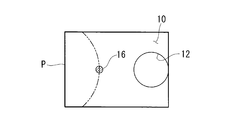
また、本実施形態に係る医療用マニピュレータシステム1においては、ホルダ6の貫通孔10の開口部12をマーカとして利用することとしたが、これに代えて、貫通孔10の内面にドット状の他のマーカ16を付することにしてもよい。
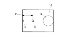
また、図6Aから図6Cに示されるように、貫通孔10の長手方向に間隔をあけて2つのドット状のマーカ17,18を付しておき、手前側のマーカ17が画像の最端部に配置されたときのマーカ17,18間の距離によって、直視型、30°斜視型、45°斜視型のように内視鏡2の種別を認識することにしてもよい。
すなわち、図7Aから図7Cに示されるように、直視型の内視鏡2の場合のマーカ17,18間の距離が最も小さく、次いで、30°斜視型、45°斜視型の純にマーカ17,18間の距離が大きくなるので、これを検出することにより、簡易に内視鏡2の種別を認識することができる。
すなわち、図7Aから図7Cに示されるように、直視型の内視鏡2の場合のマーカ17,18間の距離が最も小さく、次いで、30°斜視型、45°斜視型の純にマーカ17,18間の距離が大きくなるので、これを検出することにより、簡易に内視鏡2の種別を認識することができる。
また、図8および図9Aから図9Cに示されるように、ホルダ6の貫通孔10に内視鏡2を挿入した状態で、内視鏡2の長手軸回りに内視鏡2を回転させることにより、貫通孔10内面のドット状のマーカ16が円弧状の移動軌跡を描いて移動する。したがって、その移動軌跡の半径を検出することによっても、内視鏡2の種別を簡易に認識することができる。
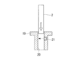
また、本実施形態においては、内視鏡2を挿入させる被挿入部材として、内視鏡2をマニピュレータ3に取り付ける際に挿入させる貫通孔10を備えるホルダ6を例示したが、これに代えて、図10に示されるように、患者の体表組織に、該体表組織を貫通して取付状態に配置されるトロッカ19を採用してもよい。
図10に示す例では、トロッカ19が、内視鏡2を挿入させる貫通孔20を備えるとともに、貫通孔20の内面に、該内面から挿入された内視鏡2の外面までの距離を測定する距離センサ(外面位置検出部)21を備えている。
距離センサ21としては、光を射出して内視鏡2の外面で反射した反射光を受光する光学式のものを例示することができる。
距離センサ21としては、光を射出して内視鏡2の外面で反射した反射光を受光する光学式のものを例示することができる。
このようにすることで、トロッカ19の貫通孔20に内視鏡2の先端を挿入していくと、貫通孔20の内面から内視鏡2の外面までの距離が逐次検出されていくので、図11A及び図11Bに示されるように、距離が順次変化する場合には斜視型、図12A及び図12Bに示されるように、距離が急激に変化する場合には直視型であると認識することができる。
また、図13Aに示されるように、トロッカ19に、内視鏡2の挿入量を検出するエンコーダ22を設けておき、エンコーダ(挿入量検出部)22により検出される挿入量と、距離センサ21により検出される距離との関係から斜視型の傾斜角度を判別することにしてもよい。すなわち、図13Bに示されるように、挿入量に対する距離のグラフの傾きによって、直接的に斜視型の内視鏡2の傾斜角度を認識することができる。
1 医療用マニピュレータシステム
2 内視鏡
3 マニピュレータ
4 操作部
5 制御部
6 ホルダ(被挿入部材、保持部)
10,20 貫通孔
11 スコープ種別認識部
12 開口部(マーカ)
16,17,18 マーカ
19 トロッカ(被挿入部材)
21 距離センサ(外面位置検出部)
22 エンコーダ(挿入量検出部)
2 内視鏡
3 マニピュレータ
4 操作部
5 制御部
6 ホルダ(被挿入部材、保持部)
10,20 貫通孔
11 スコープ種別認識部
12 開口部(マーカ)
16,17,18 マーカ
19 トロッカ(被挿入部材)
21 距離センサ(外面位置検出部)
22 エンコーダ(挿入量検出部)
Claims (9)
- 撮像部を備える内視鏡と、
該内視鏡を先端に保持して移動させるマニピュレータと、
操作者により操作指令を入力させる操作部と、
該操作部に入力された操作指令に基づいて前記マニピュレータを制御する制御部と、
前記内視鏡の使用に際して前記内視鏡を挿入させる貫通孔を有する被挿入部材と、
前記貫通孔に前記内視鏡が挿入された状態で該内視鏡により取得された前記貫通孔の内面を含む画像に基づいて前記内視鏡の種別を認識するスコープ種別認識部とを備える医療用マニピュレータシステム。 - 撮像部を備える内視鏡を先端に保持して移動させるマニピュレータと、
操作者により操作指令を入力させる操作部と、
該操作部に入力された操作指令に基づいて前記マニピュレータを制御する制御部と、
前記内視鏡の使用に際して前記内視鏡を挿入させる貫通孔を有するとともに、該貫通孔に挿入される前記内視鏡の外面の径方向位置を逐次検出する外面位置検出部を有する被挿入部材と、
前記貫通孔への前記内視鏡の挿入時に前記外面位置検出部により検出された外面の径方向位置の時間変化に基づいて前記内視鏡の種別を認識するスコープ種別認識部とを備える医療用マニピュレータシステム。 - 前記画像が、前記貫通孔の内面のマーカの画像を含み、
前記スコープ種別認識部が、前記画像内の前記マーカの位置に基づいて前記内視鏡の種別を認識する請求項1に記載の医療用マニピュレータシステム。 - 前記マーカが、前記貫通孔の開口部である請求項3に記載の医療用マニピュレータシステム。
- 前記スコープ種別認識部が、前記貫通孔に前記内視鏡を挿入した状態で、前記貫通孔に対して前記内視鏡をその長手軸回りに回転させることにより得られる前記マーカの移動軌跡に基づいて前記内視鏡の種別を認識する請求項3または請求項4に記載の医療用マニピュレータシステム。
- 前記被挿入部材が前記貫通孔への前記内視鏡の挿入量を検出する挿入量検出部をさらに備え、
前記スコープ種別認識部が、前記挿入量検出部により検出された挿入量と該挿入量に対応して検出された前記径方向位置とに基づいて前記内視鏡の種別を認識する請求項2に記載の医療用マニピュレータシステム。 - 前記被挿入部材が、前記マニピュレータの先端に取り付けられ、前記内視鏡を保持する保持部である請求項1から請求項6のいずれか一項に記載の医療用マニピュレータシステム。
- 前記被挿入部材が、患者の体表組織を貫通して該体表組織に装着されるトロッカである請求項1から請求項6のいずれか一項に記載の医療用マニピュレータシステム。
- 前記スコープ種別認識部により認識された内視鏡の種別に基づいて、前記制御部が、前記操作部に入力された同じ操作指令に対して、前記撮像部の光軸が同じ方向に動作させられるように前記マニピュレータの制御を切り替える請求項1から請求項8のいずれか一項に記載の医療用マニピュレータシステム。
Priority Applications (4)
| Application Number | Priority Date | Filing Date | Title |
|---|---|---|---|
| CN201680005031.3A CN107105983B (zh) | 2015-05-27 | 2016-05-26 | 医疗用机械手系统 |
| EP16800097.4A EP3305166A4 (en) | 2015-05-27 | 2016-05-26 | MEDICAL MANIPULATOR SYSTEM |
| JP2017514593A JP6138407B2 (ja) | 2015-05-27 | 2016-05-26 | 医療用マニピュレータシステム |
| US15/815,974 US20180071034A1 (en) | 2015-05-27 | 2017-11-17 | Medical manipulator system |
Applications Claiming Priority (2)
| Application Number | Priority Date | Filing Date | Title |
|---|---|---|---|
| JP2015107480 | 2015-05-27 | ||
| JP2015-107480 | 2015-05-27 |
Related Child Applications (1)
| Application Number | Title | Priority Date | Filing Date |
|---|---|---|---|
| US15/815,974 Continuation US20180071034A1 (en) | 2015-05-27 | 2017-11-17 | Medical manipulator system |
Publications (1)
| Publication Number | Publication Date |
|---|---|
| WO2016190393A1 true WO2016190393A1 (ja) | 2016-12-01 |
Family
ID=57392929
Family Applications (1)
| Application Number | Title | Priority Date | Filing Date |
|---|---|---|---|
| PCT/JP2016/065607 Ceased WO2016190393A1 (ja) | 2015-05-27 | 2016-05-26 | 医療用マニピュレータシステム |
Country Status (5)
| Country | Link |
|---|---|
| US (1) | US20180071034A1 (ja) |
| EP (1) | EP3305166A4 (ja) |
| JP (1) | JP6138407B2 (ja) |
| CN (1) | CN107105983B (ja) |
| WO (1) | WO2016190393A1 (ja) |
Cited By (1)
| Publication number | Priority date | Publication date | Assignee | Title |
|---|---|---|---|---|
| WO2018235389A1 (ja) * | 2017-06-20 | 2018-12-27 | オリンパス株式会社 | 医療表示装置 |
Families Citing this family (3)
| Publication number | Priority date | Publication date | Assignee | Title |
|---|---|---|---|---|
| CN111528762A (zh) * | 2020-04-13 | 2020-08-14 | 珠海明象医用科技有限公司 | 一种无线内窥镜工作站 |
| US20220117673A1 (en) * | 2020-10-19 | 2022-04-21 | Arthur C. McKinley | EndoInspect Apparatus, System and Method |
| CN112402038B (zh) * | 2020-11-20 | 2022-09-13 | 山东威高医疗科技有限公司 | 与电磁导航系统配套使用的器械的自动识别方法 |
Citations (6)
| Publication number | Priority date | Publication date | Assignee | Title |
|---|---|---|---|---|
| JPH07328014A (ja) * | 1994-06-10 | 1995-12-19 | Olympus Optical Co Ltd | 手術装置 |
| JP2003019683A (ja) * | 1993-12-28 | 2003-01-21 | Olympus Optical Co Ltd | 手術ロボット |
| JP2009226029A (ja) * | 2008-03-24 | 2009-10-08 | Terumo Corp | マニピュレータ |
| JP2012019982A (ja) * | 2010-07-15 | 2012-02-02 | Fujifilm Corp | 内視鏡システム |
| WO2014078538A1 (en) * | 2012-11-15 | 2014-05-22 | Intuitive Surgical Operations, Inc. | Endoscopic systems with low capacitance and/or electromagnetic shielding, and related methods |
| US20140163359A1 (en) * | 2011-08-21 | 2014-06-12 | Mordehai Sholev | Device and method for assisting laparoscopic surgery - rule based approach |
Family Cites Families (6)
| Publication number | Priority date | Publication date | Assignee | Title |
|---|---|---|---|---|
| US5876325A (en) * | 1993-11-02 | 1999-03-02 | Olympus Optical Co., Ltd. | Surgical manipulation system |
| JP4754738B2 (ja) * | 2001-08-30 | 2011-08-24 | オリンパス株式会社 | 医療用保持装置及び医療装置 |
| JP3938722B2 (ja) * | 2002-07-03 | 2007-06-27 | オリンパス株式会社 | 内視鏡装置 |
| US8373748B2 (en) * | 2005-12-14 | 2013-02-12 | Stryker Corporation | Automatic endoscope recognition and selection of image processing and display settings |
| US9788906B2 (en) * | 2013-03-15 | 2017-10-17 | Synaptive Medical (Barbados) Inc. | Context aware surgical systems for intraoperatively configuring imaging devices |
| JP6161687B2 (ja) * | 2013-03-28 | 2017-07-12 | オリンパス株式会社 | 内視鏡システムおよび内視鏡システムの作動方法 |
-
2016
- 2016-05-26 WO PCT/JP2016/065607 patent/WO2016190393A1/ja not_active Ceased
- 2016-05-26 JP JP2017514593A patent/JP6138407B2/ja active Active
- 2016-05-26 EP EP16800097.4A patent/EP3305166A4/en not_active Withdrawn
- 2016-05-26 CN CN201680005031.3A patent/CN107105983B/zh active Active
-
2017
- 2017-11-17 US US15/815,974 patent/US20180071034A1/en not_active Abandoned
Patent Citations (6)
| Publication number | Priority date | Publication date | Assignee | Title |
|---|---|---|---|---|
| JP2003019683A (ja) * | 1993-12-28 | 2003-01-21 | Olympus Optical Co Ltd | 手術ロボット |
| JPH07328014A (ja) * | 1994-06-10 | 1995-12-19 | Olympus Optical Co Ltd | 手術装置 |
| JP2009226029A (ja) * | 2008-03-24 | 2009-10-08 | Terumo Corp | マニピュレータ |
| JP2012019982A (ja) * | 2010-07-15 | 2012-02-02 | Fujifilm Corp | 内視鏡システム |
| US20140163359A1 (en) * | 2011-08-21 | 2014-06-12 | Mordehai Sholev | Device and method for assisting laparoscopic surgery - rule based approach |
| WO2014078538A1 (en) * | 2012-11-15 | 2014-05-22 | Intuitive Surgical Operations, Inc. | Endoscopic systems with low capacitance and/or electromagnetic shielding, and related methods |
Non-Patent Citations (1)
| Title |
|---|
| See also references of EP3305166A4 * |
Cited By (5)
| Publication number | Priority date | Publication date | Assignee | Title |
|---|---|---|---|---|
| WO2018235389A1 (ja) * | 2017-06-20 | 2018-12-27 | オリンパス株式会社 | 医療表示装置 |
| JP6495565B1 (ja) * | 2017-06-20 | 2019-04-03 | オリンパス株式会社 | 医療表示装置 |
| CN110785111A (zh) * | 2017-06-20 | 2020-02-11 | 奥林巴斯株式会社 | 医疗显示装置 |
| US10972705B2 (en) | 2017-06-20 | 2021-04-06 | Olympus Corporation | Medical display apparatus, endoscopic surgery system, and method of displaying medical image |
| CN110785111B (zh) * | 2017-06-20 | 2021-12-21 | 奥林巴斯株式会社 | 医疗显示装置 |
Also Published As
| Publication number | Publication date |
|---|---|
| CN107105983A (zh) | 2017-08-29 |
| JPWO2016190393A1 (ja) | 2017-06-15 |
| EP3305166A4 (en) | 2019-01-23 |
| EP3305166A1 (en) | 2018-04-11 |
| JP6138407B2 (ja) | 2017-05-31 |
| US20180071034A1 (en) | 2018-03-15 |
| CN107105983B (zh) | 2019-03-26 |
Similar Documents
| Publication | Publication Date | Title |
|---|---|---|
| JP6284284B2 (ja) | ジェスチャ制御を用いるロボットシステム制御用の制御装置及び方法 | |
| KR102105142B1 (ko) | 입력 장치의 오퍼레이터가 볼 수 있는 디스플레이 영역으로 기구가 진입할 때 기구의 제어를 입력 장치로 전환하는 방법 | |
| JP4744595B2 (ja) | 内視鏡外科手術器具 | |
| CN108348134B (zh) | 内窥镜系统 | |
| JP6138407B2 (ja) | 医療用マニピュレータシステム | |
| JP6177488B2 (ja) | マニピュレータ及び医療システム | |
| CN105407817B (zh) | 医疗系统和医疗用器具控制方法 | |
| CN104023614B (zh) | 立体内窥镜装置、立体内窥镜系统和立体内窥镜机器人 | |
| JP5904750B2 (ja) | 立体内視鏡装置 | |
| CN107847285B (zh) | 输入机构和医疗系统 | |
| US11540699B2 (en) | Medical manipulator system | |
| JP2019506922A (ja) | ロボット手術のために仮想現実デバイスを使用するシステム、コントローラ、及び方法 | |
| WO2017014303A1 (ja) | 医療システム及びその作動方法 | |
| KR20110008189A (ko) | 제어자의 모션을 로봇 매니퓰레이터로부터 부착된 기구로 전달하기 위한 커플러 | |
| CN110934641B (zh) | 手术辅助装置及其控制方法、以及手术辅助系统 | |
| US10694928B2 (en) | Endoscope system | |
| JP6104479B2 (ja) | マニピュレータシステム | |
| JP6286575B2 (ja) | 内視鏡用外科手術装置 | |
| CN106455920B (zh) | 内窥镜系统 | |
| JP2016506762A (ja) | 医療機器 | |
| US10568490B2 (en) | Surgical apparatus for endoscope | |
| JP6893036B2 (ja) | 手術支援装置、その制御方法及びプログラム、並びに手術支援システム | |
| US20180344418A1 (en) | Medical manipulator system and method for controlling a medical manipulator | |
| JP2025151383A (ja) | 内視鏡システム、制御装置、制御方法およびプログラム |
Legal Events
| Date | Code | Title | Description |
|---|---|---|---|
| 121 | Ep: the epo has been informed by wipo that ep was designated in this application |
Ref document number: 16800097 Country of ref document: EP Kind code of ref document: A1 |
|
| ENP | Entry into the national phase |
Ref document number: 2017514593 Country of ref document: JP Kind code of ref document: A |
|
| NENP | Non-entry into the national phase |
Ref country code: DE |