WO2016194036A1 - レーダ信号処理装置 - Google Patents
レーダ信号処理装置 Download PDFInfo
- Publication number
- WO2016194036A1 WO2016194036A1 PCT/JP2015/065529 JP2015065529W WO2016194036A1 WO 2016194036 A1 WO2016194036 A1 WO 2016194036A1 JP 2015065529 W JP2015065529 W JP 2015065529W WO 2016194036 A1 WO2016194036 A1 WO 2016194036A1
- Authority
- WO
- WIPO (PCT)
- Prior art keywords
- signal processing
- radar signal
- radar
- degree
- category
- Prior art date
- Legal status (The legal status is an assumption and is not a legal conclusion. Google has not performed a legal analysis and makes no representation as to the accuracy of the status listed.)
- Ceased
Links
Images



Classifications
-
- G—PHYSICS
- G01—MEASURING; TESTING
- G01S—RADIO DIRECTION-FINDING; RADIO NAVIGATION; DETERMINING DISTANCE OR VELOCITY BY USE OF RADIO WAVES; LOCATING OR PRESENCE-DETECTING BY USE OF THE REFLECTION OR RERADIATION OF RADIO WAVES; ANALOGOUS ARRANGEMENTS USING OTHER WAVES
- G01S13/00—Systems using the reflection or reradiation of radio waves, e.g. radar systems; Analogous systems using reflection or reradiation of waves whose nature or wavelength is irrelevant or unspecified
- G01S13/88—Radar or analogous systems specially adapted for specific applications
- G01S13/93—Radar or analogous systems specially adapted for specific applications for anti-collision purposes
- G01S13/931—Radar or analogous systems specially adapted for specific applications for anti-collision purposes of land vehicles
-
- G—PHYSICS
- G01—MEASURING; TESTING
- G01S—RADIO DIRECTION-FINDING; RADIO NAVIGATION; DETERMINING DISTANCE OR VELOCITY BY USE OF RADIO WAVES; LOCATING OR PRESENCE-DETECTING BY USE OF THE REFLECTION OR RERADIATION OF RADIO WAVES; ANALOGOUS ARRANGEMENTS USING OTHER WAVES
- G01S13/00—Systems using the reflection or reradiation of radio waves, e.g. radar systems; Analogous systems using reflection or reradiation of waves whose nature or wavelength is irrelevant or unspecified
- G01S13/02—Systems using reflection of radio waves, e.g. primary radar systems; Analogous systems
- G01S13/06—Systems determining position data of a target
- G01S13/42—Simultaneous measurement of distance and other co-ordinates
-
- G—PHYSICS
- G01—MEASURING; TESTING
- G01S—RADIO DIRECTION-FINDING; RADIO NAVIGATION; DETERMINING DISTANCE OR VELOCITY BY USE OF RADIO WAVES; LOCATING OR PRESENCE-DETECTING BY USE OF THE REFLECTION OR RERADIATION OF RADIO WAVES; ANALOGOUS ARRANGEMENTS USING OTHER WAVES
- G01S13/00—Systems using the reflection or reradiation of radio waves, e.g. radar systems; Analogous systems using reflection or reradiation of waves whose nature or wavelength is irrelevant or unspecified
- G01S13/02—Systems using reflection of radio waves, e.g. primary radar systems; Analogous systems
- G01S13/06—Systems determining position data of a target
- G01S13/46—Indirect determination of position data
-
- G—PHYSICS
- G01—MEASURING; TESTING
- G01S—RADIO DIRECTION-FINDING; RADIO NAVIGATION; DETERMINING DISTANCE OR VELOCITY BY USE OF RADIO WAVES; LOCATING OR PRESENCE-DETECTING BY USE OF THE REFLECTION OR RERADIATION OF RADIO WAVES; ANALOGOUS ARRANGEMENTS USING OTHER WAVES
- G01S13/00—Systems using the reflection or reradiation of radio waves, e.g. radar systems; Analogous systems using reflection or reradiation of waves whose nature or wavelength is irrelevant or unspecified
- G01S13/02—Systems using reflection of radio waves, e.g. primary radar systems; Analogous systems
- G01S13/50—Systems of measurement based on relative movement of target
- G01S13/58—Velocity or trajectory determination systems; Sense-of-movement determination systems
- G01S13/581—Velocity or trajectory determination systems; Sense-of-movement determination systems using transmission of interrupted pulse modulated waves and based upon the Doppler effect resulting from movement of targets
- G01S13/582—Velocity or trajectory determination systems; Sense-of-movement determination systems using transmission of interrupted pulse modulated waves and based upon the Doppler effect resulting from movement of targets adapted for simultaneous range and velocity measurements
-
- G—PHYSICS
- G01—MEASURING; TESTING
- G01S—RADIO DIRECTION-FINDING; RADIO NAVIGATION; DETERMINING DISTANCE OR VELOCITY BY USE OF RADIO WAVES; LOCATING OR PRESENCE-DETECTING BY USE OF THE REFLECTION OR RERADIATION OF RADIO WAVES; ANALOGOUS ARRANGEMENTS USING OTHER WAVES
- G01S13/00—Systems using the reflection or reradiation of radio waves, e.g. radar systems; Analogous systems using reflection or reradiation of waves whose nature or wavelength is irrelevant or unspecified
- G01S13/02—Systems using reflection of radio waves, e.g. primary radar systems; Analogous systems
- G01S13/50—Systems of measurement based on relative movement of target
- G01S13/58—Velocity or trajectory determination systems; Sense-of-movement determination systems
- G01S13/583—Velocity or trajectory determination systems; Sense-of-movement determination systems using transmission of continuous unmodulated waves, amplitude-, frequency-, or phase-modulated waves and based upon the Doppler effect resulting from movement of targets
- G01S13/584—Velocity or trajectory determination systems; Sense-of-movement determination systems using transmission of continuous unmodulated waves, amplitude-, frequency-, or phase-modulated waves and based upon the Doppler effect resulting from movement of targets adapted for simultaneous range and velocity measurements
-
- G—PHYSICS
- G01—MEASURING; TESTING
- G01S—RADIO DIRECTION-FINDING; RADIO NAVIGATION; DETERMINING DISTANCE OR VELOCITY BY USE OF RADIO WAVES; LOCATING OR PRESENCE-DETECTING BY USE OF THE REFLECTION OR RERADIATION OF RADIO WAVES; ANALOGOUS ARRANGEMENTS USING OTHER WAVES
- G01S7/00—Details of systems according to groups G01S13/00, G01S15/00, G01S17/00
- G01S7/02—Details of systems according to groups G01S13/00, G01S15/00, G01S17/00 of systems according to group G01S13/00
- G01S7/41—Details of systems according to groups G01S13/00, G01S15/00, G01S17/00 of systems according to group G01S13/00 using analysis of echo signal for target characterisation; Target signature; Target cross-section
-
- G—PHYSICS
- G01—MEASURING; TESTING
- G01S—RADIO DIRECTION-FINDING; RADIO NAVIGATION; DETERMINING DISTANCE OR VELOCITY BY USE OF RADIO WAVES; LOCATING OR PRESENCE-DETECTING BY USE OF THE REFLECTION OR RERADIATION OF RADIO WAVES; ANALOGOUS ARRANGEMENTS USING OTHER WAVES
- G01S7/00—Details of systems according to groups G01S13/00, G01S15/00, G01S17/00
- G01S7/02—Details of systems according to groups G01S13/00, G01S15/00, G01S17/00 of systems according to group G01S13/00
- G01S7/41—Details of systems according to groups G01S13/00, G01S15/00, G01S17/00 of systems according to group G01S13/00 using analysis of echo signal for target characterisation; Target signature; Target cross-section
- G01S7/411—Identification of targets based on measurements of radar reflectivity
-
- G—PHYSICS
- G01—MEASURING; TESTING
- G01S—RADIO DIRECTION-FINDING; RADIO NAVIGATION; DETERMINING DISTANCE OR VELOCITY BY USE OF RADIO WAVES; LOCATING OR PRESENCE-DETECTING BY USE OF THE REFLECTION OR RERADIATION OF RADIO WAVES; ANALOGOUS ARRANGEMENTS USING OTHER WAVES
- G01S7/00—Details of systems according to groups G01S13/00, G01S15/00, G01S17/00
- G01S7/02—Details of systems according to groups G01S13/00, G01S15/00, G01S17/00 of systems according to group G01S13/00
- G01S7/41—Details of systems according to groups G01S13/00, G01S15/00, G01S17/00 of systems according to group G01S13/00 using analysis of echo signal for target characterisation; Target signature; Target cross-section
- G01S7/415—Identification of targets based on measurements of movement associated with the target
-
- G—PHYSICS
- G01—MEASURING; TESTING
- G01S—RADIO DIRECTION-FINDING; RADIO NAVIGATION; DETERMINING DISTANCE OR VELOCITY BY USE OF RADIO WAVES; LOCATING OR PRESENCE-DETECTING BY USE OF THE REFLECTION OR RERADIATION OF RADIO WAVES; ANALOGOUS ARRANGEMENTS USING OTHER WAVES
- G01S13/00—Systems using the reflection or reradiation of radio waves, e.g. radar systems; Analogous systems using reflection or reradiation of waves whose nature or wavelength is irrelevant or unspecified
- G01S13/02—Systems using reflection of radio waves, e.g. primary radar systems; Analogous systems
- G01S13/06—Systems determining position data of a target
- G01S13/46—Indirect determination of position data
- G01S2013/462—Indirect determination of position data using multipath signals
-
- G—PHYSICS
- G01—MEASURING; TESTING
- G01S—RADIO DIRECTION-FINDING; RADIO NAVIGATION; DETERMINING DISTANCE OR VELOCITY BY USE OF RADIO WAVES; LOCATING OR PRESENCE-DETECTING BY USE OF THE REFLECTION OR RERADIATION OF RADIO WAVES; ANALOGOUS ARRANGEMENTS USING OTHER WAVES
- G01S13/00—Systems using the reflection or reradiation of radio waves, e.g. radar systems; Analogous systems using reflection or reradiation of waves whose nature or wavelength is irrelevant or unspecified
- G01S13/88—Radar or analogous systems specially adapted for specific applications
- G01S13/93—Radar or analogous systems specially adapted for specific applications for anti-collision purposes
- G01S13/931—Radar or analogous systems specially adapted for specific applications for anti-collision purposes of land vehicles
- G01S2013/93185—Controlling the brakes
Definitions
- the present invention relates to a radar signal processing device of an on-vehicle radar device, and more particularly to a technique for assisting in determining whether or not to perform braking control by identifying a reflecting object into a predetermined category.
- measurement results such as the relative distance, relative speed, bearing, and reflection intensity between the vehicle and the reflective object, measured by the on-vehicle radar device, reduce damage when the vehicle collides with an obstacle ahead.
- This system is used in in-vehicle applications to improve vehicle safety and comfort, such as the collision damage reduction brake system and the adaptive cruise control system that follows the vehicle ahead.
- the height from the road surface of the target is estimated from the power distribution of the target (null point generation pattern by multipath), and it is determined whether or not the target is a braking target.
- the height of an object is estimated by collating the amplitude pattern dictionary (database) created beforehand using the various objects with known height.
- the subject is based on the reception intensity (radar reflection cross-sectional area) and the variation (standard deviation) in the reception intensity difference between the upstream and downstream frequencies in the FMCW (Frequency Modulated Continuous Wave) method. Whether it is a vehicle or a human is identified, and it is determined whether or not it is a braking target.
- reception intensity radar reflection cross-sectional area
- variation standard deviation
- Patent Literature 1 and Patent Literature 2 Since the conventional apparatus is configured as described above, in Patent Literature 1 and Patent Literature 2, since the determination is performed based only on the feature amount derived from the signal intensity, the measurement result cannot be obtained normally. There is a problem that the estimation accuracy deteriorates. Further, in the method of collating a dictionary as in Patent Document 2, it is necessary to acquire a huge number of data in order to create a dictionary for performing highly accurate estimation. There is a problem that a large-capacity memory is required and the cost is high. Further, in the method of Patent Document 3, the object to be identified in advance can narrow down the braking target / non-braking target.
- the radar reflection cross-sectional area is the beam pattern, Since it depends on the material, posture, and distance of the object, it is considered difficult to make a stable determination. In addition, a certain amount of data needs to be accumulated to calculate the variation. There is a possibility that the response to the situation where there is no margin can be delayed.
- the present invention has been made in order to solve the above-described problems, and is a radar capable of identifying an object using features of the object extracted from a radar measurement value and determining a braking target and a non-braking target with high accuracy.
- An object is to obtain a signal processing device.
- the radar signal processing apparatus extracts, as primary feature amounts, information related to at least the relative distance and relative velocity between a plurality of objects and the azimuth and reflection intensity of the objects from a radar reception signal at a constant time period.
- a quantity extraction unit a data storage processing unit that stores primary feature values and associates a plurality of primary feature values with the same object in time series over a plurality of cycles, and a secondary feature from the primary feature values in the data storage processing unit
- a secondary feature amount extraction unit that extracts a quantity; an attribution level calculation unit that calculates a degree of attribution of the distribution of the secondary feature quantity with respect to a predetermined category; and an object determination unit that determines a category of an object based on the degree of attribution It is equipped with.
- the category (type) of the object is determined using the amount of change in the reflection intensity of the object acquired by the radar for a short time as a feature quantity, so that accuracy can be obtained from a short time or from a small number of measurement points. Can be identified.
- the radar signal processing apparatus according to the present invention determines the category (type) of the object based on a plurality of feature values of the object acquired by the radar. can do.
- FIG. 1 is a block diagram showing a radar signal processing device of an in-vehicle radar device (also referred to as “radar”) according to Embodiment 1 of the present invention.
- a radar signal processing apparatus 10 shown in FIG. 1 includes a primary feature quantity extraction unit 11, a data storage processing unit 12, a secondary feature quantity extraction unit 13, an attribution level calculation unit 14, an attribution level database 15, and an object determination unit 16. Yes.
- the part that radiates radio waves to an object (not shown) and receives the reflected wave from the object (also referred to as “reflecting object”) and its method (FMCW method, FMICW method, pulse Doppler method, etc.) and overall control Since the portion for performing the above is the same as that of a general on-vehicle radar, description thereof is omitted.
- the primary feature quantity extraction unit 11 calculates at least a relative distance, a relative speed, an azimuth, and a reflection intensity related to the object from the obtained reception signal.
- these are referred to as primary feature amounts. That is, information on at least the relative distance and relative speed between a plurality of objects and the azimuth and reflection intensity of the objects is extracted as primary feature amounts from a radar reception signal at a fixed time period. However, it is not always necessary to acquire primary feature values that are not used in the subsequent determination process. Note that when there are a plurality of reflective objects, the primary feature values for the plurality of objects are calculated.
- the orientation in the primary feature includes output results by known super-resolution processing such as ESPRIT (Estimation of Signal Parameters via Rotational Invariance Technologies) and MUSIC (MUltiple SIgnal Classification).
- ESPRIT Estimat of Signal Parameters via Rotational Invariance Technologies
- MUSIC MUltiple SIgnal Classification
- the data storage processing unit 12 stores the primary feature amount output from the primary feature amount extraction unit 11, and attaches, for example, the same ID (number) to the stored primary feature amount related to the same reflector. That is, the data storage processing unit 12 stores a time series of primary feature amounts (relative distance, relative speed, direction, reception intensity) assigned the same ID for each reflector. That is, a plurality of primary feature values are associated with the same object in time series over a plurality of periods. The primary feature amount is identified in time series in the data storage processing unit 12.
- the secondary feature quantity extraction unit 13 calculates secondary feature quantities such as a maximum relative distance (maximum detection distance), a received intensity value, a received intensity value change amount, and wave number information from the primary feature quantity.
- the reception intensity value can be a value obtained by suppressing a steep change caused by noise, multipath, or the like from the reflection intensity obtained as the primary feature quantity.
- the amount of change in the received intensity value can be the difference (or ratio) between the current observation value and the value before the one observation.
- the wave number information can be based on the wave number estimation result, for example, whether the reflected wave number from the object is one wave or two waves (plural).
- other feature values obtained using the primary feature value can also be used. For example, the standard deviation, the maximum value, or the maximum value of the received intensity value within a predetermined distance range or a predetermined observation point. You can also add the difference between and the minimum value.
- the attribution level calculation unit 14 based on the attribution level distribution for each secondary feature amount obtained from the attribution level database 15, the category (type of each feature amount of the secondary feature amount input from the secondary feature amount extraction unit 13. ) Calculate the value (degree of attribution) for each. In other words, the degree of attribution with respect to the distribution of the secondary feature amount relating to a predetermined category is calculated.
- the degree-of-affiliation database 15 is a secondary feature based on a theoretical value derived from a secondary feature distribution obtained by performing several observations in advance for a predetermined category, transmission power, distance, antenna gain, reflection cross section, and the like. Properties based on empirical knowledge about feature distribution and categories are quantified and stored.
- the object determination unit 16 determines which category the object belongs to, that is, the type of the object (e.g., vehicle, person, overriding) based on the degree of belonging for each category related to the object input from the degree-of-attachment calculation unit 14. Such as a low-position object), and the determination result is output. The determination result is then used, for example, for braking control by a control unit (not shown).
- the type of the object e.g., vehicle, person, overriding
- the primary feature quantity extraction unit 11 calculates primary feature quantities (relative distance, relative speed, azimuth, reflection intensity) using a received signal input every predetermined observation period.
- the primary feature value is based on a general method for calculating the relative distance, relative speed, azimuth, and reflection intensity in the radar, and a detailed description thereof will be omitted.
- the primary feature amount input from the primary feature amount extraction unit 11 is stored, and tracking using, for example, a Kalman filter is performed together with the primary feature amounts for the past several observations stored so far.
- tracking using, for example, a Kalman filter is performed together with the primary feature amounts for the past several observations stored so far.
- the objects related to the same reflector are associated with each other, and the same ID (number) and the time tag indicating the data update time or the order tag indicating the data input order are attached to the same reflector.
- the reflection intensity acquired as the primary feature value is generally superimposed with abrupt changes due to noise or multipath. Therefore, in order to obtain a stable determination result at a later stage, movement by a predetermined distance range or a predetermined observation point is performed. Do the average.
- the primary feature amount in which the primary feature amount of the same ID has not been updated (added) has reached a predetermined number of observations is sequentially deleted, thereby sequentially deleting the memory of the data storage processing unit 12 Space can be saved.
- the secondary feature quantity extraction unit 13 uses the primary feature quantity to calculate secondary feature quantities such as a maximum detection distance, a received intensity value, a change amount of the received intensity value, and wave number information.
- the maximum detection distance is a feature amount that represents the maximum value of the target relative distance.
- an object having a certain height such as a vehicle or a person is detected from a long distance, and therefore the maximum detection distance tends to be large.
- the maximum detection distance tends to be small.
- the received intensity value is a feature amount representing the reflection intensity of the object.
- an object such as a vehicle having a high radar cross section and a material such as metal has a high reflection intensity value.
- the radar reflection cross-section is smaller than that of a vehicle, a person has a reflection intensity value smaller than that of the vehicle, but can take various postures, and thus the value range of the reflection intensity value is large.
- low-position objects that can get over such as road joints and gratings, have a low received intensity value at relatively long distances, but as they approach, the influence of reflection from the edge portion increases, so the received intensity value is relatively low. Has a large value.
- the amount of change in the received strength value is a feature amount defined by the difference or ratio of the received strength values in the current and latest observations of the received strength value.
- FIG. 2 is a schematic diagram showing the amount of change in the received intensity value due to a change in distance.
- the amount of change in the reception intensity value is relatively small except for a sudden change in reception intensity due to multipath. It remains unchanged.
- the radar reflection cross section changes, the amount of change in the received intensity value changes larger than that of the vehicle.
- the amount of change in the received intensity value is small at a long distance as in the case of a vehicle, and becomes large due to the influence of an edge or the like when approaching a certain distance.
- the wave number information is the number of reflection points from the same object and the feature quantity representing the direction obtained during (super resolution) angle measurement. For example, in the case of a vehicle, there are one or more reflection points depending on the distance, and when there are clearly a plurality of reflection points (when the reflection points have a predetermined azimuth difference), a plurality of cases where the reflection points are not clear ( The azimuth of the reflection point is close, or one of them is incapable of measuring angle). The same applies to a person or a low-position object, but such a state is expected to be different for a vehicle, a person, or a low-position object.
- the wave number information represents each of these states by numbers such as 1, 2,.
- the degree of attribution calculation unit 14 calculates the degree of attribution of the extracted secondary feature quantity to each category (for example, vehicle, person, low-position object).
- each category for example, vehicle, person, low-position object.
- an attribution database 15 created in advance is used for the attribution calculation.
- the degree-of-affiliation database 15 represents a distribution state of secondary feature amounts for each relative distance for a predetermined category.
- FIG. 3 shows a schematic diagram of the degree of attribution when a category is category 1 (low position object), category 2 (person), and category 3 (vehicle) at a certain relative distance R of a certain secondary feature amount.
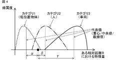
- FIG. 4 is a schematic diagram in the case where expressions having different degrees of belonging in the same situation are used.
- FIG. 3 shows the degree of attribution (vertical axis) over the entire feature amount (horizontal axis) in a distributed manner, and
- FIG. 4 shows representative values (for example, centroid value, median value, maximum value) in the range of each category. (Frequency).
- the method of creating the attribution database 15 is not limited to the above, and for example, the entire value range of each category may be represented in a rectangular shape. In addition, for the overlapping portion of each category, the value divided by the overlap number can be used as the attribution distribution of each category.
- the database area (memory) can be reduced.
- the attribution database 15 can be created by acquiring several samples (teacher data) of each category. For example, in order to obtain the attribution distribution shown in FIG. 3, after creating a histogram of a sample (teacher data), the maximum value can be normalized. In the example of FIG. 3, the attribution distribution is created for each relative distance R. However, by setting the relative distance finely (for example, 1 m), the characteristics for each distance can be finely reflected. It becomes possible. In addition, the area (memory) of the database can be reduced by collectively setting the relative distance to areas having similar characteristics of the secondary feature amount, for example, as far / near. The attribution distribution can also be created for each relative speed.
- the characteristic amount that captures changes at multiple observation points such as the amount of change in the received intensity value
- an attribution distribution should be created for each speed. Therefore, it is possible to cope with this, and the effect of reducing the deterioration of the object identification performance can be expected.
- the value of each category distribution ( ⁇ , ⁇ , ⁇ ) can be performed.
- the degree of attribution can be assigned by the distance between the secondary feature value and the representative value of the degree of attribution (or the reciprocal thereof).
- FIG. 5 shows a conceptual diagram of the object determination process.
- a coefficient wi is a weighting coefficient of each secondary feature amount determined in advance.
- the relative speed is added to the secondary feature amount.
- the determination result of the previous observation time or the determination result so far can be input as the secondary feature amount.
- the weight coefficient in the object determination process can be set according to the degree of influence on the determination of each secondary feature amount. For example, when the influence levels of all the secondary feature amounts are equal, the weight coefficients are all set to the same value (for example, 1). In addition, when the degree of influence of each secondary feature varies depending on the relative distance, it is possible to identify the object with higher accuracy by changing the weighting factor for each relative distance.
- the total value of each category can be considered as a ratio or reliability that belongs to each category of the object.
- interpretation of the determination result is facilitated by expressing the value normalized by the maximum value of the total sum or as a percentage.
- the predetermined total threshold value When the total value is less than the predetermined total threshold value, it is possible to output as an uncertain category that does not belong to the predetermined category. Further, when the difference between the highest total value and the next highest total value is less than a predetermined threshold value, it is possible to output that the determination is impossible because the category cannot be narrowed down to one.
- the indeterminate category is added as a new category in the subsequent processing, so that the database can be expanded and can be appropriately determined from the next time.
- all the secondary feature values are handled equally. For example, after determining the feature value having a high influence on a certain category in the first stage and narrowing down the category, the remaining categories It is also possible to make a determination. By performing such processing, the final determination accuracy can be improved.
- the radar signal processing apparatus extracts a feature quantity effective in distinguishing a vehicle, a person, or a low-position object, such as a change amount of a received intensity value, from the information of the radar alone (a remarkable difference). Since the category is determined, it is possible to identify the object with high accuracy without complicating the system configuration.
- the category is determined for each distance using the feature amount whose characteristic changes for each distance, it is possible to perform highly accurate object identification. That is, since the category (type) of the object is determined based on the measurement result for each distance of the object acquired by the radar, it is possible to identify the object with high accuracy regardless of the distance.
- the degree of attribution is calculated for each distance between the vehicle and the object.
- the category is determined based on the observation values of two or more observation periods, so that the determination immediacy can be improved.
- change_quantity of a received intensity value determination is possible in one observation period.
- the radar signal processing apparatus extracts and determines a plurality of feature amounts, the determination can be made even when the feature amounts cannot be obtained due to partial loss or the like.
- Embodiment 2 As a second embodiment in which the present invention is different, it is conceivable to create an attribution distribution for each radar mounting position of the host vehicle. As described above, the characteristics of the radar reflected wave differ depending on the altitude of the object and the mounting position (altitude) of the own vehicle radar, such as the presence or absence of multipath generation. Therefore, when the mounting position of the own vehicle radar changes depending on the vehicle type and other conditions, it is possible to make a determination with higher accuracy by using an attribution distribution (database) specialized for the mounting position.
- database attribution distribution
- the attribution distribution is created / changed for each position where the radar of the own vehicle is attached, so that more accurate object identification is performed. It is possible.
- the embodiments can be freely combined within the scope of the invention, and the embodiments can be appropriately changed or omitted.
Landscapes
- Engineering & Computer Science (AREA)
- Radar, Positioning & Navigation (AREA)
- Remote Sensing (AREA)
- Physics & Mathematics (AREA)
- Computer Networks & Wireless Communication (AREA)
- General Physics & Mathematics (AREA)
- Electromagnetism (AREA)
- Radar Systems Or Details Thereof (AREA)
Abstract
精度の高い物体識別を行う。一次特徴量抽出部11で抽出された物体との相対距離と相対速度並びに物体の方位と反射強度に関わる一次特徴量をデータ格納処理部12において時系列的に同一化を行い、二次特徴量抽出部13において二次特徴量を抽出し、帰属度算出部14で算出した所定のカテゴリに関する二次特徴量の分布に対する帰属度に基づき物体判定部16で物体のカテゴリを判定する。
Description
この発明は、車載用レーダ装置のレーダ信号処理装置に関するもので、特に反射物体を所定カテゴリに識別することにより、制動制御を行うべきか否かの判断を支援する技術に関する。
従来から、車載用レーダ装置によって測定される、自車と反射物体との相対距離、相対速度、方位、反射強度などの測定結果は、自車が前方の障害物に衝突した際の被害を軽減する衝突被害軽減ブレーキシステムや、前方の車両に追従するアダプティブクルーズコントロールシステムなど、車両の安全性や快適性を向上するための車載用アプリケーションで活用されている。
このようなアプリケーションでは、対象となる物体に関する測定結果そのもの、もしくは、測定結果から導出した新たな特徴量に基づき、制動すべきか否かを判定している。
例えば、特許文献1では、物標の電力分布(マルチパスによるヌルポイントの発生パターン)から、物標の路面からの高さを推定し、制動対象であるか否かを判定している。
また、特許文献2では、高さが既知である種々の物体を用いて予め作成した振幅パターン辞書(データベース)を照合することにより、物体の高さを推定している。
例えば、特許文献1では、物標の電力分布(マルチパスによるヌルポイントの発生パターン)から、物標の路面からの高さを推定し、制動対象であるか否かを判定している。
また、特許文献2では、高さが既知である種々の物体を用いて予め作成した振幅パターン辞書(データベース)を照合することにより、物体の高さを推定している。
異なる例として、特許文献3では、受信強度(レーダ反射断面積)及びFMCW(Frequency Modulated Continuous Wave)方式における周波数の上り区間と下り区間での受信強度差のばらつき(標準偏差)に基づき、対象が車両であるか否か、人間であるか否かの識別を行い、制動対象であるか否かを判定している。
従来の装置は上述のように構成されているので、特許文献1および特許文献2では、信号強度に由来する特徴量のみに基づいて判定を行うため、測定結果が正常に得られない場合には推定精度が劣化する課題がある。
また、特許文献2のように辞書を照合する方式では、精度の高い推定を行うための辞書を作成するのに膨大な数のデータ取得が必要であり、更に、照合には一般に高い演算負荷や大容量のメモリが必要となり、高コストになる課題がある。
また、特許文献3の方法では、事前に物体を識別することで、制動対象/非制動対象を絞り込むことができるため、最終的な判定精度向上が期待できるものの、レーダ反射断面積はビームパタン、物体の材質、姿勢、及び距離によって変わるため、安定した判定が困難と考えられ、また、ばらつきを算出するにはある程度のデータ蓄積が必要であるため、例えば、前方車両の急な車線変更といった時間的に余裕のない状況への対応が遅れる可能性が考えられる。
また、特許文献2のように辞書を照合する方式では、精度の高い推定を行うための辞書を作成するのに膨大な数のデータ取得が必要であり、更に、照合には一般に高い演算負荷や大容量のメモリが必要となり、高コストになる課題がある。
また、特許文献3の方法では、事前に物体を識別することで、制動対象/非制動対象を絞り込むことができるため、最終的な判定精度向上が期待できるものの、レーダ反射断面積はビームパタン、物体の材質、姿勢、及び距離によって変わるため、安定した判定が困難と考えられ、また、ばらつきを算出するにはある程度のデータ蓄積が必要であるため、例えば、前方車両の急な車線変更といった時間的に余裕のない状況への対応が遅れる可能性が考えられる。
この発明は上記のような課題を解決するためになされたもので、レーダ測定値から抽出した物体の特徴を用いて物体を識別し、精度の高い制動対象、非制動対象の判定が可能なレーダ信号処理装置を得ることを目的とする。
この発明のレーダ信号処理装置は、レーダの受信信号から一定時間周期で複数の物体について少なくとも物体との相対距離と相対速度並びに物体の方位と反射強度に関わる情報を一次特徴量として抽出する一次特徴量抽出部と、一次特徴量を格納し、複数の一次特徴量を複数の周期にわたって時系列で同一の物体であると関連付けるデータ格納処理部と、データ格納処理部における一次特徴量から二次特徴量を抽出する二次特徴量抽出部と、あらかじめ定められたカテゴリに関する前記二次特徴量の分布に対する帰属度を算出する帰属度算出部と、帰属度に基づき物体のカテゴリを判定する物体判定部を備えたものである。
この発明のレーダ信号処理装置は、レーダで取得した物体の反射強度の短時間の変化量を特徴量として当該物体のカテゴリ(種別)を判定するようにしたので、短時間もしくは少ない測定点から精度の高い物体識別することができる。
また、この発明のレーダ信号処理装置は、レーダで取得した物体の複数の特徴量に基づき当該物体のカテゴリ(種別)を判定するようにしたので、欠損等がある場合でも精度の高い物体識別をすることができる。
また、この発明のレーダ信号処理装置は、レーダで取得した物体の複数の特徴量に基づき当該物体のカテゴリ(種別)を判定するようにしたので、欠損等がある場合でも精度の高い物体識別をすることができる。
実施の形態1.
図1は、この発明の実施の形態1による車載用レーダ装置(「レーダ」とも称す)のレーダ信号処理装置を示す構成図である。
図1に示すレーダ信号処理装置10は、一次特徴量抽出部11、データ格納処理部12、二次特徴量抽出部13、帰属度算出部14、帰属度データベース15、物体判定部16を備えている。
なお、図示していない物体に電波を放射し、当該物体(「反射物体」とも称す)からの反射波を受ける部分及びその方式(FMCW 方式、FMICW 方式、パルスドップラー方式など)や、全体の制御を行う部分等については、一般的な車載用のレーダと同等のものであるため、説明を省略する。
図1は、この発明の実施の形態1による車載用レーダ装置(「レーダ」とも称す)のレーダ信号処理装置を示す構成図である。
図1に示すレーダ信号処理装置10は、一次特徴量抽出部11、データ格納処理部12、二次特徴量抽出部13、帰属度算出部14、帰属度データベース15、物体判定部16を備えている。
なお、図示していない物体に電波を放射し、当該物体(「反射物体」とも称す)からの反射波を受ける部分及びその方式(FMCW 方式、FMICW 方式、パルスドップラー方式など)や、全体の制御を行う部分等については、一般的な車載用のレーダと同等のものであるため、説明を省略する。
一次特徴量抽出部11は、得られた受信信号から、少なくとも物体に関する相対距離、相対速度、方位、反射強度を算出する。以降、これらを一次特徴量と称する。すなわち、レーダの受信信号から一定時間周期で複数の物体について少なくとも物体との相対距離と相対速度並びに前記物体の方位と反射強度に関わる情報を一次特徴量として抽出する。ただし、後段の判定処理で使用しない一次特徴量については必ずしも取得する必要はない。なお、反射物体が複数存在する場合は、複数物体に関する一次特徴量を算出する。また、一次特徴量における方位は、例えばESPRIT(Estimation of Signal Parameters via Rotational Invariance Techniques)や、MUSIC(MUltiple SIgnal Classification)といった公知の超分解能処理による出力結果を含む。また、一次特徴量は、所定の周期(例えば、100msec)で得られるものとする。
データ格納処理部12は、一次特徴量抽出部11より出力された一次特徴量を格納すると共に、格納された一次特徴量について、同一反射物に関するものには例えば同一ID(番号)を付す。すなわち、データ格納処理部12には、反射物毎に同一IDが付された一次特徴量(相対距離、相対速度、方位、受信強度)の時系列が格納される。すなわち、複数の一次特徴量を複数の周期にわたって時系列で同一の物体であると関連付ける。一次特徴量をデータ格納処理部12において時系列的に同一化を行うことになる。
二次特徴量抽出部13は、一次特徴量から、相対距離の最大値(最大検出距離)や、受信強度値や、受信強度値の変化量や、波数情報といった二次特徴量を算出する。
なお、受信強度値は、一次特徴量として得られる反射強度から、雑音やマルチパス等によって生じた急峻な変化を抑圧したものとすることができる。
また、受信強度値の変化量は、現観測値と一観測前の値との差(もしくは比)とすることができる。
また、波数情報は、波数推定の結果から、例えば、当該物体からの反射波数が1波か、もしくは、2波(複数)かとすることができる。
また、上記以外に、一次特徴量を用いて得られる他の特徴量とすることもでき、例えば、所定距離範囲内もしくは所定観測点内における受信強度値の標準偏差や、最大値や、最大値と最小値との差を加えることもできる。
なお、受信強度値は、一次特徴量として得られる反射強度から、雑音やマルチパス等によって生じた急峻な変化を抑圧したものとすることができる。
また、受信強度値の変化量は、現観測値と一観測前の値との差(もしくは比)とすることができる。
また、波数情報は、波数推定の結果から、例えば、当該物体からの反射波数が1波か、もしくは、2波(複数)かとすることができる。
また、上記以外に、一次特徴量を用いて得られる他の特徴量とすることもでき、例えば、所定距離範囲内もしくは所定観測点内における受信強度値の標準偏差や、最大値や、最大値と最小値との差を加えることもできる。
帰属度算出部14は、帰属度データベース15から得られる二次特徴量毎の帰属度分布に基づいて、二次特徴量抽出部13から入力される二次特徴量の各特徴量のカテゴリ(種別)毎の値(帰属度)を算出する。すなわち、あらかじめ定められたカテゴリに関する二次特徴量の分布に対する帰属度を算出する。
帰属度データベース15は、予め定めたカテゴリについて、予め数例の観測を行って取得した二次特徴量分布や、送信電力、距離、アンテナ利得、反射断面積等から導出した理論値に基づく二次特徴量分布や、カテゴリに関する経験的知見に基づく性質を数値化し格納する。
物体判定部16は、帰属度算出部14から入力された当該物体に関するカテゴリ毎の帰属度に基づき、当該物体がどのカテゴリに属するか、すなわち、当該物体の種別(例えば、車両、人、乗り越え可能な低位置物体等)を判定し、判定結果を出力する。
なお、判定結果はその後、図示しない制御部により、例えば、制動制御に用いられる。
なお、判定結果はその後、図示しない制御部により、例えば、制動制御に用いられる。
次に、動作について説明する。
まず、一次特徴量抽出部11において、所定観測周期毎に入力される受信信号を用いて、一次特徴量(相対距離、相対速度、方位、反射強度)を算出する。なお、本一次特徴量は、レーダにおいて相対距離、相対速度、方位、反射強度を算出する一般的な方式によるものであるため、詳細な説明を省略する。
まず、一次特徴量抽出部11において、所定観測周期毎に入力される受信信号を用いて、一次特徴量(相対距離、相対速度、方位、反射強度)を算出する。なお、本一次特徴量は、レーダにおいて相対距離、相対速度、方位、反射強度を算出する一般的な方式によるものであるため、詳細な説明を省略する。
次に、データ格納処理部12において、一次特徴量抽出部11から入力された一次特徴量を格納し、それまで格納されている過去の数観測分の一次特徴量と共に、例えばカルマンフィルタを用いた追尾処理により同一反射物に関するもの同士の対応付けを行い、同一反射物に対して同一ID(番号)及び、データの更新時刻を記した時刻タグもしくはデータの入力順序を記した順序タグを付す。なお、一次特徴量として取得した反射強度には、一般に、雑音やマルチパスによる急峻な変化が重畳しているため、後段において安定した判定結果を得るために、所定距離範囲もしくは所定観測点による移動平均を行う。
なお、データ格納処理部12において、例えば、同一IDの一次特徴量が更新(追加)されない状態が所定観測数に達した一次特徴量については、順次消去することで、データ格納処理部12のメモリ空間を節約することができる。
次に、二次特徴量抽出部13において、一次特徴量を用いて、最大検出距離や、受信強度値や、受信強度値の変化量や、波数情報といった二次特徴量を算出する。
最大検出距離は、目標の相対距離の最大値を表す特徴量である。一般に、車両や人などのようなある高さを持つ物体は遠距離から検出されるため、最大検出距離は大きい傾向を持つ。一方、乗り越え可能な低位置物体は比較的近距離で初めて検出されるため、最大検出距離は小さい傾向を持つ。
受信強度値は、物体の反射強度を表す特徴量である。一般に、同一距離においては、車両など高いレーダ反射断面積を持ち、かつ、金属等の材質の物体の反射強度値は高い。一方、人はレーダ反射断面積が車両に比べ小さいため、車両より反射強度値は小さいが、様々な姿勢を取ることが可能であるため、反射強度値の値域は大きい。また、例えば路面の継ぎ目やグレーチングなど乗り越え可能な低位置物体は、比較的遠距離では受信強度値は小さいが、近づくと、エッジ部分からの反射の影響が大きくなるため、受信強度値は比較的大きな値を持つ。
受信強度値の変化量は、受信強度値の現在及び直近の観測における受信強度値の差もしくは比で定義する特徴量である。図2は、距離変化における受信強度値の変化量を示す模式図である。一般に、物体に近づく状況(自車と物体との相対距離が小さくなる状況)において、車両の場合は、マルチパスによる急激な受信強度の変動を除くと、比較的受信強度値の変化量は小さいまま推移する。また、人の場合は、レーダ反射断面積が変化するため、受信強度値の変化量は車両よりも大きく推移する。また、乗り越え可能な低位置物体の場合は、遠距離では車両と同様に受信強度値の変化量は小さく推移し、ある距離から近づくとエッジ等の影響により大きくなる。
波数情報は、(超分解能)測角時に得られる、同一物体からの反射点の数や、方位を表す特徴量である。例えば、車両の場合、距離により反射点が1点もしくは複数点となり、かつ、反射点が明確に複数の場合(反射点が所定方位差を持つ場合)、反射点が明確ではない複数の場合(反射点の方位が近い、もしくは一方が測角不能など)といった状態となる。人や低位置物体の場合も同様であるが、このような状態は車両、人、低位置物体で異なることが予想される。波数情報はこのような各状態を例えば、1、2、・・・といった番号により表現する。
次に、帰属度算出部14において、抽出した二次特徴量の、各カテゴリ(例えば、車両、人、低位置物体)への帰属度を算出する。
帰属度算出には、予め作成した帰属度データベース15を用いる。
帰属度算出には、予め作成した帰属度データベース15を用いる。
帰属度データベース15は、所定のカテゴリについて、相対距離毎に二次特徴量の分布状況を表したものである。
図3は、ある二次特徴量の、ある相対距離Rにおいて、カテゴリをカテゴリ1(低位置物体)、カテゴリ2(人)、カテゴリ3(車両)とした場合の帰属度の模式図を示している。
また、図4は、同じ状況の帰属度の異なる表現を用いた場合の模式図を示している。
図3は、特徴量全体(横軸)に亘る帰属度(縦軸)を分布状に表したものであり、図4は、各カテゴリの値域における代表値(例えば、重心値、中央値、最頻値)で表したものである。
なお、帰属度データベース15の作成方法は以上に限らず、例えば、各カテゴリの値域全体を矩形状に表すこともできる。
また、各カテゴリの重複部分については、重複数で割った値を各カテゴリの帰属度分布とすることもできる。
帰属度データベース15を図4のような代表値で作成した場合は、データベースの領域(メモリ)を削減することができる。
図3は、ある二次特徴量の、ある相対距離Rにおいて、カテゴリをカテゴリ1(低位置物体)、カテゴリ2(人)、カテゴリ3(車両)とした場合の帰属度の模式図を示している。
また、図4は、同じ状況の帰属度の異なる表現を用いた場合の模式図を示している。
図3は、特徴量全体(横軸)に亘る帰属度(縦軸)を分布状に表したものであり、図4は、各カテゴリの値域における代表値(例えば、重心値、中央値、最頻値)で表したものである。
なお、帰属度データベース15の作成方法は以上に限らず、例えば、各カテゴリの値域全体を矩形状に表すこともできる。
また、各カテゴリの重複部分については、重複数で割った値を各カテゴリの帰属度分布とすることもできる。
帰属度データベース15を図4のような代表値で作成した場合は、データベースの領域(メモリ)を削減することができる。
帰属度データベース15は、各カテゴリのサンプル(教師データ)を数例取得することで作成が可能である。
例えば、図3の帰属度分布を得るには、サンプル(教師データ)のヒストグラムを作成したのち、最大値を規格化することで作成することができる。また、図3の例では相対距離R毎に帰属度分布を作成しているが、相対距離を細かく(例えば1m)設定することで距離毎の特性も細かく反映できるため、精度の高い物体識別が可能となる。また、相対距離を、二次特徴量が同じような特性を持つ領域をまとめて、例えば遠/近のように大きく設定することで、データベースの領域(メモリ)を削減することもできる。また、帰属度分布は、相対速度毎に作成することもできる。この場合には、受信強度値の変化量のように、複数の観測点の変化を捉える特徴量では、相対速度によって特性が異なることが予想されるが、速度毎に帰属度分布を作成することでそれに対応でき、物体識別性能の劣化を低減する効果が期待できる。
例えば、図3の帰属度分布を得るには、サンプル(教師データ)のヒストグラムを作成したのち、最大値を規格化することで作成することができる。また、図3の例では相対距離R毎に帰属度分布を作成しているが、相対距離を細かく(例えば1m)設定することで距離毎の特性も細かく反映できるため、精度の高い物体識別が可能となる。また、相対距離を、二次特徴量が同じような特性を持つ領域をまとめて、例えば遠/近のように大きく設定することで、データベースの領域(メモリ)を削減することもできる。また、帰属度分布は、相対速度毎に作成することもできる。この場合には、受信強度値の変化量のように、複数の観測点の変化を捉える特徴量では、相対速度によって特性が異なることが予想されるが、速度毎に帰属度分布を作成することでそれに対応でき、物体識別性能の劣化を低減する効果が期待できる。
帰属度算出においては、図3のような帰属度分布の場合には、二次特徴量が横軸上の黒点で示した値であるとき、その特徴量における各カテゴリ分布の値(α、β、γ)を割り当てることで、行うことができる。
また、図4のような帰属度の代表値の場合には、二次特徴量の値と、帰属度の代表値の距離(もしくは、その逆数)により、帰属度を割り当てることができる。
また、図4のような帰属度の代表値の場合には、二次特徴量の値と、帰属度の代表値の距離(もしくは、その逆数)により、帰属度を割り当てることができる。
次に、物体判定部16において、帰属度算出部14より入力された二次特徴量の帰属度に、二次特徴量の所定重み係数を掛け、総和を取った後、最も総和値が高いものを、当該物体のカテゴリとして出力する。
図5は、物体判定処理の概念図を示す。同図において、係数wiは 、予め定めた各二次特徴量の重み係数である。
なお、図5の構成では、相対速度を二次特徴量に加えている。また、二次特徴量として、前観測時刻の判定結果、もしくは、それまでに判定された結果を入力することもできる。この構成では、前回の判定結果を入力することにより、現在の観測値が欠損した場合や、雑音等により劣化した場合でも安定した判定結果を得ることができることの他、過去の判定結果を引き継ぐことになるため、より信頼性のある判定結果を得る効果が期待できる。
図5は、物体判定処理の概念図を示す。同図において、係数wiは 、予め定めた各二次特徴量の重み係数である。
なお、図5の構成では、相対速度を二次特徴量に加えている。また、二次特徴量として、前観測時刻の判定結果、もしくは、それまでに判定された結果を入力することもできる。この構成では、前回の判定結果を入力することにより、現在の観測値が欠損した場合や、雑音等により劣化した場合でも安定した判定結果を得ることができることの他、過去の判定結果を引き継ぐことになるため、より信頼性のある判定結果を得る効果が期待できる。
物体判定処理における重み係数は、各二次特徴量の判定に対する影響度に応じて設定することができる。
例えば、全ての二次特徴量の影響度が等しい場合は、重み係数を全て等しい値(例えば1)とする。
また、各二次特徴の影響度が相対距離に応じて異なる場合は、相対距離毎に重み係数を変えることでより精度の高い物体識別が可能となる。
例えば、全ての二次特徴量の影響度が等しい場合は、重み係数を全て等しい値(例えば1)とする。
また、各二次特徴の影響度が相対距離に応じて異なる場合は、相対距離毎に重み係数を変えることでより精度の高い物体識別が可能となる。
判定結果の出力の仕方としては、最も高い総和値のカテゴリを出力する方法の他に、全てのカテゴリの総和値を出力することも可能である。
この場合は、各カテゴリの総和値は、物体の各カテゴリに属する割合、もしくは、信頼度と考えることができる。なお、この場合は、総和値の最大値で規格化した値、もしくは百分率で表すことにより、判定結果の解釈が容易となる。
この場合は、各カテゴリの総和値は、物体の各カテゴリに属する割合、もしくは、信頼度と考えることができる。なお、この場合は、総和値の最大値で規格化した値、もしくは百分率で表すことにより、判定結果の解釈が容易となる。
また、総和値が所定の総和閾値に満たない場合は、所定のカテゴリに属さない、不確定なカテゴリとして出力することも可能である。また、最も高い総和値と次に高い総和値との差が所定閾値未満である場合は、カテゴリを一つに絞り込めないとして、判定不能と出力することも可能である。
このように不確定もしくは判定不能という出力を行うことで、信頼性がない状態で所定のカテゴリに分類分けして、結果的にカテゴリを誤り、判定精度を劣化させることを回避することができる。
このとき、不確定カテゴリは、次回以降の処理において新たなカテゴリとして付加することで、データベースの拡張ができ、次回以降に適切に判定することができる。
このように不確定もしくは判定不能という出力を行うことで、信頼性がない状態で所定のカテゴリに分類分けして、結果的にカテゴリを誤り、判定精度を劣化させることを回避することができる。
このとき、不確定カテゴリは、次回以降の処理において新たなカテゴリとして付加することで、データベースの拡張ができ、次回以降に適切に判定することができる。
なお、以上の実施の形態では、各二次特徴量を全て同等に扱っていたが、例えば、あるカテゴリへの影響度が高い特徴量について初段で判定し、カテゴリを絞り込んだ後、残りのカテゴリについて判定を行うことも可能である。
このような処理を行うことで、最終的な判定精度を向上させることができる。
このような処理を行うことで、最終的な判定精度を向上させることができる。
以上、本実施の形態によるレーダ信号処理装置では、レーダ単体の情報から受信強度値の変化量といった、車両や人や低位置物体の弁別において効果的な(差が顕著な)特徴量を抽出し、カテゴリを判定しているので、システム構成を複雑化させずに精度の高い物体識別を行うことが可能である。
また、本実施の形態によるレーダ信号処理装置では、距離毎に特性が変化する特徴量を用い、距離毎にカテゴリを判定しているので、精度の高い物体識別を行うことが可能である。すなわち、レーダで取得した物体の距離毎の測定結果に基づき当該物体のカテゴリ(種別)を判定するようにしたので、距離によらず精度の高い物体識別をすることができる。なお、帰属度算出において、自車と物体との距離毎に帰属度算出を行う。
また、本実施の形態によるレーダ信号処理装置では、2観測周期以上の観測値に基づきカテゴリを判定しているので、判定の即時性を向上させることが可能である。なお、受信強度値の変化量を使用しない場合は1観測周期で判定が可能である。
また、本実施の形態によるレーダ信号処理装置では、複数の特徴量を抽出して判定しているので、部分的に欠損等により特徴量が得られない場合でも、判定が可能である。
実施の形態2.
この発明の異なる実施の形態2として、自車のレーダ取り付け位置毎に、帰属度分布を作成することが考えられる。
上述のように、レーダ反射波は、物体の高度、自車レーダの取り付け位置(高度)により、例えばマルチパス発生の有無など、特性が異なる。
そのため、車種やその他の条件により自車レーダの取り付け位置が変わる場合には、その取り付け位置に特化した帰属度分布(データベース)を用いた方がより精度の高い判定ができる。
この発明の異なる実施の形態2として、自車のレーダ取り付け位置毎に、帰属度分布を作成することが考えられる。
上述のように、レーダ反射波は、物体の高度、自車レーダの取り付け位置(高度)により、例えばマルチパス発生の有無など、特性が異なる。
そのため、車種やその他の条件により自車レーダの取り付け位置が変わる場合には、その取り付け位置に特化した帰属度分布(データベース)を用いた方がより精度の高い判定ができる。
以上のように、本実施の形態2のレーダ信号処理装置によれば、自車のレーダの取り付け位置毎に帰属度分布を作成/変更するようにしているため、より精度の高い物体識別を行うことが可能である。
この発明は、その発明の範囲内において、各実施の形態を自由に組み合わせたり、各実施の形態を適宜、変更、省略することができる。
10 レーダ信号処理装置、11 一次特徴量抽出部、12 データ格納処理部、13 二次特徴量抽出部、14 帰属度算出部、16 物体判定部
Claims (10)
- 車両に搭載され、周辺に存在する複数の物体に関する情報を出力するレーダのレーダ信号処理装置において、レーダの受信信号から一定時間周期で複数の物体について少なくとも前記物体との相対距離と相対速度並びに前記物体の方位と反射強度に関わる情報を一次特徴量として抽出する一次特徴量抽出部と、前記一次特徴量を格納し、複数の一次特徴量を複数の周期にわたって時系列で同一の物体であると関連付けるデータ格納処理部と、前記データ格納処理部における一次特徴量から二次特徴量を抽出する二次特徴量抽出部と、あらかじめ定められたカテゴリに関する前記二次特徴量の分布に対する帰属度を算出する帰属度算出部と、前記帰属度に基づき物体のカテゴリを判定する物体判定部を備えたことを特徴とするレーダ信号処理装置。
- 二次特徴量として、前記物体の最大検出距離を抽出することを特徴とする請求項1記載のレーダ信号処理装置。
- 二次特徴量として、急激な変化を除去した受信強度値を抽出することを特徴とする請求項1記載のレーダ信号処理装置。
- 二次特徴量として、前記受信信号の受信強度値の変化量を抽出することを特徴とする請求項1記載のレーダ信号処理装置。
- 二次特徴量として、レーダによる測角時の波数情報を抽出することを特徴とする請求項1記載のレーダ信号処理装置。
- 帰属度算出において、自車と前記物体との距離毎に帰属度算出を行うことを特徴とする請求項1記載のレーダ信号処理装置。
- 物体判定において、あらかじめ定められた複数の各カテゴリについての前記帰属度の総和値を用いることを特徴とする請求項1記載のレーダ信号処理装置。
- 物体の判定において、前記帰属度とあらかじめ定められた重み係数を掛け合わせ総和をとった総和値に基づき、前記物体のカテゴリを判定することを特徴とする請求項1記載のレーダ信号処理装置。
- 物体判定において、前記総和値があらかじめ定められた閾値に満たない場合に、当該カテゴリについては判定不能とし、新たにカテゴリを追加することを特徴とする請求項7または請求項8記載のレーダ信号処理装置。
- レーダ取り付け高度位置毎に前記帰属度を変更することを特徴とする請求項1記載のレーダ信号処理装置。
Priority Applications (5)
| Application Number | Priority Date | Filing Date | Title |
|---|---|---|---|
| CN201580080067.3A CN107615090B (zh) | 2015-05-29 | 2015-05-29 | 雷达信号处理装置 |
| US15/569,444 US10663580B2 (en) | 2015-05-29 | 2015-05-29 | Radar signal processing device |
| PCT/JP2015/065529 WO2016194036A1 (ja) | 2015-05-29 | 2015-05-29 | レーダ信号処理装置 |
| EP15894071.8A EP3306340B1 (en) | 2015-05-29 | 2015-05-29 | Radar signal processing device |
| JP2015555467A JP5908193B1 (ja) | 2015-05-29 | 2015-05-29 | レーダ信号処理装置 |
Applications Claiming Priority (1)
| Application Number | Priority Date | Filing Date | Title |
|---|---|---|---|
| PCT/JP2015/065529 WO2016194036A1 (ja) | 2015-05-29 | 2015-05-29 | レーダ信号処理装置 |
Publications (1)
| Publication Number | Publication Date |
|---|---|
| WO2016194036A1 true WO2016194036A1 (ja) | 2016-12-08 |
Family
ID=55793188
Family Applications (1)
| Application Number | Title | Priority Date | Filing Date |
|---|---|---|---|
| PCT/JP2015/065529 Ceased WO2016194036A1 (ja) | 2015-05-29 | 2015-05-29 | レーダ信号処理装置 |
Country Status (5)
| Country | Link |
|---|---|
| US (1) | US10663580B2 (ja) |
| EP (1) | EP3306340B1 (ja) |
| JP (1) | JP5908193B1 (ja) |
| CN (1) | CN107615090B (ja) |
| WO (1) | WO2016194036A1 (ja) |
Cited By (3)
| Publication number | Priority date | Publication date | Assignee | Title |
|---|---|---|---|---|
| JP2018173285A (ja) * | 2017-03-31 | 2018-11-08 | 学校法人慶應義塾 | 行動認識システム、及び行動認識方法 |
| JP2018197710A (ja) * | 2017-05-24 | 2018-12-13 | 三菱電機株式会社 | レーダ信号処理装置 |
| WO2025083837A1 (ja) * | 2023-10-19 | 2025-04-24 | 三菱電機株式会社 | レーダ信号処理装置、レーダ信号処理方法、レーダ信号処理プログラム、および記録媒体 |
Families Citing this family (14)
| Publication number | Priority date | Publication date | Assignee | Title |
|---|---|---|---|---|
| JP6223504B1 (ja) * | 2016-05-18 | 2017-11-01 | 三菱電機株式会社 | レーダ装置およびこれを用いたセンサフュージョン装置 |
| JP6319361B2 (ja) * | 2016-05-26 | 2018-05-09 | マツダ株式会社 | 車両用歩行者検出装置 |
| JP2018059884A (ja) * | 2016-10-07 | 2018-04-12 | 日本無線株式会社 | 物標識別装置、プログラム及び方法 |
| US11200882B2 (en) * | 2017-07-03 | 2021-12-14 | Nec Corporation | Signal processing device, signal processing method, and storage medium for storing program |
| JP6570675B2 (ja) | 2018-02-15 | 2019-09-04 | 三菱電機株式会社 | レーダ信号処理装置 |
| CN110361710A (zh) * | 2018-04-09 | 2019-10-22 | 北京京东尚科信息技术有限公司 | 基于激光点云的物体识别方法和装置 |
| JP2020016572A (ja) * | 2018-07-26 | 2020-01-30 | 日立オートモティブシステムズ株式会社 | レーダセンサ |
| CN109407703A (zh) * | 2018-12-13 | 2019-03-01 | 广州极飞科技有限公司 | 无人机及其控制方法和装置 |
| WO2020258253A1 (zh) * | 2019-06-28 | 2020-12-30 | 深圳市大疆创新科技有限公司 | 一种物体识别方法、毫米波雷达及车辆 |
| GB201919450D0 (en) | 2019-12-31 | 2020-02-12 | Essence Smartcare Ltd | A device for monitoring an environment |
| GB201919449D0 (en) * | 2019-12-31 | 2020-02-12 | Essence Smartcare Ltd | State detection |
| JP7367585B2 (ja) * | 2020-03-30 | 2023-10-24 | 株式会社アイシン | 物体検出システム |
| CN111429791B (zh) * | 2020-04-09 | 2022-11-18 | 浙江大华技术股份有限公司 | 身份确定方法、装置、存储介质及电子装置 |
| KR20220010900A (ko) * | 2020-07-20 | 2022-01-27 | 현대모비스 주식회사 | 차량용 레이더 장치 및 제어방법 |
Citations (6)
| Publication number | Priority date | Publication date | Assignee | Title |
|---|---|---|---|---|
| JPH10206531A (ja) * | 1997-01-17 | 1998-08-07 | Fujitsu Ten Ltd | 車両のレーダ装置 |
| JP2004191131A (ja) * | 2002-12-10 | 2004-07-08 | Denso Corp | 物標識別方法及び装置、プログラム |
| JP2004361154A (ja) * | 2003-06-03 | 2004-12-24 | Fujitsu Ten Ltd | 目標物判別装置 |
| WO2006025453A1 (ja) * | 2004-09-01 | 2006-03-09 | Matsushita Electric Industrial Co., Ltd. | レーダ装置 |
| JP2009031053A (ja) * | 2007-07-25 | 2009-02-12 | Fujitsu Ten Ltd | 前方障害物検出装置 |
| JP2013238452A (ja) * | 2012-05-14 | 2013-11-28 | Honda Elesys Co Ltd | 位置情報検出装置、位置情報検出方法、位置情報検出プログラム、及び動作制御システム |
Family Cites Families (26)
| Publication number | Priority date | Publication date | Assignee | Title |
|---|---|---|---|---|
| JP3401913B2 (ja) * | 1994-05-26 | 2003-04-28 | 株式会社デンソー | 車両用障害物認識装置 |
| JP2826494B2 (ja) * | 1995-11-21 | 1998-11-18 | 防衛庁技術研究本部長 | 目標信号検出方法及び装置 |
| SE511061C2 (sv) * | 1997-11-21 | 1999-07-26 | Celsiustech Electronics Ab | Förfarande för klassificering av upphöjda objekt |
| JP3512066B2 (ja) * | 1998-12-10 | 2004-03-29 | トヨタ自動車株式会社 | 車載用レーダ装置 |
| JP4115638B2 (ja) * | 1999-10-19 | 2008-07-09 | 本田技研工業株式会社 | 物体認識装置 |
| GB0017989D0 (en) * | 2000-07-24 | 2001-08-08 | Secr Defence | Target recognition system |
| JP3871875B2 (ja) * | 2000-11-06 | 2007-01-24 | 日本電気株式会社 | 目標類別方法及び装置 |
| DE102004047087A1 (de) * | 2004-09-29 | 2006-03-30 | Robert Bosch Gmbh | Verfahren zur Objektverifaktion in Radarsystemen für Kraftfahrzeuge |
| DE102005024716B4 (de) * | 2005-05-30 | 2023-09-21 | Robert Bosch Gmbh | Verfahren und Vorrichtung zur Erkennung und Klassifizierung von Objekten |
| US20070253625A1 (en) * | 2006-04-28 | 2007-11-01 | Bbnt Solutions Llc | Method for building robust algorithms that classify objects using high-resolution radar signals |
| JP4211809B2 (ja) * | 2006-06-30 | 2009-01-21 | トヨタ自動車株式会社 | 物体検出装置 |
| US7623061B2 (en) * | 2006-11-15 | 2009-11-24 | Autoliv Asp | Method and apparatus for discriminating with respect to low elevation target objects |
| CN101178773B (zh) | 2007-12-13 | 2010-08-11 | 北京中星微电子有限公司 | 基于特征提取和分类器的图像识别系统及方法 |
| JP4905512B2 (ja) * | 2009-07-09 | 2012-03-28 | 株式会社デンソー | 物標情報推定装置 |
| US8854251B2 (en) * | 2010-06-16 | 2014-10-07 | Toyota Jidosha Kabushiki Kaisha | Object identification device and method |
| JP2013002927A (ja) * | 2011-06-15 | 2013-01-07 | Honda Elesys Co Ltd | 障害物検知装置及びコンピュータプログラム |
| JP5852456B2 (ja) * | 2012-01-30 | 2016-02-03 | トヨタ自動車株式会社 | 周辺物体検知装置 |
| JP5926069B2 (ja) * | 2012-02-20 | 2016-05-25 | トヨタ自動車株式会社 | 障害物判定装置 |
| DE102012107445B8 (de) * | 2012-08-14 | 2016-04-28 | Jenoptik Robot Gmbh | Verfahren zur Klassifizierung von fahrenden Fahrzeugen |
| DE102012107444B3 (de) * | 2012-08-14 | 2013-03-07 | Jenoptik Robot Gmbh | Verfahren zur Klassifizierung von fahrenden Fahrzeugen durch Verfolgung einer Positionsgröße des Fahrzeuges |
| JP6212860B2 (ja) | 2012-12-27 | 2017-10-18 | 株式会社デンソー | 車載レーダ装置 |
| JP6205729B2 (ja) * | 2013-01-21 | 2017-10-04 | 株式会社デンソー | レーダ装置 |
| JP6369035B2 (ja) * | 2013-02-05 | 2018-08-08 | 株式会社デンソー | 物標検出装置 |
| JP6170704B2 (ja) | 2013-03-29 | 2017-07-26 | 富士通テン株式会社 | レーダ装置、および、信号処理方法 |
| US20150378014A1 (en) * | 2013-08-07 | 2015-12-31 | Sandia Corporation | Ascertaining class of a vehicle captured in an image |
| US9664779B2 (en) * | 2014-07-03 | 2017-05-30 | GM Global Technology Operations LLC | Object classification for vehicle radar systems |
-
2015
- 2015-05-29 US US15/569,444 patent/US10663580B2/en active Active
- 2015-05-29 CN CN201580080067.3A patent/CN107615090B/zh not_active Expired - Fee Related
- 2015-05-29 JP JP2015555467A patent/JP5908193B1/ja active Active
- 2015-05-29 WO PCT/JP2015/065529 patent/WO2016194036A1/ja not_active Ceased
- 2015-05-29 EP EP15894071.8A patent/EP3306340B1/en active Active
Patent Citations (6)
| Publication number | Priority date | Publication date | Assignee | Title |
|---|---|---|---|---|
| JPH10206531A (ja) * | 1997-01-17 | 1998-08-07 | Fujitsu Ten Ltd | 車両のレーダ装置 |
| JP2004191131A (ja) * | 2002-12-10 | 2004-07-08 | Denso Corp | 物標識別方法及び装置、プログラム |
| JP2004361154A (ja) * | 2003-06-03 | 2004-12-24 | Fujitsu Ten Ltd | 目標物判別装置 |
| WO2006025453A1 (ja) * | 2004-09-01 | 2006-03-09 | Matsushita Electric Industrial Co., Ltd. | レーダ装置 |
| JP2009031053A (ja) * | 2007-07-25 | 2009-02-12 | Fujitsu Ten Ltd | 前方障害物検出装置 |
| JP2013238452A (ja) * | 2012-05-14 | 2013-11-28 | Honda Elesys Co Ltd | 位置情報検出装置、位置情報検出方法、位置情報検出プログラム、及び動作制御システム |
Non-Patent Citations (1)
| Title |
|---|
| See also references of EP3306340A4 * |
Cited By (6)
| Publication number | Priority date | Publication date | Assignee | Title |
|---|---|---|---|---|
| JP2018173285A (ja) * | 2017-03-31 | 2018-11-08 | 学校法人慶應義塾 | 行動認識システム、及び行動認識方法 |
| JP7150292B2 (ja) | 2017-03-31 | 2022-10-11 | 慶應義塾 | 行動認識システム、及び行動認識方法 |
| JP2018197710A (ja) * | 2017-05-24 | 2018-12-13 | 三菱電機株式会社 | レーダ信号処理装置 |
| US10663561B2 (en) | 2017-05-24 | 2020-05-26 | Mitsubishi Electric Corporation | Radar signal processing device |
| WO2025083837A1 (ja) * | 2023-10-19 | 2025-04-24 | 三菱電機株式会社 | レーダ信号処理装置、レーダ信号処理方法、レーダ信号処理プログラム、および記録媒体 |
| JP7717307B1 (ja) * | 2023-10-19 | 2025-08-01 | 三菱電機株式会社 | レーダ信号処理装置、レーダ信号処理方法、レーダ信号処理プログラム、および記録媒体 |
Also Published As
| Publication number | Publication date |
|---|---|
| US10663580B2 (en) | 2020-05-26 |
| EP3306340A1 (en) | 2018-04-11 |
| JPWO2016194036A1 (ja) | 2017-06-22 |
| EP3306340A4 (en) | 2019-01-23 |
| CN107615090B (zh) | 2021-06-11 |
| CN107615090A (zh) | 2018-01-19 |
| EP3306340B1 (en) | 2021-06-23 |
| US20180081052A1 (en) | 2018-03-22 |
| JP5908193B1 (ja) | 2016-04-26 |
Similar Documents
| Publication | Publication Date | Title |
|---|---|---|
| JP5908193B1 (ja) | レーダ信号処理装置 | |
| JP6570675B2 (ja) | レーダ信号処理装置 | |
| EP3663790B1 (en) | Method and apparatus for processing radar data | |
| KR102099851B1 (ko) | 자동차 레이더 시스템에서 탐지된 타겟들의 클러스터링 방법 및 이를 위한 장치 | |
| JP6223504B1 (ja) | レーダ装置およびこれを用いたセンサフュージョン装置 | |
| US12005907B2 (en) | Method for determining position data and/or motion data of a vehicle | |
| KR101628154B1 (ko) | 수신 신호 세기를 이용한 다중 표적 추적 방법 | |
| CN113536850B (zh) | 基于77g毫米波雷达的目标物体大小测试方法和装置 | |
| CN109154655A (zh) | 目标信号检测方法、设备、无人机及农业无人机 | |
| CN116964472A (zh) | 用于借助于雷达传感器系统的反射信号来探测环境的至少一个对象的方法 | |
| Park et al. | Bidirectional LSTM-based overhead target classification for automotive radar systems | |
| CN112034464B (zh) | 一种目标分类方法 | |
| CN117192537A (zh) | 一种基于超宽带雷达技术的高速运动目标变点检测跟踪方法 | |
| KR101426290B1 (ko) | 레이더 시스템 및 이를 이용한 표적 추적 방법 | |
| Park et al. | Ground reflection-based misalignment detection of automotive radar sensors | |
| CN119439090A (zh) | 使用先前被跟踪对象信息的改进的雷达检测 | |
| RU157396U1 (ru) | Устройство распознавания винтовых летательных аппаратов | |
| JP7717307B1 (ja) | レーダ信号処理装置、レーダ信号処理方法、レーダ信号処理プログラム、および記録媒体 | |
| JP2005114416A (ja) | 擾乱検出装置 | |
| CN118033671B (zh) | 基于车载激光雷达的道路巡检方法及相关装置 | |
| US12140657B2 (en) | Directly determining free spaces around devices | |
| US20240418847A1 (en) | Method for estimating position of target object, non-transitory computer readable storage medium, and target object position estimation device | |
| JP2020046218A (ja) | レーダ装置および物標判別方法 | |
| CN120820948A (zh) | 障碍物识别方法、装置、电子设备及计算机存储介质 | |
| CN120724185A (zh) | 一种基于毫米波交通雷达的动态多维快速航迹关联方法及装置 |
Legal Events
| Date | Code | Title | Description |
|---|---|---|---|
| ENP | Entry into the national phase |
Ref document number: 2015555467 Country of ref document: JP Kind code of ref document: A |
|
| 121 | Ep: the epo has been informed by wipo that ep was designated in this application |
Ref document number: 15894071 Country of ref document: EP Kind code of ref document: A1 |
|
| WWE | Wipo information: entry into national phase |
Ref document number: 15569444 Country of ref document: US |
|
| NENP | Non-entry into the national phase |
Ref country code: DE |