WO2016194207A1 - Actionneur électromagnétique - Google Patents
Actionneur électromagnétique Download PDFInfo
- Publication number
- WO2016194207A1 WO2016194207A1 PCT/JP2015/066233 JP2015066233W WO2016194207A1 WO 2016194207 A1 WO2016194207 A1 WO 2016194207A1 JP 2015066233 W JP2015066233 W JP 2015066233W WO 2016194207 A1 WO2016194207 A1 WO 2016194207A1
- Authority
- WO
- WIPO (PCT)
- Prior art keywords
- sensor
- magnetic
- core
- electromagnetic actuator
- magnetic flux
- Prior art date
- Legal status (The legal status is an assumption and is not a legal conclusion. Google has not performed a legal analysis and makes no representation as to the accuracy of the status listed.)
- Ceased
Links
Images





Classifications
-
- G—PHYSICS
- G01—MEASURING; TESTING
- G01D—MEASURING NOT SPECIALLY ADAPTED FOR A SPECIFIC VARIABLE; ARRANGEMENTS FOR MEASURING TWO OR MORE VARIABLES NOT COVERED IN A SINGLE OTHER SUBCLASS; TARIFF METERING APPARATUS; MEASURING OR TESTING NOT OTHERWISE PROVIDED FOR
- G01D5/00—Mechanical means for transferring the output of a sensing member; Means for converting the output of a sensing member to another variable where the form or nature of the sensing member does not constrain the means for converting; Transducers not specially adapted for a specific variable
- G01D5/12—Mechanical means for transferring the output of a sensing member; Means for converting the output of a sensing member to another variable where the form or nature of the sensing member does not constrain the means for converting; Transducers not specially adapted for a specific variable using electric or magnetic means
- G01D5/14—Mechanical means for transferring the output of a sensing member; Means for converting the output of a sensing member to another variable where the form or nature of the sensing member does not constrain the means for converting; Transducers not specially adapted for a specific variable using electric or magnetic means influencing the magnitude of a current or voltage
- G01D5/20—Mechanical means for transferring the output of a sensing member; Means for converting the output of a sensing member to another variable where the form or nature of the sensing member does not constrain the means for converting; Transducers not specially adapted for a specific variable using electric or magnetic means influencing the magnitude of a current or voltage by varying inductance, e.g. by a movable armature
- G01D5/2006—Mechanical means for transferring the output of a sensing member; Means for converting the output of a sensing member to another variable where the form or nature of the sensing member does not constrain the means for converting; Transducers not specially adapted for a specific variable using electric or magnetic means influencing the magnitude of a current or voltage by varying inductance, e.g. by a movable armature by influencing the self-induction of one or more coils
-
- F—MECHANICAL ENGINEERING; LIGHTING; HEATING; WEAPONS; BLASTING
- F01—MACHINES OR ENGINES IN GENERAL; ENGINE PLANTS IN GENERAL; STEAM ENGINES
- F01L—CYCLICALLY OPERATING VALVES FOR MACHINES OR ENGINES
- F01L13/00—Modifications of valve-gear to facilitate reversing, braking, starting, changing compression ratio, or other specific operations
- F01L13/0015—Modifications of valve-gear to facilitate reversing, braking, starting, changing compression ratio, or other specific operations for optimising engine performances by modifying valve lift according to various working parameters, e.g. rotational speed, load, torque
- F01L13/0036—Modifications of valve-gear to facilitate reversing, braking, starting, changing compression ratio, or other specific operations for optimising engine performances by modifying valve lift according to various working parameters, e.g. rotational speed, load, torque the valves being driven by two or more cams with different shape, size or timing or a single cam profiled in axial and radial direction
-
- G—PHYSICS
- G01—MEASURING; TESTING
- G01B—MEASURING LENGTH, THICKNESS OR SIMILAR LINEAR DIMENSIONS; MEASURING ANGLES; MEASURING AREAS; MEASURING IRREGULARITIES OF SURFACES OR CONTOURS
- G01B7/00—Measuring arrangements characterised by the use of electric or magnetic techniques
-
- G—PHYSICS
- G01—MEASURING; TESTING
- G01B—MEASURING LENGTH, THICKNESS OR SIMILAR LINEAR DIMENSIONS; MEASURING ANGLES; MEASURING AREAS; MEASURING IRREGULARITIES OF SURFACES OR CONTOURS
- G01B7/00—Measuring arrangements characterised by the use of electric or magnetic techniques
- G01B7/02—Measuring arrangements characterised by the use of electric or magnetic techniques for measuring length, width or thickness
- G01B7/04—Measuring arrangements characterised by the use of electric or magnetic techniques for measuring length, width or thickness specially adapted for measuring length or width of objects while moving
-
- G—PHYSICS
- G01—MEASURING; TESTING
- G01D—MEASURING NOT SPECIALLY ADAPTED FOR A SPECIFIC VARIABLE; ARRANGEMENTS FOR MEASURING TWO OR MORE VARIABLES NOT COVERED IN A SINGLE OTHER SUBCLASS; TARIFF METERING APPARATUS; MEASURING OR TESTING NOT OTHERWISE PROVIDED FOR
- G01D5/00—Mechanical means for transferring the output of a sensing member; Means for converting the output of a sensing member to another variable where the form or nature of the sensing member does not constrain the means for converting; Transducers not specially adapted for a specific variable
- G01D5/12—Mechanical means for transferring the output of a sensing member; Means for converting the output of a sensing member to another variable where the form or nature of the sensing member does not constrain the means for converting; Transducers not specially adapted for a specific variable using electric or magnetic means
- G01D5/14—Mechanical means for transferring the output of a sensing member; Means for converting the output of a sensing member to another variable where the form or nature of the sensing member does not constrain the means for converting; Transducers not specially adapted for a specific variable using electric or magnetic means influencing the magnitude of a current or voltage
- G01D5/142—Mechanical means for transferring the output of a sensing member; Means for converting the output of a sensing member to another variable where the form or nature of the sensing member does not constrain the means for converting; Transducers not specially adapted for a specific variable using electric or magnetic means influencing the magnitude of a current or voltage using Hall-effect devices
- G01D5/145—Mechanical means for transferring the output of a sensing member; Means for converting the output of a sensing member to another variable where the form or nature of the sensing member does not constrain the means for converting; Transducers not specially adapted for a specific variable using electric or magnetic means influencing the magnitude of a current or voltage using Hall-effect devices influenced by the relative movement between the Hall device and magnetic fields
-
- H—ELECTRICITY
- H01—ELECTRIC ELEMENTS
- H01F—MAGNETS; INDUCTANCES; TRANSFORMERS; SELECTION OF MATERIALS FOR THEIR MAGNETIC PROPERTIES
- H01F7/00—Magnets
- H01F7/06—Electromagnets; Actuators including electromagnets
- H01F7/08—Electromagnets; Actuators including electromagnets with armatures
- H01F7/16—Rectilinearly-movable armatures
- H01F7/1607—Armatures entering the winding
-
- F—MECHANICAL ENGINEERING; LIGHTING; HEATING; WEAPONS; BLASTING
- F01—MACHINES OR ENGINES IN GENERAL; ENGINE PLANTS IN GENERAL; STEAM ENGINES
- F01L—CYCLICALLY OPERATING VALVES FOR MACHINES OR ENGINES
- F01L13/00—Modifications of valve-gear to facilitate reversing, braking, starting, changing compression ratio, or other specific operations
- F01L13/0015—Modifications of valve-gear to facilitate reversing, braking, starting, changing compression ratio, or other specific operations for optimising engine performances by modifying valve lift according to various working parameters, e.g. rotational speed, load, torque
- F01L13/0036—Modifications of valve-gear to facilitate reversing, braking, starting, changing compression ratio, or other specific operations for optimising engine performances by modifying valve lift according to various working parameters, e.g. rotational speed, load, torque the valves being driven by two or more cams with different shape, size or timing or a single cam profiled in axial and radial direction
- F01L2013/0052—Modifications of valve-gear to facilitate reversing, braking, starting, changing compression ratio, or other specific operations for optimising engine performances by modifying valve lift according to various working parameters, e.g. rotational speed, load, torque the valves being driven by two or more cams with different shape, size or timing or a single cam profiled in axial and radial direction with cams provided on an axially slidable sleeve
-
- F—MECHANICAL ENGINEERING; LIGHTING; HEATING; WEAPONS; BLASTING
- F01—MACHINES OR ENGINES IN GENERAL; ENGINE PLANTS IN GENERAL; STEAM ENGINES
- F01L—CYCLICALLY OPERATING VALVES FOR MACHINES OR ENGINES
- F01L13/00—Modifications of valve-gear to facilitate reversing, braking, starting, changing compression ratio, or other specific operations
- F01L2013/10—Auxiliary actuators for variable valve timing
- F01L2013/101—Electromagnets
-
- F—MECHANICAL ENGINEERING; LIGHTING; HEATING; WEAPONS; BLASTING
- F01—MACHINES OR ENGINES IN GENERAL; ENGINE PLANTS IN GENERAL; STEAM ENGINES
- F01L—CYCLICALLY OPERATING VALVES FOR MACHINES OR ENGINES
- F01L13/00—Modifications of valve-gear to facilitate reversing, braking, starting, changing compression ratio, or other specific operations
- F01L2013/11—Sensors for variable valve timing
-
- F—MECHANICAL ENGINEERING; LIGHTING; HEATING; WEAPONS; BLASTING
- F01—MACHINES OR ENGINES IN GENERAL; ENGINE PLANTS IN GENERAL; STEAM ENGINES
- F01L—CYCLICALLY OPERATING VALVES FOR MACHINES OR ENGINES
- F01L2301/00—Using particular materials
Definitions
- the present invention relates to an electromagnetic actuator capable of detecting the position of a plunger that is a mover.
- the electromagnetic actuator described in Patent Document 1 includes a coil that is a magnetomotive force generation source, a yoke that is a magnetic path, a core that is a mover, a plug nut that can be engaged with the core, and a core that is separated from the plug nut. And a large magnet and a small magnet that generate magnetic fluxes in opposite directions to the yoke, and a magnetic sensor that detects the direction of the magnetic flux flowing through the yoke.
- the core In the initial state, the core is urged by the spring and held in the initial position away from the plug nut.
- the magnetic flux from the large magnet In this initial state, the magnetic flux from the large magnet is dominant in the magnetic flux flowing through the yoke near the magnetic sensor, and the magnetic sensor detects the direction of the magnetic flux from the large magnet.
- the magnetic flux from the large magnet bypasses the yoke near the magnetic sensor and flows through the plug nut and the core.
- the magnetic flux flowing through the yoke near the magnetic sensor is dominated by the magnetic flux from the small magnet, and the magnetic sensor detects the direction of the magnetic flux from the small magnet.
- the position of the core relative to the plug nut can be determined by detecting the change in the direction of the magnetic flux flowing through the yoke by the magnetic sensor.
- Some electromagnetic actuators are used, for example, to switch between a high cam and a low cam of a camshaft in order to adjust the lift amount of an intake or exhaust valve in an internal combustion engine.
- This electromagnetic actuator is configured to operate two shafts with two movers. Switching from high cam to low cam by operating one shaft and switching from low cam to high cam by operating the other shaft Switch to.
- the position detection function of Patent Document 1 is applied to such an electromagnetic actuator having two movers, in order to detect the positions of the two movers, two sets of magnets and two A magnetic sensor is required.
- the present invention has been made to solve the above-described problems, and an object thereof is to detect the positions of a plurality of movers provided in an electromagnetic actuator using a single magnetic sensor.
- the electromagnetic actuator according to the present invention includes a magnetic plunger, a spring that biases the plunger in one direction, a magnetic core, and a magnetic flux that moves the plunger in a direction opposite to the biasing direction of the spring.
- An electromagnetic actuator comprising a plurality of sets of coils to be generated, a sensor magnet arranged in correspondence with each of the plungers, a magnetic sensor core arranged at a position where the magnetic flux of the plurality of sensor magnets can flow, and a sensor core And a magnetic sensor that is installed in a portion where the magnetic fluxes of the plurality of sensor magnets can flow in common and detects magnetic fluxes that change according to the movement positions of the plurality of plungers.
- the magnetic sensor installed in the part where the magnetic fluxes of the plurality of sensor magnets can flow in common in the sensor core, the magnetic flux that changes according to the movement position of the plurality of plungers is detected.
- the position of the plunger can be detected using one magnetic sensor.
- FIG. 1A is a plan view and FIG. 1B is a cross-sectional view showing a configuration example of an electromagnetic actuator according to Embodiment 1 of the present invention.
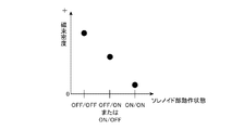
- 4 is a graph schematically showing a relationship between an operation state of two sets of solenoid units and a magnetic flux density detected by a magnetic sensor in the electromagnetic actuator according to the first embodiment.
- FIG. 3A is a plan view
- FIG. 3B and FIG. 3C are front views, illustrating a configuration example of a position detection unit of an electromagnetic actuator according to Embodiment 2 of the present invention.
- FIG. 10 is a plan view schematically showing the operating state of two sets of solenoid parts in the electromagnetic actuator according to the second embodiment.
- FIG. 10 is a plan view showing a modification of the position detection unit of the electromagnetic actuator according to Embodiment 2.
- FIG. It is a top view which shows the structural example of the position detection part of the electromagnetic actuator which concerns on Embodiment 3 of this invention.
- 9 is a graph schematically showing the relationship between the operating state of two sets of solenoid units and the magnetic flux density detected by a magnetic sensor in the electromagnetic actuator according to the third embodiment.
- 10 is a graph schematically showing the relationship between the operating states of two sets of solenoid units and the magnetic flux density detected by the magnetic sensor when sensor magnets having different magnetic forces are used in the electromagnetic actuator according to the third embodiment.
- It is a front view which shows the structural example of the position detection part of the electromagnetic actuator which concerns on Embodiment 4 of this invention.
- FIG. 10A is a plan view and FIG. 10B is a cross-sectional view showing an example of the configuration of an electromagnetic actuator according to Embodiment 5 of the present invention.
- FIG. 10 is a plan view illustrating a configuration example of a position detection unit of an electromagnetic actuator according to a fifth embodiment.
- FIG. 10 is a plan view illustrating a modification of the position detection unit of the electromagnetic actuator according to the fifth embodiment.
- FIG. 1A and 1B show a configuration example of an electromagnetic actuator 1 according to Embodiment 1 of the present invention.
- FIG. 1A is a plan view and FIG. 1B is a cross-sectional view.
- the position detector 20 is exposed by removing the case 3.
- the direction in which two sets of solenoid parts 10a and 10b are arranged is the X-axis direction
- the direction in which the plungers 11a and 11b move is the Y-axis direction
- the direction orthogonal to the X-axis and Y-axis The Z axis direction.
- the side where the cores 13a, 13b are installed is called the upper side
- the side where the bosses 15a, 15b are installed is called the lower side.
- the electromagnetic actuator 1 is accommodated in cases 2, 3 and 4 made of resin or the like.
- the electromagnetic actuator 1 includes two sets of solenoid portions 10a and 10b.
- the solenoid 10a includes a magnetic plunger 11a, a spring 12a for urging the plunger 11a upward in the Y-axis direction, a magnetic core 13a, and a lower side in the Y-axis direction opposite to the urging direction of the spring 12a.
- a coil 14a for generating magnetic flux in the core 13a for moving the plunger 11a.
- the case 2 has a magnetic yoke 5 embedded therein.
- a coil 14 a is fixed inside the case 2.
- the plunger 11a is slidably held by a cylindrical core 13a and a boss 15a arranged inside the coil 14a.
- the magnetic circuit of the solenoid unit 10a includes a coil 14a serving as a magnetomotive force source, a core 13a serving as a magnetic path, a boss 15a, and a yoke 5.
- the core 13a, the boss 15a, the yoke 5, and the coil 14a are stators.
- the plunger 11a which is a mover, is formed in a cylindrical shape, and a spring 12a and a pin 16a are installed therein.
- a shaft 18a is attached to the lower end of the pin 16a via a link 17a.
- a sensor magnet 21a is installed on the upper end surface of the plunger 11a. When the plunger 11a moves up and down, the sensor magnet 21a, the pin 16a, the link 17a and the shaft 18a also move up and down.
- the solenoid unit 10b has the same configuration as the solenoid unit 10a, and includes a plunger 11b, a spring 12b, a core 13b, and a coil 14b.
- the plunger 11b is provided with a sensor magnet 21b and a pin 16b. When the plunger 11b moves up and down, the sensor magnet 21b, the pin 16b, and a shaft 18b attached to the pin 16b via a link 17b are also provided. Move up and down.
- the upper surface of the case 2 is provided with a magnetic sensor core 22 through which the magnetic fluxes of the sensor magnets 21a and 21b can flow in common, and a magnetic sensor 23 for detecting the magnetic flux flowing through the sensor core 22.
- the magnetic sensor 23 is interposed in an air gap formed in the middle of the sensor core 22.
- the sensor magnets 21a and 21b are arranged so as to generate magnetic fluxes in opposite directions.
- the upper surface of the sensor magnet 21a facing the sensor core 22 side is the S pole
- the lower surface of the sensor magnet 21a facing the pin 16a side is the N pole
- the upper surface of the sensor magnet 21b facing the sensor core 22 side is the N pole
- the sensor magnet 21b When the lower surface facing the pin 16b is an S pole, the magnetic fluxes of the sensor magnets 21a and 21b flowing through the sensor core 22 are in the direction indicated by the arrows in FIG.
- the sensor magnets 21a and 21b, the sensor core 22, and the magnetic sensor 23 are the position detector 20 that detects the positions of the plungers 11a and 11b.
- the sensor core 22 and the magnetic sensor 23 are arranged side by side on the XY plane parallel to the moving direction of the plungers 11a and 11b, and the magnetic flux of the sensor magnets 21a and 21b is on the XY plane. It has a flowing configuration.
- the solenoid part when the solenoid part is in the ON state, the plunger of the solenoid part receives the electromagnetic force of the stator and is on the lower side in the Y-axis direction.
- the solenoid unit 10a is in an ON state and the solenoid unit 10b is in an OFF state.
- the magnetic sensor 23 detects the position of the plungers 11a and 11b by detecting a change in the magnetic flux density of the sensor core 22 using the sensor magnets 21a and 21b that move integrally with the plungers 11a and 11b as a magnetomotive force source.
- the magnetic circuit of the position detector 20 includes sensor magnets 21a and 21b as magnetomotive force sources, a sensor core 22 serving as a magnetic path, plungers 11a and 11b, cores 13a and 13b, bosses 15a and 15b, and a yoke 5. Consists of Of these, the bosses 15a and 15b may be omitted.
- FIG. 2 is a graph schematically showing the relationship between the operating state of the solenoid units 10a and 10b and the magnetic flux density detected by the magnetic sensor 23.
- the solenoid parts 10a and 10b are in the OFF state and both the plungers 11a and 11b are on the upper side in the Y-axis direction, the air gap between the sensor magnets 21a and 21b and the sensor core 22 is small.
- the magnetic resistance of the magnetic circuit is small. Therefore, the magnetic flux density passing through the magnetic sensor 23 is large.
- both the solenoid units 10a and 10b are in the ON state and both the plungers 11a and 11b are on the lower side in the Y-axis direction, the air gap between the sensor magnets 21a and 21b and the sensor core 22 becomes large, and the position detection unit 20 The magnetic resistance of the magnetic circuit increases. Therefore, the magnetic flux density passing through the magnetic sensor 23 is reduced.
- the position detection unit When either one of the solenoid parts 10a, 10b is in the ON state and the other is in the OFF state, when either one of the plungers 11a, 11b is on the lower side in the Y-axis direction and the other is on the upper side in the Y-axis direction, the position detection unit
- the magnetic resistance of the magnetic circuit 20 has an intermediate value
- the magnetic flux density passing through the magnetic sensor 23 also has an intermediate value.
- both the plungers 11a and 11b are on the upper side in the Y-axis direction. If the density is an intermediate level, one of the plungers 11a and 11b is on the lower side in the Y-axis direction, the other is on the upper side in the Y-axis direction, and if the magnetic flux density is a low level, both the plungers 11a and 11b are in the Y-axis direction. It can be determined that it is on the lower side.
- the magnetic flux density detected by the magnetic sensor 23 when only one of the solenoid units 10a and 10b is in the ON state that is, in the case of (ON / OFF) and (OFF / ON).
- the positions of the plungers 11a and 11b cannot be determined based on the above, but the positions of the plungers 11a and 11b can be determined by detecting which of the coils 14a and 14b is energized.
- the electromagnetic actuator 1 is located at a position where the magnetic fluxes of the sensor magnets 21a and 21b and the plurality of sensor magnets 21a and 21b that are arranged in association with the plungers 11a and 11b can flow.
- the magnetic sensor core 22 that is arranged and the magnetic flux that changes depending on the movement position of the plurality of plungers 11a and 11b are detected in the sensor core 22 where the magnetic fluxes of the plurality of sensor magnets 21a and 21b can flow in common. Since the configuration includes the magnetic sensor 23 to be used, the positions of the plurality of plungers 11 a and 11 b can be detected using one magnetic sensor 23.
- FIG. 3 shows a configuration example of the position detection unit 20 of the electromagnetic actuator 1 according to the second embodiment of the present invention
- FIG. 3 (a) is a plan view
- FIG. 3 (b) is a front view of the solenoid unit 10a in an OFF state
- FIG. 3C is a front view of the solenoid portion 10a in the ON state.
- the portion not shown in FIG. 3 has the same configuration as that of the electromagnetic actuator 1 of the first embodiment shown in FIG.
- the position detection unit 20 of the second embodiment includes a sensor core 22 and a magnetic sensor 23 arranged side by side on an XZ plane perpendicular to the movement direction of the plungers 11a and 11b.
- the magnetic fluxes of the magnets 21a and 21b are configured to flow on the XZ plane.
- the magnetic fluxes of the sensor magnets 21a and 21b flowing through the sensor core 22 are in the directions indicated by the arrows in FIG.
- the sensor core 22 is formed with an air gap part 22a into which the sensor magnet 21a enters and an air gap part 22b into which the sensor magnet 21b enters.
- the sensor magnet 21a moves integrally with the plunger 11a and enters the air gap portion 22a.
- the sensor magnet 21b moves integrally with the plunger 11b and enters the air gap portion 22b.
- the sensor magnet 21 a exits from the air gap portion 22 a and is outside the magnetic circuit of the position detection unit 20. Therefore, the sensor magnet 21a does not serve as a magnetomotive force source of the magnetic circuit of the position detection unit 20, and the magnetic flux flowing through the sensor core 22 decreases.
- the solenoid part 10b similarly to the solenoid part 10a, the solenoid part 10b also enters the air gap part 22b when the solenoid part 10b is in the OFF state and becomes a magnetomotive force source of the magnetic circuit of the position detection part 20. . On the contrary, when the solenoid part 10b is in the ON state, the sensor magnet 21b exits from the air gap part 22b, so that it does not become a magnetomotive force source of the magnetic circuit of the position detection part 20.
- the density of magnetic flux flowing through the sensor core 22 in which the magnetic sensor 23 is installed varies depending on whether or not the sensor magnets 21a and 21b serve as magnetomotive force sources in the magnetic circuit of the position detection unit 20. To do. Therefore, the position of plunger 11a, 11b is detectable because the magnetic sensor 23 detects the change of magnetic flux density.
- FIG. 4 is a diagram schematically showing the operation state of the solenoid units 10a and 10b.
- FIG. 4A when both the solenoid parts 10a and 10b are in the OFF state and both the sensor magnets 21a and 21b are in the air gap parts 22a and 22b of the sensor core 22, they pass through the magnetic sensor 23. Magnetic flux density is large.
- FIG. 4C when both the solenoid parts 10a and 10b are in the ON state and both the sensor magnets 21a and 21b are not in the air gap parts 22a and 22b of the sensor core 22, they pass through the magnetic sensor 23. Magnetic flux density is small. As shown in FIG.
- one of the solenoid parts 10a and 10b is in the ON state and the other is in the OFF state, and one of the sensor magnets 21a and 21b is connected to the air gap parts 22a and 22b of the sensor core 22.
- the magnetic flux density passing through the magnetic sensor 23 is an intermediate value.
- the electromagnetic actuator 1 there are a magnetic circuit of the solenoid units 10a and 10b using the coils 14a and 14b as a magnetomotive force source and a magnetic circuit of the position detection unit 20 using the sensor magnets 21a and 21b as a magnetomotive force source.
- the magnetic circuit of the position detection unit 20 is a separate circuit from the magnetic circuit of the solenoid units 10a and 10b, it is affected by the magnetic flux flowing through the solenoid units 10a and 10b when the coil is energized.
- the sensor core 22 is referred to as divided cores 22A and 22B divided by air gap portions 22a and 22b.
- the split core 22A Since the split core 22A has a small magnetic resistance, the magnetic flux when the coil is energized mainly flows through the split core 22A.
- the split core 22B has an air gap where the magnetic sensor 23 is installed, and has a larger magnetic resistance than the split core 22A. Therefore, it is possible to reduce the influence of the magnetic flux when the coil is energized with respect to the magnetic sensor 23.
- the plurality of plungers 11a and 11b are arranged.
- the position can be detected using one magnetic sensor 23.
- the sensor magnets 21a and 21b are fixed to the plungers 11a and 11b. However, they may be fixed on the XZ plane perpendicular to the direction in which the plungers 11a and 11b move. This modification is shown in FIG.
- FIG. 5 is a front view showing a modification of the position detection unit 20 of the electromagnetic actuator 1 according to the second embodiment.
- An air gap portion 22a is formed in the sensor core 22 arranged on the XZ plane, and the sensor magnet 21a is fixed in a state of entering the air gap portion 22a.
- the plunger 11a moves upward in the Y-axis direction and approaches the sensor magnet 21a fixed to the sensor core 22, so that the magnetic flux of the sensor magnet 21a flows to the plunger 11a. . Therefore, the magnetic flux density detected by the magnetic sensor 23 becomes small.
- the plunger 11 a moves downward in the Y-axis direction and moves away from the sensor magnet 21 a fixed to the sensor core 22, so that the magnetic flux of the sensor magnet 21 a moves to the sensor core 22. Flowing. For this reason, the magnetic flux density detected by the magnetic sensor 23 increases.
- the magnetic flux density passing through the magnetic sensor 23 is reduced when both the plungers 11a and 11b approach the sensor magnets 21a and 21b, and both the plungers 11a and 11b. Increases the magnetic flux density that passes through the magnetic sensor 23 when moving away from the sensor magnets 21a and 21b, and the magnetic flux that passes through the magnetic sensor 23 when only one of the plungers 11a and 11b approaches the sensor magnets 21a and 21b. The density is between these values.
- the magnetic sensor 23 can detect the position of the plungers 11a and 11b by detecting the change in the magnetic flux density. Further, since the sensor magnets 21a and 21b are fixed on the XZ plane perpendicular to the moving direction of the plungers 11a and 11b, the plunger 11a is compared with the case where the sensor magnets 21a and 21b are fixed to the plungers 11a and 11b. , 11b can be less likely to be damaged by vibration during vertical movement, and the reliability of the electromagnetic actuator 1 is improved.
- FIG. FIG. 6 is a front view showing a configuration example of the position detection unit 20 of the electromagnetic actuator 1 according to Embodiment 3 of the present invention.
- the portion of the electromagnetic actuator 1 according to Embodiment 3 that is not shown in FIG. 6 has the same configuration as that of the electromagnetic actuator 1 shown in FIG.
- the position detection unit 20 includes three sensor cores 22-1, 22-2, and 22-3 arranged on an XY plane parallel to the direction in which the plungers 11a and 11b move.
- the sensor cores 22-1, 22-2 and 22-3 are arranged side by side in the direction in which the plungers 11a and 11b move on the XY plane.
- the sensor core 22-1 is a first sensor core
- the sensor core 22-2 is a second sensor core
- the sensor core 22-3 is a third sensor core.
- the sensor magnets 21a and 21b are installed on the upper end surfaces of the plungers 11a and 11b so as to generate magnetic fluxes in opposite directions.
- the magnetic fluxes of the sensor magnets 21a and 21b flowing through the sensor cores 22-1, 22-2 and 22-3 are in the directions indicated by arrows in FIGS. 6 (a), 6 (b) and 6 (c).
- the sensor core 22-2 is a sensor core through which the magnetic fluxes of the sensor magnets 21a and 21b can flow in common.
- the magnetic sensor 23 capable of detecting the magnetic flux density and the magnetic flux direction is used.
- This magnetic sensor 23 is installed in the sensor core 22-2 and detects the density and direction of the magnetic flux flowing through the sensor core 22-2.
- the magnetic sensor 23 detects the magnetic flux density flowing in the left direction in FIG. 6 as a positive value in the sensor core 22-2 and detects the magnetic flux density flowing in the right direction in FIG. 6 as a negative value.
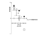
- FIG. 7 is a graph schematically showing the relationship between the operating state of the solenoid units 10a and 10b and the magnetic flux density detected by the magnetic sensor 23.
- the magnetic flux density detected by the magnetic sensor 23 in the configuration of FIG. For comparison, the magnetic flux density detected by the magnetic sensor 23 in the configuration of FIG.
- both solenoid parts 10a and 10b are in the OFF state
- both plungers 11a and 11b move upward in the Y-axis direction under the urging force of springs 12a and 12b.
- the sensor magnets 21a and 21b are in the vicinity of the sensor core 22-3 on the upper side in the Y-axis direction, and magnetic flux flows to the sensor core 22-2 on which the magnetic sensor 23 is installed in the left direction of the paper, thereby strengthening the magnetic flux. Therefore, the magnetic flux density detected by the magnetic sensor 23 is a positive value.
- both solenoid parts 10a and 10b when both solenoid parts 10a and 10b are in the ON state, both plungers 11a and 11b move downward in the Y-axis direction under the electromagnetic force of the stator. At this time, the sensor magnets 21a and 21b are located in the vicinity of the sensor core 22-1 on the lower side in the Y-axis direction. Therefore, the magnetic flux density detected by the magnetic sensor 23 is a negative value.
- the direction of the magnetic flux flowing through the magnetic sensor 23 can be reversed between when the solenoid parts 10a and 10b are in the ON state and when the solenoid parts 10a and 10b are in the OFF state.
- the change in magnetic flux density according to the positions of the plungers 11a and 11b can be increased. Therefore, even if the magnetic flux when the coil is energized flows to the sensor core 22-2, the influence of the magnetic flux when the coil is energized can be reduced.
- the graph of FIG. 7 when the magnetic flux density flowing through the sensor core 22-2 is affected by the magnetic flux when the coil is energized, fluctuations in the magnetic flux density in the range indicated by the arrow A can occur. Even if it is affected, there is a difference in magnetic flux density indicated by the arrow B between (OFF / OFF) and (OFF / ON), so that resistance to magnetic flux when the coil is energized is improved.
- the sensor magnets 21a and 21b having the same magnetic force have been described above, the sensor magnets 21a and 21b having different magnetic forces may be used.
- the sensor magnets 21a and 21b having different magnetic forces it is possible to determine which of the solenoid parts 10a and 10b is in the ON state.
- FIG. 8 when the sensor magnets 21 a and 21 b having different magnetic forces are used in the electromagnetic actuator 1 according to the third embodiment, the operation state of the two sets of solenoid parts 10 a and 10 b and the magnetic flux detected by the magnetic sensor 23.
- the graph which represented the relationship with a density typically is shown.
- the position of the plungers 11a and 11b is detected by detecting which of the coils 14a and 14b is energized. Can also be determined.
- the sensor core 22-1 shown in FIG. 6 may be used as a part of the yoke 5 embedded in the case 4 of the electromagnetic actuator 1.
- the sensor core 22-1 becomes a shortcut magnetic circuit through which the magnetic flux generated in the cores 13a and 13b flows when the coil is energized.
- the sensor core 22-2 and the magnetic sensor 23 are outside the shortcut magnetic circuit, it is possible to reduce the influence of the magnetic flux when the coil is energized.
- the sensor core 22-3 shown in FIG. 6 may be used as a part of the yoke 5. In this case, both end portions of the sensor core 22-3 shown in FIG.
- FIG. 9 is a front view showing a configuration example of the position detection unit 20 of the electromagnetic actuator 1 according to Embodiment 4 of the present invention. 9 of the electromagnetic actuator 1 according to Embodiment 4 has the same configuration as that of the electromagnetic actuator 1 shown in FIG.
- the position detector 20 of the fourth embodiment has two sensor cores 22-1 and 22-2 arranged in parallel to each other on the XY plane parallel to the moving direction of the plungers 11a and 11b.
- the sensor core 22-1 is disposed at a position facing the sensor magnets 21a and 21b fixed to the plungers 11a and 11b.
- the sensor core 22-1 becomes a shortcut magnetic circuit through which the magnetic flux generated in the cores 13a and 13b flows when the coil is energized.
- the sensor core 22-2 is disposed on the upper side of the sensor core 22-1. Both end portions of the sensor core 22-2 are bent downward, and their tips are magnetically connected to the coils 14a and 14b. Therefore, the sensor core 22-2 becomes a shortcut magnetic circuit through which the magnetic flux generated in the cores 13a and 13b flows when the coil is energized.
- the sensor core 22-2 is formed with a convex portion 24 that protrudes downward, and a magnetic sensor 23 is provided.
- the convex portion 24 provides a path through which the magnetic fluxes of the sensor magnets 21a and 21b can flow in common.
- the portion where the magnetic sensor 23 is installed is an air gap between the convex portion 24 and the sensor core 22-1 and has a large magnetic resistance. Therefore, the magnetic flux generated when the coil is energized mainly differs from the sensor core 22-1 without the air gap. It flows to each of the sensor cores 22-2.
- This magnetic flux is indicated by a one-dot chain line arrow in FIG.
- the air gap portion 14c between the coil 14a and the coil 14b the magnetic resistance is increased, and the magnetic flux of the sensor magnets 21a and 21b passes from the lower sensor core 22-1 through the convex portion 24 to the upper sensor core. It flows to 22-2.
- This magnetic flux is indicated by solid arrows in FIGS. 9 (a), 9 (b) and 9 (c). The difference in the thickness of the solid line of the arrow indicates the difference in the magnetic flux density.
- a convex portion 24 is provided on the upper sensor core 22-2, and the magnetic sensor 23 is disposed in an air gap portion where the convex portion 24 and the lower sensor core 22-1 face each other.
- the magnetic sensor 23 may be arranged by providing a convex portion on the lower sensor core 22-1.
- one of the solenoid parts 10a and 10b is in the ON state and the other is in the OFF state, and one of the plungers 11a and 11b is on the lower side in the Y-axis direction, and the other is the Y-axis.
- the magnetic resistance has an intermediate value
- the density of the magnetic flux passing through the magnetic sensor 23 also has an intermediate value.
- the position of the plungers 11a and 11b can be detected by the magnetic sensor 23 detecting a change in the magnetic flux density flowing through the convex portion 24. Also, in the fourth embodiment, similarly to the first embodiment, when only one of the solenoid parts 10a and 10b is in the ON state, it is detected by detecting which of the coils 14a and 14b is energized. It is possible to determine the positions of the plungers 11a and 11b.
- FIG. 10A and 10B show a configuration example of an electromagnetic actuator 1 according to Embodiment 5 of the present invention.
- FIG. 10A is a plan view and FIG. 10B is a cross-sectional view.
- the case 3 is removed and the shield member 25 is exposed.
- 10, parts that are the same as or correspond to those in FIG. 1 are given the same reference numerals, and descriptions thereof are omitted.
- the electromagnetic actuator 1 has a configuration in which a shield member 25 that shields the magnetic flux flowing from the cores 13a and 13b to the magnetic sensor 23 is added to the electromagnetic actuator 1 of the first embodiment shown in FIG. is there.
- the shield member 25 shields the magnetic circuit of the position detection unit 20 using the sensor magnets 21a and 21b as a magnetomotive force source by connecting the magnetic circuit of the solenoid units 10a and 10b to flow a magnetic flux when the coil is energized. is there. Thereby, the magnetic flux at the time of coil energization does not flow into sensor core 22 which installed magnetic sensor 23, but it can reduce the influence of magnetic fluxes other than sensor magnets 21a and 21b.
- the shape of the shield member 25 shown in FIG. 10 is an example, and any shape that can shield magnetic fluxes other than the sensor magnets 21a and 21b, such as a magnetic flux generated when the coil is energized, may be used. Similarly, a shield member may be provided in the electromagnetic actuator 1 according to the second to fourth embodiments.
- the sensor magnet 22a, 21b can also be made to have a smaller area, that is, a magnetic path cross-sectional area, than the area of the opposed surfaces of the sensor magnets 21a, 21b opposed to the sensor core 22 by the sensor magnet 22a.
- the influence of magnetic fluxes other than 21a and 21b can be reduced.
- the positional relationship between the cores 13a and 13b constituting the magnetic circuit of the solenoid units 10a and 10b and the sensor core 22 is the configuration example of FIG. 1, the area of the facing surface of the sensor core 22 facing the sensor magnets 21a and 21b.
- the air gap between the cores 13a and 13b is narrowed, the magnetic resistance is reduced, and the magnetic flux leaking to the sensor core 22 is increased when the coil is energized.
- the area of the opposing surface of the sensor core 22 facing the sensor magnets 21a and 21b is reduced, the influence of the leakage magnetic flux when the coil is energized can be reduced.
- the cross-sectional area of the magnetic path constituting the magnetic circuit of the position detection unit 20 is larger, the magnetic resistance of the magnetic path is reduced, the magnetic flux density passing through the magnetic sensor 23 is increased, and is not easily affected by the outside. Become.
- FIG. 11 shows a configuration example of the position detection unit 20 of the electromagnetic actuator 1 according to the fifth embodiment.
- the taper part 26 of the shape which tapers as the sensor magnet 21a is approached is formed in the opposing surface of the sensor core 22 which opposes the sensor magnet 21a.
- a similar tapered portion 26 is formed on the surface of the sensor core 22 facing the sensor magnet 21b.
- the shape of the facing surface of the sensor core 22 facing the sensor magnets 21a and 21b shown in FIG. 11 is an example, and the area of the facing surface of the sensor core 22 is smaller than the area of the facing surfaces of the sensor magnets 21a and 21b. I just need it.
- the tapered portion 26 may be formed in the sensor core.
- the front view of FIG. 12 shows an example in which the tapered portion 26 is formed on the sensor core 22 of the second embodiment.
- the electromagnetic actuator 1 has two sets of solenoid portions 10a and 10b, the position of the two plungers 11a and 11b is detected by one magnetic sensor 23.
- the above-mentioned solenoid part may be provided, and a configuration in which the position of three or more plungers is detected by one magnetic sensor may be used.
- three plungers are arranged at three vertices of a triangle, three sensor magnets are arranged corresponding to each of the three plungers, and three are arranged on three sides of the triangle.
- One sensor core is arranged, and the magnetic flux flowing through the three sensor cores changing according to the positions of the three plungers is detected by one magnetic sensor.
- two magnetic sensors may be arranged in an electromagnetic actuator having three sets of solenoid parts. In other words, the operation of the solenoid unit can be detected by using fewer magnetic sensors than the number of solenoid units.
- the present invention can freely combine each embodiment, modify any component of each embodiment, or omit any component of each embodiment. It is.
- the electromagnetic actuator according to the present invention detects the positions of the plurality of plungers, in the internal combustion engine, an electromagnetic that switches between the high cam and the low cam of the camshaft to adjust the lift amount of the intake or exhaust valve. Suitable for use in actuators.
- Electromagnetic actuator 2-4 case, 5 yoke, 6 connector, 10a, 10b solenoid part, 11a, 11b plunger, 12a, 12b spring, 13a, 13b core, 14a, 14b coil, 14c air gap part, 15a, 15b boss , 16a, 16b pin, 17a, 17b link, 18a, 18b shaft, 20 position detector, 21a, 21b sensor magnet, 22, 22-1, 22-2, 22-3 sensor core, 22a, 22b air gap, 22A , 22B split core, 23 magnetic sensor, 24 convex part, 25 shield member, 26 taper part.
Landscapes
- Physics & Mathematics (AREA)
- General Physics & Mathematics (AREA)
- Engineering & Computer Science (AREA)
- Electromagnetism (AREA)
- Power Engineering (AREA)
- Mechanical Engineering (AREA)
- General Engineering & Computer Science (AREA)
- Electromagnets (AREA)
- Measurement Of Length, Angles, Or The Like Using Electric Or Magnetic Means (AREA)
- Valve Device For Special Equipments (AREA)
Abstract
Priority Applications (3)
| Application Number | Priority Date | Filing Date | Title |
|---|---|---|---|
| JP2017521458A JP6498287B2 (ja) | 2015-06-04 | 2015-06-04 | 電磁アクチュエータ |
| US15/579,096 US10365124B2 (en) | 2015-06-04 | 2015-06-04 | Electromagnetic actuator |
| PCT/JP2015/066233 WO2016194207A1 (fr) | 2015-06-04 | 2015-06-04 | Actionneur électromagnétique |
Applications Claiming Priority (1)
| Application Number | Priority Date | Filing Date | Title |
|---|---|---|---|
| PCT/JP2015/066233 WO2016194207A1 (fr) | 2015-06-04 | 2015-06-04 | Actionneur électromagnétique |
Publications (1)
| Publication Number | Publication Date |
|---|---|
| WO2016194207A1 true WO2016194207A1 (fr) | 2016-12-08 |
Family
ID=57440821
Family Applications (1)
| Application Number | Title | Priority Date | Filing Date |
|---|---|---|---|
| PCT/JP2015/066233 Ceased WO2016194207A1 (fr) | 2015-06-04 | 2015-06-04 | Actionneur électromagnétique |
Country Status (3)
| Country | Link |
|---|---|
| US (1) | US10365124B2 (fr) |
| JP (1) | JP6498287B2 (fr) |
| WO (1) | WO2016194207A1 (fr) |
Cited By (1)
| Publication number | Priority date | Publication date | Assignee | Title |
|---|---|---|---|---|
| JPWO2018011883A1 (ja) * | 2016-07-12 | 2018-09-27 | 三菱電機株式会社 | 電磁アクチュエータ |
Families Citing this family (4)
| Publication number | Priority date | Publication date | Assignee | Title |
|---|---|---|---|---|
| JP2018196255A (ja) * | 2017-05-18 | 2018-12-06 | アルパイン株式会社 | 振動発生装置および振動機構付き入力装置 |
| DE102017121947A1 (de) * | 2017-09-21 | 2019-03-21 | Kendrion (Villingen) Gmbh | Stellvorrichtung mit einem abgedichteten Führungszylinder |
| KR102781924B1 (ko) | 2019-10-16 | 2025-03-18 | 삼성전자주식회사 | 카메라를 포함하는 전자 장치 |
| US11640864B2 (en) * | 2019-12-05 | 2023-05-02 | Deltrol Corp. | System and method for detecting position of a solenoid plunger |
Citations (5)
| Publication number | Priority date | Publication date | Assignee | Title |
|---|---|---|---|---|
| JP2001155921A (ja) * | 1999-11-26 | 2001-06-08 | Toyota Motor Corp | 電磁式弁駆動装置 |
| JP2003336509A (ja) * | 2002-05-17 | 2003-11-28 | Toyota Motor Corp | 電磁駆動弁 |
| US20120031360A1 (en) * | 2009-04-16 | 2012-02-09 | Daimler Ag | Electromagnetic camshaft-adjuster device |
| JP2013239538A (ja) * | 2012-05-14 | 2013-11-28 | Denso Corp | 電磁アクチュエータ |
| JP2014020260A (ja) * | 2012-07-17 | 2014-02-03 | Denso Corp | 電磁アクチュエータ |
Family Cites Families (5)
| Publication number | Priority date | Publication date | Assignee | Title |
|---|---|---|---|---|
| US5032812A (en) | 1990-03-01 | 1991-07-16 | Automatic Switch Company | Solenoid actuator having a magnetic flux sensor |
| ES2205648T3 (es) * | 1998-07-07 | 2004-05-01 | Daimlerchrysler Ag | Apantallamiento magnetico de un elemento actuador para el control electromagnetico de valvulas. |
| DE102009049009B4 (de) * | 2009-10-09 | 2012-10-04 | Pierburg Gmbh | Aktuator für eine Verbrennungskraftmaschine |
| JP6107621B2 (ja) * | 2013-11-29 | 2017-04-05 | スズキ株式会社 | 自動二輪車のシフトロッド装置 |
| JP6248871B2 (ja) * | 2014-09-05 | 2017-12-20 | 株式会社デンソー | 電磁アクチュエータ |
-
2015
- 2015-06-04 WO PCT/JP2015/066233 patent/WO2016194207A1/fr not_active Ceased
- 2015-06-04 JP JP2017521458A patent/JP6498287B2/ja not_active Expired - Fee Related
- 2015-06-04 US US15/579,096 patent/US10365124B2/en not_active Expired - Fee Related
Patent Citations (5)
| Publication number | Priority date | Publication date | Assignee | Title |
|---|---|---|---|---|
| JP2001155921A (ja) * | 1999-11-26 | 2001-06-08 | Toyota Motor Corp | 電磁式弁駆動装置 |
| JP2003336509A (ja) * | 2002-05-17 | 2003-11-28 | Toyota Motor Corp | 電磁駆動弁 |
| US20120031360A1 (en) * | 2009-04-16 | 2012-02-09 | Daimler Ag | Electromagnetic camshaft-adjuster device |
| JP2013239538A (ja) * | 2012-05-14 | 2013-11-28 | Denso Corp | 電磁アクチュエータ |
| JP2014020260A (ja) * | 2012-07-17 | 2014-02-03 | Denso Corp | 電磁アクチュエータ |
Cited By (2)
| Publication number | Priority date | Publication date | Assignee | Title |
|---|---|---|---|---|
| JPWO2018011883A1 (ja) * | 2016-07-12 | 2018-09-27 | 三菱電機株式会社 | 電磁アクチュエータ |
| US10804019B2 (en) | 2016-07-12 | 2020-10-13 | Mitsubishi Electric Corporation | Electromagnetic actuator |
Also Published As
| Publication number | Publication date |
|---|---|
| US20180172478A1 (en) | 2018-06-21 |
| US10365124B2 (en) | 2019-07-30 |
| JP6498287B2 (ja) | 2019-04-10 |
| JPWO2016194207A1 (ja) | 2017-10-19 |
Similar Documents
| Publication | Publication Date | Title |
|---|---|---|
| JP6498287B2 (ja) | 電磁アクチュエータ | |
| EP2472539B1 (fr) | Relais électromagnétique | |
| CN102947915B (zh) | 电磁继电器 | |
| CN103109331B (zh) | 电磁调节设备 | |
| CN107337046B (zh) | 电梯的机械制动器及监控该制动器的操作状态的方法 | |
| US11162515B2 (en) | Servo valve | |
| JP4545406B2 (ja) | 位置検出装置 | |
| KR102111221B1 (ko) | 연료 분사기, 이동식 전기자의 위치를 확인하기 위한 방법 및 모터 제어 | |
| US10804019B2 (en) | Electromagnetic actuator | |
| US20150229239A1 (en) | Inertial drive actuator | |
| WO2019021531A1 (fr) | Actionneur électromagnétique et mécanisme de réglage hydraulique | |
| CN112400209A (zh) | 具有真空断续器和驱动装置的中压断路器以及用于操作中压断路器的方法 | |
| WO2017069101A1 (fr) | Mécanisme de soupape variable | |
| JP6334228B2 (ja) | 磁性体検知器 | |
| CN104137411B (zh) | 惯性驱动致动器 | |
| JP2010185854A (ja) | 位置検出センサ及び位置検出装置 | |
| RU2331130C1 (ru) | Электромагнит с поляризующей обмоткой | |
| CN203879931U (zh) | 磁力轴承 | |
| JP2002228405A (ja) | 変位検出装置 | |
| CN120457514A (zh) | 电磁继电器 | |
| JP2023167540A (ja) | ソレノイド | |
| WO2025154395A1 (fr) | Relais électromagnétique | |
| WO2016125303A1 (fr) | Actionneur | |
| CN116110746A (zh) | 一种接触器 | |
| JP2018184926A (ja) | 燃料噴射装置 |
Legal Events
| Date | Code | Title | Description |
|---|---|---|---|
| 121 | Ep: the epo has been informed by wipo that ep was designated in this application |
Ref document number: 15894240 Country of ref document: EP Kind code of ref document: A1 |
|
| ENP | Entry into the national phase |
Ref document number: 2017521458 Country of ref document: JP Kind code of ref document: A |
|
| WWE | Wipo information: entry into national phase |
Ref document number: 15579096 Country of ref document: US |
|
| NENP | Non-entry into the national phase |
Ref country code: DE |
|
| 122 | Ep: pct application non-entry in european phase |
Ref document number: 15894240 Country of ref document: EP Kind code of ref document: A1 |