WO2016194399A1 - 電力変換装置 - Google Patents
電力変換装置 Download PDFInfo
- Publication number
- WO2016194399A1 WO2016194399A1 PCT/JP2016/052855 JP2016052855W WO2016194399A1 WO 2016194399 A1 WO2016194399 A1 WO 2016194399A1 JP 2016052855 W JP2016052855 W JP 2016052855W WO 2016194399 A1 WO2016194399 A1 WO 2016194399A1
- Authority
- WO
- WIPO (PCT)
- Prior art keywords
- circuit
- current
- short
- conversion device
- power conversion
- Prior art date
- Legal status (The legal status is an assumption and is not a legal conclusion. Google has not performed a legal analysis and makes no representation as to the accuracy of the status listed.)
- Ceased
Links
Images


Classifications
-
- H—ELECTRICITY
- H02—GENERATION; CONVERSION OR DISTRIBUTION OF ELECTRIC POWER
- H02P—CONTROL OR REGULATION OF ELECTRIC MOTORS, ELECTRIC GENERATORS OR DYNAMO-ELECTRIC CONVERTERS; CONTROLLING TRANSFORMERS, REACTORS OR CHOKE COILS
- H02P27/00—Arrangements or methods for the control of AC motors characterised by the kind of supply voltage
- H02P27/04—Arrangements or methods for the control of AC motors characterised by the kind of supply voltage using variable-frequency supply voltage, e.g. inverter or converter supply voltage
- H02P27/06—Arrangements or methods for the control of AC motors characterised by the kind of supply voltage using variable-frequency supply voltage, e.g. inverter or converter supply voltage using DC to AC converters or inverters
-
- G—PHYSICS
- G01—MEASURING; TESTING
- G01R—MEASURING ELECTRIC VARIABLES; MEASURING MAGNETIC VARIABLES
- G01R31/00—Arrangements for testing electric properties; Arrangements for locating electric faults; Arrangements for electrical testing characterised by what is being tested not provided for elsewhere
- G01R31/34—Testing dynamo-electric machines
- G01R31/343—Testing dynamo-electric machines in operation
-
- G—PHYSICS
- G01—MEASURING; TESTING
- G01R—MEASURING ELECTRIC VARIABLES; MEASURING MAGNETIC VARIABLES
- G01R31/00—Arrangements for testing electric properties; Arrangements for locating electric faults; Arrangements for electrical testing characterised by what is being tested not provided for elsewhere
- G01R31/50—Testing of electric apparatus, lines, cables or components for short-circuits, continuity, leakage current or incorrect line connections
- G01R31/52—Testing for short-circuits, leakage current or ground faults
-
- H—ELECTRICITY
- H02—GENERATION; CONVERSION OR DISTRIBUTION OF ELECTRIC POWER
- H02H—EMERGENCY PROTECTIVE CIRCUIT ARRANGEMENTS
- H02H7/00—Emergency protective circuit arrangements specially adapted for specific types of electric machines or apparatus or for sectionalised protection of cable or line systems, and effecting automatic switching in the event of an undesired change from normal working conditions
- H02H7/10—Emergency protective circuit arrangements specially adapted for specific types of electric machines or apparatus or for sectionalised protection of cable or line systems, and effecting automatic switching in the event of an undesired change from normal working conditions for converters; for rectifiers
- H02H7/12—Emergency protective circuit arrangements specially adapted for specific types of electric machines or apparatus or for sectionalised protection of cable or line systems, and effecting automatic switching in the event of an undesired change from normal working conditions for converters; for rectifiers for static converters or rectifiers
- H02H7/122—Emergency protective circuit arrangements specially adapted for specific types of electric machines or apparatus or for sectionalised protection of cable or line systems, and effecting automatic switching in the event of an undesired change from normal working conditions for converters; for rectifiers for static converters or rectifiers for inverters, i.e. DC/AC converters
- H02H7/1227—Emergency protective circuit arrangements specially adapted for specific types of electric machines or apparatus or for sectionalised protection of cable or line systems, and effecting automatic switching in the event of an undesired change from normal working conditions for converters; for rectifiers for static converters or rectifiers for inverters, i.e. DC/AC converters responsive to abnormalities in the output circuit, e.g. short circuit
-
- H—ELECTRICITY
- H02—GENERATION; CONVERSION OR DISTRIBUTION OF ELECTRIC POWER
- H02P—CONTROL OR REGULATION OF ELECTRIC MOTORS, ELECTRIC GENERATORS OR DYNAMO-ELECTRIC CONVERTERS; CONTROLLING TRANSFORMERS, REACTORS OR CHOKE COILS
- H02P29/00—Arrangements for regulating or controlling electric motors, appropriate for both AC and DC motors
- H02P29/02—Providing protection against overload without automatic interruption of supply
- H02P29/024—Detecting a fault condition, e.g. short circuit, locked rotor, open circuit or loss of load
- H02P29/027—Detecting a fault condition, e.g. short circuit, locked rotor, open circuit or loss of load the fault being an over-current
-
- H—ELECTRICITY
- H02—GENERATION; CONVERSION OR DISTRIBUTION OF ELECTRIC POWER
- H02P—CONTROL OR REGULATION OF ELECTRIC MOTORS, ELECTRIC GENERATORS OR DYNAMO-ELECTRIC CONVERTERS; CONTROLLING TRANSFORMERS, REACTORS OR CHOKE COILS
- H02P29/00—Arrangements for regulating or controlling electric motors, appropriate for both AC and DC motors
- H02P29/02—Providing protection against overload without automatic interruption of supply
- H02P29/032—Preventing damage to the motor, e.g. setting individual current limits for different drive conditions
Definitions
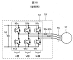
- the present invention relates to a power conversion device and a control method.
- FIG. 15 shows a conventional power converter, a motor, and a cable connecting them.
- the power conversion device 91 includes an inverter circuit 92 that converts a direct current for driving the motor into an alternating current, current sensors 93a and 93b, and a smoothing capacitor 94.
- the inverter circuit 92 includes switching elements 95a to 95f formed of a semiconductor, and two switching elements are paired to form a three-phase bridge of U, V, and W. The switching elements for one phase are switched on alternately so as not to be turned on simultaneously.
- the outputs U, V, W of each phase are connected to a motor 97 using three cables 96, and supply AC power to the motor.
- the current sensor 93a or 93b in the power converter detects an overcurrent.
- the conversion operation is stopped by turning off all the switching elements, and the switching elements are prevented from being destroyed by thermal energy generated by a large current.
- Patent Document 1 JP-A-10-23795.
- This publication states that “when the slope of the detected current waveform is“ 0 ”or smaller than the reference, it can be diagnosed that there is an abnormality in the current detection circuit, the switching element, and the motor winding, and the switching element to be turned on can be changed. Similarly, the slope of the waveform of the current detection circuit is obtained to identify an abnormal location. If the detected current waveform has a slope that is much larger than the reference, it can be diagnosed that a short circuit has occurred in the cable or the motor winding. Is described.
- Patent Document 1 introduces a method of estimating an abnormality by turning on two switching elements for a short time after a short circuit occurs and observing the current gradient.
- the slope of the current is determined by the inductance L of the short circuit path, the short circuit location can be estimated based on the inductance L.
- an object of the present invention is to provide a power conversion device that determines a short-circuit portion in a motor and on a cable and notifies a user or an external device or system of the determination result.
- a power conversion device of the present invention is a power conversion device that includes a plurality of switching elements and drives a motor connected by a cable by their on / off control, and controls the current of the motor.
- An inverter circuit composed of a plurality of switching elements for the upper arm and a plurality of switching elements for the lower arm, and an information output means for notifying the outside of the apparatus inside, and generated by the motor and the cable.
- the power conversion device of the present invention generates a short-circuit current by simultaneously turning on specific switching elements for a short-circuit accident between phases generated by the motor and the cable, and the current increase speed at the time of the short-circuit and the current after the short-circuit Based on the decreasing speed, it is possible to identify and determine the short-circuit location. Furthermore, the short-circuit location determination result can be displayed on the display or transmitted wirelessly to the user, external device, or external system. There is an effect that it can be notified.
- FIG. 6 It is a figure showing the relationship between the state of the switching element of U and W phase, and a short circuit current path at the time of U-W phase short circuit occurrence. Simulation result of current waveform when switching element operates as shown in Fig. 6 when short circuit occurs It is the figure which showed the flowchart of the subroutine process which the short circuit location determination S32 calls. It is a block diagram of the indicators 6 and 56. FIG. It is a manual explaining the numbers displayed on the display devices 6 and 56. It is a block diagram of the transmitters 7 and 57. FIG. It is a block diagram of the 2nd Example of the power converter device of this invention. It is a block diagram of a voltage rise detection circuit.
- FIG. 1 shows a configuration diagram of a first embodiment of the power converter of the present invention.
- the power converter 1 includes a forward converter circuit 2, a smoothing capacitor 3, and an inverse converter circuit 4 for inputting AC power and supplying power to the motor.
- the power converter 1 also includes a control circuit 5 for controlling the inverse converter circuit 4, a display 6 for displaying output information of the control circuit, and a transmitter 7 for wirelessly transmitting the output information of the control circuit.
- the relay output 14 for outputting as an abnormal signal is disclosed, but the present invention is not limited to the relay.
- the forward converter circuit 2 converts AC power input from the R, S, and T terminals into DC power.
- the smoothing capacitor 3 is provided in the DC voltage wiring shown as N and P nodes.
- the inverse converter circuit 4 converts DC power into AC power for driving the motor.
- the inverse converter circuit 4 is composed of a semiconductor element composed of a switching element and a diode connected in antiparallel to the switching element. In FIG. 1, an IGBT is used as a switching element, but it may be constituted by a MOSFET.
- the inverse converter circuit 4 has six switching elements Ua, Ub, Va, Vb, Wa, Wb.
- Ua, Va, and Wa are referred to as an upper arm
- Ub, Vb, and Wb are referred to as a lower arm.
- the switching element of the upper arm and the lower arm for example, Ua and Ub are alternately turned on to control the current output from the output terminal U.
- a three-phase motor 10 is connected to output terminals U, V, and W of the power conversion device 1 via a cable 9, and the motor is driven by currents output from the output terminals U, V, and W.
- the phase to be omitted may be U or V instead of W.
- the current sensor 13 is also provided in the wiring connected to the DC-side node N of the inverse converter circuit 4. Arranging the current sensor 13 at the position shown in the figure is suitable for quickly detecting overcurrent detection or the like because any current flowing from any of the output terminals U, V, and W to the node N can be observed. Yes.
- the power converter 1 includes a forward converter circuit 2 for inputting AC power. However, when DC power is input, the forward converter circuit 2 is omitted and the DC power is supplied to the nodes P and N. You may enter directly into.
- the control circuit 5 includes a control unit 21 that controls the control circuit 5 using a built-in program incorporated in advance, and a driver circuit 22 that drives the six transistors of the inverse converter circuit 4. In normal motor driving, the control unit 21 feeds back the current values measured by the current sensors 11 and 12 while the driver circuit 22 causes the inverse converter circuit 4 to perform PWM control.
- the control circuit 5 includes a comparator 23 that outputs a trigger signal OC when the current threshold value ith0 is exceeded, and a comparator 24 that outputs a trigger signal DT when the current threshold value ith1 is exceeded.
- the current measurement circuits 26 and 27 that sample the measurement values of the timer 25 and the current sensors 11 and 12 that start the operation in response to the trigger signal DT of the comparator 24 and digitize the absolute value of the current amount, and the current measurement circuits 26 and 27.
- the selection circuit 28 for selecting the larger one of the values of the value and the determination unit 29 for determining the short-circuit position are provided.
- elements that can be configured with only a logic circuit such as the control unit 21, timer 25, selection circuit 28, and determination unit 29 in the control circuit 5 may be realized by software using a microcomputer or programmable logic. Is possible.
- the comparators 23 and 24 since the comparators 23 and 24 have the same function, they may be constituted by one comparator by a time sharing operation.
- the comparator 23 transmits a trigger signal OC to the control unit 21 when the current value iN measured by the current sensor 13 exceeds the threshold value ith0.
- the threshold value isth0 is set to be several times the maximum current value during normal operation, thereby preventing malfunction due to noise.
- the control unit 21 causes the driver circuit 22 to turn off the switching elements Ub, Vb, Wb to suppress an increase in the short circuit current, and then turn off the switching elements Ua, Va, Wa to stop the short circuit current.
- the threshold value isth1 supplied to the comparator 24 is a threshold value used for determination of a short-circuited phase, which will be described later. From the viewpoint of device protection, it is desirable that the threshold value isth1 is equal to or less than the threshold value isth0 and that the current value is large enough to determine the short-circuited phase.
- FIG. 2 shows operation waveforms after the occurrence of a short circuit in the first embodiment of the power converter of the present invention.
- the vertical axis represents the ON / OFF state of the switching elements Ua, Va, Wa, Ub, Vb, Wb, the absolute value
- the horizontal axis indicates time.
- FIG. 2 shows an example in which a short circuit occurs between W and U at time ts1. When a short circuit occurs at time ts1, the current measurement value iN of the current sensor 13 increases rapidly.
- the control unit 21 detects a short circuit.
- the control unit 21 turns off Ub, Vb, and Wb, the increase in short-circuit current stops, and when Ua, Va, and Wa are turned off at time ts3, the short-circuit current stops soon.
- the current iU is a negative current (direction flowing into the inverse converter circuit).
- FIG. 3 is a flowchart showing the operation of the control circuit 5 for determining the short-circuit position. The flowchart of FIG. 3 is started after the control circuit 5 detects a short circuit, but may be started by an external instruction from the input unit 8 of FIG.
- the control circuit 5 stands by until the current flowing through the motor or the like attenuates and disappears (S01, S02). After the current becomes 0, the switching elements Ua and Vb are turned on to start the operation of the timer 25 (S03, S04, time t1 in FIG. 2). The control circuit 5 then waits for a certain time, and waits for the trigger signal DT from the comparator 24 during that time (S05, S06). If there is a short circuit between U and V, the current increases in a short time, so the control circuit 5 detects the trigger signal DT within the time and there is a short circuit between U and V. Is substituted into the variable B (S07). If the trigger signal DT is not received within a predetermined time, the control circuit 5 determines that there is no short circuit between U and V, and turns off the switching elements Ua and Vb to reset the counter 25 (S08, S09, time t2 in FIG.
- the control circuit 5 turns on the switching elements Va and Wb and starts the operation of the timer 25 (S10, S11, time t3 in FIG. 2). After that, it waits for a certain time, and waits for the trigger signal DT from the comparator 24 during that time (S12, S13). If there is a short circuit between V and W, the current increases in a short time. Therefore, the control circuit 5 detects the trigger signal DT in time, and there is a short circuit between V and W. Is substituted into the variable B (S14). If the trigger signal DT is not received within a certain time, the control circuit 5 determines that there is no short circuit between V and W, turns off the switching elements Ua and Vb, and resets the counter 25 (S15, S16, time t4 in FIG.
- the control circuit 5 turns on the switching elements Wa and Ub and starts the operation of the timer 25 (S17, S18, time t5 in FIG. 2). After that, it waits for a certain time, and waits for the trigger signal DT from the comparator 24 during that time (S19, S20). If there is a short circuit between W and U, the current increases in a short time. Therefore, the control circuit 5 detects the trigger signal DT in time, and there is a short circuit between W and U. Is substituted for the variable B (S21).
- the control circuit 5 substitutes a numerical value 0 indicating that there is no short-circuit between any wires or the short-circuit phase is unknown in the variable B, and performs switching.
- the elements Wa and Ub are turned off (S22, S23).
- the control circuit 5 immediately turns off the lower-arm switching elements Ub, Vb, Wb, and sets the count value of the timer 25 at the same timing. It substitutes for variable tw1 (S24, S25, time t6 in FIG. 2). Further, the current measurement circuits 26 and 27 are caused to sample the current values iU and iV of the current sensors 11 and 12 at the same timing. Then, the selection circuit 28 outputs a large value among the absolute values of the sampled current values (in the case of FIG. 2, the absolute value
- control circuit 5 waits for a predetermined time tW2 (S27), causes the current measurement circuits 26 and 27 to sample again, and substitutes the output of the selection circuit 28 into the variable i2 (S28). Thereafter, when the switching elements Ua, Va, Wa of the upper arm are turned off, the current is quickly settled (S29, time t7 in FIG. 2).
- FIG. 4 is a diagram showing an example of a short-circuit portion generated on the cable and inside the motor.
- a to C represent examples of locations where a short circuit occurs.
- A is a short-circuit portion that occurs near the power converter on the cable
- B is a short-circuit portion that occurs near the motor on the cable
- C is a short-circuit portion that occurs inside the motor.
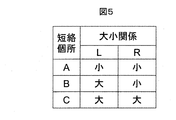
- FIG. 5 is a table showing the magnitude relationship between the inductance L and the resistance R of the short-circuit path for the short-circuit locations A to C shown in FIG.
- the short-circuit location is A
- L and R are the smallest.
- the short-circuit portion is B
- the reciprocal inductance Lcable of the cable is included in the path, so that the inductance L becomes relatively large.
- the short-circuit portion is C
- the winding resistance R_motor and the inductance L_motor of the motor internal wiring are included in the path, R and R are relatively large. Accordingly, the short-circuit locations A to C can be determined on the basis of the magnitude relationship between L and R.
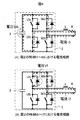
- FIG. 6 is a diagram showing the relationship between the state of the switching elements of the U and W phases and the short-circuit current path when a short circuit between the U and W phases occurs.
- an inductance L and a resistance R indicate the inductance and resistance of the short-circuit path.
- FIG. 6A shows a state in which the switching element Ub of the U-phase lower arm and the switching element Wa of the W-phase upper arm are ON, and shows the state from time t5 to t6 in FIG.
- the current i1 flowing through the short-circuit path increases at a current increase rate indicated by ⁇ i1 in the equation (1).
- Vdc the DC voltage of the smoothing capacitor
- L the inductance of the short circuit path
- R the resistance of the short circuit path.
- the resistance R in the short-circuit path is a resistance of a cable or a winding, so the value thereof is very small, and the exp ( ⁇ R ⁇ t / L) portion is almost equal to 1. Therefore, the current increase rate ⁇ i1 is expressed by Equation 2, and the current increase rate is determined by the inductance L.
- FIG. 6B shows a state in which the switching element Ub of the lower arm of the U phase is turned off after FIG. 6A, and shows a state from time t6 to t7 in FIG.
- the current i2 flows through the loop in which the free wheel diode and L and R are connected in series, and the current i2 decreases at the current decrease rate ⁇ i2 expressed by Equation 3. (Expression 3)
- ⁇ i2 ⁇ (i0 ⁇ R + Vf) / L ⁇ exp ( ⁇ R ⁇ t / L)
- i0 is the initial value of the current
- Vf is the forward voltage Vf of the freewheeling diode.
- Equation 5 Equation 5 is obtained.
- FIG. 7 shows a simulation result of the current waveform when the switching element operates as shown in FIG. 6 when a short circuit occurs.
- the DC voltage Vdc is 500 V
- the short-circuit path inductance L is 10 ⁇ H
- the short-circuit path resistance R is changed from 0 ⁇ to 1.0 ⁇ .
- the switching element is set in the state of FIG. 6A to increase the current flowing in the short-circuit path, and in period 2 thereafter, the switching element is set in the state of FIG. Reduced the current flowing through.
- the waveform of FIG. 7 shows that the current increase rate ⁇ i1 in period A is substantially constant without depending on the resistance R, and the current decrease rate in period B varies depending on the resistance R smaller than 1 ⁇ . This indicates that the resistance value of the short-circuit path can be estimated with high accuracy by obtaining the current decrease rate ⁇ i2.
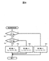
- FIG. 8 shows a flowchart of subroutine processing called by the short-circuit location determination S32 shown in the flowchart of FIG.
- a return value 3 that means that it is determined that L is small is returned (S55).
- a return value 2 which means that it is determined that L is large and R is small. Return (S54).
- the predetermined threshold values ⁇ and ⁇ are numerical values determined experimentally from the inductance value and resistance value of the cable and the motor, numerical values obtained by design using Formulas 2 and 4, or normal motor It is a numerical value obtained from an inductance value and a resistance value obtained by auto-tuning operation during driving.
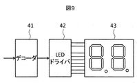
- Fig. 9 shows the configuration of the display 6.
- the display 6 includes a decoder 41, an LED driver 42, and a 2-digit LED segment 43.
- the values of the variables A and B sent from the control circuit 5 are decoded by the decoder 41 into a display pattern of numbers of LED segments, and the display pattern is converted into current by the LED driver 42.
- the LED driver 42 displays the value of the variable A in the first digit of the LED segment 43 and the value of the variable B in the second digit.
- FIG. 10 is a diagram showing a manual for explaining the numbers displayed on the display 6. If the numerical value displayed in the first digit is 1, it indicates that the short-circuit portion is inside the motor, 2 is on the cable near the motor, and 3 is on the cable near the inverter. If the numerical value displayed in the second digit is 1, it indicates that the short circuit phase is between U and V, 2 is between V and W, and 3 is between W and U. Note that 0 indicates unknown or no short circuit.
- the LED driver 42 constituting the display 6 shown in FIG. 9 may be a liquid crystal display driver, and the LED segment 43 may be a matrix display type liquid crystal display.
- the information to be displayed can be the corresponding short-circuit location shown in FIG.
- FIG. 11 shows a configuration diagram of the transmitter 7.
- the transmitter 7 includes a modulator 44, an amplifier 45, and an antenna 46.
- the values of variables A and B sent from the control circuit 5 are modulated by the modulator 44, power amplified by the amplifier 45, and externally transmitted from the antenna 46. Is transmitted wirelessly.
- another device or system can obtain the values of the variables A and B and obtain the information on the short circuit location by receiving and demodulating the wirelessly transmitted signal.
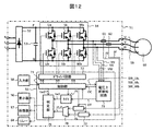
- FIG. 12 shows a configuration diagram of a second embodiment of the power converter of the present invention.
- the power conversion device 51 includes a forward converter circuit 52, a smoothing capacitor 53, and an inverse converter circuit 54 for inputting AC power and supplying power to the motor.
- the power conversion device 51 includes a control circuit 55 for controlling the reverse converter circuit 54, a display 56 for displaying output information of the control circuit, a relay output 64 for outputting as an abnormal signal, A transmitter 57 for wirelessly transmitting output information and an input unit 58 for inputting information to the control circuit are provided.
- the relay output 64 for outputting as an abnormal signal is disclosed, but it is not limited to the relay.
- the forward converter circuit 52 converts AC power input from the R, S, and T terminals into DC power.
- the smoothing capacitor 53 is provided in the DC voltage wiring shown as N and P nodes.
- the inverse converter circuit 54 converts DC power into AC power for driving the motor.
- the inverse converter circuit 54 is composed of a semiconductor element including a switching element and a diode connected in antiparallel to the switching element.
- the inverse converter circuit 54 has six switching elements Ua, Ub, Va, Vb, Wa, Wb.
- Ua, Va, and Wa are referred to as an upper arm
- Ub, Vb, and Wb are referred to as a lower arm.
- the switching element of the upper arm and the lower arm, for example, Ua and Ub are alternately turned on to control the current output from the output terminal U.
- a three-phase motor 60 is connected to the output terminals U, V, and W of the power conversion device 51 via a cable 59, and the motor is driven by the current output from the output terminals U, V, and W.
- the phase to be omitted may be U or V instead of W.
- the power converter 51 includes a forward converter circuit 52 for inputting AC power. However, when DC power is input, the forward converter circuit 52 is omitted and the DC power is supplied to the nodes P and N. You may enter directly into.
- the control circuit 55 includes a control unit 71 that controls the control circuit 55 by a built-in program incorporated in advance, and a driver circuit 72 that drives the six transistors of the inverse converter circuit 54.
- the controller 71 feeds back the current values measured by the current sensors 61 and 62 while the driver circuit 72 causes the inverse converter circuit 54 to perform PWM control.
- control circuit 55 is provided with a voltage increase detection circuit 73 for detecting an AC side output of the inverse converter 54, that is, a voltage increase of the output terminals U, V, W.
- a voltage increase detection circuit 73 for detecting an AC side output of the inverse converter 54, that is, a voltage increase of the output terminals U, V, W.
- Two voltage thresholds are set in the voltage rise detection circuit, and when the voltages VU, VV, VW of the output terminals U, V, W are exceeded, trigger signals OC and DT are output.
- the control circuit 55 also samples current measurement circuits 76 and 77 that sample the measurement values of the timer 75 and the current sensors 61 and 62 that start the operation in response to the trigger signal DT and digitize the absolute value of the current amount, and the current measurement circuit 76. , 77, a selection circuit 78 for selecting the larger one, and a determination unit 79 for determining a short-circuit position. Note that elements that can be configured by only a logic circuit, such as the control unit 71, the timers 73 and 24, the selection circuit 28, and the determination unit 29 in the control circuit 55, are realized by software using a microcomputer or programmable logic. It is also possible.
- FIG. 13 shows a configuration diagram of the voltage rise detection circuit.
- the voltage rise detection circuit 73 includes overvoltage protection circuits 81u, 81v, 81w, comparators 82u, 82v, 82w, 85u, 85v, 85w, AND gates 83u, 83v, 83w, for cutting a voltage outside the input rating of the comparator.
- Vth0 is a threshold value for short circuit protection
- Vth1 is a threshold value for short circuit phase determination.
- the comparator detects a voltage increase when the voltages VU, VV, and VW at the output terminals exceed the threshold value, and outputs a High signal. However, since the voltage at the output terminal rises even when the switching elements Ub, Vb, Wb of the lower arm of the inverter 54 are OFF, it is necessary to mask the voltage rise detection caused thereby.
- the AND gate is a signal sent from the control unit 71 for ON / OFF control of the switching elements Ub, Vb, Wb of the lower arm, and masks the output signal of the comparator.
- trigger signals OC and DT are output from the OR gates 84 and 87, respectively.
- the comparators 82u and 85u may be configured by one comparator by a time sharing operation. The same applies to the comparators 82v and 85v and the comparators 82w and 85w.
- the voltage rise detection circuit 73 transmits a trigger signal OC to the control unit 71 when the voltage rise exceeds the threshold value Vth0.
- the control unit 71 causes the driver circuit 72 to turn off the switching elements Ub, Vb, Wb to suppress an increase in the short circuit current, and then turn off the switching elements Ua, Va, Wa to stop the short circuit current.
- the threshold value Vth1 is a threshold value used for determination of a short-circuited phase, which will be described later. From the viewpoint of element protection, it is desirable that the threshold value Vth1 is equal to or less than the threshold value Vth0 and is a voltage value that is large enough to determine a short-circuited phase.
- FIG. 14 shows operation waveforms after occurrence of a short circuit in the second embodiment of the power conversion device of the present invention.
- the vertical axis indicates the ON / OFF state of the switching elements Ua, Va, Wa, Ub, Vb, Wb, the absolute value
- the horizontal axis indicates time.
- FIG. 14 shows an example in which a short circuit occurs between WU at time ts1. When a short circuit occurs at time ts1, the voltage VW at the output terminal W increases rapidly. When the threshold value Vth0 is exceeded at time ts2, the control unit 71 detects a short circuit.
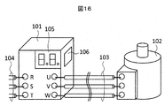
- FIG. 16 shows an example in which the above embodiment is applied as an industrial inverter.
- the power converter 101 and the driving motor 102 are connected by a cable 103.
- the power converter device 101 is supplied with electric power from the outside through the AC power supply wiring 104.
- the motor 102 is used to drive various industrial equipment such as an air conditioner, a compressor, a conveyor, and an elevator.
- FIG. 17 shows an example in which the above embodiment is applied to a railway vehicle.
- the power converters 112 and 113 of the present embodiment are installed under the floor of the railway vehicle 111.
- the carriages 114 and 115 of the railway vehicle 111 are provided with driving motors 116 and 117.
- the motor and the power converter are connected by cables 118 and 119.
- a short circuit occurs in the motors 116, 117 or on the cables 118, 119
- information on the short circuit location is displayed on the display provided in the power converters 112, 113, and short-circuited to an external system by wireless transmission. The location is notified.
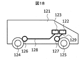
- FIG. 18 shows an example in which the above embodiment is applied to a motor vehicle.
- the power converters 122 and 123 of the present embodiment are installed inside the automobile 121.
- motors 126 and 127 for driving the wheels 124 and 125 are installed, and are connected to the power converter by cables 128 and 129.
- a short circuit occurs in the motors 126, 127 or on the cables 128, 129, information on the short circuit location is displayed on the display provided in the power converters 122, 123, and short circuit to an external system by wireless transmission. The location is notified.
- FIG. 19 shows an example in which the above embodiment is applied to an air conditioner.
- the air conditioner includes a main body part 132 attached to a building wall 131, a pipe 133 for reciprocating a refrigerant, and a compressor part 134.
- the main body 132 of the air conditioner is equipped with the power conversion device 135 of this embodiment.
- the compressor unit 134 is provided with a motor 136 for driving the compressor, and a cable 137 is connected between the motor and the power converter.
- a short circuit occurs in the motor 136 or on the cable 137, information on the short circuit location is displayed on the display provided in the power conversion device 135, and the short circuit location is notified to an external system by wireless transmission.
- DESCRIPTION OF SYMBOLS 1 Power converter device, 2 ... Forward converter circuit, 3 ... Smoothing capacitor, 4 ... Reverse converter circuit, 5 ... Control circuit, 6 ... Display, 7 ... Transmitter, 8 ... Input part, 9 ... Cable, DESCRIPTION OF SYMBOLS 10 ... Three-phase motor, 11-13 ... Current sensor, 14 ... Relay output, 21 ... Control part, 22 ... Driver circuit, 23, 24 ... Comparator, 25 ... Timer, 26, 27 ... Current measurement circuit, 28 ... Selection circuit , 29 ... determination unit, 41 ... decoder, 42 ... LED driver, 43 ... LED segment, 44 ... modulator, 45 ... amplifier, 51 ... power converter, 52 ...
- forward converter circuit 53 ... smoothing capacitor, 54 ... Inverter circuit, 55 ... control circuit, 56 ... display, 57 ... transmitter, 58 ... input unit, 59 ... cable, 60 ... three-phase motor, 61, 62 ... current sensor, 64 ... relay output, 71 ... control unit, 72 ... Dry Circuit, 73 ... Voltage rise detection circuit, 75 ... Timer, 76, 77 ... Current measurement circuit, 78 ... Selection circuit, 79 ... Determination unit, 81u-w ... Overvoltage protection circuit, 82u-w ... Comparator, 83u-w ... Logic Product gate, 84 ... logical sum gate, 85u-w ... comparator, 86u-w ...
Landscapes
- Engineering & Computer Science (AREA)
- Power Engineering (AREA)
- Physics & Mathematics (AREA)
- General Physics & Mathematics (AREA)
- Inverter Devices (AREA)
- Control Of Electric Motors In General (AREA)
- Control Of Ac Motors In General (AREA)
Abstract
短絡事故発生によって電力変換装置の動作が停止した場合、ケーブル上で短絡事故が発生したのかあるいはモータ内部で短絡事故が発生したのか、短絡が発生した場所を使用者が特定できない。 複数のスイッチング素子を具備してそれらのオンオフ制御によってケーブルで接続されたモータを駆動する電力変換装置であって、モータの電流を制御するための上アームの複数のスイッチング素子と下アームの複数のスイッチング素子から構成された逆変換器回路と、短絡個所を判定する判定部と、を具備し、判定部は、前記モータおよびケーブルで発生した相間の短絡個所を調査する際には、異なる相の上アーム、下アーム1つずつの前記スイッチング素子を同時にオンさせることで短絡電流を発生させ、短絡時の電流増加速度と、短絡後の電流減少速度に基づいて、短絡個所を判定する。
Description
本発明は、電力変換装置および制御方法に関する。
図15は、従来の電力変換装置と、モータおよびそれらを接続するケーブルを示している。電力変換装置91は、モータ駆動のための直流電流を交流電流に変換するインバータ回路92と電流センサ93a、93bと、平滑用コンデンサ94を備えている。インバータ回路92は、半導体で形成されたスイッチング素子95a~95fを備えており、2つのスイッチング素子が対になってU、V、Wの三相ブリッジを構成している。一相分のスイッチング素子は上下同時にONしないように交互にONさせてスイッチングを行う。各相の出力U、V、Wは3本のケーブル96を用いてモータ97と接続され、モータに交流電力を供給する。絶縁被覆の劣化や物理的損傷など、何らかの原因により、モータ97の内部やケーブル96で相間の短絡が起きた場合、電力変換装置内にある電流センサ93aあるいは93bが過電流を検知する。過電流を検知した場合は、全てのスイッチング素子をOFFにすることで変換動作を停止し、スイッチング素子が大電流により発生する熱エネルギなどで破壊されることを阻止する。
また、短絡発生個所の情報を知る方法として、特開平10-23795号公報(特許文献1)がある。本公報には「検出電流波形の傾きが「0」もしくは基準より小さい場合には、電流検出回路、スイッチング素子、モータの巻線に異常があるものと診断でき、オンにするスイッチング素子を変えて同様に電流検出回路の波形の傾きを求めて異常箇所を特定する。また、検出した電流波形の傾きが基準より非常に大きい場合には、ケーブルもしくはモータの巻線に短絡が生じているものとして診断できる。」と記載されている。
短絡によって電力変換装置の動作が停止した場合、その情報を使用者に報知することで短絡が発生したことを知らせることできる。しかしながら、短絡事故発生によって電力変換装置の動作が停止した場合、使用者はケーブル上で短絡事故が発生したのかあるいはモータ内部で短絡事故が発生したのか、短絡が発生した場所を特定することが課題であった。
短絡発生個所の情報を知る方法として、特許文献1に、短絡発生後に、2つのスイッチング素子を短時間ONにして、電流の傾きを見ることで異常を推定する方法が紹介されている。この場合、電流の傾きは短絡経路のインダクタンスLで決まるため、インダクタンスLに基づいた短絡個所の推定は可能である。しかしながら、インダクタンスLの情報のみでは、ケーブル上とモータ内での短絡の区別をすることが困難であった。
そこで、本発明の目的は、モータ内部およびケーブル上の短絡箇所を判定し、使用者や外部の装置やシステムに判定結果を報知する電力変換装置を提供することである。
上記目的を達成するため、本発明の電力変換装置は、複数のスイッチング素子を具備してそれらのオンオフ制御によってケーブルで接続されたモータを駆動する電力変換装置であって、モータの電流を制御するための上アームの複数のスイッチング素子と下アームの複数のスイッチング素子から構成されたインバータ回路と、装置内部の状況を外部に報知する情報出力手段を具備しており、前記モータおよび前記ケーブルで発生した相間の短絡個所を調査する際には、異なる相の上アーム、下アーム1つずつの前記スイッチング素子を同時にオンさせることで短絡電流を発生させ、短絡時の電流増加速度と、短絡後の電流減少速度に基づいて、短絡個所を判定するものである。
本発明の電力変換装置は、モータおよび前記ケーブルで発生した相間の短絡事故に対し、特定のスイッチング素子を同時にオンさせることで短絡電流を発生させ、短絡時の電流増加速度と、短絡後の電流減少速度に基づいて、短絡個所を特定判定することができ、さらには、短絡個所判定結果を表示器に表示する、あるいは、無線で送信することによって使用者、外部装置、外部システムへ短絡個所を報知することができるという効果がある。
以下では図面を用いて実施例について説明するが、以下に説明する各実施例は図示例に限定されるものではない。
図1に本発明の電力変換装置の第一の実施例の構成図を示す。電力変換装置1は、交流電力を入力してモータに電力を供給するための順変換器回路2、平滑用コンデンサ3、逆変換器回路4を備えている。また、電力変換装置1は、逆変換器回路4を制御するための制御回路5、制御回路の出力情報を表示するための表示器6、制御回路の出力情報を無線送信するための送信器7、異常信号として出力するためのリレー出力14、制御回路に情報を入力するための入力部8を備えている。本実施例では、異常信号として出力するためのリレー出力14を開示しているが、リレーに限定するものではない。
順変換器回路2は、R、S、T端子から入力された交流電力を直流電力に変換する。平滑用コンデンサ3はN、Pのノードとして図示された直流電圧配線に備えられている。逆変換器回路4は、直流電力をモータを駆動するための交流電力に変換する。逆変換器回路4は、スイッチング素子と該スイッチング素子に逆並列に接続されたダイオードからなる半導体素子で構成されている。図1ではスイッチング素子としてIGBTを用いているが、MOSFETで構成してもよい。
また、半導体デバイスはシリコンを使うのが一般的だが、低損失化のためにワイドギャップ半導体であるSiC(シリコンカーバイト)やGaN(ガリウムナイトライド)を用いてもよい。逆変換器回路4は6つのスイッチング素子Ua、Ub、Va、Vb、Wa、Wbを有している。Ua、Va、Waは上アーム、Ub、Vb、Wbは下アームと称される。上アームと下アームのスイッチング素子、例えばUaとUbが交互にONになることで、出力端子Uから出力される電流を制御する。電力変換装置1の出力端子U、V、Wにはケーブル9を経由して3相モータ10が接続されており、出力端子U、V、Wから出力される電流によりモータは駆動される。
出力端子UとVの近くの配線には電流センサ11、12が備え付けられており、出力端子UとVから流れ出る電流量iuとivをそれぞれ計測する。なお、出力端子Wにも出力端子Wから流れ出る電流量iWを測定するための電流センサを備え付けてもよいが、交流条件iu+iv+iw=0から、iw=-(iu+iv)として求められるので省略可能である。また省略する相はWの代わりにU、Vでもかまわない。
また、逆変換器回路4の直流側のノードNに接続する配線にも、電流センサ13が備え付けられている。電流センサ13を図の位置に配置することは、出力端子U、V、WのいずれからノードNへ流れ込む電流のいずれも観測することができるため、過電流検知などをいち早く検知するのに適している。なお、電力変換装置1は交流電力を入力するために順変換器回路2を具備しているが、直流電力を入力する場合は、順変換器回路2を省略し、直流電力をノードP、Nに直接入力してもよい。
制御回路5は、あらかじめ組み込まれた内蔵プログラムにより制御回路5を制御する制御部21、逆変換器回路4の6つのトランジスタを駆動するためのドライバ回路22を備えている。通常のモータ駆動においては、制御部21は電流センサ11、12が測定した電流値をフィードバックしながら、ドライバ回路22は逆変換器回路4にPWM制御をさせている。また、制御回路5には電流しきい値ith0を超過するとトリガ信号OCを出力するコンパレータ23と電流しきい値ith1を超過するとトリガ信号DTを出力するコンパレータ24を備えている。
また、コンパレータ24のトリガ信号DTで動作開始するタイマ25、電流センサ11、12の測定値をサンプリングして電流量の絶対値を数値化する電流計測回路26、27、該電流計測回路26、27の値から大きい方を選択する選択回路28、短絡位置を判定する判定部29を備えている。なお、制御回路5内の、制御部21、タイマ25、選択回路28、判定部29など、ロジック回路のみで構成することが可能な要素については、マイコンやプログラマブルロジックでソフトウェア的に実現することも可能である。また、コンパレータ23と24は同じ機能であるのでタイムシェアリング動作によって1つのコンパレータで構成してもよい。
絶縁被覆の劣化や物理的損傷など、何らかの原因により、モータ内やケーブル上でU-V間、V-W間、あるいはW-U間で相間短絡が発生した場合、通常のモータ駆動時よりも大きな過電流が発生する。過電流は短絡した相に関わらず電流センサ13を必ず流れる。コンパレータ23は、電流センサ13が計測した電流値iNがしきい値ith0を超えた時点で制御部21にトリガ信号OCを送信する。なお、しきい値ith0は正常動作時の最大電流値の数倍程度としておくことでノイズによる誤動作を防止できる。
制御部21は短絡を検知すると直後にドライバ回路22にスイッチング素子Ub、Vb、WbをOFFにさせ、短絡電流の増加を抑制し、その後スイッチング素子Ua、Va、WaをOFFにさせ短絡電流を停止する。なお、コンパレータ24へ供給されるしきい値ith1は後述の短絡相の判定のために用いられるしきい値である。素子保護の観点から、しきい値ith1はしきい値ith0と同等以下で、かつ、短絡している相を判別するために十分となるほど大きな電流値であることが望ましい。
図2に本発明の電力変換装置の第一の実施例の短絡発生以降の動作波形を示す。縦軸は、スイッチング素子Ua、Va、Wa、Ub、Vb、WbのON/OFF状態、電流センサ11の電流測定値iUの絶対値|iU|、電流センサ12の電流測定値iVの絶対値|iV|、電流センサ13の電流測定値iNを示している。横軸は、時間を示している。また図2は、時刻ts1においてW-U間に短絡が発生した場合を例としている。時刻ts1において短絡が発生すると、電流センサ13の電流計測値iNが急激に増加する。
時刻ts2においてしきい値ith0を超えると制御部21が短絡を検知する。制御部21がUb、Vb、WbをOFFにすると短絡電流の増加は停止し、さらに、時刻ts3においてUa、Va、WaをOFFにすると短絡電流はほどなく停止する。なお、W-U間短絡の場合、電流iUは負方向の電流(逆変換器回路に流れ込む方向)である。
図3は短絡位置判定のための制御回路5の動作のフローチャートを示した図である。図3のフローチャートは制御回路5が短絡を検知した後に開始されるが、図1の入力部8からの外部指示によって開始してもよい。
まず、制御回路5はモータなどに流れる電流が減衰して消滅するまで待機する(S01、S02)。電流が0になった後、スイッチング素子UaとVbをONにして、タイマ25の動作を開始する(S03、S04、図2の時刻t1)。制御回路5は、その後一定時間待機し、その間にコンパレータ24からのトリガ信号DTを待つ(S05、S06)。
もし、U-V間に短絡が有った場合は、短時間で電流が増加するため、制御回路5は、トリガ信号DTを時間内に検知し、U-V間に短絡が有ったことを示す数値1を変数Bに代入する(S07)。一定時間以内にトリガ信号DTを受信しなかった場合には、制御回路5は、U-V間に短絡は無しと判断し、スイッチング素子Ua、VbをOFFにしてカウンタ25をリセットする(S08、S09、図2の時刻t2)。
もし、U-V間に短絡が有った場合は、短時間で電流が増加するため、制御回路5は、トリガ信号DTを時間内に検知し、U-V間に短絡が有ったことを示す数値1を変数Bに代入する(S07)。一定時間以内にトリガ信号DTを受信しなかった場合には、制御回路5は、U-V間に短絡は無しと判断し、スイッチング素子Ua、VbをOFFにしてカウンタ25をリセットする(S08、S09、図2の時刻t2)。
続いて、制御回路5はスイッチング素子VaとWbをONにして、タイマ25の動作を開始する(S10、S11、図2の時刻t3)。その後一定時間待機し、その間にコンパレータ24からのトリガ信号DTを待つ(S12、S13)。もし、V-W間に短絡が有った場合は、短時間で電流が増加するため、制御回路5は、トリガ信号DTを時間内に検知し、V-W間に短絡が有ったことを示す数値2を変数Bに代入する(S14)。一定時間以内にトリガ信号DTを受信しなかった場合には、制御回路5は、V-W間に短絡は無しと判断し、スイッチング素子Ua、VbをOFFにしてカウンタ25をリセットする(S15、S16、図2の時刻t4)。
続いて、制御回路5は、スイッチング素子WaとUbをONにして、タイマ25の動作を開始する(S17、S18、図2の時刻t5)。その後一定時間待機し、その間にコンパレータ24からのトリガ信号DTを待つ(S19、S20)。もし、W-U間に短絡が有った場合は、短時間で電流が増加するため、制御回路5は、トリガ信号DTを時間内に検知し、W-U間に短絡が有ったことを示す数値3を変数Bに代入する(S21)。一定時間以内にトリガ信号DTを受信しなかった場合には、制御回路5は、いずれの配線間にも短絡無し、あるいは短絡相が不明であることを示す数値0を変数Bに代入し、スイッチング素子Wa、UbをOFFにする(S22、S23)。
いずれかの相間で短絡が判明した場合(S07、S14、S21)は、制御回路5は、直後に下アームのスイッチング素子Ub、Vb、WbをOFFし、同タイミングでのタイマ25のカウント値を変数tw1に代入する(S24、S25、図2の時刻t6)。また同タイミングでの電流センサ11、12の電流値iUとiVを電流計測回路26、27にサンプリングさせる。すると、選択回路28はサンプリングされた電流値の絶対値のうち大きな値を出力する(図2の場合では短絡経路を流れているU相の電流値iUの絶対値|iU|を出力する)。制御回路5は、選択回路28の出力を変数i1に代入する(S26)。
その後、制御回路5は一定時間tW2の時間待機し(S27)、再び、電流計測回路26、27にサンプリングさせて、選択回路28の出力を変数i2に代入する(S28)。その後、上アームのスイッチング素子Ua、Va、WaをOFFにすると電流は速やかに静定する(S29、図2の時刻t7)。
以上の処理で得られた電流値i1、i2と時間tw1、tw2を用いて、制御回路5の判定部29は、電流増加速度Δi1=i1÷tw1と、電流減少速度Δi2=Δi2÷tw2を計算する(S30、S31)。そして、電流増加速度Δi1と電流減少速度Δi2に基づいて、短絡個所判定処理S32を行う。短絡個所判定処理S32に戻り値は、変数Aに代入される(S33)。制御回路5は変数Aと変数Bの値を表示部6と送信器7に送信し(S34、S35)、短絡位置判定のための処理を終了する。
以下に、本実施例の電力変換装置が短絡個所を判定する原理を説明する。図4は、ケーブル上とモータ内部に発生した短絡個所の例を表した図である。A~Cは短絡発生個所の例を表している。Aはケーブル上の電力変換装置付近で発生した短絡個所、Bはケーブル上のモータ付近で発生した短絡個所、Cはモータの内部で発生した短絡個所である。短絡が発生している相の端子間(図4の場合はU-W間)のインピーダンスを測定した場合、端子U-短絡個所―端子Wの経路の往復のインダクタンスLと抵抗Rの直列回路のインピーダンスが観測される。
図5は図4で示した短絡個所A~Cに対する短絡経路のインダクタンスLと抵抗Rの大小関係を表した表である。短絡個所がAの場合は、最短経路での短絡となるため、LもRは最も小さくなる。短絡個所がBの場合は、ケーブルの往復のインダクタンスLcableが経路に含まれるため、インダクタンスLが相対的に大きくなる。短絡個所がCの場合には、さらにモータ内配線のインダクタンスL_motorと共に巻線抵抗R_motorが経路に含まれるため、Lと共にRも相対的に大きくなる。したがって、このL、Rの大小関係を基準に短絡個所A~Cを判定することができる。
図6は、U-W相間短絡発生時における、U、W相のスイッチング素子の状態と短絡電流経路の関係を表した図である。図中のインダクタンスLと抵抗Rは、短絡経路のインダクタンスと抵抗を示している。図6(A)はU相の下アームのスイッチング素子UbとW相の上アームのスイッチング素子WaがONしている状態であり、図2の時刻t5~t6の状態を表している。図6(A)の状態において短絡経路を流れる電流i1は、数1の式のΔi1で示す電流増加速度で電流が増加する。
(数1) Δi1=Vdc/L・exp(-R・t/L)
ここで、Vdcは平滑コンデンサの直流電圧、Lは短絡経路のインダクタンス、Rは短絡経路の抵抗である。通常、短絡経路における抵抗Rはケーブルや巻線の抵抗であるため値が非常に小さく、exp(-R・t/L)の部分はほぼ1に等しくなる。したがって、電流増加速度Δi1は、数2の式となり、電流増加速度はインダクタンスLによって決まる。
(数2) Δi1=Vdc/L
図6(B)は図6(A)の後に、U相の下アームのスイッチング素子UbをOFFした状態であり、図2の時刻t6~t7の状態を表している。図6(B)の状態においては、還流ダイオードとLとRが直列となったループを電流i2が流れており、電流i2は数3で示す電流減少速度Δi2で減少する。
(数3) Δi2=-(i0・R+Vf)/L・exp(-R・t/L)
ここで、i0は電流の初期値、Vfは還流ダイオードの順方向電圧Vfである。
電流増加速度の場合と同様に、exp(-R・t/L)の部分はほぼ1に等しいとみなすことができるので、電流減少速度は数4の式で表わすことができる。
(数4) Δi2=-(i0・R+Vf)/L
ここで、電流減少速度Δi2と電流増加速度Δi1の比であるΔi2/Δi1を求めると、数5が得られる。
(数5) Δi2/Δi1=-(i0・R+Vf)/Vdc
したがって、Δi2/Δi1の大きさはRで決まるため、Δi2/Δi1の値から短絡経路の抵抗Rを推定することができる。
(数4) Δi2=-(i0・R+Vf)/L
ここで、電流減少速度Δi2と電流増加速度Δi1の比であるΔi2/Δi1を求めると、数5が得られる。
(数5) Δi2/Δi1=-(i0・R+Vf)/Vdc
したがって、Δi2/Δi1の大きさはRで決まるため、Δi2/Δi1の値から短絡経路の抵抗Rを推定することができる。
図7に、短絡発生時に図6に示すようにスイッチング素子が動作した場合の電流波形のシミュレーション結果を示す。直流電圧Vdcは500V、短絡経路のインダクタンスLは10μHで、短絡経路の抵抗Rを0Ωから1.0Ωまで変化させている。期間1で示す0.6μsの期間、スイッチング素子を図6(a)の状態として短絡経路に流れる電流を増加させ、それ以降の期間2では、スイッチング素子を図6(a)の状態として短絡経路に流れる電流を減少させた。図7の波形は、期間Aの電流増加速度Δi1は抵抗Rに依存せずほぼ一定であり、期間Bの電流減少速度は、1Ωより小さい抵抗Rに依存して変化することが示されており、電流減少速度Δi2を取得することにより、短絡経路の抵抗値が精度よく推定できることを示している。
図8に、図3のフローチャート内に示した短絡個所判定S32が呼び出すサブルーチン処理のフローチャートを示す。電流変化速度Δi1が所定のしきい値αよりも大きかった場合、Lが小さいと判定したことを意味する戻り値3を返す(S55)。電流変化速度Δi1が所定のしきい値αより小さく、かつΔi2/Δi1が所定のしきい値βより大きかった場合には、Lが大きくかつRが小さいと判定したことを意味する戻り値2を返す(S54)。電流変化速度Δi1が所定のしきい値αより小さく、かつΔi2/Δi1が所定のしきい値βより大きかった場合には、Lが大きくRが大きいと判定したことを意味する戻り値1を返す(S53)。
所定のしきい値αおよびβは、ケーブルとモータのインダクタンス値および抵抗値より実験的に決められた数値か、数2、数4を用いて設計的に求められた数値か、あるいは、モータ正常駆動時のオートチューニング動作によって得られたインダクタンス値および抵抗値から求められた数値である。
図9に表示器6の構成図を示す。表示器6はデコーダ41、LEDドライバ42、2桁のLEDセグメント43で構成される。制御回路5から送られてきた変数A、Bの値は、デコーダ41によりLEDセグメントの数字の表示パターンにデコードされ、表示パターンはLEDドライバ42で電流に変換される。LEDドライバ42は、LEDセグメント43の1桁目に変数Aの値を、2桁目に変数Bの値を表示する。
図10は表示器6が表示する数字を説明する説明書を表した図である。1桁目に表示された数値が1ならば、短絡個所がモータ内部、2ならばモータ付近のケーブル上、3ならばインバータ付近のケーブル上であることを示している。また、2桁目に表示された数値が1ならば、短絡相はU-V間、2ならばV-W間、3ならばW-U間であることを示している。なお、0の場合は不明もしくは短絡なしを示している。
また、図9に示した表示器6を構成するLEDドライバ42は液晶表示器用ドライバ、LEDセグメント43はマトリクス表示型の液晶表示器であってもよい。その場合、表示する情報は変数A、Bの代わりに、図10で示した対応する短絡個所にすることも可能である。
図11に送信器7の構成図を示す。送信器7は変調器44、増幅器45、アンテナ46で構成され、制御回路5から送られてきた変数A、Bの値は変調器44で変調され、増幅器45で電力増幅され、アンテナ46より外部へ無線送信される。図示していないが、別の機器やシステムは、無線送信された信号を受信し、復調することで、変数A、Bの値を取得し、短絡個所の情報を得ることが可能である。
図12に本発明の電力変換装置の第二の実施例の構成図を示す。電力変換装置51は、交流電力を入力してモータに電力を供給するための順変換器回路52、平滑用コンデンサ53、逆変換器回路54を備えている。また、電力変換装置51は、逆変換器回路54を制御するための制御回路55、制御回路の出力情報を表示するための表示器56、異常信号として出力するためのリレー出力64、制御回路の出力情報を無線送信するための送信器57、制御回路に情報を入力するための入力部58を備えている。
本実施例においても、異常信号として出力するためのリレー出力64を開示しているが、リレーに限定するものではない。
順変換器回路52は、R、S、T端子から入力された交流電力を直流電力に変換する。平滑用コンデンサ53はN、Pのノードとして図示された直流電圧配線に備えられている。逆変換器回路54は、直流電力をモータを駆動するための交流電力に変換する。逆変換器回路54は、スイッチング素子と該スイッチング素子に逆並列に接続されたダイオードからなる半導体素子で構成されている。
逆変換器回路54は6つのスイッチング素子Ua、Ub、Va、Vb、Wa、Wbを有している。Ua、Va、Waは上アーム、Ub、Vb、Wbは下アームと称される。上アームと下アームのスイッチング素子、例えばUaとUbが交互にONになることで、出力端子Uから出力される電流を制御する。電力変換装置51の出力端子U、V、Wにはケーブル59を経由して3相モータ60が接続されており、出力端子U、V、Wから出力される電流によりモータは駆動される。
出力端子UとVの近くの配線には電流センサ61、62が備え付けられており、出力端子UとVから流れ出る電流量iuとivをそれぞれ計測する。なお、出力端子Wにも出力端子Wから流れ出る電流量iWを測定するための電流センサを備え付けてもよいが、交流条件iu+iv+iw=0から、iw=-(iu+iv)として求められるので省略可能である。また省略する相はWの代わりにU、Vでもかまわない。
なお、電力変換装置51は交流電力を入力するために順変換器回路52を具備しているが、直流電力を入力する場合は、順変換器回路52を省略し、直流電力をノードP、Nに直接入力してもよい。
制御回路55は、あらかじめ組み込まれた内蔵プログラムにより制御回路55を制御する制御部71、逆変換器回路54の6つのトランジスタを駆動するためのドライバ回路72を備えている。通常のモータ駆動においては、制御部71は電流センサ61、62が測定した電流値をフィードバックしながら、ドライバ回路72は逆変換器回路54にPWM制御をさせている。
また、制御回路55には、逆変換器54の交流側出力、つまり出力端子U、V、Wの電圧上昇を検知するための電圧上昇検知回路73を備えている。電圧上昇検知回路内には2つの電圧しきい値が設定されており、それらを出力端子U、V、Wの電圧VU、VV、VWが超過するとトリガ信号OCおよびDTを出力する。
また、制御回路55は、トリガ信号DTで動作開始するタイマ75、電流センサ61、62の測定値をサンプリングして電流量の絶対値を数値化する電流計測回路76、77、該電流計測回路76、77の値から大きい方を選択する選択回路78、短絡位置を判定する判定部79を備えている。なお、制御回路55内の、制御部71、タイマ73、24、選択回路28、判定部29など、ロジック回路のみで構成することが可能な要素については、マイコンやプログラマブルロジックでソフトウェア的に実現することも可能である。
図13に、電圧上昇検知回路の構成図を示す。電圧上昇検知回路73は、コンパレータの入力定格外の電圧をカットするための過電圧保護回路81u、81v、81w、コンパレータ82u、82v、82w、85u、85v、85w、論理積ゲート83u、83v、83w、86u、86v、86w、論理和ゲート84、87で構成されている。
Vth0は短絡保護のためのしきい値、Vth1は短絡相判定のためのしきい値である。コンパレータは出力端子の電圧VU、VV、VWがしきい値を超えることで電圧上昇を検知し、High信号を出力する。ただし、インバータ54の下アームのスイッチング素子Ub、Vb、WbがOFFの場合にも出力端子の電圧は上昇するので、それによる電圧上昇検知をマスクする必要がある。論理積ゲートは、制御部71から送られる下アームのスイッチング素子Ub、Vb、WbのON/OFF制御する信号で、コンパレータの出力信号にマスクをかけている。出力端子の電圧VU、VV、VWいずれかの端子で電圧上昇を検知した場合、論理和ゲート84、87からトリガ信号OCおよびDTが出力される。
なお、コンパレータ82uと85uは同じ機能であるので、タイムシェアリング動作によって1つのコンパレータで構成してもよい。また、コンパレータ82vと85v、コンパレータ82wと85wについても同様である。
絶縁被覆の劣化や物理的損傷など、何らかの原因により、モータ内やケーブル上でU-V間、V-W間、あるいはW-U間で相間短絡が発生した場合、通常のモータ駆動時よりも大きな過電流が発生する。ON状態にある下アームのスイッチング素子に過電流が流れた場合、スイッチング素子の動作点が飽和領域に入るために端子電圧は急激に上昇する。
電圧上昇検知回路73はその電圧上昇が、しきい値Vth0を超えた時点で制御部71にトリガ信号OCを送信する。制御部71は短絡を検知すると直後にドライバ回路72にスイッチング素子Ub、Vb、WbをOFFにさせ、短絡電流の増加を抑制し、その後スイッチング素子Ua、Va、WaをOFFにさせ短絡電流を停止する。なお、しきい値Vth1は後述の短絡相の判定のために用いられるしきい値である。素子保護の観点から、しきい値Vth1はしきい値Vth0と同等以下で、かつ、短絡している相を判別するために十分となるほど大きな電圧値であることが望ましい。
図14に本発明の電力変換装置の第二の実施例の短絡発生以降の動作波形を示す。縦軸は、スイッチング素子Ua、Va、Wa、Ub、Vb、WbのON/OFF状態、電流センサ61の電流測定値iUの絶対値|iU|、電流センサ62の電流測定値iVの絶対値|iV|、出力端子Wの電圧VWを示している。横軸は、時間を示している。また図14は、時刻ts1においてW-U間に短絡が発生した場合を例としている。時刻ts1において短絡が発生すると、出力端子Wの電圧VWが急激に増加する。時刻ts2においてしきい値Vth0を超えると制御部71が短絡を検知する。
制御部71がUb、Vb、WbをOFFにすると短絡電流の増加は停止し、さらに、時刻ts3においてUa、Va、WaをOFFにすると短絡電流はほどなく停止する。なお、W-U間短絡の場合、電流iUは負方向の電流(逆変換器回路に流れ込む方向)である。
以降、短絡個所判定のための動作は本発明の第一の実施例と同様であるため省略する。制御回路55は、図3および図8に示したフローチャートに従い動作することで、第一の実施例と同じ機能を実現できる。また、表示器56は図9と同じ構成であり、送信器57は図11と同じ構成である。
[発明の応用例]
図16に上記実施例を産業用インバータとして応用した例を示す。電力変換装置101と駆動用モータ102の間をケーブル103で接続されている。電力変換器装置101は、交流電源配線104を通して外部から電力を供給されている。モータ102は空調機、圧縮機、コンベア、エレベータなど様々な産業用機器を駆動することに使用される。
[発明の応用例]
図16に上記実施例を産業用インバータとして応用した例を示す。電力変換装置101と駆動用モータ102の間をケーブル103で接続されている。電力変換器装置101は、交流電源配線104を通して外部から電力を供給されている。モータ102は空調機、圧縮機、コンベア、エレベータなど様々な産業用機器を駆動することに使用される。
モータ102内部やケーブル103上で短絡が発生した場合、電力変換装置101が備えている表示器105に短絡個所の情報が表示されるともに、無線送信によって外部のシステムへ短絡個所が報知される。また、電力変換装置101の表面には表示器105に表示される数字と短絡箇所の対応表106が貼り付けられている。
図17に上記実施例を鉄道車両に応用した例を示す。鉄道車両111の床下に本実施例の電力変換装置112、113が設置されている。鉄道車両111の台車114、115には駆動用のモータ116、117が備え付けられている。モータと電力変換装置はケーブル118、119で接続されている。モータ116、117の内部やケーブル118、119上で短絡が発生した場合、電力変換装置112、113が備えている表示器に短絡個所の情報が表示されるとともに、無線送信によって外部のシステムへ短絡個所が報知される。
図18に上記実施例を電動機付き自動車に応用した例を示す。自動車121の内部に本実施例の電力変換装置122、123が設置されている。また、車輪124、125を駆動するためのモータ126、127が設置されており、電力変換装置とケーブル128、129で接続されている。モータ126、127の内部やケーブル128、129上で短絡が発生した場合、電力変換装置122、123が備えている表示器に短絡個所の情報が表示されるとともに、無線送信によって外部のシステムへ短絡個所が報知される。
図19に上記実施例を空調機に応用した例を示す。空調機は、建造物の壁131に取り付けられた本体部132、冷媒を往復させる配管133、コンプレッサ部134で構成されている。また、空調機の本体部132には、本実施例の電力変換装置135が備え付けられている。一方で、コンプレッサ部134にはコンプレッサを駆動するためのモータ136が備え付けられており、モータと電力変換装置の間はケーブル137で接続されている。モータ136の内部やケーブル137上で短絡が発生した場合、電力変換装置135が備えている表示器に短絡個所の情報が表示されるとともに、無線送信によって外部のシステムへ短絡個所が報知される。
1…電力変換装置、2…順変換器回路、3…平滑用コンデンサ、4…逆変換器回路、5…制御回路、6…表示器、7…送信器、8…入力部、9…ケーブル、10…3相モータ、11~13…電流センサ、14…リレー出力、21…制御部、22…ドライバ回路、23、24…コンパレータ、25…タイマ、26、27…電流計測回路、28…選択回路、29…判定部、41…デコーダ、42…LEDドライバ、43…LEDセグメント、44…変調器、45…増幅器、51…電力変換装置、52…順変換器回路、53…平滑用コンデンサ、54…インバータ回路、55…制御回路、56…表示器、57…送信器、58…入力部、59…ケーブル、60…3相モータ、61、62…電流センサ、64…リレー出力、71…制御部、72…ドライバ回路、73…電圧上昇検知回路、75…タイマ、76、77…電流計測回路、78…選択回路、79…判定部、81u~w…過電圧保護回路、82u~w…コンパレータ、83u~w…論理積ゲート、84…論理和ゲート、85u~w…コンパレータ、86u~w…論理積ゲート、87…論理和ゲート、91…電力変換装置、92…インバータ回路、93a、b…電流センサ、94…平滑用コンデンサ、95a~f…スイッチング素子、96…ケーブル、97…モータ、101…電力変換装置、102…駆動用モータ、103…ケーブル、104…交流電源配線、105…表示器、106…対応表、111…鉄道車両、112、113…電力変換装置、114、115…台車、116、117…モータ、118、119…ケーブル、121…自動車、122、123…電力変換装置、124、125…車輪、126、127…モータ、128、129…ケーブル、131…壁、132…空調機の本体部、133…配管、134…コンプレッサ部、135…電力変換装置、136…モータ、137…ケーブル、Ua、Va、Wa…上アームのスイッチング素子、Ub、Vb、Wb…下アームのスイッチング素子。
Claims (11)
- 複数のスイッチング素子を具備してそれらのオンオフ制御によってケーブルで接続されたモータを駆動する電力変換装置であって、
モータの電流を制御するための上アームの複数のスイッチング素子と下アームの複数のスイッチング素子から構成された逆変換器回路と、
短絡個所を判定する判定部と、を具備し、
前記判定部は、前記モータおよび前記ケーブルで発生した相間の短絡個所を調査する際には、異なる相の上アーム、下アーム1つずつの前記スイッチング素子を同時にオンさせることで短絡電流を発生させ、短絡時の電流増加速度と、短絡後の電流減少速度に基づいて、短絡個所を判定することを特徴とする電力変換装置。 - 複数の電力用半導体スイッチング素子を具備してそれらのオンオフ制御によってケーブルで接続されたモータを駆動する電力変換装置であって、
モータの三相電流を制御するための上アームの3つのスイッチング素子と下アームの3つのスイッチング素子から構成される3相の逆変換器回路と、
短絡個所を判定する判定部と、を具備し、
前記判定部は、
第一の期間において、上アームのうちいずれか1つのスイッチング素子と、該スイッチング素子と異なる相の下アームのいずれか1つのスイッチング素子をオンにし、直後の第二の期間において、上アームか下アームのオンにしてあるスイッチング素子の一方をオフにし、前記第一の期間において測定した前記逆変換器回路の出力電流の電流増加速度と、
前記第二の期間において測定した前記逆変換器回路の出力電流の電流減少速度に基づいて、短絡個所を判定することを特徴とする電力変換装置。 - 請求項1あるいは2の電力変換装置であって、
装置内部の状況を外部に報知する情報出力手段を具備し、
前記判定部は、前記電流増加速度から、短絡経路におけるインダクタンス値を推定し、
前記電流減少速度と前記電流増加速度の比率から、短絡経路における抵抗値を推定し、該推定された前記インダクタンス値と前記抵抗値の大小関係から、短絡発生個所を判定し、
前記判定結果を前記情報出力手段が外部に報知することを特徴とする電力変換装置。 - 請求項3の電力変換装置であって、
前記情報出力手段は無線送信器であって、
前記情報出力手段は、前記判定結果に対応する数値、記号を外部に無線送信することを特徴とする電力変換装置。 - 請求項3の電力変換装置であって、
前記情報出力手段は発光素子あるいは液晶素子を使った表示器であって、
前記情報出力手段は、前記判定結果に対応する数値、記号あるいは文章を表示することを特徴とする電力変換装置。 - 請求項4の電力変換装置であって、
前記数値あるいは記号に対応する短絡個所との対応を示した表を具備することを特徴とする電力変換装置。 - 請求項1あるいは2の電力変換装置であって、
交流電力から直流電力へ変換する順変換器回路を備え、
外部から入力された交流電力を前記順変換器回路へ入力し、直流電力に変換して出力することを特徴とする電力変換装置。 - 請求項1あるいは2の電力変換装置であって、
前記逆変換器回路から出入りする電流を測定するための複数の電流センサと、
電力変換装置の動作を制御するための制御回路と、を具備し、
前記制御回路は、
前記逆変換器のスイッチング素子のON/OFFを制御するためのドライバ回路と、
前記複数の電流センサの電流計測値をサンプリングするための複数の電流計測回路と、
前記複数の電流センサの電流計測値が所定のしきい値を超過したか検出するためのコンパレータ回路と、を具備し、
前記判定部は、前記コンパレータ回路の検出時間と前記電流計測値に基づいて前記電流増加速度と電流減少速度を計算して、短絡個所を判定することを特徴とする電力変換装置。 - 請求項1あるいは2の電力変換装置であって、
前記逆変換器回路から出入りする電流を測定するための複数の電流センサと、
電力変換装置の動作を制御するための制御回路と、を具備し、
前記制御回路は、前記逆変換器回路のスイッチング素子のON/OFFを制御するためのドライバ回路と、
前記複数の電流センサの電流計測値をサンプリングするための複数の電流計測回路と、前記逆変換器回路の交流側の出力電圧が所定のしきい値を超過したか検出するためのコンパレータ回路と、
前記判定部は、前記コンパレータ回路の検出時間と前記電流計測値に基づいて前記電流増加速度と電流減少速度を計算して、短絡個所を判定することを特徴とする電力変換装置。 - 請求項8あるいは9の電力変換装置であって、
前記制御回路は、通常のモータ駆動電流を上回る過電流を検出するための過電流検出回路を具備し、前記過電流検出回路が過電流を検出した直後に前記スイッチング素子を全てオフにし、所定時間待機することで出力電流が流れない状態に静定させた後に、短絡個所の判定のための動作を開始することを特徴とする電力変換装置。 - 請求項8あるいは9の電力変換装置であって、
外部からの情報を入力するための入力部を備え、
前記制御回路は、入力部からのトリガによって、短絡個所判定のための動作を開始することを特徴とする電力変換装置。
Priority Applications (2)
| Application Number | Priority Date | Filing Date | Title |
|---|---|---|---|
| CN201680032000.7A CN107615644B (zh) | 2015-06-04 | 2016-02-01 | 电力转换装置 |
| EP16802838.9A EP3306813B1 (en) | 2015-06-04 | 2016-02-01 | Power conversion device |
Applications Claiming Priority (2)
| Application Number | Priority Date | Filing Date | Title |
|---|---|---|---|
| JP2015-113578 | 2015-06-04 | ||
| JP2015113578A JP6553414B2 (ja) | 2015-06-04 | 2015-06-04 | 電力変換装置 |
Publications (1)
| Publication Number | Publication Date |
|---|---|
| WO2016194399A1 true WO2016194399A1 (ja) | 2016-12-08 |
Family
ID=57440356
Family Applications (1)
| Application Number | Title | Priority Date | Filing Date |
|---|---|---|---|
| PCT/JP2016/052855 Ceased WO2016194399A1 (ja) | 2015-06-04 | 2016-02-01 | 電力変換装置 |
Country Status (4)
| Country | Link |
|---|---|
| EP (1) | EP3306813B1 (ja) |
| JP (1) | JP6553414B2 (ja) |
| CN (1) | CN107615644B (ja) |
| WO (1) | WO2016194399A1 (ja) |
Cited By (3)
| Publication number | Priority date | Publication date | Assignee | Title |
|---|---|---|---|---|
| CN106549618A (zh) * | 2016-12-19 | 2017-03-29 | 旭利无锡电气技术有限公司 | 基于磁场角度冗余算法的电动汽车安全系统及其控制方法 |
| CN112286086A (zh) * | 2019-07-23 | 2021-01-29 | 发那科株式会社 | 伺服放大器选定装置和伺服放大器选定用计算机程序 |
| US11391788B2 (en) * | 2018-07-31 | 2022-07-19 | Hitachi Industrial Equipment Systems Co., Ltd. | Power conversion device and ground fault location diagnosis method |
Families Citing this family (14)
| Publication number | Priority date | Publication date | Assignee | Title |
|---|---|---|---|---|
| JP6765325B2 (ja) * | 2017-03-07 | 2020-10-07 | 株式会社日立産機システム | 電力変換装置および地絡箇所判定方法 |
| CN108414880B (zh) * | 2018-04-11 | 2020-12-15 | 苏州士林电机有限公司 | 一种用于变频器启动前相间短路检测方法 |
| US10897221B2 (en) * | 2018-09-27 | 2021-01-19 | Mitsumi Electric Co., Ltd. | Motor control circuit and motor controller |
| WO2021070495A1 (ja) * | 2019-10-11 | 2021-04-15 | 富士電機株式会社 | スイッチング制御回路、駆動制御装置及びスイッチング制御方法 |
| CN110729701A (zh) * | 2019-10-29 | 2020-01-24 | 上海同致汽车配件有限公司 | 一种永磁同步电机伺服控制系统的控制方法 |
| CN111880055B (zh) | 2020-07-09 | 2024-04-16 | 上海联影医疗科技股份有限公司 | 打火检测装置和方法 |
| JP7008770B1 (ja) | 2020-09-10 | 2022-01-25 | 三菱電機株式会社 | モータ駆動システム |
| JP7428628B2 (ja) * | 2020-11-02 | 2024-02-06 | 株式会社日立製作所 | 電力変換装置、電力変換装置の異常検出方法、電力伝達手段の異常検出方法 |
| JP7596780B2 (ja) * | 2020-12-24 | 2024-12-10 | 富士電機株式会社 | 電力変換装置、電力伝達装置、情報処理装置、劣化異常診断方法 |
| FR3128327B1 (fr) * | 2021-10-18 | 2024-01-12 | Safran Electrical & Power | Protection d’une chaine de propulsion électrique d’un aéronef |
| EP4441883A1 (de) * | 2021-11-30 | 2024-10-09 | Robert Bosch GmbH | Verfahren zur überwachung einer antriebseinheit eines fahrzeugs |
| EP4441885A1 (de) * | 2021-11-30 | 2024-10-09 | Robert Bosch GmbH | Verfahren zur überwachung einer antriebseinheit eines fahrzeugs |
| DE102022208640B4 (de) | 2022-08-19 | 2025-10-16 | Lenze Se | Frequenzumrichter |
| WO2025198446A1 (ko) * | 2024-03-22 | 2025-09-25 | 엘지이노텍 주식회사 | 액츄에이터 제어 장치 |
Citations (4)
| Publication number | Priority date | Publication date | Assignee | Title |
|---|---|---|---|---|
| JPH06233450A (ja) * | 1993-02-04 | 1994-08-19 | Nippondenso Co Ltd | モータ駆動回路の故障検出装置 |
| JP2009201194A (ja) * | 2008-02-19 | 2009-09-03 | Toyota Motor Corp | 回転電機の異常検出装置および異常検出方法 |
| JP2011188653A (ja) * | 2010-03-09 | 2011-09-22 | Mitsubishi Electric Corp | モータ駆動装置 |
| JP2012239247A (ja) * | 2011-05-10 | 2012-12-06 | Hitachi Automotive Systems Ltd | モータ制御装置 |
Family Cites Families (8)
| Publication number | Priority date | Publication date | Assignee | Title |
|---|---|---|---|---|
| JPH06233150A (ja) * | 1993-02-03 | 1994-08-19 | Sony Corp | フォーカス電圧制御装置 |
| JP3657657B2 (ja) * | 1995-03-09 | 2005-06-08 | 株式会社日立産機システム | 電力変換装置の異常判定方法 |
| US7759888B2 (en) * | 2005-04-15 | 2010-07-20 | Hitachi, Ltd. | AC motor controller |
| WO2008129658A1 (ja) * | 2007-04-16 | 2008-10-30 | Mitsubishi Electric Corporation | 電動機制御装置 |
| JP5481286B2 (ja) * | 2010-06-30 | 2014-04-23 | 日立オートモティブシステムズ株式会社 | 電力変換システムおよび電力変換装置 |
| EP2679434B1 (en) * | 2011-02-25 | 2020-01-01 | NTN Corporation | Electric automobile, in-wheel motor drive device, and motor control method |
| US8816614B2 (en) * | 2011-09-29 | 2014-08-26 | Infineon Technologies Ag | Diagnosis of over-current conditions in bipolar motor controllers |
| JP2014241690A (ja) * | 2013-06-12 | 2014-12-25 | トヨタ自動車株式会社 | 車両 |
-
2015
- 2015-06-04 JP JP2015113578A patent/JP6553414B2/ja not_active Expired - Fee Related
-
2016
- 2016-02-01 EP EP16802838.9A patent/EP3306813B1/en active Active
- 2016-02-01 CN CN201680032000.7A patent/CN107615644B/zh not_active Expired - Fee Related
- 2016-02-01 WO PCT/JP2016/052855 patent/WO2016194399A1/ja not_active Ceased
Patent Citations (4)
| Publication number | Priority date | Publication date | Assignee | Title |
|---|---|---|---|---|
| JPH06233450A (ja) * | 1993-02-04 | 1994-08-19 | Nippondenso Co Ltd | モータ駆動回路の故障検出装置 |
| JP2009201194A (ja) * | 2008-02-19 | 2009-09-03 | Toyota Motor Corp | 回転電機の異常検出装置および異常検出方法 |
| JP2011188653A (ja) * | 2010-03-09 | 2011-09-22 | Mitsubishi Electric Corp | モータ駆動装置 |
| JP2012239247A (ja) * | 2011-05-10 | 2012-12-06 | Hitachi Automotive Systems Ltd | モータ制御装置 |
Cited By (4)
| Publication number | Priority date | Publication date | Assignee | Title |
|---|---|---|---|---|
| CN106549618A (zh) * | 2016-12-19 | 2017-03-29 | 旭利无锡电气技术有限公司 | 基于磁场角度冗余算法的电动汽车安全系统及其控制方法 |
| CN106549618B (zh) * | 2016-12-19 | 2020-01-14 | 旭利无锡电气技术有限公司 | 基于磁场角度冗余算法的电动汽车安全系统及其控制方法 |
| US11391788B2 (en) * | 2018-07-31 | 2022-07-19 | Hitachi Industrial Equipment Systems Co., Ltd. | Power conversion device and ground fault location diagnosis method |
| CN112286086A (zh) * | 2019-07-23 | 2021-01-29 | 发那科株式会社 | 伺服放大器选定装置和伺服放大器选定用计算机程序 |
Also Published As
| Publication number | Publication date |
|---|---|
| JP2016226243A (ja) | 2016-12-28 |
| EP3306813B1 (en) | 2022-05-04 |
| EP3306813A1 (en) | 2018-04-11 |
| JP6553414B2 (ja) | 2019-07-31 |
| CN107615644A (zh) | 2018-01-19 |
| EP3306813A4 (en) | 2019-01-09 |
| CN107615644B (zh) | 2020-03-06 |
Similar Documents
| Publication | Publication Date | Title |
|---|---|---|
| JP6553414B2 (ja) | 電力変換装置 | |
| JP6985994B2 (ja) | 電力変換装置及び地絡箇所診断方法 | |
| CN110249519B (zh) | 电力转换装置和短路位置判断方法 | |
| JP6714448B2 (ja) | 電力変換装置および地絡箇所判定方法 | |
| US9893674B2 (en) | Motor control device including torque command limit unit | |
| JP5689497B2 (ja) | Dcリンク部異常検出機能を備えたモータ駆動装置 | |
| US20160028342A1 (en) | Electric motor drive device | |
| US20150326151A1 (en) | Motor control device | |
| US11031895B2 (en) | Motor drive system and air conditioner | |
| KR20170083556A (ko) | 전력 변환기 및 전력 변환기 작동 방법 | |
| WO2015083244A1 (ja) | 電力変換装置、およびそれを備えたモータ駆動装置、およびそれを備えた送風機、圧縮機、およびそれらを備えた空気調和機、冷蔵庫、ならびに冷凍機 | |
| JP2018093724A (ja) | 車両用制御装置及び鉄道車両 | |
| US9941815B2 (en) | Power conversion apparatus with overcurrent simulating circuit | |
| EP2940851A1 (en) | Power conversion device and power conversion method | |
| JP6038291B2 (ja) | 電力変換装置、およびそれを備えたモータ駆動装置、およびそれを備えた送風機、圧縮機、およびそれらを備えた空気調和機、冷蔵庫、ならびに冷凍機 | |
| US9581649B2 (en) | Method and apparatus for load fault detection | |
| US12146915B2 (en) | Deterioration estimation device and deterioration estimation program for power conversion device | |
| US9224546B2 (en) | Brake drive controlling device for promptly switching state of brake from released state to fastened state | |
| US10153633B2 (en) | Method and device for monitoring an electrical network in a rail vehicle, and rail vehicle | |
| JP2021052477A (ja) | 電力変換装置 | |
| WO2014167719A1 (ja) | 電力変換装置、およびそれを備えたモータ駆動装置、およびそれを備えた送風機、圧縮機、およびそれらを備えた空気調和機、冷蔵庫、ならびに冷凍機 | |
| JP4793433B2 (ja) | 電圧変換装置 | |
| WO2015098600A1 (ja) | 電気車制御装置 | |
| CN111130429A (zh) | 电力转换装置和电力转换系统 | |
| CN111149288B (zh) | 电动机控制装置 |
Legal Events
| Date | Code | Title | Description |
|---|---|---|---|
| 121 | Ep: the epo has been informed by wipo that ep was designated in this application |
Ref document number: 16802838 Country of ref document: EP Kind code of ref document: A1 |
|
| NENP | Non-entry into the national phase |
Ref country code: DE |